


Table of contents
Introduction............................................ |
2 |
minilogue Key Features................................... |
2 |
Block Diagram..................................................... |
3 |
Controls and Connections..................... |
4 |
Front Panel Controls......................................... |
4 |
Rear Panel Connections.................................. |
5 |
Turning the minilogue On and Off.............. |
6 |
Playing Programs and Sequences........ |
8 |
Selecting and Playing a Program................. |
8 |
Using Favorites................................................... |
9 |
Playing the Sequencer................................... |
10 |
Programs.............................................. |
11 |
Program Architecture.................................... |
11 |
Creating Sounds............................................... |
12 |
Saving a Program............................................ |
13 |
Basic Parameter Editing................................ |
14 |
Voice modes...................................................... |
23 |
Sequencer.......................................................... |
25 |
Edit Mode............................................. |
31 |
How to enter the Edit mode........................ |
31 |
PROGRAM EDIT mode.................................... |
33 |
SEQ EDIT mode................................................. |
37 |
GLOBAL EDIT mode........................................ |
40 |
Other functions................................... |
47 |
Tuning.................................................................. |
47 |
Restoring the Factory settings.................... |
47 |
Shortcuts using the SHIFT button............. |
49 |
Understanding MIDI........................... |
50 |
Connecting Devices via MIDI and USB..... |
50 |
MIDI-Related Settings.................................... |
52 |
Program List........................................ |
54 |
Specifications...................................... |
56 |
MIDI Implementation Chart............... |
57 |
E 1

Introduction
minilogue Key Features
•4-voice polyphonic synthesizer with onboard effects & sequencer.
•All-new innovative redesign of analogue synth circuitry.
•Instant recall of 100 factory Presets plus 100 additional user Programs.
•8 Voice Modes (mono, poly, unison, duo, etc.) offer maximum flexibility.
•41 dedicated panel controls deliver immediate parameter access.
•Real-time oscilloscope provides visual feedback of parameter changes.
•16-step polyphonic sequencer can automate up to 4 synth parameters.
•Sync In and Sync Out jacks allow you to expand your session setup.
2

Block Diagram
4 VOICE ASSIGNER
VOICE 4 |
pre VCF mix |
|
VOICE 3 |
|
pre VCF mix |
VOICE 2 |
|
pre VCF mix |
VOICE 1 |
pre VCF mix |
|
|
|
AUDIO |
enable |
|
INPUT |
|
|
|
bypass |
|
|
pre lter |
OUTPUT |
|
post lter |
|
|
|
|
HPF |
DELAY |
|
|
FB |
|
VOICE |
|
|
pre VCF mix |
|
|
|
|||
|
|
|
|
|
|
|
|||
|
|
|
|
VCO1 |
|
|
|
|
|
|
|
|
|
level |
|
|
|
AMP EG |
|
|
VCO 1 |
WAVE SHAPE |
SAW |
|
|
|
gate |
|
|
PITCH |
|
|
|
|
|
||||
|
|
TRI |
CROSS MOD |
|
|
velocity |
|
|
|
LFO |
|
|
|
|
|
|
|||
|
|
SQR |
depth |
|
|
|
|
|
|
|
|
|
|
|
|
VCF |
2-pole |
|
|
|
|
OSC |
|
RING |
|
|
4-pole |
VCA |
|
|
|
|
|
|
|
|
|
||
|
|
SYNC |
|
MOD |
|
|
|
|
|
FM |
VCO 2 |
WAVE SHAPE |
SAW |
VCO2 |
|
EG |
|
|
|
PITCH |
|
|
TRI |
level |
|
|
|
|
|
LFO |
|
|
|
|
velocity keytrack Int |
|
|
|
|
|
|
SQR |
|
|
|
|
|
||
EG |
|
|
|
|
|
|
|
||
|
|
|
|
noise |
|
|
|
|
|
|
|
|
NOISE |
level |
|
|
|
|
|
|
|
|
GEN |
|
|
|
|
|
|
|
|
|
|
|
|
|
0% |
wave shape amount |
100% |
|
|
|
|
|
|
|
|
||
|
pitch 2 |
|
|
|
|
|
|
|
|
|
EG Int |
|
|
|
|
|
|
|
|
|
|
|
|
LFO |
int mod |
EG |
|
|
|
|
|
|
|
|
|
|
|
|
|
|
|
|
int |
|
rate mod |
|
|
|
|
|
|
|
|
|
|
|
|
|
|
|
|
|
|
|
|
gate |
|
|
|
3

Controls and Connections
Front Panel Controls
This diagram shows the layout of the front panel knobs, switches, and buttons.
5 |
6 |
7 |
8 |
9 |
10 |
11 12 13 14 15 16 1718 |
1 |
|
|
|
|
|
19 |
2 |
|
|
|
|
|
20 |
3 |
|
|
|
|
|
|
4 |
|
|
|
|
|
|
1. |
MASTER knob |
9. |
FILTER |
13. |
DELAY |
2. |
TEMPO knob |
|
CUTOFF knob |
|
HI PASS CUTOFF knob |
|
RESONANCE knob |
|
TIME knob |
||
3. |
OCTAVE switch |
|
|
||
|
EG INT knob |
|
FEEDBACK knob |
||
4. |
Slider |
|
FILTER TYPE switch |
|
OUTPUT ROUTING switch |
5. |
VCO 1 |
|
KEY TRACK switch |
14. |
Display |
|
VELOCITY switch |
||||
6. |
VCO 2 |
|
15. |
EDIT |
|
|
OCTAVE switch |
10. AMP EG |
|||
|
|
EDIT MODE button |
|||
|
WAVE switch |
11. |
EG |
|
|
|
|
EXIT button |
|||
|
PITCH knob |
|
ATTACK knob |
|
|
|
|
|
WRITE button |
||
|
SHAPE knob |
|
DECAY knob |
|
|
|
|
16. |
PROGRAM/VALUE knob |
||
7. |
VCO 2 MODULATION |
|
SUSTAIN knob |
||
|
RELEASE knob |
17. |
SEQUENCER |
||
|
CROSSMODDEPTHknob |
|
|||
|
PITCH EG DEPTH knob |
12. LFO |
|
1–8/9–16 buttons |
|
|
SYNC switch |
|
WAVE switch |
|
PLAY button |
|
RING switch |
|
EG MOD switch |
|
REC button |
8. |
MIXER |
|
RATE knob |
|
REST button |
|
INT knob |
18. |
Buttons 1–8 |
||
|
VCO 1 knob |
|
|||
|
VCO 2 knob |
|
TARGET switch |
19. |
SHIFT button |
|
NOISE knob |
|
4 |
20. VOICE MODE DEPTH knob |
|
|
|
|
|||
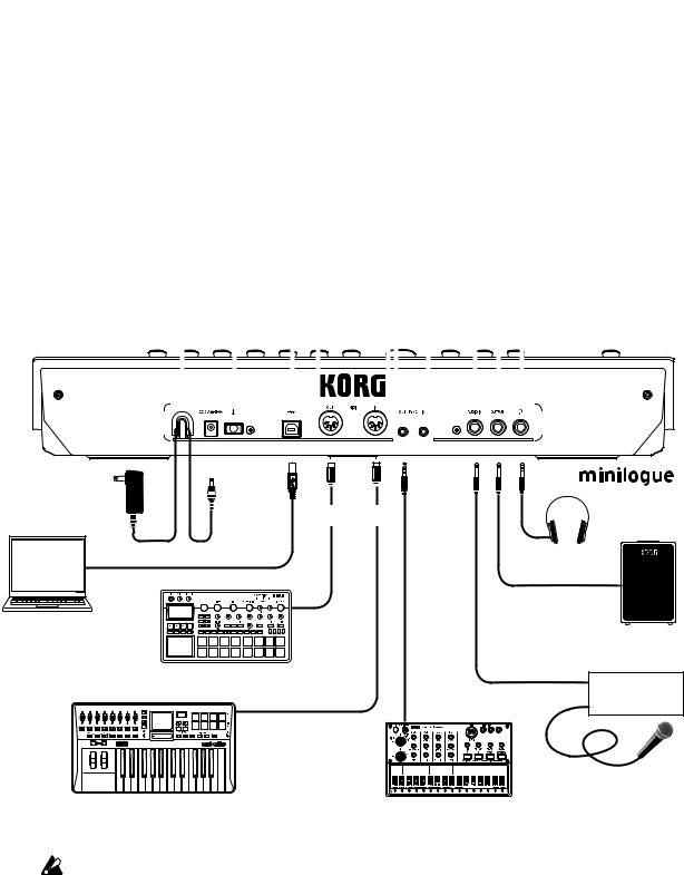
Rear Panel Connections
The illustration below shows a typical example of connections for the mini- logue. Connect your equipment according to the needs of your own system.
SYNC IN, OUT jacks |
|
|
|
|
|
|
|
|
|
|
AUDIO IN jack |
||||||||||||||
|
|
|
|
|
|
|
|
|
|
||||||||||||||||
The minilogue steps can be synchronized with other devices using |
|
|
|
|
|||||||||||||||||||||
|
|
|
|
||||||||||||||||||||||
these jacks. A pulse sent from the audio output of another device or |
|
|
|
|
This standard 1/4" TS jack accepts a |
||||||||||||||||||||
DAW can be used by connecting it to the SYNC IN jack. Use an 1/8" |
|
|
|
|
mono audio signal from another |
||||||||||||||||||||
cable (mini-phone plug) to sync with Korg volca products. |
|
|
|
|
synthesizer, instrument, or external |
||||||||||||||||||||
MIDI IN, OUT connectors |
|
|
|
|
|
|
|
|
|
|
|
|
sound source. |
||||||||||||
|
|
|
|
|
|
|
|
|
|
|
|
OUTPUT jack |
|||||||||||||
|
|
|
|
|
|
|
|
|
|
|
|
|
|||||||||||||
Connect these to an external MIDI device so that MIDI |
|
|
|
|
|
|
|
|
|
||||||||||||||||
|
|
|
|
|
|
|
|
|
|
||||||||||||||||
data can be transmi•ed or received. |
|
|
|
|
|
|
|
|
|
This standard 1/4" TS jack |
|||||||||||||||
USB B connector |
|
|
|
|
|
|
|
|
|
|
|
|
|
|
|
|
|
|
|
sends the sound of the |
|||||
|
|
|
|
|
|
|
|
|
|
|
|
|
|
|
|
|
|
minilogue to your powered |
|||||||
|
|
|
|
|
|
|
|
|
|
|
|||||||||||||||
This connector allows the minilogue to |
|
|
|
|
|
|
|
|
|
|
|
|
|
monitoring system, mixer, |
|||||||||||
exchange MIDI messages with your computer. |
|
|
|
|
|
|
|
|
|
|
|
|
|
recording setup, or external |
|||||||||||
Power switch |
|
|
|
|
|
|
|
|
|
|
|
|
|
|
|
|
|
|
|
|
amplifier. The level is |
||||
|
|
|
|
|
|
|
|
|
|
|
|
|
|
|
|
|
controlled by the MASTER |
||||||||
|
|
|
|
|
|
|
|
|
|
|
|
||||||||||||||
Hold this switch in to turn the |
|
|
|
|
|
|
|
|
|
|
|
|
|
|
knob. |
||||||||||
minilogue On or O . |
|
|
|
|
|
|
|
|
|
|
|
|
|
|
|
|
Headphones jack |
||||||||
Cable hook |
|
|
|
|
|
|
|
|
|
|
|
|
|
|
|
|
|
|
|
|
|
|
|
||
|
|
|
|
|
|
|
|
|
|
|
|
|
|
|
|
|
|
|
|
|
|
||||
|
|
|
|
|
|
|
|
|
|
|
|
|
|
|
|
|
|
|
|
|
|
|
Connect your headphones |
||
Loop the DC Plug end of the |
|
|
|
|
|
|
|
|
|
|
|
|
|
|
|
|
|
||||||||
|
|
|
|
|
|
|
|
|
|
|
|
|
|
|
|
|
here. This jack outputs the |
||||||||
AC Adapter cable around |
|
|
|
|
|
|
|
|
|
|
|
|
|
|
|
|
|
||||||||
|
|
|
|
|
|
|
|
|
|
|
|
|
|
|
|
|
same sound as the OUTPUT |
||||||||
this hook to prevent the cable |
|
|
|
|
|
|
|
|
|
|
|
|
|
|
|
|
|
||||||||
|
|
|
|
|
|
|
|
|
|
|
|
|
|
|
|
|
jack. |
||||||||
from being accidentally |
|
|
|
|
|
|
|
|
|
|
|
|
|
|
|
|
|
||||||||
|
|
|
|
|
|
|
|
|
|
||||||||||||||||
pulled out. |
|
|
|
|
|
|
|
|
|
|
|
|
|
|
|
|
|
|
|
||||||
|
|
|
|
|
|
|
|
|
|
|
|
|
|
|
|
|
|
|
|
|
|
|
|
|
|
|
|
|
|
|
|
|
|
|
|
|
|
|
|
|
|
|
|
|
|
|
|
|
|
|
|
|
|
|
|
|
|
|
|
|
|
|
|
|
|
|
|
|
|
|
|
|
|
|
|
|
|
|
|
|
|
|
|
|
|
|
|
|
|
|
|
|
|
|
|
|
|
|
|
|
|
|
|
|
|
|
|
|
|
|
|
|
|
|
|
|
|
|
|
|
|
|
|
|
|
|
|
|
|
|
|
|
|
|
|
|
|
|
|
|
|
|
|
|
|
|
|
|
|
|
|
|
|
|
|
DC 9V jack
AC adapter |
|
|
(included) |
MIDI cable |
|
USB cable |
|
Headphones |
USB port |
|
|
|
|
INPUT |
Computer |
MIDI IN |
Monitor speakers |
|
|
|
|
|
(with internal amp) |
Sound module, rhythm machine, etc. |
OUTPUT |
|
|
|
Mixer |
MIDI OUT |
|
SYNC IN |
|
|
|
|
|
Microphone |
MIDI keyboard, rhythm machine, etc. |
|
Groove machine |
You must make connections with the minilogue turned off. Failure to observe this precaution may cause malfunctions and/or damage to your speaker system.
5

Turning the minilogue On and Off
Before you turn the minilogue On:
Connect the AC adapter and other equipment.
1.Connect the included AC adapter to the DC 9V jack located on the rear panel.
Use only the included AC adapter. Using any other AC adapter may cause malfunctions.
2.Plug the AC adapter into an AC outlet.
3.Hook the AC adapter cable onto the cable hook to relieve stress on the connector and to prevent the cable from accidently being pulled out.
When disconnecting the power supply, do not use excessive force when removing the cable from the hook. Doing so may damage the plug.
4.Make sure that any external output devices such as powered monitor speakers are turned off before connecting them to the minilogue.
TIP If you want to connect a MIDI device or computer to the minilogue’s MIDI connectors or USB B connector in order to use the minilogue’s keyboard and controllers to control an external MIDI tone generator, or if you want to use another MIDI keyboard or a sequencer to play the minilogue’s sound generator, you will need to configure the set- tings. For details, (“Understanding MIDI”, p. 50).
Turning the minilogue On
1.Make sure that both the minilogue and any external output devices such as powered monitor speakers are turned off, and turn the volume of all devices all the way down.
2.Hold down the Power switch on the rear panel of the minilogue; once the
“minilogue” logo appears in the display, take your finger off the Power switch.
3.Turn on any external output devices such as powered monitor speakers.
4.Adjust the volume of your external output equipment, and adjust the minilogue’s volume using the MASTER knob.
6
Turning the minilogue Off
Any Program data in the minilogue that has not been saved will be lost when the power is turned off. Be sure to save any Program and other important data that you have edited (“Saving a Program”, p. 13).
1.Turn the MASTER knob of the minilogue to the left to turn the volume all the way down.
Also, turn the volume all the way down on any external output devices that might be connected, such as powered monitor speakers.
2.Hold down the Power switch on the rear panel of the minilogue; to turn off the power after the display goes blank, take your finger off the power switch.
Once you have turned the minilogue off, wait about 10 seconds before turning the minilogue on again.
Auto Power Off Feature
The minilogue features an Auto Power Off feature that can automatically turn the minilogue off after 4 hours have elapsed with no operation of the knobs, switches, buttons, or keyboard of the minilogue. By default, the factory setting for theAuto Power Off is enabled. The Auto Power Off can be disabled using the steps below.
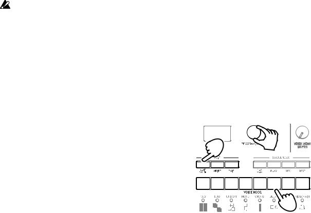
1. Press the EDIT MODE button. |
|
|
The minilogue will enter the Edit Mode, |
1 |
2, 4 |
and the display will look like the illustration |
||
shown below. |
|
|
|
|
6 |
|
|
3 |
2.Turn the PROGRAM/VALUE knob, and se- lect GLOBAL EDIT.
TIP GLOBAL EDIT can also be selected by pressing the EDIT MODE button.
3.Press button 6 twice.
“Auto Power Off” will be displayed.
4.Turn the PROGRAM/VALUE knob, and select “Off”.
5.Press the EXIT button.
The minilogue will enter the Play mode, and the display will indicate the current Program.
7
Playing Programs and Sequences
Selecting and Playing a Program
The minilogue comes equipped with 200 Programs. Of those, 100 are ready-to- play preset Programs and 100 locations are available to save your own sounds and custom edits.
Each Program includes settings for the sound, as well as sequence data and Voice mode settings.
1.Enter the Play mode.
When the minilogue is turned on, it will automatically enter the Play mode. In the Play mode, verify that all of the EDIT MODE and 1–8/9–16 buttons on the front panel are unlit.
TIP If the EDIT MODE button or the 1–8/9– 16 button is lit, press the EXIT button.
The PLAY or REC buttons will light to indicate when the sequence data saved in a Program is being played back or is recording. You can still select other Pro- grams in this state, but press the PLAY button if you wish to stop the Sequencer.


 2
2
1 Make sure they are unlit.
2.Turn the PROGRAM/VALUE knob to select a Program.
The display will indicate the Program name and number.
The minilogue comes with 100 preset Programs (001–100) as part of the fac- tory preload data. These preset Programs are instantly accessible and ready for you to enjoy. For details, refer to “Program List” (p. 54).
TIP Hold down the SHIFT button while turning the PROGRAM/VALUE knob to skip through the Program List in increments of 10.
TIP In addition to showing Program name and number, the display can also be used as anoscilloscope, to show the electrical signals created by the waveform of the sound. For details on the display, refer to “Os- cilloscope” (p. 45).
8

3.Adjusting the OCTAVE range, using the Slider, and changing the Voice
Mode.
As you play, you can use the five-way OCTAVE Switch to transpose the playing area of the keyboard by ± 2 octaves.
In addition, you can move the Slider from left to right to add real-time performance control.
TIP The parameter assigned to the slider will vary depend- ing on the Program. Rrefer to “Program List” (p. 54) to see which parameter is assigned to the slider in each Program.
TIP The Slider Assign function in PROGRAM EDIT mode is used to assign parameters to the slider (“Slider Assign”, p. 33).
In the Play mode, the LEDs below buttons |
|
1–8 show the Voice mode status of the cur- |
|
rent Program. You can use these buttons |
1 2 3 4 5 6 7 8 |
1–8 to switch between the different modes. |
|
For details, refer to “Voice modes” (p. 23).
Using Favorites
Recalling your Favorite Programs
The minilogue includes a Favorites function, which can be used to instantly recall any one of the up to eight Programs that you have previously registered as Favorites on the minilogue.
1.In the Play mode, press one of the but- tons from 1–8 while holding down the
SHIFT button.
The Favorite Program previously regis- tered to that button will be recalled, and the Program name and number will be indicated in the display.
1
1 2 3 4 5 6 7 8
1
9
Registering your Favorite Programs
You can register up to eight Programs that you particularly like as Favorite Programs.
1. In Play mode, turn the PROGRAM/
VALUE knob to select a Program you |
|
like. |
|
The display will indicate the Program |
|
name and number. |
1 |
|
|
2. Hold down one of the buttons from |
|
1–8 while keeping the SHIFT button |
|
pressed. |
1 |
2 |
3 |
4 |
5 |
6 |
7 |
8 |
The Program will be registered as a Fa- vorite program, and “Registered to Fa- vorite” will be indicated in the display.
TIP The favorite Programs that you
register will be saved in the Global settings.
2
2
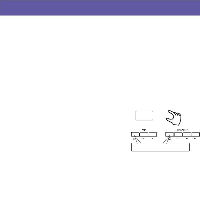
Playing the Sequencer
Each Program in the minilogue includes sequence data. In this section, we’ll play the sequence data saved as part of the preset Programs.
1. Turn the PROGRAM/VALUE knob to select
a Program. |
1 |
|
The display will indicate the Program name |
||
|
||
and number. |
|
|
2. Press the PLAY button in the SEQUENCER |
2, 3 |
|
section. |
The sequence data that is recorded in the cur- rent Program will begin playing.
The 1–8 buttons will light up in steps while the sequencer is playing.
TIP The Sequencer tempo is set for each Program in the SEQ EDIT mode and saved as part of the Program, but you can adjust the tempo from
56.0to 240.0 BPM (Beats Per Minute) by turning the TEMPO knob.
3.Press the PLAY button once more to end the Sequencer playback.
10
Programs
Program Architecture
Each minilogue Program includes settings for the Oscillators, Mixer, Filter, EGs and LFO, as well as a 16-Step Sequencer plus Effects.
Try editing each related parameter, and enjoy changing the sounds of the mini- logue.
|
|
|
|
|
|
|
|
|
|
|
|
|
|
|
|
|
|
|
|
|
|
|
|
|
|
|
|
|
|
|
|
|
|
Basic Parametres |
|
|
|
|
|
|
|
|
|
|
|
|
|
|
||
VCO 1 |
MIXER |
EG |
|
|
|
|
|
|
|
|
|
|
|
|
||
OCTAVE |
VCO1 |
ATTACK |
|
|
|
|
|
|
|
|
|
|
|
|
||
WAVE |
VCO2 |
DECAY |
|
|
|
|
|
|
|
|
|
|
|
|
||
PITCH |
NOISE |
SUSTAIN |
|
|
|
|
|
|
|
|
|
|
|
|
||
SHAPE |
FILTER |
RELEASE |
Sequence Data |
|
|
|
|
|||||||||
|
|
|
|
|
|
|
|
|||||||||
VCO 2 |
LFO |
|
|
|
|
|
|
|
|
|
|
|
|
|||
CUTOFF |
|
NOTE [STEP 1 16] |
|
|
|
|
||||||||||
OCTAVE |
RESONANCE |
WAVE |
|
|
|
|
|
|||||||||
WAVE |
EG INT |
EG MOD |
|
GATE TIME [STEP 1 16] |
|
|
||||||||||
PITCH |
FILTER TYPE |
RATE |
|
|
|
|
|
|
|
|
|
|
|
|
||
SHAPE |
KEYTRACK |
INT |
|
STEP 1 2 3 |
14 |
|
15 16 |
|||||||||
|
|
|
VELOCITY |
TARGET |
|
|
||||||||||
VCO 2 MODULATION |
AMP EG |
DELAY |
|
NOTE |
|
|
|
|
||||||||
CROSS MOD DEPTH |
|
|
||||||||||||||
|
GATE |
|
||||||||||||||
PITCH EG INT |
ATTACK |
HI PASS CUTOFF |
|
|
||||||||||||
|
|
|
|
|
||||||||||||
SYNC |
DECAY |
TIME |
|
|
|
|
|
|||||||||
RING |
SUSTAIN |
FEEDBACK |
Sequence Parameters |
|
|
|
|
|||||||||
|
|
|
RELEASE |
OUTPUTROUTING |
|
|
|
|
||||||||
|
|
|
|
|
|
|
|
|
|
|
|
|
|
|
||
|
|
|
|
|
|
BPM |
|
|
|
|
|
|
|
|
||
Detail Parametres |
|
|
|
Step Length |
|
|
|
|
||||||||
|
|
|
Step Resolution |
|
|
|
|
|||||||||
PROGRAM NAME |
LFO BPM Sync |
Portamento Time |
|
Swing |
|
|
|
|
|
|
|
|
||||
|
Default Gate Time |
|
|
|
|
|||||||||||
|
|
|
LFO Key Sync |
Portamento Mode |
|
|
|
|
|
|
|
|
|
|
|
|
Slider Assign |
LFO Voice Sync |
Portamento BPM |
|
Motion Type (1 4) |
|
|
|
|
||||||||
Bend Range + |
|
Amp Velocity |
|
Motion Enable (1 4) |
|
|
|
|
||||||||
Bend Range − |
|
Program Level |
|
Motion Smooth (1 4) |
|
|
|
|
||||||||
11

Creating Sounds
Editing a program means changing the Program’s parameters to alter its sound.
There are two way to create sounds on the minilogue.
•Select an existing Program that’s close to the sound you want, and edit that Program’s parameters to achieve your own custom sound.
•You can also initialize all the Program parameters or use the Panel Load func- tion to create your own sound from scratch.
Editing an Existing Program
1.In Program mode, select the Program that you want to use as a starting point.
2.Use the knobs and switches on the front panel.
Take a moment to consider the differences between the current Program and the sound you have in mind, and use the front panel controls to edit the necessary parameters.
TIP For details on how the pitch, sound, and volume change when using the knobs and switches, refer to “Basic Parameter Editing” (p. 14).
We recommend that you save the Program on the minilogue after editing the sound. Any edits that you make will be lost if you turn off the power or recall a different Program. For details, refer to “Saving a Program” (p. 13).
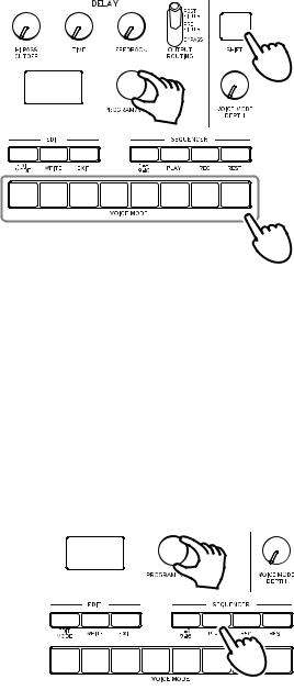
Creating a Program from Scratch
To create a sound from scratch, we recommend that you use thePanel Load function. This will load the current settings of each front panel control and provide a simple starting point for your iconic creations.
As you explore the front panel controls, you can see how each parameter will affect the sound, making it easier to understand how each section of the mini- logue functions and how the parameters interact.
PanelLoad function
Press the PLAY button while holding down the SHIFT button. The sound will change to reflect the panel settings, and “Load Panel” will be indicated in the display.
12

Saving a Program
We recommend that you save your Program on the minilogue after editing the sound.
Any edits that you make to the current program will be lost if you turn off the power or recall a different program before saving.
1.Edit the program in Play mode.
For details, refer to “Basic Parameter Editing” (p. 14).
2.Press the WRITE button; the minilogue will enter the Write standby mode, and the WRITE button will blink.
The message “Where to write?” will appear in the display.
3.Turn the PROGRAM/VALUE knob to select the Program number where your new sound will be saved.
Programs 1–100 are preset Programs, and Programs 101–200 are user Pro- grams.
TIP Press the EXIT button to cancel the operation.
4.Press the WRITE button once more.
The Program will be saved in internal memory, and the message “Com- plete” will appear in the display..
Never turn off the power while Programs are being saved. Doing so may destroy the internal data.
13
Basic Parameter Editing
In this section, we’ll explain the basic parameters that make up a program. The basic parameters are assigned to the knobs and switches on the front panel.
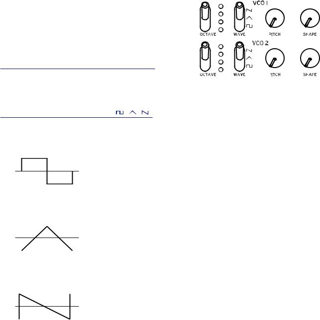
VCO 1, VCO 2
VCO: Voltage Controlled Oscillator
There are two oscillators in the minilogue. Os- cillator Parameters include the settings for the pitch of the sound (OCTAVE, PITCH) and the waveform (WAVE, SHAPE).
OCTAVE switch |
[16’, 8’, 4’, 2’] |
The pitch of oscillators 1 and 2 can be set in octave steps.
WAVE switch |
[ , , ] |
This sets the waveforms for oscillators 1 and 2.
Square wave: This waveform is used for electronic and wind instrument sounds.
Triangle wave: This waveform has a rounder feel than the sawtooth or square wave.
Sawtooth wave: This waveform is used to create sounds typical of analog syn- thesizers, such as synth basses and brass.
14

PITCH knob |
[−1200...+1200] |
The pitch, or tuning, of the Oscillators can be set using one-cent steps.
SHAPE knob |
[0...1023] |
This knob will determine the final shape, complexity, or duty-cycle (Square) of the selected waveform.
0  1023
1023
VCO 2 MODULATION
Oscillator 2 includes powerful oscillator sync, cross modulation, and ring modulation functions.
CROSS MOD DEPTH knob |
[0...1023] |
Cross Mod (Modulation) allows Oscillator 1 to mod- ulate the pitch of Oscillator 2.
Turning the knob to the right results in stronger modulation.
PITCH EG DEPTH knob |
[−4800...+4800] |
The Pitch EG (Envelope Generator) can be used to change the Pitch of Oscilla- tor 2 over time. In the center position, no effect is applied.
Positive values (turning the knob to the right of center) increase the Pitch EG effect; turning the knob to the left of center increases the Pitch EG effect using an inverted image of the EG shape (negative values).
To learn more about the EG settings, refer to “EG” (p. 20).
15

SYNC switch |
[OFF, ON] |
Oscillator sync is a popular effects for creating edgy synth leads.
ON (up position): With this type of modulation, the phase of oscillator 2 is forc- ibly synchronized to the phase of oscillator 1. This adds harmonic overtones to the frequency of oscillator 2, making a complex waveform.
VCO 1 Wave
Sync
VCO 2 Wave (original)
VCO 2 Wave (output)
RING switch |
[OFF, ON] |
Ring Modulation outputs the sum and difference of the frequencies created by the two oscillators.Adjust the pitch of Oscillator 2 to create non-tonal and me- tallic sounds.
ON (up position): Oscillator 1 is used to ring modulate oscillator 2.
VCO 1
VCO 2 
 RING MOD
MIXER
TheD mixer is used to set the relative levels of the three signal sources— Oscillator 1, Oscillator 2, and the Noise generator before they enter the filter.
|
VCO 1 knob |
[0... |
1023] |
|
VCO 2 knob |
[0... |
1023] |
These knobs control the output levels of oscillator 1 and 2.
NOISE knob |
[0...1023] |
Use this knob to set the output level of the noise generator. Noise (white noise) can be used on its own, or mixed with the Oscilla-
tors to create percussion instrument sounds, or sound effects such as surf.
16
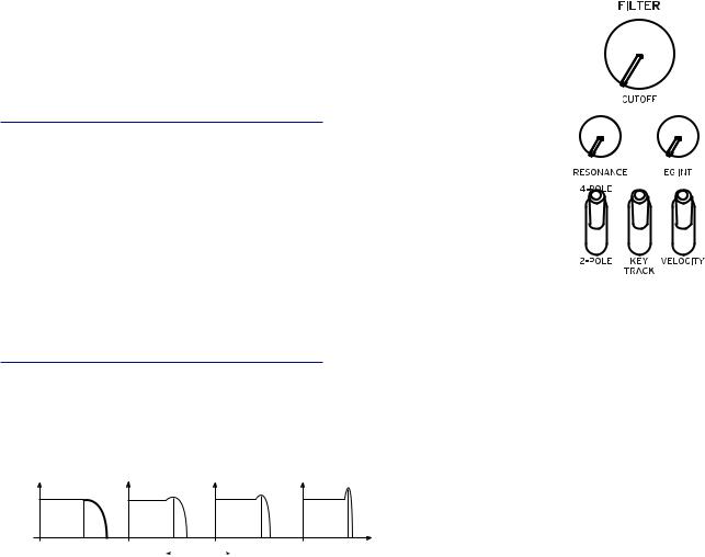
FILTER
VCF: Voltage Controlled Filter
The low-pass filter shapes the tone by selectively filtering cer- tain parts of the harmonic spectrum of the sound generated by the Oscillators and the Noise generator.
CUTOFF knob |
[0...1023] |
This knob is used to set the cutoff frequency. Harmonic con- tent above the cutoff frequency will be filtered out.
Turning the knob to the left will lower the cutoff frequency, and turning the knob to the right will raise the cutoff frequen- cy.
 If the CUTOFF value is set too low, the volume may be extremely low.
RESONANCE knob |
[0...1023] |
Also known as Peak or Q, the RESONANCE control adds additional emphasis to the overtones occurring at the CUTOFF frequency, giving a distinctive char- acter to the sound.
Turning the knob to the right will increase the resonance effect.
Low resonance value |
|
High resonance value |
|
TIP The overtones that are emphasized will change depending on the cut- off frequency. For this reason, it’s good to adjust the CUTOFF knob while adjusting the RESONANCE knob.
 When emphasizing the overtones in this way, the sound may distort depending on the cutoff frequency or the input audio.
17

EG INT knob |
[−100%...0...+100%] |
The Envelope Generator (EG) can be used to control the CUTOFF, or Filter fre- quency, over time using this EG INT (intensity) knob.
To learn more about the EG settings (“EG”, p. 20).
With this knob in the center position (0%), no EG is applied to the Filter.
Rotating the knob to the left of center increases the EG intensity, but with the polarity of the EG inverted.
Cuto
Note on Note o  Time
Time
Rotating the knob to the right of center increases the EG intensity effect.
Cuto
Note on Note o
|
|
Time |
|
|
|
FILTER TYPE switch |
[2-POLE, 4-POLE] |
|
The filter type (roll off) can be set to either 2-POLE (12 dB per octave) or 4-POLE (24 dB per octave).
2-POLE: Gently cuts off the upper harmonics, creating a more natural sound. 4-POLE: Cuts off the upper harmonics more sharply than the 2-POLE.
dB |
|
4-POLE |
2-POLE |
|
|||
24 |
|
|
|
|
|
|
|
|
|
|
|
|
|
||
12 |
|
|
|
|
|
|
|
0 |
|
|
|
|
|
|
|
|
|
|
|
|
|
||
-12 |
|
|
|
|
|
|
|
-24 |
|
|
|
|
|
Hz |
|
|
|
|
|
|
|
||
24 |
100 |
1k |
10k |
||||
|
|||||||
KEY TRACK switch [0%, 50%, 100%]
Key tracking allows the note played on the keyboard to influence the cutoff frequency of the filter. This is useful when you want higher notes to have more upper harmonics, or to appear brighter, than lower notes.
0% (lower position): No keyboard tracking will be applied.
50% (center position): The cutoff frequency will change at half the rate/slope as the pitch of the keyboard.
100% (upper position): The cutoff frequency will change at the same rate/slope as the pitch of the keyboard.
18
 Loading...