


E 2

INSTRUCTIONS PERTAINING TO A RISK OF FIRE, ELECTRIC SHOCK, OR INJURY TO PERSONS
IMPORTANT SAFETY INSTRUCTIONS
WARNING—When using electric products, basic precautions should always be followed, including the following:
1)Read all the instructions before using the product.
2)Do not use this product near water—for example, near a bathtub, washbowl, kitchen sink, in a wet basement, or near a swimming pool, or the like.
3)This product should be used only with a cart or stand that is recommended by the manufacturer.
4)This product, either alone or in combination with an amplifier and headphones or speakers, may be capable of producing sound levels that could cause permanent hearing loss. Do not operate for a long period of time at a high volume level or at a level that is uncomfortable. If you experience any hearing loss or ringing in the ears, you should consult an audiologist.
5)The product should be located so that its location or position does not interfere with its proper ventilation.
6)The product should be located away from heat sources such as radiators, heat registers, or other products that produce heat.
7)The product should be connected to a power supply only of the type described in the operating instructions or as marked on the product.
8)The power-supply cord of the product should be unplugged from the outlet when left unused for a long period of time.
9)Care should be taken so that objects do not fall and liquids are not spilled into the enclosure through openings.
10)The product should be serviced by qualified service personnel when:
a)The power-supply cord or the plug has been damaged; or
b)Objects have fallen, or liquid has been spilled onto the product; or
c)The product has been exposed to rain; or
d)The product does not appear to operate normally or exhibits a marked change in performance; or
e)The product has been dropped, or the enclosure damaged.
11)Do not attempt to service the product beyond that described in the user-maintenance instructions. All other servicing should be referred to qualified service personnel.
SAVE THESE INSTRUCTIONS
The lightning flash with arrowhead symbol within an equilateral triangle, is intended to alert the user to the presence of uninsulated “dangerous voltage” within the product’s enclosure that may be of sufficient magnitude to constitute a risk of electric shock to persons.
The exclamation point within an equilateral triangle is intended to alert the user to the presence of important operating and maintenance (servicing) instructions in the literature accompanying the product.
GROUNDING INSTRUCTIONS
This product must be grounded. If it should malfunction or breakdown, grounding provides a path of least resistance for electric current to reduce the risk of electric shock. This product is equipped with a cord having an equipment-grounding conductor and a grounding plug. The plug must be plugged into an appropriate outlet that is properly installed and grounded in accordance with all local codes and ordinances.
DANGER—Improper connection of the equipment-grounding conductor can result in a risk of electric shock. Check with a qualified electrician or serviceman if you are in doubt as to whether the product is properly grounded. Do not modify the plug provided with the product—if it will not fit the outlet, have a proper outlet installed by a qualified electrician.
THE FCC REGULATION WARNING (for U.S.A.)
This equipment has been tested and found to comply with the limits for a Class B digital device, pursuant to Part 15 of the FCC Rules. These limits are designed to provide reasonable protection against harmful interference in a residential installation. This equipment generates, uses, and can radiate radio frequency energy and, if not installed and used in accordance with the instructions, may cause harmful interference to radio communications. However, there is no guarantee that interference will not occur in a particular installation. If this equipment does cause harmful interference to radio or television reception, which can be determined by turning the equipment off and on, the user is encouraged to try to correct the interference by one or more of the following measures:
•Reorient or relocate the receiving antenna.
•Increase the separation between the equipment and receiver.
•Connect the equipment into an outlet on a circuit different from that to which the receiver is connected.
•Consult the dealer or an experienced radio/TV technician for help.
Unauthorized changes or modification to this system can void the user’s authority to operate this equipment.
CE mark for European Harmonized Standards
CE mark which is attached to our company’s products of AC mains operated apparatus until December 31, 1996 means it conforms to EMC Directive (89/336/EEC) and CE mark Directive (93/68/EEC).
And, CE mark which is attached after January 1, 1997 means it conforms to EMC Directive (89/336/EEC), CE mark Directive (93/68/EEC) and Low Voltage Directive (73/23/EEC).
Also, CE mark which is attached to our company’s products of Battery operated apparatus means it conforms to EMC Directive (89/336/EEC) and CE mark Directive (93/68/EEC).
IMPORTANT NOTICE FOR THE UNITED KINGDOM
WARNING—THIS APPARATUS MUST BE EARTHED
As the colours of the wires in the mains lead of this apparatus may not correspond with the coloured markings identifying the terminals in your plug,proceed as follows:
•the wire which is coloured green and yellow must be connected to the terminal in the plug which is marked with the letter E or by the earth symbol  , or coloured green or green and yellow.
•the wire which is coloured blue must be connected to the terminal which is marked with the letter N or coloured black.
•the wire which is coloured brown must be connected to the terminal which is marked with the letter L or coloured red.
i

 Handling of the internal hard disk
Do not apply physical shock to this device. In particular, you must never move this device or apply physical shock while the power is turned on. This can cause part or all of the data on disk to be lost, or may damage the hard disk or interior components.
When this device is moved to a location where the temperature is radically different, water droplets may condense on the disk drive. If the device is used in this condition, it may malfunction, so please allow several hours to pass before operating the device.
Do not repeatedly turn the power on/off. This may damage not only the D1600, but also any SCSI devices that are connected.
This device begins to access the hard disk immediately after the power is turned on.
Never turn off the power while the HDD access indicator is lit or blinking. Doing so can cause all or part of the data on disk to be lost, or may cause malfunctions such as hard disk damage.
If the hard disk has been damaged due to incorrect operation, power failure, or accidental interruption of the power supply, a fee may be charged for replacement even if this device is still within its warranty period.
Caution when transporting the D1600
When transporting the D1600, please pack it in the carton and shock-absorbing material in which it was originally packed.
If an internal IDE hard disk (e.g., HDD-20G) or internal CD-R/RW drive (e.g., CDRW-2) is installed, you must remove them from the D1600 and pack them in their own carton for transportation. Please take care that these units are not subjected to physical shock or vibration during transportation.
If the D1600 is transported with the hard disk and/ or CD-R/RW drive installed, data may be lost, or the D1600, hard disk, or CD-R/RW drive may malfunction.
Phantom Power
To prevent hazard or damage, ensure that only microphone cables and microphones designed to IEC-268-15A are connected.
COPYRIGHT WARNING
This professional device is intended only for use with works for which you yourself own the copyright, for which you have received permission from the copyright holder to publicly perform, record, broadcast, sell, and duplicate, or in connection with activities which constitute “fair use” under copyright law. If you are not the copyright holder, have not received permission from the copyright holder, or have not engaged in fair use of the works, you may be violating copyright law, and may be liable for damages and penalties. If you are unsure about your rights to a work, please consult a copyright attorney. KORG TAKES NO RESPONSIBILITY
FOR ANY INFRINGEMENT COMMITTED THROUGH USE OF KORG PRODUCTS.
For customers using the CDRW-2 drive
CAUTION FOR LASER
This product has been designed and manufactured according to FDA regulations “title 21. CFR. Chapter J. based on the radiation Control for Health and Safety Act of 1968”, and is classified as a class 1 laser product. There is no hazardous invisible laser radiation during operation because invisible laser radiation emitted inside of this product is completely confined in the protective housings.
The label required in this regulation is shown bellow.
CAUTION
Use of controls or adjustments or performance of procedures other than those specified herein may result in hazardous radiation exposure.
Optical pickup
Type: KRS-202A
Manufacturer: SONY CORPORATION
Laser output: Less than 0.1mW(Play) and 32mW(Record) on the objective lens
Wavelength: 777-787nm
* Appearance and specifications of this product are subject to change without notice.
•Company names, product names, and names of formats etc. are the trademarks or registered trademarks of their respective owners.
1

|
Table of Contents |
|
Introduction ...................................... |
5 |
|
Features................................................................................ |
5 |
|
Printing conventions in this manual................................ |
7 |
|
Panel overview of the D1600 ................................. |
8 |
|
Top panel ............................................................................. |
8 |
|
Front panel......................................................................... |
11 |
|
Rear panel .......................................................................... |
11 |
|
Objects in the LCD screen and their functions ........ |
13 |
|
Objects in the LCD screen ............................................... |
13 |
|
Adjusting the LCD screen contrast ................................ |
14 |
|
Basic operation.................................................................. |
14 |
|
1. |
Selecting a mode..................................................... |
14 |
2. |
Selecting a tab page................................................ |
14 |
3. |
Selecting and setting a parameter ........................ |
14 |
Basic operation............................... |
15 |
|
Step 0. Starting.................................................... |
15 |
|
1. |
Preparations ............................................................ |
15 |
2. |
Using the D1600...................................................... |
15 |
Step 1. Making connections, and turning the |
|
|
power on/off....................................................... |
17 |
|
1. |
Connections............................................................. |
17 |
2. |
Turning the power on/off..................................... |
18 |
Listening to the demo song............................................. |
19 |
|
Step 2. Creating/selecting a song......................... |
21 |
|
1. |
Creating a new song .............................................. |
21 |
2. |
Naming a song........................................................ |
21 |
3. |
Selecting another song........................................... |
22 |
Step 3. Assign audio inputs to the mixer ............... |
23 |
|
1. |
Analog inputs.......................................................... |
23 |
2. |
Digital input ............................................................ |
25 |
3. |
Using the tuner ....................................................... |
25 |
Step 4. Recording ................................................ |
27 |
|
1. |
Adjust the recording level, and record................ |
27 |
2. |
Recording on virtual tracks................................... |
27 |
3. |
Playback while recording addition tracks: |
|
|
Overdubbing........................................................... |
28 |
4. |
Re-record part of a performance: Punch-in/out 28 |
|
5. |
Combining multiple tracks into two: Bounce .... |
29 |
Other recording methods ................................................ |
31 |
|
Step 5. Playback.................................................. |
33 |
|
1. |
Playback................................................................... |
33 |
2. |
Program play........................................................... |
33 |
Other playback options ................................................... |
33 |
|
Step 6. Changing the time location ....................... |
35 |
|
1. |
Switching the counter display .............................. |
35 |
2. |
Moving the current time location ........................ |
35 |
3. |
Using scrub playback etc. to find a precise |
|
|
time location............................................................ |
36 |
Step 7. Using the mixer........................................ |
37 |
|
1. |
Adjusting the volume ............................................ |
37 |
2. |
Adjusting the stereo position................................ |
37 |
3. |
Using EQ to adjust the tone .................................. |
37 |
4. |
Pairing ...................................................................... |
38 |
5. |
Monitor settings...................................................... |
38 |
6. |
Solo settings............................................................. |
39 |
7. |
Registering and playing scenes............................ |
39 |
Step 8. Using effects ............................................. |
43 |
|
Overview of the effects.................................................... |
43 |
|
1. |
Insert effects ............................................................ |
43 |
2. |
Master effects.......................................................... |
45 |
3. |
Final effect ............................................................... |
46 |
4. |
Editing an effect ..................................................... |
46 |
Controlling an effect from an external device ............. |
47 |
|
Using an external effect................................................... |
48 |
|
Step 9. Mixdown.................................................. |
49 |
|
1. |
Creating an audio CD............................................ |
49 |
2. |
Recording to a master tape ................................... |
50 |
3. |
Using the sub inputs.............................................. |
50 |
Step 10. Track editing........................................... |
51 |
|
1. |
Track editing functions ......................................... |
51 |
2. |
Track editing examples ......................................... |
52 |
Step 11. Song editing ........................................... |
59 |
|
1. |
Song editing procedure......................................... |
59 |
2. |
Examples of song editing...................................... |
59 |
Step 12. Rhythm/tempo settings ........................... |
61 |
|
1. |
Specifying and playing a rhythm ........................ |
61 |
2. |
Recording your performance while you listen |
|
|
to the rhythm .......................................................... |
61 |
3. |
Recording the rhythm ........................................... |
61 |
4. |
Setting the tempo ................................................... |
62 |
Step 13. Saving your data .................................... |
65 |
|
1. |
Copy Song, Copy All Songs ................................. |
65 |
2. |
Backup/Restore ..................................................... |
65 |
3. |
Connecting external drives................................... |
67 |
4. |
Importing/exporting WAV files.......................... |
68 |
Drive and data compatibility within the Digital |
|
|
Recording Studio series................................................... |
70 |
|
Regarding disk capacity.................................................. |
71 |
|
Note when using DOS format disks.............................. |
72 |
|
Step 14. MIDI ....................................................... |
73 |
|
1. |
MIDI connections................................................... |
73 |
2. |
MIDI messages used by the D1600...................... |
73 |
3. |
Using MIDI ............................................................. |
73 |
Reference....................................... |
75 |
|
1. COUNTER ........................................................ |
75 |
|
Counter: Counter display ............................................... |
75 |
|
2. SYSTEM............................................................ |
75 |
|
P1 Control: Foot switch/control change device |
|
|
(pedal/MIDI) settings ................................................ |
75 |
|
P2 MIDI: MIDI settings.................................................... |
76 |
|
P3 Sync: Synchronization settings ................................. |
76 |
|
P4 MMC: MMC settings .................................................. |
77 |
|
P5 B–U/Rst: Backing-up and restoring data to |
|
|
removable disk ............................................................ |
77 |
|
P6 DiskUtil: Initialize/format/check a drive............... |
79 |
|
3. RECORD........................................................... |
80 |
|
P1 RecMode: Selecting the recording mode ................. |
80 |
|
P2 Bounce: Settings for bounce recording .................... |
81 |
|
4. TRACK ............................................................. |
81 |
|
P1 Vtr1–8: Select virtual tracks 1–8 ................................ |
81 |
|
P2 Vtr9–16: Select virtual tracks 9–16 ............................ |
81 |
|
P3 EditTrk: Track editing ................................................ |
81 |
|
P4 Import: Import a WAV file ........................................ |
86 |
|
P5 Export: Export a WAV file ......................................... |
87 |
|
2

5. SONG ............................................................. |
88 |
P1 SelSong: Selecting a song ........................................... |
88 |
P2 EditSong: Song editing ............................................... |
89 |
P3 PrgPlay: Program playback of songs........................ |
90 |
P4 CDR/RW: Creating and playing a CD-R/RW ....... |
91 |
6. STORE ............................................................. |
92 |
7. MARK ............................................................. |
92 |
P1 Mark: Editing marks ................................................... |
92 |
8. SCENE............................................................. |
93 |
P1 ReadDel: Scene playback on/off and editing ......... |
93 |
P2 MixView: Pan/fader scene display .......................... |
94 |
9. TEMPO/RHYTHM ............................................. |
95 |
P1 SetUp: Tempo and rhythm settings.......................... |
95 |
P2 TmpMap: Editing the tempo map ............................ |
95 |
P3 TmpTrk: Create a tempo track .................................. |
96 |
10. IN/LOC1, OUT/LOC2, TO/LOC3, END/LOC4.. 97 |
|
11. AUTO PUNCH................................................ |
98 |
P1 AtPunch: Settings for auto punch-in/out |
|
recording....................................................................... |
98 |
12. LOOP ............................................................ |
99 |
P1 Loop: Loop playback/recording settings ................ |
99 |
13. UNDO........................................................... |
99 |
14. TRIGGER...................................................... |
100 |
P1 Trigger: Settings to start trigger recording ............ |
100 |
15. SCRUB......................................................... |
101 |
16. ENTER ......................................................... |
101 |
17. INPUT ......................................................... |
102 |
P1 Ch1–8: Select the inputs for mixer channels 1–8... |
102 |
P2 Ch9–16: Select the inputs for mixer channels |
|
9–16.............................................................................. |
103 |
P3 InEq1–4: EQ settings for inputs 1–4........................ |
103 |
P4 InEq5–8: EQ settings for inputs 5–8........................ |
103 |
P5 Tuner: Tuner .............................................................. |
103 |
18. EQ/PHASE .................................................. |
104 |
P1 Eq1–4: EQ settings for mixer channels 1–4 ............ |
104 |
P2 Eq5–8: EQ settings for mixer channels 5–8 ............ |
104 |
P3 Eq9–12: EQ settings for mixer channels 9–12 ........ |
104 |
P4 Eq13–16: EQ settings for mixer channels 13–16 .... |
104 |
P5 Phase: Phase settings for mixer channels............... |
104 |
19. INSERT EFFECT ............................................. |
105 |
P1 InsAss: Insert effect insertion location/type ......... |
105 |
P2 InsEff1: Selection and settings for Insert |
|
Effect 1......................................................................... |
106 |
P3 InsEff2: Selection and settings for Insert |
|
Effect 2......................................................................... |
107 |
P4 InsEff3: Selection and settings for Insert |
|
Effect 3......................................................................... |
107 |
P5 InsEff4: Selection and settings for Insert |
|
Effect 4......................................................................... |
107 |
P6 Ins5–8: Selection and settings for Insert Effects |
|
5–8................................................................................ |
107 |
20. MASTER EFFECT/AUX/FINAL EFFECT............. |
107 |
P1 MstEff1: Selection and settings for master effect 1107 |
|
P2 MstEff2: Selection and settings for master effect 2108 |
|
P3 EffSnd1: Send settings for effect 1........................... |
108 |
P4 EffSnd2: Send settings for effect 2........................... |
108 |
P5 AuxSend: External send settings............................. |
108 |
P6 FinalEff: Selection and settings for the final |
|
effect ............................................................................ |
108 |
21. SOLO/MONITOR ......................................... |
109 |
|
P1 Solo: Solo select .......................................................... |
109 |
|
P2 Monitor: Monitor settings......................................... |
110 |
|
22. METER/TRACK VIEW .................................... |
111 |
|
23. TRACK STATUS............................................. |
111 |
|
24. PAN ............................................................ |
111 |
|
25. FADER ......................................................... |
112 |
|
26. TRANSPORT KEYS ........................................ |
112 |
|
Effect Parameter List ..................... |
113 |
|
Insert (2in2outx2)/Master/Final Effect................. |
113 |
|
Reverb RV1 – RV7 |
|
|
Category: Reverb-type effects ....................................... |
113 |
|
1: |
RV1: Reverb Hall ................................................................... |
113 |
2: |
RV2: Smooth Hall .................................................................. |
113 |
3: |
RV3: Reverb Wet Plate.......................................................... |
113 |
4: |
RV4: Reverb Dry Plate .......................................................... |
113 |
5: |
RV5: Reverb Room ................................................................ |
113 |
6: |
RV6: Bright Room.................................................................. |
113 |
7: |
RV7: Early Reflection ............................................................ |
113 |
Delay DL1 – DL6 Category: Delay-type effects.......... |
113 |
|
8: DL1: L/C/R Delay ................................................................ |
113 |
|
9: |
DL2: St/Cross Delay (Stereo/Cross Delay)....................... |
114 |
10: DL3: St.Multitap Delay (Stereo Multitap Delay) .............. |
114 |
|
11: DL4: St.Modulation Delay.................................................... |
114 |
|
12: DL5: St.Dynamic Delay (Stereo Dynamic Delay) ............. |
114 |
|
13: DL6: St.Auto Panning Delay................................................ |
115 |
|
Modulation MO1– MO7 |
|
|
Category: Modulation-type effects............................... |
115 |
|
14: MO1: St.Chorus (Stereo Chorus)......................................... |
115 |
|
15: MO2: St.Flanger (Stereo Flanger)........................................ |
115 |
|
16: MO3: St.Phaser (Stereo Phaser)........................................... |
115 |
|
17: MO4: St.Vibrato (Stereo Vibrato) ........................................ |
115 |
|
18: MO5: St.Tremolo (Stereo Tremolo)..................................... |
116 |
|
19: MO6: St.Auto Pan (Stereo Auto Pan) ................................. |
116 |
|
20: MO7: Ensemble...................................................................... |
116 |
|
Dynamics DY1 – DY7 |
|
|
Category: Dynamics-type effects .................................. |
116 |
|
21: DY1: St.Compressor (Stereo Compressor)......................... |
116 |
|
22: DY2: St.Limiter (Stereo Limiter).......................................... |
116 |
|
23: DY3: Multiband Limiter ....................................................... |
117 |
|
24: DY4: St.Gate (Stereo Gate) ................................................... |
117 |
|
25: DY5: St.Exciter/Enhancer .................................................... |
117 |
|
26: DY6: St.Decimator (Stereo Decimator)............................... |
117 |
|
27: DY7: St.Parametric 4band EQ.............................................. |
118 |
|
Special Effect SE1 – SE4 Category: Special Effect....... |
118 |
|
28: SE1: St.Ring Modulator ........................................................ |
118 |
|
29: SE2: Doppler........................................................................... |
118 |
|
30: SE3: St.Analog Record .......................................................... |
118 |
|
31: SE4: Talking Modulator........................................................ |
118 |
|
Insert (2in2outx2), Final...................................... |
119 |
|
Large size LS1 – LS7 Category: Large size effects ...... |
119 |
|
32: LS1: St.Graphic 7band EQ .................................................... |
119 |
|
33: LS2: St.Multiband Limiter .................................................... |
119 |
|
34: LS3: Vocoder .......................................................................... |
119 |
|
35: LS4: St.Pitch Shifter ............................................................... |
119 |
|
36: LS5: Early Reflections L ........................................................ |
119 |
|
37: LS6: Rotary Speaker .............................................................. |
120 |
|
38: LS7: Center Canceller............................................................ |
120 |
|
Insert (1in2outx2)............................................... |
120 |
|
GT1 – GT6 Category: Guitar multi ............................... |
120 |
|
39: GT1: Guitar Multi1 ................................................................ |
120 |
|
40: GT2: Guitar Multi2 ................................................................ |
120 |
|
41: GT3: Guitar Multi3 ................................................................ |
120 |
|
42: GT4: Guitar Multi4 ................................................................ |
120 |
|
43: GT5: Guitar Multi5 ................................................................ |
120 |
|
44: GT6: Guitar Multi6 ................................................................ |
120 |
|
3

AS1 – AS3 Category: Guitar amp simulator............... |
120 |
45: AS1: Amp Simulator1........................................................... |
120 |
46: AS2: Amp Simulator2........................................................... |
120 |
47: AS3: Amp Simulator3........................................................... |
120 |
PA1 Category: Pre-amp simulator............................... |
121 |
48: PA1: Pre Amp Simulator...................................................... |
121 |
EB1 – EB3 Category: Bass multi ................................... |
121 |
49: EB1: Bass Multi1 .................................................................... |
121 |
50: EB2: Bass Multi2 .................................................................... |
121 |
51: EB3: Bass Multi3 .................................................................... |
121 |
MS1 Category: Mic multi .............................................. |
121 |
52: MS1: Mic Multi ...................................................................... |
121 |
VO1 – VO2 Category: Vocal multi ............................... |
121 |
53: VO1: Vocal Multi1................................................................. |
121 |
54: VO2: Vocal Multi2................................................................. |
121 |
Effects within multi-effect programs GT1–VO2, and |
|
their parameters.............................................................. |
121 |
Dist (Distortion)........................................................................... |
121 |
NR (Noise Reduction)................................................................. |
121 |
Comp (Compressor/Limiter).................................................... |
121 |
P4EQ (Parametric 4band EQ) .................................................... |
121 |
Exctr (Exciter)............................................................................... |
121 |
Wah ............................................................................................... |
121 |
Filter .............................................................................................. |
121 |
AmpSim (AmpSimulator).......................................................... |
122 |
CabRes (CabinetResonator) ....................................................... |
122 |
Tone............................................................................................... |
122 |
Gate ............................................................................................... |
122 |
DeEss (Deesser) ........................................................................... |
122 |
Cho/Fl (Chorus/Flanger) .......................................................... |
122 |
Treml (Tremolo) .......................................................................... |
122 |
Phaser............................................................................................ |
122 |
Delay ............................................................................................. |
122 |
S.Dly (Stereo Delay) .................................................................... |
122 |
Pitch (Pitch shifter)...................................................................... |
122 |
MicSim (Mic Simulator) ............................................................. |
123 |
Insert (1in1outx4) .............................................. |
123 |
55: MM1: P4EQ – Exciter............................................................ |
123 |
56: MM2: P4EQ – Wah................................................................ |
123 |
57: MM3: P4EQ – Cho/Flng ...................................................... |
123 |
58: MM4: P4EQ – Phaser ............................................................ |
123 |
59: MM5: P4EQ – Mt.Delay........................................................ |
123 |
60: MM6: Comp – Wah............................................................... |
123 |
61: MM7: Comp – AmpSim ....................................................... |
123 |
62: MM8: Comp – OD/HiG....................................................... |
123 |
63: MM9: Comp – P4EQ ............................................................. |
123 |
64: MM10: Comp – Cho/Flng ................................................... |
123 |
65: MM11: Comp – Phaser ......................................................... |
123 |
66: MM12: Comp – Mt.Delay..................................................... |
123 |
67: MM13: Exciter – Comp......................................................... |
123 |
68: MM14: Exciter – Limiter....................................................... |
124 |
69: MM15: Exciter – Cho/Flng .................................................. |
124 |
70: MM16: Exciter – Phaser........................................................ |
124 |
71: MM17: Exciter – Mt.Delay ................................................... |
124 |
72: MM18: Limiter – P4EQ ......................................................... |
124 |
73: MM19: Limiter – Cho/Flng ................................................. |
124 |
74: MM20: Limiter – Phaser ....................................................... |
124 |
75: MM21: Limiter – Mt.Delay................................................... |
124 |
76: MM22: OD/HiG – Cho/Flng .............................................. |
124 |
77: MM23: OD/HiG – Phaser.................................................... |
124 |
78: MM24: OD/HiG – Mt.Delay ............................................... |
124 |
79: MM25: OD/HiG – AmpSim ................................................ |
124 |
80: MM26: Wah – AmpSim........................................................ |
124 |
81: MM27: Decimator – AmpSim.............................................. |
124 |
82: MM28: Decimator – Comp................................................... |
124 |
83: MM29: Cho/Flng – Mt.Delay.............................................. |
124 |
84: MM30: Phaser – Cho/Flng .................................................. |
124 |
85: MM31: AmpSim – Tremolo ................................................. |
124 |
86: MM32: Reverb – Gate ........................................................... |
124 |
87: MM33: MicSim – Limiter ..................................................... |
124 |
Effects within multi-effect programs MM1–MM33, |
|
and their parameters ...................................................... |
124 |
P4EQ (Parametric 4band EQ) .................................................... |
124 |
Excit1 (Exciter1) ........................................................................... |
124 |
Excit2 (Exciter2) ........................................................................... |
124 |
Wah (Wah/Auto Wah)............................................................... |
124 |
Comp1 (Compressor1)................................................................ |
124 |
Comp2 (Compressor2)................................................................ |
125 |
Lmtr (Limiter) .............................................................................. |
125 |
AmpSim (Amp Simulator)......................................................... |
125 |
MicSim (Mic Simulator).............................................................. |
125 |
Decima (Decimator) .................................................................... |
125 |
ODHiG (OverDrive/HighGain)................................................ |
125 |
ChFl1 (Chorus/Flanger)............................................................. |
125 |
ChFl2 (Chorus/Flanger2)........................................................... |
125 |
Phaser ............................................................................................ |
125 |
Trml (Tremolo)............................................................................. |
125 |
Mt.Dly (Multitap Delay)............................................................. |
125 |
Reverb (Mono Reverb)................................................................ |
125 |
Gate................................................................................................ |
125 |
Insert (1in1outx8) ............................................... |
126 |
88: MN1: OverDrive/HighGain................................................ |
126 |
89: MN2: Compressor2 ............................................................... |
126 |
90: MN3: Limiter.......................................................................... |
126 |
91: MN4: Gate............................................................................... |
126 |
92: MN5: Exciter2......................................................................... |
126 |
93: MN6: Parametric 4band EQ................................................. |
126 |
94: MN7: Amp Simulator ........................................................... |
126 |
95: MN8: Multitap Delay............................................................ |
126 |
96: MN9: Chorus/Flanger2........................................................ |
126 |
97: MN10: Phaser......................................................................... |
126 |
98: MN11: Expander.................................................................... |
126 |
Effect Control...................................................... |
126 |
Cntrl (Control) ............................................................................. |
126 |
Appendices .................................. |
127 |
Troubleshooting.................................................. |
127 |
Messages........................................................... |
131 |
Confirmation messages............................................ |
131 |
Error messages .......................................................... |
131 |
Installing a hard disk or CD-R/RW drive.............. |
134 |
1. About the internal hard disk .............................. |
134 |
2. About the internal CD-R/RW drive ................. |
136 |
3. Using the internal CD-R/RW drive .................. |
138 |
Updating the system software............................. |
139 |
D1600 specifications .......................................... |
140 |
MIDI implementation chart.................................. |
142 |
Block diagram.................................................... |
143 |
Effect Program List.............................................. |
144 |
Rhythm Pattern List (215patterns) ........................ |
146 |
Demo Song List................................................... |
147 |
Index ................................................................. |
147 |
4
Introduction
Thank you for purchasing the Korg D1600 Digital Recording Studio.
To ensure trouble-free enjoyment, please read this manual carefully and use the instrument as directed.
Features
•The D1600 is a 16 track digital multi-track recorder (MTR) with full-digital processing (24 bit internal processing, 16/24 bit uncompressed recording and playback, 44.1 kHz sampling frequency).
From recording to effect processing to mixing down to CD-R/RW (a CD-R/RW drive is required), all processing is performed completely in the digital domain.
•It contains a 16 track recorder, a 24-channel 8-bus mixer, and effects.
When using 16 bit recording/playback: 8 tracks can be recorded simultaneously, and 16 tracks can be played back simultaneously.
When using 24 bit recording/playback: 4 tracks can be recorded simultaneously, and 8 tracks can be played back simultaneously.
•User-installable internal hard disk.
You can install either a separately sold Korg HDD20G hard disk drive or any Korg-recommended 3.5 inch IDE hard disk drive. An internal hard disk allows approximately 3.1 hours of recording for each gigabyte (16 bit, 1 track). If the HDD-20G hard disk drive (sold separately) is installed, approximately 62
hours of recording is possible.
A maximum of 100 songs × 16 tracks × 8 virtual tracks can be recorded, for a total maximum of 12,800 tracks of data.
•User-installable internal CD-R/RW drive. You can install either a separately sold Korg CDRW-2 CD-R/ RW drive or any Korg-recommended 5 inch ATAPI internal CD-R/RW drive. If a CD-R/RW drive is installed, you will be able to create original CD’s and back up song data, and record audio data from a CD without connecting any other equipment to the D1600.
•All analog inputs in the mixer section use high-per- formance balanced preamps to take full advantage of the audio quality of full-digital processing.
XLR inputs with +48V phantom power and a dedicated guitar input are provided. A wide variety of audio sources can be connected directly, from mic level to +16 dBu (higher than professional level). All phone jack inputs use TRS balanced jacks to support balanced input. Of course, unbalanced input is also supported.
The S/PDIF digital input provides a sampling rate converter that automatically converts 48 kHz or 32 kHz sources to 44.1 kHz.
•Each analog input/mixer channel provides high EQ, mid EQ, and low EQ. The mid EQ has an adjustable cutoff frequency.
EQ is provided separately for input and mixer channels, preventing the problem that can occur on MTR units with an analog mixer when recording EQ settings are applied again to the playback.
•The built-in effects use Korg’s “ ” modeling technology, putting detailed and powerful effect models at your fingertips.
•Up to eight insert effects are available for insertion into analog input/mixer channels; signals from each channel can be sent to the two master effects, and an independent final effect can be applied to the master output.
For the insert effects, master effects, and final effects you can choose from 98 different types of high quality effect, and use up to five effects simultaneously.
The D1600 provides 128 insert effect presets, 32 master effect presets, and 32 final effect presets created by professional musicians and studio engineers, for a total of 192 preset effect programs. Based on these preset programs, you can edit your own settings and save them in one of the 192 user effect locations. An expression pedal (separately sold option) can be connected to control an insert effect in realtime.
•The built-in tuner lets you tune a connected guitar or check the tuning of a playback track.
•The fader, EQ, pan, and effect settings of the mixer section can be saved in a scene, and 100 scenes can be registered for each song. You can cause scenes to change automatically as playback progresses, or recall them as general-purpose settings when needed.
•Operations such as recorded, copy, and delete are performed as non-destructive editing. You can use the Undo function to reverse any record or edit operations previously executed. Then use the Redo function to cancel the “undo.” Undo allows up to 99 prior recording or editing operations to be undone.
•Songs or phrases that you create by recording or editing will be saved to disk automatically by the Auto Save function when you switch songs, eliminating the need to save the data manually.
•Each track provides eight virtual tracks.
For example, you might record different takes of a solo part on different virtual tracks, and then choose the best performance later. When using bounce (ping-pong) recording, currently-unused virtual tracks can be specified as the bounce destination, allowing you to combine multiple tracks of data into two tracks without erasing any of the 16 tracks. By repeating this “16 to 2 track bounce” operation, you can theoretically create a song of 16 x 8 tracks = 128 tracks without erasing any of the original track data.
•In addition to a conventional metronome sound, 215 rhythm patterns in a variety of musical styles are built-in, allowing you to hear a more musically interesting rhythmic guide as you record. You can select a favorite rhythm and start recording right away,
Introduction |
|
|
|
Panel overview of |
the D1600 |
|
|
|
|
in the LCD screen and |
their functions |
Objects |
|
|
|
5

without having to connect and set up a drum machine. These rhythm patterns can also be recorded on a track.
•Auto and manual punch-in/out recording make it easy to re-record the desired portion of a performance.
•The Trigger Recording function allows recording to start automatically in response to an audio input, so that it’s easy to begin recording even when both hands are occupied playing an instrument. You can also use a foot switch to start or stop recording.
•The Scrub function lets you listen to the recorded sound of a track just as if you were manually moving the reels of an open-reel tape recorder – a great convenience when you need to find the exact beginning of a phrase.
•The Locate Point Memory function (four points for each song) and Mark Memory function (100 points for each song) allow you to register locations within a song, making it easy to mark and jump instantly to transitional points within the song. Names can also be assigned to marks.
•The Program Play function lets you play back multiple songs in the order you specify. These songs can then be recorded to MD or DAT to create your own album.
•When recording and editing songs or phrases from a record or CD, you can use tap input to input a tempo that follows the song. Alternatively, you can create tempo maps, or record MIDI clock messages from an external device.
•The D1600 can synchronize with MIDI Clock, MTC, or MMC-compatible sequencers or rhythm machines.
•Standard connectors such as SCSI and S/P DIF (digital interface) are provided, allowing connection to numerous external devices. The SCSI connector allows external hard disks, CD-R/RW, or removable disks to be used to record/play or backup data. The S/P DIF connectors allow you to record digital audio from an external digital device such as DAT or MD, and to directly output the mixdown of a song you created for recording on an external DAT or MD.
AUX OUT jacks allow external effect devices to be connected.
•WAV files can be imported/exported, making it easy for audio data to be exchanged with your computer.
•Mixer parameters can be controlled via MIDI. An external MIDI sequencer can be used to implement mixer automation.
•Data backed up by the D8, D12 and D16 digital recording studio units can be restored into the D1600, allowing easy transfer of data. Playable D12, D16 drives can also be played back by the D1600.
What is  ?
?
 (Resonant structure and Electronic circuit Modeling System) is KORG’s proprietary sound modeling technology which precisely reproduces the complex character and nature of both acoustic and electric instruments as well as electronic circuits in real world environments.
 emulates a wide variety of sound generation characteristics including instrument bodies, speakers & cabinets, acoustic fields, microphones, vacuum tubes, transistors, etc.
6
Printing conventions in this manual
Switches and knobs [ ]
Keys, dials, and knobs on the panel of the D1600 are printed within [square brackets].
Parameters that appear in the LCD screen “ ”
Parameters that appear in the LCD screen are printed inside “double quotation marks.” The terms ‘button’ and ‘cell’ refer to objects in the LCD screen.
 The LCD screen of the D1600 is a touch panel. To select a parameter, simply touch that parameter directly. Alternatively, you can use the [CURSOR] key to move the cursor to the desired parameter. Most of the procedure examples given in this manual will use the method of directly pressing the parameter in the LCD screen to select it (→ p.14).
Bold-face type
Panel settings such as for faders or the [TRACK STATUS] keys are printed in bold type, and parameter values are printed in “bold type.”
Bold type also indicates content within the text that we wish to emphasize.
Steps 1 2 3 …
Steps in a procedure are indicated as 1 2 3 …
p.■■
This indicates a page or parameter number for reference.
Symbols  ,
, 
These symbols respectively indicate points of caution and notes of advice.
[...] “xx” tab page
This indicates a page displayed in the LCD screen. To access this page, press the [...] key on the panel.
If there is more than one tab, the tab pages will be selected successively each time you press the [...] key.
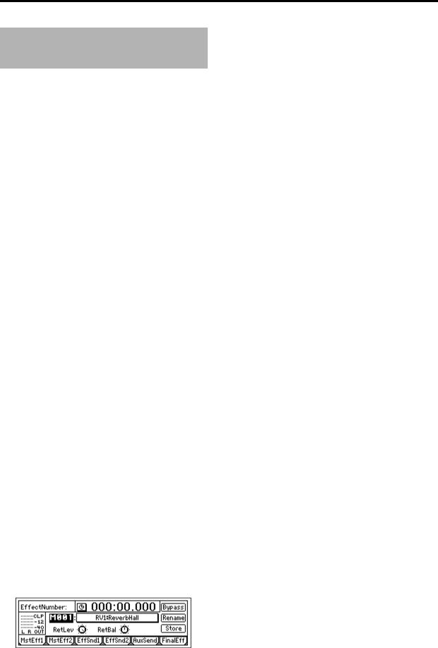
 Example: The currently selected tab page. The illustration below shows the [MASTER
EFFECT/AUX] “MstEff1” tab page. To select this tab page, press the top panel [MASTER EFFECT/ AUX] key.
The various objects in the tab page are parameters etc. There are also underlines, popup buttons, and icons.
In the figure shown, “EffectNumber,” “RetLev” and “Rename” buttons etc. are parameters. Currently, “EffectNumber” is highlighted, and can be edited. The current value is “M001,” and this will change if you rotate the [VALUE] dial. (→ p.14)
When you press the [MASTER EFFECT/AUX] key once again, the [MASTER EFFECT/AUX] “MstEff2” tab page will appear.
LCD screens
The parameter values shown in the LCD screens printed in this manual are explanatory examples, and may not necessarily match the displays that appear on your D1600.
|
Introduction |
|
|
Panel overview of |
the D1600 |
|
in the LCD screen and |
their functions |
|
Objects |
|
|
|
|
7

Panel overview of the D1600
Top panel
33 |
34 |
|
9 |
|
1 |
10 |
|
11 |
||
|
12 ~ 31
2 |
|
3 |
8 |
|
32 |
4 |
7 |
|
5 |
6 |
1LCD screen
The D1600 uses a TouchView system based on a touch panel screen. By pressing objects that are shown in the LCD screen, you can select pages, tabs, and parameters, and set their values.
Also displayed are the volume (level meters) time
locations (locate) during recording or playback, and various other parameters. (→ p.13)
2[TRACK STATUS] keys
These keys are used to put each track into playback, record, or to mute (silence) status. Each time
you press a key, the track setting will alternate. (→ p.111)
Green: PLAY Orange: INPUT
Red: REC Dark: MUTE
When recording from analog/digital input, you can arm up to eight recording tracks.
 These settings can be paired.
3[PAN] knobs (Ch1…16)
These knobs adjust the stereo location of each channel. (→ p.111)
 These settings can be paired, and registered in a scene.
4[CHANNEL] faders (Ch1…16)
These faders adjust the recording/playback volume of each channel. (→ p.112)
 These settings can be paired, and registered in a scene.
5[MASTER] fader
This adjusts the volume of all channels. During
bounce recording, this sets the recording level of the bounce destination track. (→ p.112)
6TRANSPORT keys
[REC] key, [RHSL] key, [PLAY] key, [STOP] key, [REW] key, [FF] key
These are used to perform recording operations such as playback and record. (→ p.112)
7[VALUE] dial
This is used to modify parameter values, and to move the current time.
When the Scrub function is on, rotating the dial will cause the track to play at the corresponding speed.
8[CURSOR] key
This key moves the cursor.
8
9[POWER] key
This turns the power of the D1600 on/off. When the D1600 is in standby mode, pressing the [POWER] key will turn on the power. If the D1600 is operating, pressing and holding the [POWER]
key for a while and then shutting down will cause it to enter standby mode. (→ p.17)
10HDD/CD access indicator
This indicator will light when the internal hard disk is being accessed for recording or playback, or when the internal CD-R/RW drive is operating.
 Never move the D1600 or apply physical shock to it when this HDD/CD access indicator is lit.
11MIDI indicator
This indicator will light when MIDI messages are received from the MIDI IN connector.
18 19 20 21
22 23 24 25
12
13
14 


 26
26
15 |
|
29 |
|
|
28 |
16 |
|
27 |
17 |
30 |
31 |
|
|
12[INPUT/TUNER] key
This key is used to select the mixer channel to
which the audio signal from each input jack will be sent. (→ p.23)
This is also used when adjusting the EQ (for
recording) that is applied to the analog inputs. (→ p.102)
In addition, this key is used to access the tuner. (→ p.103)
13[EQ/PHASE] key
This key is used to specify the EQ (for track playback) and phase of each channel. (→ p.37, 104)
 These settings can be paired, and registered in a scene.
14[INSERT EFFECT] key
This key is used to select the location of an insert
effect, to select the effect type, and to select and edit effect programs. (→ p.43, 105)
 These settings can be registered in a scene.
15[MASTER EFFECT/AUX] key
This key is used to select and edit effect programs for master effects 1 and 2, and to set the send levels from each channel to the master effects. In addition, it is used to set the send amount to an external
effect, and to select and edit effect programs for the final effects. (→ p.45, 107)
 These settings can be registered in a scene. The send settings can be paired.
16[SOLO/MONITOR] key
This key is used to solo an individual channel,
send, or return. It is also used to select an audio source for monitoring. (→ p.109)
When solo is on, the LED will blink.
17[METER/TRACK VIEW] key
This key is used to display volume data (level meters) during recording and playback, and to
view audio event data in each track (track view). (→ p.111)
18[SYSTEM] key
This key is used to make foot switch and MIDI-
related settings, to manage data on disk, and to backup or restore data. (→ p.75)
19[RECORD] key
Press this key to make recorder settings such as
selecting the recording source or the bounce recording method etc. (→ p.80)
20[TRACK] key
This key is used to select the virtual track for each track, to perform track editing operations such as
copy or delete, and when importing or exporting WAV files. (→ p.81)
21[SONG/CD] key
Press this key to create a new song, rename/select a song, perform a song editing operation such as copy or move, perform program playback of songs,
or produce an audio CD (a CD-R/RW drive is required). (→ p.88)
22[STORE] key
Press this key to register the time location for a locate point, a mark, or a scene. (→ p.35, 92)
23[MARK] key
Register the desired time location in a song as a Mark, so that the registered time can be recalled instantly.
It is also used to edit marks by renaming or deleting them etc. (→ p.36, 92)
24[SCENE] key
This key is used to register [CHANNEL] fader, [PAN] knob, EQ or effect send settings as a scene at the specified time location in a song. If the Scene Read setting is on during playback, the registered scenes will be selected automatically at the corre-
sponding times. Scenes can also be sorted, renamed, or deleted. (→ p.39, 92)
This key will light when Scene Read is “On.”
25[TEMPO/RHYTHM] key
This key is used to set the tempo for a song, create a
tempo map, and turn the rhythm function on/off. (→ p.61, 95)
This key will light when the Rhythm function is on.
26[IN/LOC1] key, [OUT/LOC2] key, [TO/LOC3] key, [END/LOC4] key
These keys are used to register a desired time location within a song, or to instantly jump to a registered time location.
The time locations registered here are used as the punch-in/out locations, and the editing range for track editing operations such as copy or delete.
Panel overview of Introduction the D1600
9

(→ p.35, 97)
By holding down the [IN/LOC1] key and pressing the [OUT/LOC2] key, you can listen to the audio between the IN–OUT points.
27[AUTO PUNCH] key
This key is used to turn the Auto Punch-in/out
function on/off, to set the pre/post roll time, and to verify the start/end locations. (→ p.28, 98) This key will light when the Auto Punch-in/out function is on.
28[LOOP] key
This key is used to turn the Loop function on/off
for playback or recording, and to verify the start/ end locations. (→ p.99)
This key will light when the Loop function is on.
29[UNDO] key
After recording or editing a track, you can use the Undo function to return the data to its prior state, and then (if desired) use the Redo function to cancel the Undo and go back to the edited data.
Up to 99 prior recording or editing operations can
be undone. You can select from 1, 8, or 99 levels of undo. (→ p.99)
This key will light when Undo or Redo is available.
30[TRIGGER] key
This is the on/off key for the Trigger Recording function, which causes recording to begin automatically in response to an audio input. This key is also
used to set the threshold level and pre-trigger time. (→ p.31, 100)
This key will light when the Trigger Recording function is on.
Front panel
31[SCRUB] key
This key turns the Scrub, Play To/From, and Slow Play functions on/off. The key will light when the Scrub function is “On.” These functions are used
by controlling the [VALUE] dial or TRANSPORT keys. (→ p.101)
32[ENTER] key
This key is used to finalize a parameter selection, or to turn a parameter on/off.
33[TRIM] knob: –60...–10...+4 dBu
These knobs adjust the input level. The markings indicate the input level.
The LEDs will show different colors to indicate the following statuses.
•Lit green: input present
•Lit orange: correct level
•Lit red: excessive level
Adjust each [TRIM] knobs appropriately, so that the LEDs do not turn red when the connected instrument is played at maximum volume.
The input level will depend on the instrument or performance, but the approximate ranges are as follows.
–60 – –40 dBu: mic input –30 dBu: guitar, bass guitar
–10 dBu: consumer audio devices such as a CD player
+4 dBu: keyboards or studio equipment
 If the [TRIM] knob is raised when nothing is connected to an input, hum or noise may result.
34[MONITOR OUT LEVEL] knob
This knob sets the volume level from the [MONITOR OUT L/R] jacks.
1 |
2 |
3 |
4 |
When the front cover is removed
5 |
6 |
10
Front panel
1[GUITAR IN] jack
A guitar or bass guitar can be plugged in here. This is an unbalanced 1/4" (6.3 mm) input jack with 1 M-ohm impedance.
2[PHONES] jack
A set of headphones can be connected here. This is a 1/4" stereo phone jack.
This outputs the same signal as the [MONITOR OUT L/R] jacks.
3[PHONES LEVEL] knob: 0...10
This knob sets the volume level of the headphones. The volume will increase in correspondence to the printed grid.
4CD-R/RW drive bay
This bay allows installation of a CD-R/RW drive
recommended by Korg, such as the CDRW-2 CD- R/RW drive option (sold separately). (→ p.134)
5Hard disk cartridge
This cartridge allows installation of a 3.5 inch hard
disk recommended by Korg, such as the HDD-20G hard disk drive option (sold separately). (→ p.134)
 The D1600 will not function without an internal hard disk installed.
6CD drive cartridge
This cartridge allows connection of a CD-R/RW
drive recommended by Korg (such as the CDRW-2 CD-R/RW drive option (sold separately). (→ p.134)
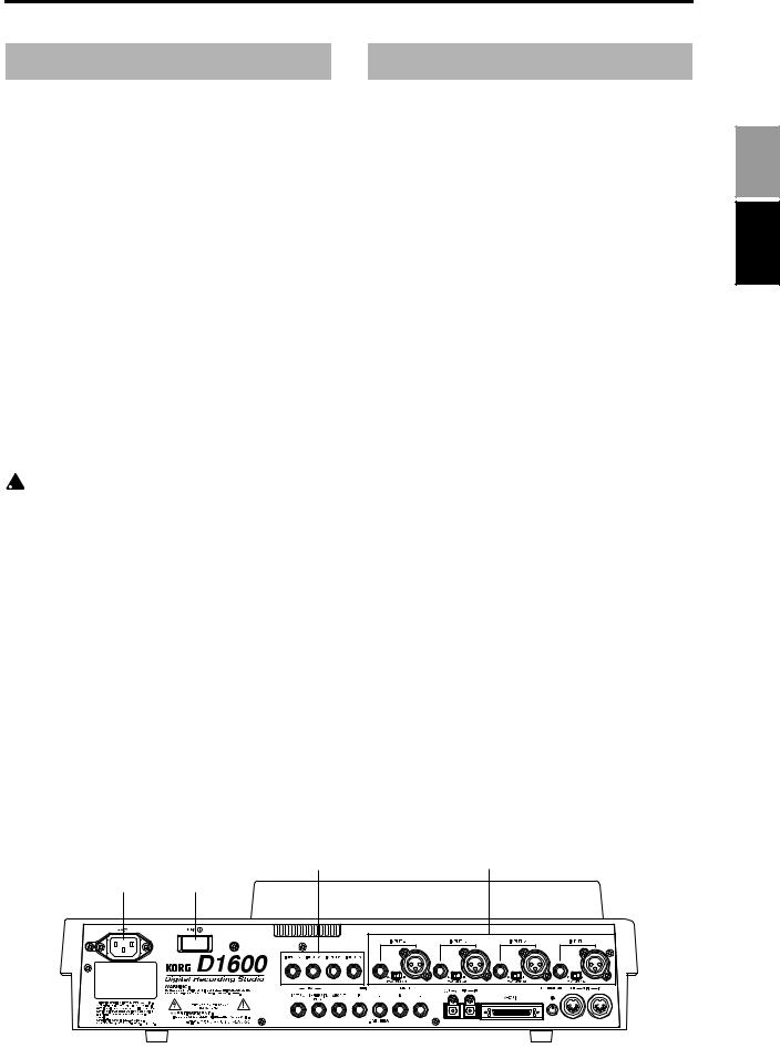
Rear panel
1[AC] connector
Connect the included power supply cable here.
2[Main power] switch
This turns the main power on/off. When the [Main power] switch is turned on, the D1600 will be in standby mode. In standby mode, you can press the [POWER] key to turn on the power of the D1600. While the D1600 is operating, you can use the [POWER] key to shut down, and then turn the main power off to turn the power off completely.
 To turn off the power, you must first press the
[POWER] key to perform the shutdown operation. Never turn off the [Main power] switch or disconnect the power cable until shutdown has been completed.
If you turn off the [Main power] switch or disconnect the power cable before shutdown has been completed, data and user settings may be lost, or the hard disk may be damaged.
3[INPUT 1], [INPUT 2], [INPUT 3], [INPUT 4] jacks
Audio sources such as mic or line (keyboard etc.) can be connected here.
These are combo-type balanced inputs that combine XLR jacks and 1/4" TRS phone jacks. Unbalanced phone plugs can also be connected. +48V phantom power is provided on the XLR jacks so that you can use condenser mics.
 Only one of the input jacks (XLR or 1/4") can be used at a time.
Panel overview of Introduction the D1600
Rear panel
4 |
3 |
1 2
|
|
|
|
|
|
|
|
|
|
|
|
|
|
|
|
|
|
|
|
|
|
|
|
|
|
|
|
|
|
|
|
|
|
|
|
|
|
|
|
|
|
|
|
|
|
|
|
|
|
|
|
|
|
|
|
|
|
|
|
|
|
|
|
|
|
|
|
|
|
|
|
|
|
|
|
|
|
|
|
|
|
|
|
|
|
|
|
|
|
|
|
|
|
|
|
5 6 |
7 |
8 |
|
9 |
|
10 11 |
12 |
13 14 15 |
|||||||||||||||||||
11
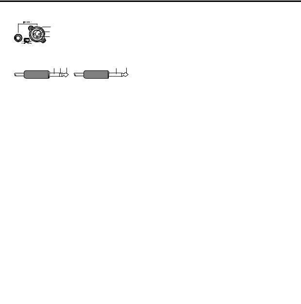
2: HOT 1: GND 3: COLD
 Phantom power switch
Balanced phone plug |
|
Unbalanced phone plug |
|
GND COLD HOT |
GND |
HOT |
|
Phantom power switch: [INPUT 1–4] jacks provide +48V phantom power so that condenser mics can be used. Phantom power is supplied to the balanced XLR jacks, and can be switched independently for each channel. Turn this switch on only for channels that use a condenser mic.
 If a condenser mic is connected or disconnected with the phantom power switch on, damage to your equipment may occur. For this reason, always turn the phantom power switch off before connecting a condenser mic.
 Never connect an unbalanced mic or device when the phantom power switch is on. Doing so may damage your equipment.
4[INPUT 5], [INPUT 6], [INPUT 7], [INPUT 8] jacks
Mic/line (e.g., keyboard) sources can be input here. These are balanced 1/4" TRS phone jacks. Unbalanced phone jacks can also be connected.
 If you connect a plug to the [GUITAR IN] jack, no input signal will be received from the [INPUT 8] jack. If you wish to use the [INPUT 8] jack, disconnect the plug from the [GUITAR IN] jack.
5[FOOT SW] jack
When your hands are occupied with playing an instrument, you can use a foot switch to control basic operations of the D1600 recorder.
A foot switch can be used to start/stop the play-
back, start/end manual punch-in recording, register a mark, or to record tap tempo. (→ p.75) Connect the foot switch (optional PS-1) to this jack.
6[EXPRESSION PEDAL] jack
You can use a pedal to control a specified parame-
ter of an insert effect. You can control the parameter in realtime while you play or record. (→ p.47) Connect an expression pedal (separately sold option, EXP-2, XVP-10 etc.) to this jack.
7[AUX OUT] jack
Connect this to the input jack of an external effect device.
This jack outputs the external send signal from each mixer channel. (→ p.47)
This is a 1/4" phone jack.
8[MONITOR OUT L/R] jacks
Connect your external monitor system to these jacks. The bus that is sent to the monitor output is
selected in the [SOLO/MONITOR] “Monitor” tab page. (→ p.109) These jacks output the same audio signal as [PHONES].
This is a 1/4" phone jack.
9[MASTER OUT L/R] jacks
These are analog outputs for the master LR bus which combines the signals from each mixer channel, or for the audio source that is selected by the Solo function. The Solo selection is made in the [SOLO/MONITOR] “Solo” tab page.
Connect your external monitor system or recording device to these jacks. They output the same audio signal as the [S/P DIF OUT] jacks.
This is a 1/4" phone jack.
10[S/P DIF OUT] jack
This is an optical-type S/PDIF format (IEC60958, EIAJ CP-1201) digital output jack (stereo).
Use an optical cable to connect this jack to the optical digital input of your DAT or MD.
This jack digitally outputs the same audio signal as the [MASTER OUT L/R] jacks at a sampling rate of
44.1kHz.
11[S/P DIF IN] jack
This is an optical-type S/PDIF format (IEC60958, EIAJ CP-1201) digital input jack (stereo).
Use an optical cable to connect this jack to the optical digital output of your DAT or MD.
A sampling rate converter is built in. If the connected source has a sampling rate of 48 kHz or 32 kHz source, it will be converted automatically to
44.1kHz.
12[SCSI] connector
An external hard disk drive, or removable disk drive can be connected here, and used for recording/playback in the same way as the internal
drive. An external drive can also be used for backup. (→ p.67)
In addition, a CD-R/RW drive can be connected
here to create an audio CD or to make backups. (→ p.49, 67)
This is a HD SCSI-2 (50 pin SCSI) connector.
 For details on the SCSI devices that can be used with the D1600, please contact your Korg distributor
13[LCD CONTRAST] knob
This adjusts the contrast of the LCD screen. The optimal setting will depend on the viewing
angle, so adjust the contrast as necessary. Looking from the front panel, turning the knob toward the right will darken the text, and turning it toward the left will lighten the text.
14[MIDI OUT] connector
MIDI messages are transmitted from this connec-
tor. Use this when you wish to control a connected external MIDI device from the D1600. (→ p.73)
15[MIDI IN] connector
MIDI messages are received at this connector. Use
this when you wish to control the D1600 from a connected external MIDI device. (→ p.73)
12
Objects in the LCD screen and their functions
Objects in the LCD screen
The LCD screen of the D1600 features the Touch View system, which uses a touch panel.
By pressing objects displayed in LCD screen you can perform operations such as selecting pages, setting parameter values, moving the cursor location, or editing settings.
In this manual, terms enclosed in “quotation marks” such as “...”, “...” button, or “...” tab refer to objects in the LCD screen which you can operate. Terms enclosed in square brackets such as [...] key, [...] knob, [...] dial, or [...] fader refer to controls etc. located on the top panel, front panel, or rear panel.
a:Current parameter |
c:Popup |
d:Toggle |
||||||
display |
|
|
button |
|
button |
|||
|
|
|
||||||
|
|
|
|
|
|
|
|
|
|
|
|
|
|
|
|
|
|
|
|
|
|
|
|
|
|
|
|
|
|
|
|
|
|
|
|
|
|
|
|
|
|
|
|
|
|
|
|
|
|
|
|
|
|
e: Tab |
b: Edit cell |
a: Current parameter display
This is the name of the parameter currently selected by the edit cell.
For icon-type parameters such as EQ or fader, the value is displayed at the right.
b: Edit cell
When you select a parameter in the LCD screen, the parameter value will be highlighted in some cases. This area is referred to as the edit cell, and your editing will apply to the highlighted portion.
The parameter value in the edit cell can be modified using the [VALUE] dial (→ p.8) or by using the popup buttons in the LCD screen.
c: Popup button
When you press this button, a dialog box (f) will appear.
To enter a parameter value, choose the desired value from the dialog box.
 ,
,  ,
, 
d: Toggle button
Pressing this type of button will alternately switch a function between on/off.
 (on)/
(on)/ (off)
(off)
e: Tab page
Each mode contains numerous parameters, which are organized into pages. Each page is accessed by its own tab.
f: Dialog box
To execute, press the “OK” button. To cancel, press the “Cancel” button. The dialog box will close.
g: Radio buttons |
f: Dialog box |
g: Radio buttons
These buttons are used to select one of multiple items. Press one of the radio buttons.
h: Icons
These are objects shaped like faders or knobs. To modify a value, select it and rotate the [VALUE] dial.
h:Icons
i:Scroll buttons
These buttons are used to view parameter values that cannot be displayed in a single screen.
i: Scroll buttons
Introduction
in the LCD screen and |
their functions |
Objects |
|
|
|
13

Adjusting the LCD screen contrast
Use the rear panel [LCD CONTRAST] knob to adjust the contrast. (→ p.12)
Basic operation
1. Selecting a mode
To make settings in the LCD screen for the various functions of the D1600, you must first press the key of the mode that includes that function.
For the functions of each mode, refer to “Reference” (→ p.75–).
2. Selecting a tab page
Each mode contains numerous parameters, and these are organized into pages. Pages are accessed by tabs.
1Press the key for the desired mode.
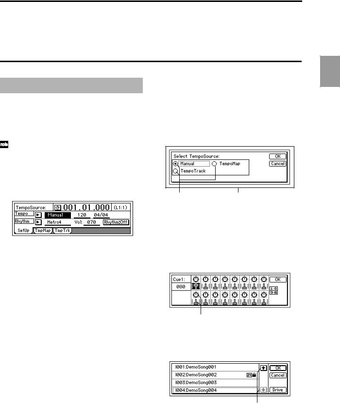
The illustration below shows a tab page of TEMPO/RHYTHM mode that will appear when you press the [TEMPO/RHYTHM] key.
 In this manual, this is referred to as the [TEMPO/ RHYTHM] “SetUp” tab page.
2Select the desired tab page.
Each time you press the key of the currently selected mode, you will cycle through the tab pages of that mode.
Some pages contain only one tab.
3. Selecting and setting a parameter
Selecting a parameter
Use one of the following methods to select the parameter that you wish to edit.
•In the LCD screen, press that parameter directly.
•Press the up/down/left/right areas of the [CURSOR] key to move the cursor to that parameter.
•In a list display screen, rotate the [VALUE] dial to move the cursor.
Setting a parameter value
The method of setting a parameter value will differ depending on the type of parameter.
Underlined “___” parameters, and icons such as EQ
Either directly press the parameter displayed in the LCD, or use the [CURSOR] key to move the edit cell so that the parameter is highlighted, and rotate the [VALUE] dial to edit the value.
This is the typical method, and also applies for underlined parameters such as “Tempo”, parameters displayed as an icon such as EQ, and changes in locate times.
Popup buttons and dialog boxes
Use the popup button to access the dialog box, and set the parameter value (→ p.13).
•When you press a popup button shown in the LCD screen, a dialog box will appear.
•Use the [CURSOR] key to move the edit cell to the popup button, and press the [ENTER] key to access the dialog box.
Toggle buttons
These buttons are used to turn a function on/off. (→ p.13)
•Each time you press a toggle button shown in the LCD screen, the setting will alternate on/off.
•Use the [CURSOR] key to select the parameter, and press the [ENTER] key. The button will turn on/off each time you press it.
Radio buttons
These buttons are used to select one of multiple choices.
•When you press one of the radio buttons shown in the LCD, it will be selected.
•Use the [CURSOR] key to move the edit cell to the desired button, and press the [ENTER] key.
Selecting an item from a list
•To select a song or mark, rotate the [VALUE] dial to select the desired item.
•To select a song in a program play list, use the following procedure.
1 Select the playback list num.
2 Rotate the [VALUE] dial to select the song.
14
Basic operation
Step 0. Starting
1. Preparations
Included items
Make sure that the following included items are all present.
• Operating manual (this document)
Owner’sManual
E 1
• Demo CD
• Power cable
Before using the D1600 for the first time
The D1600 will not operate unless an internal hard disk is installed.
Before using the D1600 for the first time, you must install an internal hard disk.
You must install either a separately sold Korg HDD20G hard disk or a Korg-recommended product. Refer to p.134 “About the internal hard disk.”
 For a list of hard disks recommended by Korg, please contact your Korg distributor.
2. Using the D1600
The D1600 lets you record your own performance and shape it into a completed song.
If a CD-R/RW drive such as the CDRW-2 is installed in the D1600, you will also be able to easily create your own original CD’s.
Connecting instruments and turning on the power
Connect the instrument and mic etc. that you wish to use for recording to the D1600, and turn on the power. (→ p.17)
Create a song
First you will create a song, and assign a song title.
If you will be creating a CD, set the song type to 16 bit. The title can be assigned later. (→ p.21)
Recording
Successively record the melody, bass, and drums etc. on tracks 1–16.
This process is the same as when using analog tape multi-track recorders, but the important difference is that on the D1600, you can use numerous convenient functions, such as the Undo function to cancel a mistake you made, the Auto Punch-in/out function to rerecord a specific area that you wish to fix, or Trigger Recording to automatically start recording as soon as you begin playing your instrument. You can also take advantage of the D1600’s virtual tracks to record and edit using more than 16 tracks. In addition, you can use the internal rhythm sounds as a tempo guide, or apply the internal effects as you record. (→ p.27)
Mixdown
In this step, you can apply EQ and effects to the sound of each recorded track, adjust the volume and pan, and combine the tracks into two tracks. (→ p.49)
By applying the built-in Final Effect to the MASTER L/ R, you can add finishing touches to your song. When you have finished adjusting the balance, use “16Tr → 2Tr bounce” to mix the song down to two tracks.
At this time if you record the mixdown on virtual tracks other than the current virtual tracks (i.e., the tracks selected for recording and playback), you will be able to record and compare between up to seven different mixdowns. (→ p.30)
15
Basic operation |
|
|
|
Starting |
|
|
|
|
|
connections, and |
the power on/off |
Making |
turning |
|
|
Creating/selecting |
a song |
|
|
|
|
Assign audio inputs |
to the mixer |
|
|
|
|
Recording |
|
|
|
|
|
Playback |
|
|
|
|
|
Changing the |
time location |
|
|
|
|
Using the mixer |
|
|
|
|
|
Using effects |
|
|
|
|
|
Mixdown |
|
|
|
|
|
Track editing |
|
|
|
|
|
Song editing |
|
|
|
|
|
Rhythm/tempo settings |
|
|
|
|
|
Saving your data |
|
|
|
MIDI |
|
|
|

Writing your song to CD
In this step, the song that was mixed down to tracks 1 and 2 is turned into a CD.
Play back the mixed down tracks 1 and 2 to check them. These tracks (1 and 2) will be written to the CD. Then simply insert a new CD-R disc into the drive, and press the “WriteToCD” button to write the data to CD.
By using the same procedure to create additional songs and writing them to CD, you can create a CD album. When you are finished, press the “Final” button to finalize the disc and complete your very own original CD. (→ p.49)
|
|
|
|
|
|
|
|
Connect |
→ |
Step 1 |
|
||
|
instruments and |
|
|
|
||
|
turn on the power |
|
|
|
||
|
|
|
|
|
|
|
|
|
|
|
|
|
|
|
|
|
|
|
|
|
|
|
|
|
|
|
|
|
Create a new song |
→ |
Step 2 |
|
||
|
|
|
|
|
|
|
|
|
|
|
|
|
|
Record
Assign mixer channels |
→ Step 3 |
|
•Apply effects to the input sound (Step 8)
•Apply EQ
Recording → Step 4 |
|
Overdubbing → Step 4 |
|
Adjust the recording level |
|
|
|
|
|
|
|
|
|
|
|
Playback |
|
→ |
Step 5 |
|
|
|
|
|
|
|
|
|
|
Editing |
→ |
|
Step 10 |
|
|
|
|
|
|
|
|
|
|
• Track editing |
|
|
|
|
|
|
• Punch-in/out |
|
|
|
|
|
|
Mixdown |
|
|
|
|
→ |
Step 9 |
Adjust the track balance |
|
→ |
Step 7 |
|||
• Apply effects to the tracks |
|
|
|
|||
• Apply EQ to the tracks |
|
|
|
|||
• Apply master effects |
|
|
|
|||
Final effect |
|
→ Step 8 |
Scenes |
→ |
Step 7 |
|
|
|
|
|
|||
|
|
|
|
|
|
|
|
|
|
|
• Registering a scene |
||
|
|
|
|
• Playing a scene |
||
Bounce to tracks 1 and 2 |
|
|
|
|||
|
|
|
→ Step 4 |
|
|
|
Creating an audio → Step 9
Write the song to CD
Finalize
16

Step 1. Making connections, and turning the power on/off
1. Connections
The diagram below shows a basic example of connections when using the D1600 to record. Make the appropriate connections for your system, substituting your own equipment as necessary for the equipment shown here.
 For details on installing the HDD-20G hard disk drive option or the CDRW-2 CD-R/RW drive option, refer to p.134.
 Be sure that the power is turned off while you are making connections. If the power is on while connections are being made, your speaker system may be damaged, or other malfunctions may occur.
1Connect the included power supply cable.
Connect the power supply cable to the D1600’s [AC] connector. Then plug the other end into an electrical outlet.
2Connect your audio monitoring system.
Use a phone cable to connect powered monitors etc. to the [MONITOR OUT L/R] jacks.
If you will be monitoring through headphones, connect the 1/4" phone plug of your headphones to the [PHONES] jack.
Use the [PHONES LEVEL] knob to adjust the volume.
[PHONES] jack [PHONES LEVEL] knob
 The audio signal that is output from the [MONITOR OUT L/R] jacks and the [PHONES] jack is set in the [SOLO/MONITOR] “Monitor” tab page.
(→ p.109)
Master recorder (Analog: cassette tape recorder, etc.)
|
|
INPUT L/R |
|
|
|
|
MASTER |
Master recorder (Digital: DAT, MD, etc.) |
OUT L/R |
||
|
DIGITAL IN |
|
|
|
|
S/P DIF OUT |
|
|
DIGITAL OUT |
|
|
|
|
S/P DIF IN |
|
INPUT |
INPUT |
|
|
1–8 |
|
||
1–4 |
|
|
|
|
|
|
|
Hard disk drive, CD-R/RW drive removable disk drive (MO, zip, jaz etc.)
 SCSI
SCSI
Powered monitors etc.
|
|
MIDI |
|
|
sequencer |
|
|
MIDI |
|
MIDI |
OUT/IN |
|
|
|
|
IN/OUT |
to the AC outlet |
SCSI |
MONITOR |
|
|
AC connector |
|
|
OUT L/R |
OUTPUT |
Mic |
Keyboard |
Basic operation
connections, and |
the power on/off |
Making |
turning |
|
|
GUITAR IN |
PHONES |
HDD-20G |
CDRW-2 |
Guitar |
|
||
|
|
Hard disk |
CD-R/RW |
|
|
drive option |
Drive option |
Headphones
17
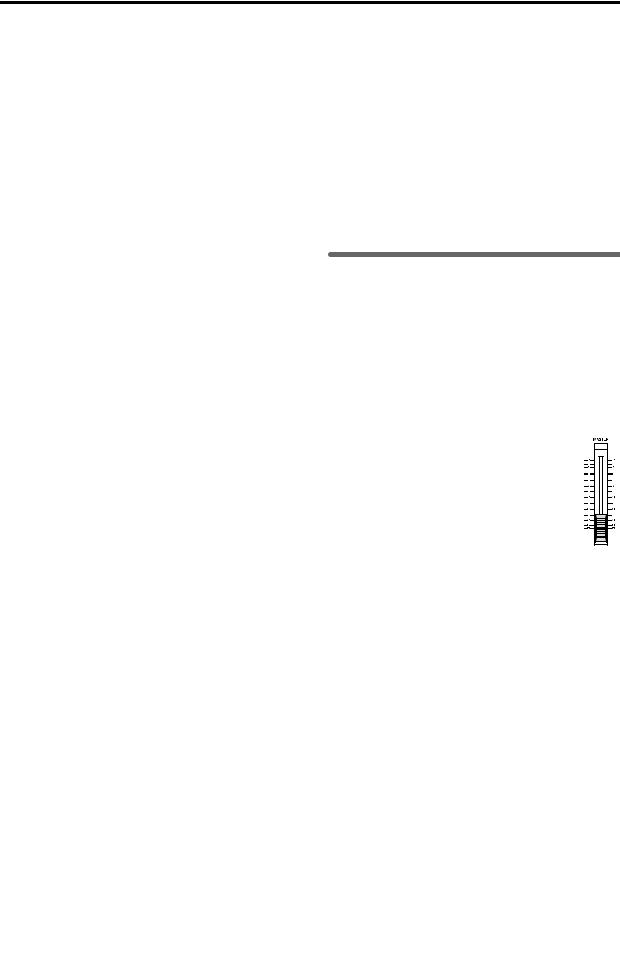
3Connect your input devices.
Connections for recording analog sources
•Guitar, bass guitar ↔ [GUITAR IN] jack
•Mic (XLR) ↔ [INPUT 1]–[INPUT 4] jacks
•Synthesizer etc. ↔ [INPUT 1]–[INPUT 8] jacks For details on assigning the audio inputs to mixer channels and auditioning the input sound, refer to p.23.
 A guitar or bass guitar that is being sent through a compact effect device can be connected to [INPUT 1]–[INPUT 8].
 When inputting in stereo, you should select two adjacent inputs (1–2, 3–4) so that track editing can be performed more efficiently.
 If you are recording from a connected mic, locate the mic at a sufficient distance from the D1600 so that it does not pick up noise.
Connections for recording digital sources
•Optical digital (S/P DIF) output of a digital output device such as DAT or MD [S/P DIF IN] jack
of the D1600 (use an optical digital cable for connection)
For details on assigning the audio inputs to mixer channels and auditioning the input sound, refer to p.23.
4Make other connections.
Connections for mixdown
Here’s how to make connections when the song created on the D1600 will be mixed down on an external recording device (DAT, MD, tape recorder, etc.)
•Optical digital (S/P DIF) input of a digital recording device such as DAT or MD ↔ [S/P DIF OUT] of the D1600
•AUX IN inputs of an analog recording device such as a cassette tape recorder ↔ [MASTER OUT L/R] jacks of the D1600
Connections when using external effects
If you wish to apply an external effect to the signal from [AUX OUT] send output, use the [INPUT 1]– [INPUT 8] jacks to receive the return signal(s).
In this case, you can choose whether the signal(s) will be returned to the mixer channel(s) in the same way as a conventional input, or sent directly to the master bus. (→ p.48)
Connections when using a foot switch to perform manual punch recording, or playback/stop etc.
Connect the pedal switch (separately sold option: PS-1) to the [FOOT SW] jack.
Connections when using a foot pedal to control effects
Connect the expression pedal (separately sold option: EXP-2, XVP-10) to the [EXPRESSION PEDAL] connector.
 If a volume pedal is connected, it will not operate correctly.
Connections when controlling effects or switching scenes from an external MIDI device
Connect the MIDI OUT connector of the external MIDI device ↔ [MIDI IN] connector of the D1600. (→ p.73)
Connections when synchronizing the D1600 and a MIDI sequencer etc.
Connect the MIDI IN connector of the sequencer etc. ↔ [MIDI OUT] connector of the D1600. (use a MIDI cable)
Connect the MIDI OUT connector of the sequencer etc. ↔ [MIDI IN] connector of the D1600. (→ p.73)
Connections when saving or backing up data on an external hard disk or removable disk
SCSI connector of the external SCSI device ↔ [SCSI] connector of the D1600 (use a SCSI cable to make connections). (→ p.67)
2. Turning the power on/off
Turning the power on
Use the following procedure to turn on the power of the D1600 and of the devices connected to it.
 Before turning the power on, be sure to lower the volume of each device to the minimum position, and turn the devices on beginning with the first device in the signal chain (i.e., devices that produce audio signals).
1 Lower the D1600’s [MASTER] fader to the
– ∞ position. Also turn down the volume of each connected device.
2 Turn on the power of the external input device, such as a keyboard connected to the D1600. If an external drive is connected, turn on the power of the external drive.
3Turn on the [Main power] of the D1600.
The STANDBY LED will light. The D1600 will be in “standby” mode.
4Press the [POWER] key of the D1600 to turn on the power.
The opening message will appear in the LCD screen, and then the [SONG] “SelSong” tab page will appear. The selected song will be the one that had been selected when the power was last turned off.
5Turn on the power of your external equipment, such as the monitor system to which audio is being sent from the D1600.
Turning the power off
When you are finished playing or recording a song, turn off the power. If you will not be using the D1600 for an extended (e.g., when you have finished work for the day), be sure to turn off the main power so that the power is turned off completely. Use the following procedure to turn off the power of the D1600 and of the connected devices.
 Before turning off the power, turn the volume of all devices down to the minimum position, and turn off the power switches beginning with the devices that are at the end of the audio signal chain.
 When you wish to turn off the power, you must perform the shutdown operation. Never turn off the [Main power] switch or disconnect the power
18
cable until the shutdown has been completed. If you turn off the main power or disconnect the power cable before shutdown is complete, data or user settings may be lost, or you may damage the hard disk.
 Audio that is recorded on the D1600 and the mixer settings you make are saved automatically when you select or switch songs, or when you shut down. However, effects that you edit will be lost unless you save them.
1If you wish to keep any effect settings that you edited, save them. (→ p.46)
2Lower the [MASTER] fader of the D1600 to the –∞ position. Lower the volume of any external devices to the minimum position.
3Turn off the power of the external output devices (such as your monitor system) to which audio is being sent from the D1600.
4Press and hold the D1600’s [POWER] key to perform the shutdown operation.
When you press and hold the [POWER] key, a dialog box will appear, asking you to confirm the operation. If you press the “Yes” button, the song will automatically be saved and the D1600 will shut down and enter standby condition. If you press the “No” button, you will return to the previous screen.
5By pressing the D1600 [Main power] switch to turn it off, you can turn the power off completely.
6If an external drive is connected, turn off the power of the external drive.
7Turn off the power of external input devices, such as keyboards.
Listening to the demo song
The D1600 comes with a demo CD that contains demo songs. Here’s how to listen to the demo songs on the CD.
 This operation requires a separately sold CD-R/ RW drive (such as the CDRW-2).
 The included demo CD is different than conventional audio CD’s. Never attempt to use it in an audio CD player.
1Connect your CD-R/RW drive.
If you are using an internal CD-R/RW drive, install
the CD-R/RW drive in the CD-R/RW drive bay of the D1600. (→ p.134)
If you are using an external CD-R/RW drive, con-
nect the CD-R/RW drive to the SCSI connector of the D1600. (→ p.67)
2Restore (load) the demo songs from the demo CD into the D1600. (→ p.66: Backup/Restore)
3Move the D1600’s [CHANNEL] faders to the 0 mark, and the [MASTER] fader to the –∞ mark.
4Select the song that you wish to play back. (→ p.22)
5For each track, make the [TRACK STATUS] key LED light green. If any LED’s are lit another color, or are dark, press the corresponding key to make the LED light green (PLAY).
6 Press the [PLAY] key to begin playback.
7Slowly raise the [MASTER] fader to adjust the volume level.
8When the demo song ends, press the [STOP] key to stop playback.
Basic operation
connections, and |
the power on/off |
Making |
turning |
|
|
19

20
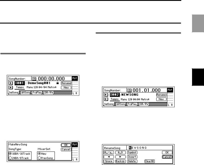
Step 2. Creating/selecting a song
In order to record a new song, you must first create a new song. Here’s how to create a song, assign a name to it, and select songs.
1. Creating a new song
1Press the [SONG] key to access the “SelSong” tab page.
2. Naming a song
Now you can assign a name to the newly created song.
We recommend that you assign a name to the song before recording it, so that it can be distinguished from other songs.
If you wish to change the name of another song, select that song before you begin the following procedure. (→ “3. Selecting another song”)
1Press the [SONG] key to access the “SelSong” tab page.
2Press the “New” button.
The “MakeNewSong” dialog box will appear.
3Select the quantization bits/number of tracks for the song that will be created, and select the mixer settings.
Use the “SongType” radio buttons to select the
number of bits and tracks. Set the “MixerSet” radio buttons in the same way. (→ p.89 “SongType,” “MixerSet”)
4Press the “OK” button.
A song named “NEWSONG” will be created following the last song that currently exists.
For details on deleting a song, refer to p.60.
2Press the “Rename” button.
The “RenameSong” dialog box will appear.
3Modify the song name.
Use the “  “ “
“ “  ” buttons to move the cursor in the song name to the character that you wish to change, and rotate the [VALUE] dial to modify the name.
The buttons in the LCD screen have the following function.
“A../a..”: Select alphabetical characters (e.g., “A”). Press the button once again to select lowercase alphabetical characters (e.g., “a”).
“0...9”: Select numerals (e.g., “0”). “Symbol”: Select symbols.
“Insert”: Insert a space and move the subsequent characters backward.
“Space”: Select a space (blank).
“Backsp”: Delete the character before the cursor location.
“Delete”: Delete the character at the cursor location.
“ClearAll”: Erase the entire name.
4Finalize the name.
If you are satisfied with the name you input, press the “OK” button. To cancel without changing the name, press the “Cancel” button.
Basic operation
Creating/selecting a song
21

3. Selecting another song
This section explains how to select songs. There are three ways to select an existing song.
[STOP] key + [FF] key, [STOP] + [REW] key
Use this method to select the song of the previous or next number on the same drive.
•Hold down the [STOP] key and press the [FF] key to move to the end of the current song. Press these keys once again to move to the beginning of the next song.
•When you hold down the [STOP] key and press the [REW] key, you will move to the beginning of the previous song if you were already at the beginning of the song (e.g., “000:00.000”). If you were at a location during the song, you will move to the beginning of that song.
Move the edit cell to the song number, and rotate the [VALUE] dial
Use this method to select another song in the same drive.
1Press the [SONG] key to access the “SelSong” tab page.
2Select “SongNumber” (it will be highlighted), and rotate the [VALUE] dial to select the song num.
Select from the song list (Selecting a song from another drive)
Use this method to select another song in the same drive, or to select a song from another drive.
1Press the [SONG] key to access the “SelSong” tab page.
2Press the “  ” button at the left of the song number.
The song list will appear.
3Rotate the [VALUE] dial to select a song in the song list. Then press the “OK” button.
To change the drive
To change the drive, press the “Drive” button and select a drive from the list. Press the “OK” button to return to the song list.
Drive ID
Each connected drive is assigned a different “Drive ID” according to its SCSI ID.
I: Internal IDE (internal drive) A–G: SCSI ID numbers 0–6
 If a separately sold CD-R/RW drive is installed, it will automatically be assigned to “G”.
If you connect a CD-R or CD-RW drive to the [SCSI] connector, set the SCSI ID of the drive to “6” (assigning it to “G”). A hard disk drive can also be assigned this number.
 If a CD-ROM drive, a CD-R or CD-RW drive, or a hard disk set to “Drive ID” “G” is connected to the [SCSI] connector, the internal CD-RW drive option cannot be used.
Device Type, Total Size
This shows information on the drive (type and capacity).
HDD: Hard Disk Drive RMD: Removable Disk Drive CD: CD-ROM, CD-R, CD-RW
*Removable disk drive is a collective term for drives from which the disk can be removed, such as MO, Zip, or Jaz.
Format Type
This shows the format type of the drive. Internal drives of the D1600 and external drives formatted or initialized while connected to the D1600 will be displayed as [P] or playback drive, which can be used to record songs. Other drives will be displayed as [B] or backup drives which you can backup and restore songs from.
22

Step 3. Assign audio inputs to the mixer
The D1600 provides eight channels of analog input and one (two-channel) digital input jack. In order to record the audio signals from these inputs, they must be assigned to mixer channels. If the CDRW-2 CD-R/RW drive option (sold separately) is installed, you can also assign the signal from an audio CD to the mixer channels.
*The audio of the internal CD-R/RW drive is connected as an analog signal.
Input1 |
|
Ch1: Track 1 |
|||
|
|||||
Input2 |
|
|
|||
|
Ch2: Track 2 |
||||
|
|||||
Input3 |
|
|
|||
Input4 |
|
Ch3: Track 3 |
|||
|
|
||||
Input5 |
|
Ch4: Track 4 |
|||
|
|
|
|
|
|
Input6 |
|
Ch5: Track 5 |
|||
Input7 |
|
|
|||
|
Ch6: Track 6 |
||||
Input8 |
|
|
|||
|
|
|
|
|
Ch7: Track 7 |
|
|
|
|
|
|
|
|
|
|
|
Ch8: Track 8 |
|
|
|
|
|
|
|
L |
|
Ch9: Track 9 |
||
Digital In |
|
|
|||
|
R |
|
Ch10: Track 10 |
||
|
|
|
|
|
|
|
L |
|
|
|
Ch11: Track 11 |
|
|
|
|
|
|
|
Dr |
|
|
|
Ch12: Track 12 |
|
|||||
|
R |
|
|
|
|
|
|
|
|
|
|
|
|
|
|
|
Ch13: Track 13 |
|
|
|
|
|
|
|
L |
|
Ch14: Track 14 |
||
|
CD |
|
|
||
|
R |
|
Ch15: Track 15 |
||
|
|
|
|
|
|
|
|
|
|
|
Ch16: Track 16 |
[INPUT]“Ch1-8”, “Ch9-16”
In this section we will explain how to assign each type of input source to mixer channels, and audition the source.
The D1600, the input mixer channel numbers are the same as the recording and playback track numbers. For example if you wish to record on track 8, you must assign the audio signal to mixer channel 8.
1. Analog inputs
Use the connections and settings most applicable to your situation.
•Connect a guitar to the [GUITAR IN] jack, and assign it to mixer channel 8
•Connect a condenser mic audio input source to [INPUT 2], and assign it to mixer channel 2.
•Connect a keyboard to the [INPUT 3] and [INPUT 4] jacks, and assign them to mixer channels 9 and 10
If you are using stereo input, you should use adjacent inputs (1–2, 3–4), and input the signals to adjacent mixer channels.
Before you proceed, create a new song as described in “1. Creating a new song” (→ p.21).
Connect a guitar to the [GUITAR IN] jack, and assign it to mixer channel 8
1Connect your guitar.
Set the [INPUT 8] ([GUITAR IN]) [TRIM] to the minimum (+4 dB) and lower the [MASTER] fader before connecting your guitar to the [GUITAR IN] jack.
2Select the input channel.
•Access the [INPUT] “Ch1–8” tab page.
•Select the “Ch8” icon, and rotate the [VALUE]
dial to select “INPUT 8.”
The input from the [GUITAR IN] jack has now been assigned to mixer channel 8.
3Assign the input sound to mixer channel 8.
Press the track 8 [TRACK STATUS] key to set it to INPUT (LED lit orange).
4Use the trim to adjust the input level.
Press the [METER/TRACK VIEW] key. Press the “  ” button to access the dialog box.
Press the “PreFaderLev” radio button, and press the “OK” button.
Play your guitar to input sound, and the level meter of Ch.8 will move accordingly. Adjust the INPUT 8 [TRIM] knob while watching the level meter. Raise the [TRIM] as high as possible without the level reaching CLP, while playing your guitar.
5Audition the sound.
•Set the [MASTER] and [CHANNEL 8] faders to unity gain (0 dB).
•Access the [SOLO/MONITOR] “Monitor” tab page.
•Press the “MasterLR” button to turn it “On” (highlighted).
•Gradually raise the [PHONES LEVEL] knob or [MONITOR OUT LEVEL] knob, and listen to the sound in your headphones or monitor system.
Basic operation
Assign audio inputs to the mixer
23
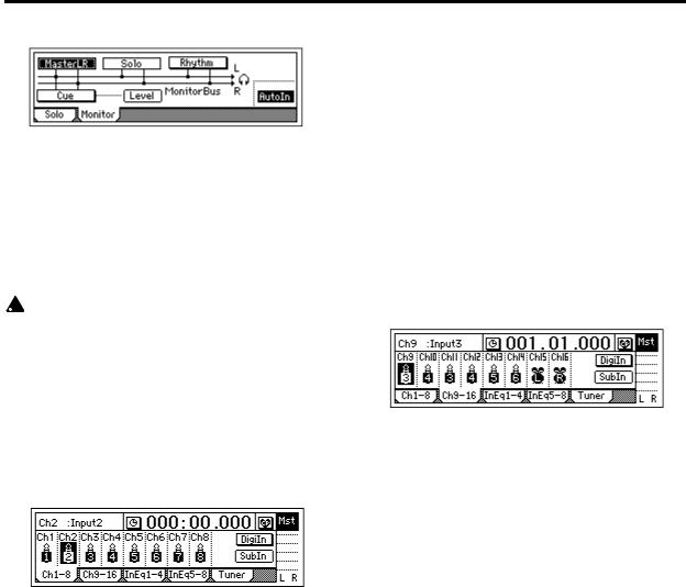
Connect a mic to [INPUT 2] and assign it to mixer channel 2
1Connect a mic.
Set the INPUT 2 [TRIM] to the minimum (+4 dB), lower the D1600’s [MASTER] fader, and connect a mic to the [INPUT 2] jack.
If you are using a condenser mic, turn on phantom power for [INPUT 2] after you connect the mic.
 Turn phantom power on only if you are using a condenser mic.
 Phantom power must be turned on after connecting the condenser mic. If you connect or disconnect the mic with phantom power turned on, your equipment may be damaged.
2Specify the input channel.
•Access the [INPUT] “Ch1–8” tab page.
•Select the “Ch2” icon, and rotate the [VALUE]
dial to select “INPUT 2.”
The input from the [INPUT 2] has now been assigned to mixer channel 2.
3Assign the input sound to mixer channel 2.
Press the track 2 [TRACK STATUS] key to select INPUT (the LED will light orange).
4Use trim to adjust the internal.
•Press the [METER/TRACK VIEW] key.
•Press the “  ” button to access the dialog box. Choose “PreFaderLev,” press the “OK” button.
•When you input sound into the mic, the Ch2 level meter will move accordingly.
•Adjust the input 2 [TRIM] knob while you watch the level meter. Raise the [TRIM] as high as possible. Don’t allow the level to reach CLP when you produce your loudest sound.
5Audition the sound.
•Set the [MASTER] and [CHANNEL 2] faders to unity gain (0 dB).
•Access the [SOLO/MONITOR] “Monitor” tab page.
•Press the “MasterLR” button to turn it “On” (highlighted).
•Gradually raise the [PHONES LEVEL] knob or [MONITOR OUT LEVEL] knob, and listen to the sound in your headphones or monitor system.
Connect a keyboard to the [INPUT 3] and [INPUT 4] jacks, and assign them to mixer channels 9 and 10.
1Connect your keyboard.
Set the [INPUT 3] and [INPUT 4] trim to the minimum (+4 dB) and lower the [MASTER] fader before connecting your keyboard to the [INPUT 3] and [INPUT 4] jacks.
2Select the input channels.
•Access the [INPUT] “Ch9–16” page tab.
•Select the “Ch9” icon, and rotate the [VALUE] dial to select “INPUT 3.”
•Select the “Ch10” icon, and rotate the [VALUE]
dial to select “INPUT 4.”
The input from the [INPUT 3] and [INPUT 4] jacks has now been assigned to mixer channels 9 and 10.
3Assign the input sound to mixer channels 9 and 10.
Press the track 9/10 [TRACK STATUS] keys to set each of them to INPUT (LED lit orange).
4Use the trim to adjust the input level.
•Press the [METER/TRACK VIEW] key.
•Press the “  ” button to access the dialog box. Choose “PreFaderLev,” press the “OK” button.
•Play your keyboard to input sound, and the level meters of Ch.9 and Ch.10 will move accordingly. Adjust the INPUT 3 and 4 [TRIM] knobs while watching the level meter. Raise the [TRIM] level as high as possible, don’t allow the level to reach CLP when you play your keyboard with maximum velocity.
5Audition the sound.
•Set the [MASTER], [CHANNEL 9] and [CHANNEL 10] faders to unity gain (0 dB).
•Access the [SOLO/MONITOR] “Monitor” tab page.
•Press the “MasterLR” button to turn it “On” (highlighted). Gradually raise the [PHONES LEVEL] knob or [MONITOR OUT LEVEL] knob, and listen to the sound in your headphones or monitor system.
24

2. Digital input
The D1600 can record a digital audio signal that is input via the S/P DIF jack.
The S/P DIF input has a built-in sampling rate converter. Sources with sampling rates of 48 kHz or 32 kHz can be connected directly, and will automatically be converted to 44.1 kHz.
Here we will explain how the audio from a DAT connected to the [S/P DIF IN] jack can be input to mixer channels 1 and 2.
1Connect the digital output device.
Lower the [MASTER] fader of the D1600, and use an optical digital cable to connect the digital output of your DAT to the [S/P DIF IN] jack.
2Enable the digital input.
•Access the [INPUT] “Ch1–8” tab page.
•When you press the “DigiIn” button, a message of “Obey Copyright Rules” will appear.
Carefully read the owner’s manual section “COPYRIGHT WARNING” (→ p.1). If you accept the terms, press the “Yes” button for the “AreYouSure?” prompt. Digital input will be enabled.
3Specify the input channels.
Select the “Ch1” icon, and rotate the [VALUE] dial to select “S/PDIF L.” In the same way, select “S/ PDIF R” for “Ch2.”
The input from the [S/P DIF IN] jack has now been assigned to channels 1 and 2.
4Assign the input sound to mixer channels 1 and 2.
Play back the DAT, and press the [TRACK STATUS] keys of tracks 1 and 2 to set them to INPUT (LED lit orange).
5Check the recording mode and input level, and audition the sound.
Refer to steps 3, 4, and 5 of “Connect a guitar to the [GUITAR IN] jack, and assign it to mixer channel 8.”
3. Using the tuner
Here’s how you can tune a sound that is being input.
1Use “SelectSource” to select the source that you wish to tune.
•If you wish to tune an instrument such as a guitar, connect the instrument to the [INPUT 8/ GUITAR IN] jack.
•In the [INPUT] “Tuner” tab page, set “SelectSource” to “Input8.”
2 Set “Calib” to specify the reference frequency.
3Adjust or measure the pitch.
The “Note Display” shows the note name, and the “CENT Scale” shows the pitch.
•If you selected “Input8,” play your instrument to produce sound, and tune it so that the central triangle is displayed as “▼.”
To measure the pitch of a previously-recorded sound
•To measure the pitch of a previously-recorded track, set “SelectSource” to “Track,” and choose the track that you wish to measure. Move to the time location that you wish to measure, press the [PLAY] key to play back, and measure the note name and pitch.
Basic operation
Assign audio inputs to the mixer
25

26
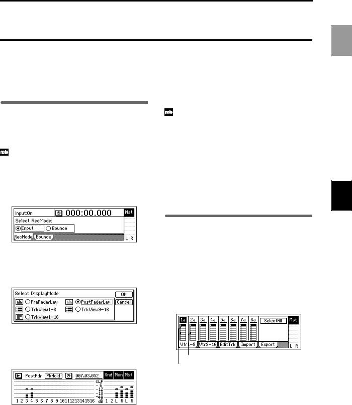
Step 4. Recording
This section explains the basic recording procedure on the D1600.
During recording, the audio signal flows in the order of input → mixer channel → recorder.
1.Adjust the recording level, and record
Here’s how to record the audio that you specified in “Assign audio inputs to the mixer” (→ p.23).
If you wish to create a new song and record into it,
refer to “1. Creating a new song” (→ |
p.21). Make |
sure that the [RHSL] key is Off. (→ |
p.112) |
1Check the recording mode.
Access the [RECORD] “RecMode” tab page. Set “Select RecMode” to “Input” (i.e., the audio input will be recorded).
5Start recording.
Press the [PLAY] key. (The [REC] and [PLAY] LEDs will light.)
Begin playing.
6Stop recording.
When you have finished playing, press the [STOP] key. (The [REC] and [PLAY] LEDs will turn off.)
When you have finished recording, verify that the performance was recorded correctly.
7 Move to the beginning of the song (→ p.35).
8Specify the track(s) for playback.
Press the [TRACK STATUS] key of the track you recorded, to set its status to PLAY (LED lit green).
9Begin playback.
Press the [PLAY] key. (The [PLAY] LED will light.)
0Stop playback.
When you are finished playing back, press the [STOP] key. (The [PLAY] LED will turn off.)
Use the [CHANNEL] fader to set the recording level.
•Press the [METER/TRACK VIEW] key.
•Press the “  ” button to select “PostFaderLev,” and press the “OK” button.
•Gradually raise the [CHANNEL] fader, and the level meter of the input channel will change according to the input. Raise the level as far as possible without allowing the level bar to reach “CLP.”
2Move the current time to the location where you wish to begin recording. (→ p.35)
Start recording from the beginning of the song (“001.01.000” or “000:00.000”).
3Press the [TRACK STATUS] key of the track that you wish to record, to set the status to REC (LED lit red).
4Enter record-ready mode.
Press the [REC] key. (The [REC] and [PLAY] LEDs will blink.)
2. Recording on virtual tracks
The D1600 has sixteen tracks, and each of these tracks has eight virtual tracks.
For example when recording a solo part, you can switch between several virtual tracks to record different performances on each, and select the best performance later. Or when using bounce (ping-pong) recording, you can specify an unrecorded virtual track as the recording destination, so that you can mixdown into two tracks without erasing any of the sixteen tracks. (→ p.29)
Recorded tracks
Selected track
Recording on a virtual track
1Select the virtual track.
In the [TRACK] “Vtr1–8” or “Vtr9–16” tab page, select the track that you wish to record, and use the [VALUE] dial to select an open virtual track.
2Adjust the recording level of the input device, and record.
Refer to “1. Analog inputs” and “1. Adjust the recording level, and record” (→ p.23).
Basic operation
Recording
27

3.Playback while recording addition tracks: Overdubbing
The process of listening to previously-recorded tracks while you record additional tracks is called overdubbing. For example, this can be used to record a solo while you listen to previously-recorded backing tracks.
1Select the playback tracks.
Press the [TRACK STATUS] keys of the tracks that you wish to play back, to set them to PLAY mode (LED lit green).
2Select the recording track.
Press the [TRACK STATUS] key of the track that you wish to record, to set it to REC mode (LED blinking red).
3Lower the faders of tracks you are not using.
Press the [TRACK STATUS] key of the tracks that are not being recorded or played, to set them to MUTE (LED dark). This will silence the tracks that are not being recorded or played.
4Adjust the recording level of the input device, and record.
Refer to “1. Analog inputs” and “1. Adjust the recording level, and record” (→ p.23, 27)
 In the [RECORD] “RecMode” tab page, set “Select Rec Mode” to “Input.”
4.Re-record part of a performance: Punch-in/out
If you make a mistake during part of your recorded performance, or are not completely satisfied with your performance, you can re-record just the unsatisfactory portion without having to record from the beginning of the song.
“Punch-in” is when you switch the song from playback to record, and “punch-out” is when you switch the song from record back into playback.
Manual punch-in/out
Manual punch-in/out is when you manually switch between punch-in and punch-out.
On the D1600, manual punch-in/out can be performed by pressing the [REC] key or a PS-1 foot switch (separately sold option) during playback to begin recording, and pressing the [REC] key, [PLAY] key, or foot switch to end recording.
1Connect the input device, and adjust the recording level.
Refer to “1. Analog inputs” and “1. Adjust the recording level, and record” (→ p.23, 27).
2Make monitor output settings.
•Access the [SOLO/MONITOR] “Monitor” tab page.
•Select the signal that you wish to monitor. (→ p.110)
•Turn the “AutoIn” button “On.” (→ p.110)
If the “AutoIn” button is “Off”, you will always hear the input signal that is assigned to the recording track. If it is “On”, the sound recorded on that track will be heard during playback, and the assigned input signal will automatically be heard during recording.
3Move the current time to a location earlier than
the point where you wish to begin re-recording. (→ p.35)
4Press the [PLAY] key to begin playback.
The song will play back, and you will hear the sound of the playback tracks and the track selected for recording.
5At the point where you wish to begin re-record- ing, press the [REC] key.
Recording will begin (manual punch-in), and you will begin hearing the external input signal.
6At the point where you wish to stop re-recording, press the [REC] key or [PLAY] key.
Recording will stop, and the track will switch back to playback (manual punch-out). You will begin hearing the track playback.
7Press the [STOP] key to stop.
After recording, move the current time to a point earlier than where you began recording, and check that the recording was satisfactory.
Manual punch-in/out using a foot switch
You can switch between playback and recording by pressing a PS-1 foot switch (separately sold option). This allows you to switch between playback and recording while you are performing on an instrument, or when you are at a distance from the D1600.
1 Connect a foot switch to the [FOOT SW] jack.
2 Access the [SYSTEM] “Control” tab page.
3Specify the function of the foot switch.
Select “Func (FootSwFunction)” to “PunchI/O.”
4In “Manual punch-in/out” steps 5 and 6, perform manual punch-in/out by pressing the foot switch instead of the [REC] key (you may use either).
You can also use the foot switch to record from the beginning of the song.
•Set the “Func” parameter of step 3 to “Play/ Stop.”
•Press the [REC] key at the beginning of the song (LED will blink), and press the foot switch to start recording.
28
 Loading...