


Kohler CV493, CV13, CV15, CV11-16, CV460-465 Manual
...
SERVICE MANUAL
COMMAND CV11-16,
CV460-465,
CV490-495
VERTICAL CRANKSHAFT
1

Contents
1
Section 1. Safety and General Information ............................................................................
2
Section 2. Special Tools ..........................................................................................................
3
Section 3. Troubleshooting .....................................................................................................
4
Section 4. Air Cleaner and Air Intake System ........................................................................
5
Section 5. Fuel System and Governor ....................................................................................
6
Section 6. Lubrication System ................................................................................................
7
Section 7. Retractable Starter .................................................................................................
8
Section 8. Electrical System and Components .....................................................................
9
Section 9. Disassembly ...........................................................................................................
10
Section 10. Inspection and Reconditioning ...........................................................................
11
Section 11. Reassembly ...........................................................................................................

SectionCV11-16
Safety andCV460General-465,InformationCV490-495
1
Section 1
Safety and General Information
Safety Precautions
To insure safe operations please read the following statements and understand their meaning. Also refer to your equipment manufacturer's manual for other important safety information. This manual contains safety precautions which are explained below. Please read carefully.
WARNING
Warning is used to indicate the presence of a hazard that can cause severe personal injury, death, or substantial property damage if the warning is ignored.
CAUTION
Caution is used to indicate the presence of a hazard that will or can cause minor personal injury or property damage if the caution is ignored.
NOTE
Note is used to notify people of installation, operation, or maintenance information that is important but not hazard-related.
For Your Safety!
These precautions should be followed at all times. Failure to follow these precautions could result in injury to yourself and others.
 WARNING
Accidental Starts can cause severe injury or death.
Disconnect and ground spark plug leads before servicing.
Accidental Starts!
Disabling engine. Accidental starting can cause severe injury or death. Before working on the engine or equipment, disable the engine as follows: 1) Disconnect the spark plug lead(s). 2) Disconnect negative (-) battery cable from battery.
 WARNING
Rotating Parts can cause severe injury.
Stay away while engine is in operation.
Rotating Parts!
Keep hands, feet, hair, and clothing away from all moving parts to prevent injury. Never operate the engine with covers, shrouds, or guards removed.
 WARNING
Hot Parts can cause severe burns.
Do not touch engine while operating or just after stopping.
Hot Parts!
Engine components can get extremely hot from operation. To prevent severe burns, do not touch these areas while the engine is running—or immediately after it is turned off. Never operate the engine with heat shields or guards removed.
1.1

Section 1
Safety and General Information
 WARNING
Explosive Fuel can cause fires and severe burns.
Stop engine before filling fuel tank.
Explosive Fuel!
Gasoline is extremely flammable and its vapors can explode if ignited. Store gasoline only in approved containers, in well ventilated, unoccupied buildings, away from sparks or flames. Do not fill the fuel tank while the engine is hot or running, since spilled fuel could ignite if it comes in contact with hot parts or sparks from ignition. Do not start the engine near spilled fuel. Never use gasoline as a cleaning agent.
 WARNING
Cleaning Solvents can cause severe injury or death.
Use only in well ventilated areas away from ignition sources.
Flammable Solvents!
Carburetor cleaners and solvents are extremely flammable. Keep sparks, flames, and other sources of ignition away from the area. Follow the cleaner manufacturer’s warnings and instructions on its proper and safe use. Never use gasoline as a cleaning agent.
 WARNING
Carbon Monoxide can cause severe nausea, fainting or death.
Do not operate engine in closed or confined area.
Lethal Exhaust Gases!
Engine exhaust gases contain poisonous carbon monoxide. Carbon monoxide is odorless, colorless, and can cause death if inhaled. Avoid inhaling exhaust fumes, and never run the engine in a closed building or confined area.
 WARNING
Uncoiling Spring can cause severe injury.
Wear safety goggles or face protection when servicing retractable starter.
Spring Under Tension!
Retractable starters contain a powerful, recoil spring that is under tension. Always wear safety goggles when servicing retractable starters and carefully follow instructions in "Retractable Starter" Section 7 for relieving spring tension.
 WARNING
Explosive Gas can cause fires and severe acid burns.
Charge battery only in a well ventilated area. Keep sources of ignition away.
Explosive Gas!
Batteries produce explosive hydrogen gas while being charged. To prevent a fire or explosion, charge batteries only in well ventilated areas. Keep sparks, open flames, and other sources of ignition away from the battery at all times. Keep batteries out of the reach of children. Remove all jewelry when servicing batteries.
Before disconnecting the negative (-) ground cable, make sure all switches are OFF. If ON, a spark will occur at the ground cable terminal which could cause an explosion if hydrogen gas or gasoline vapors are present.
 CAUTION
Electrical Shock can cause injury.
Do not touch wires while engine is running.
Electrical Shock!
Never touch electrical wires or components while the engine is running. They can be sources of electrical shock.
1.2
Section 1
Safety and General Information
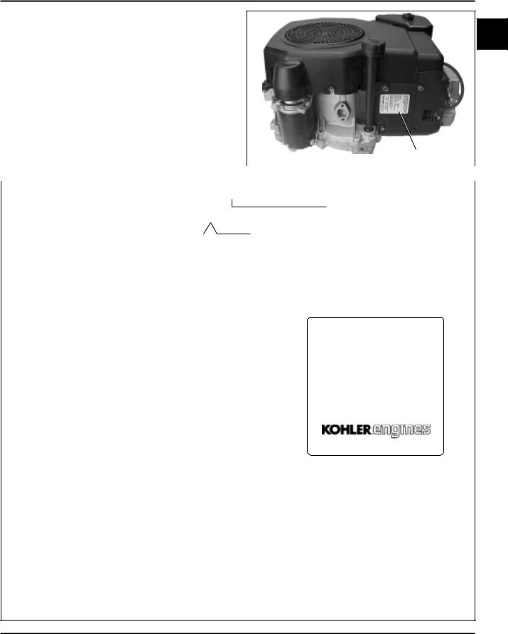
Engine Identification Numbers
When ordering parts, or in any communication
involving an engine, always give the Model, 1
Specification, and Serial Numbers of the engine.
The engine identification numbers appear a on decal (or decals) affixed to the engine shrouding. See Figure 1-1. An explanation of these numbers is shown in Figure 1-2.
|
|
|
|
|
|
|
|
|
|
|
|
|
|
|
|
|
|
|
|
|
|
|
|
|
|
|
|
|
|
|
|
|
|
|
|
Identification Decal |
||||
|
|
|
|
|
|
|
|
|
|
|
|
|
|
|
|
|
|
|
|
|
|
|
|
|
|
|
|
|
|
|
|
|
|
|
||||||
|
|
|
|
|
|
|
|
|
|
|
|
|
|
|
|
|
|
|
|
|
|
|
|
|
|
|
|
|
|
Figure 1-1. Engine Identification Decal Location. |
||||||||||
|
|
|
|
|
|
|
|
|
|
|
|
|
|
|
|
|
|
|
|
|
|
|
|
|
|
|
|
|
|
|
|
|
|
|
||||||
A. Model No. |
|
|
|
|
|
|
|
|
|
|
|
|
|
|
|
|
|
|
|
|
|
|
|
|
||||||||||||||||
|
|
C V 12.5 ST |
|
|
|
|
|
|
|
|
|
|
|
|||||||||||||||||||||||||||
Command Engine |
|
|
|
|
|
|
|
|
|
|
|
|
|
|
|
|
|
|
|
|
|
|
|
|
|
|
|
|
|
|
|
|
Version Code |
|
|
|||||
|
|
|
|
|
|
|
|
|
|
|
|
|
|
|
|
|
|
|
|
|
|
|
|
|
|
|
|
|
|
|
|
|
|
|||||||
Vertical Crankshaft |
|
|
|
|
|
|
|
|
|
|
|
|
|
|
|
|
|
|
|
|
|
|
|
|
|
|
|
|
|
|
|
S = Electric Start |
|
|
||||||
Displacement (cc) |
|
|
|
|
|
|
|
|
|
|
|
|
|
|
|
|
or |
|
|
|
|
|
|
|
|
|
Horsepower |
T = Retractable Start |
|
|
||||||||||
|
|
|
|
|
|
|
|
|
|
|
|
|
|
|
|
|
|
|
|
|
|
|
ST = Electric/Retractable Start |
|||||||||||||||||
460 = 460 cc |
|
|
|
|
|
|
|
|
|
|
|
|
|
|
|
|
|
|
|
|
|
|
|
11 = 11 HP |
|
|||||||||||||||
|
|
|
|
|
|
|
|
|
|
|
|
|
|
|
|
|
|
|
|
|
|
|
|
|
|
|
|
|
|
|||||||||||
490 = 490 cc |
|
|
|
|
|
|
|
|
|
|
|
|
|
|
|
|
|
|
|
|
|
|
|
12.5 = 12.5 HP |
|
|
|
|
|
|
||||||||||
|
|
|
|
|
|
|
|
|
|
|
|
|
|
|
|
|
|
|
|
|
|
|
|
|
|
|
|
|
|
|
13 = 13 HP |
|
|
|
|
|
|
|
||
|
|
|
|
|
|
|
|
|
|
|
|
|
|
|
|
|
|
|
|
|
|
|
|
|
|
|
|
|
|
|
14 = 14 HP |
|
|
|
|
|
|
|
||
|
|
|
|
|
|
|
|
|
|
|
|
|
|
|
|
|
|
|
|
|
|
|
|
|
|
|
|
|
|
|
15 = 15 HP |
|
|
|
|
|
|
|
||
|
|
|
|
|
|
|
|
|
|
|
|
|
|
|
|
|
|
|
|
|
|
|
|
|
|
|
|
|
|
|
16 = 16 HP |
|
|
|
|
|
|
|
||
B. Spec. No. |
1203 |
|
|
|
|
|
|
|
|
|
|
|
|
|
|
|
MODEL NO.CV12.5ST |
|
|
|
A |
|||||||||||||||||||
Engine Model Code |
|
|
|
|
|
|
|
|
|
|
|
|
|
|
|
|
|
Variation of |
|
|
|
|||||||||||||||||||
|
|
|
|
|
|
|
|
|
|
|
|
|
|
|
|
|
|
|
||||||||||||||||||||||
|
|
|
|
|
|
|
|
|
|
|
|
|
|
|
|
SPEC. NO. 1203 |
|
|
|
|
B |
|||||||||||||||||||
Code |
Model |
|
|
|
|
|
|
|
|
|
|
|
|
|
|
Basic Engine |
|
|
|
|||||||||||||||||||||
|
|
|
|
|
|
|
|
|
|
|
|
|
|
|
|
|||||||||||||||||||||||||
|
|
|
|
|
|
|
|
|
|
|
|
|
|
SERIAL NO.2105810334 |
|
|
C |
|||||||||||||||||||||||
11 |
CV11 |
|
|
|
|
|
|
|
|
|
|
|
|
|
|
|
|
|
|
|
|
|
|
|
|
|
|
|
|
|||||||||||
|
|
|
|
|
|
|
|
|
|
|
|
|
|
|
|
|
|
|
|
|
|
|
|
|
|
REFER TO OWNER'S MANUAL FOR |
|
|
||||||||||||
12 |
CV12.5 |
|
|
|
|
|
|
|
|
|
|
|
|
|
|
|
|
|
|
|
|
|
|
|
|
|
|
|
|
|||||||||||
22 |
CV13 |
|
|
|
|
|
|
|
|
|
|
|
|
|
|
|
|
|
|
|
|
|
|
|
|
|
|
SAFETY, MAINTENANCE SPECS |
|
|
||||||||||
|
|
|
|
|
|
|
|
|
|
|
|
|
|
|
|
|
|
|
|
|
|
|
|
|
|
AND ADJUSTMENTS. FOR SALES |
|
|
||||||||||||
14 |
CV14 |
|
|
|
|
|
|
|
|
|
|
|
|
|
|
|
|
|
|
|
|
|
|
|
|
|
|
|
|
|||||||||||
|
|
|
|
|
|
|
|
|
|
|
|
|
|
|
|
|
|
|
|
|
|
|
|
|
|
AND SERVICE IN US/CANADA |
|
|
||||||||||||
41 |
CV15 |
|
|
|
|
|
|
|
|
|
|
|
|
|
|
|
|
|
|
|
|
|
|
|
|
|
|
CALL: 1-800-544-2444. |
|
|
||||||||||
43 |
CV16 |
|
|
|
|
|
|
|
|
|
|
|
|
|
|
|
|
|
|
|
|
|
|
|
|
|
|
|
www.kohlerengines.com |
|
|
|||||||||
265 |
CV460-465 |
|
|
|
|
|
|
|
|
|
|
|
|
|
|
|
|
|
|
|
|
|
|
|
|
|
|
|
|
|
|
|
|
|
||||||
275 |
CV490-495 |
|
|
|
|
|
|
|
|
|
|
|
|
|
|
|
|
|
|
|
|
|
|
|
|
|
|
|
|
|
|
|
|
|
||||||
|
|
|
|
|
|
|
|
|
|
|
|
|
|
|
|
|
|
|
|
|
|
|
|
|
|
|
|
|
|
|
|
|
|
|
KOHLER CO. KOHLER, WI USA |
|
|
|||
C. Serial No. |
|
|
|
2105810334 |
|
|
|
|
|
|
||||||||||||||||||||||||||||||
|
|
|
|
|
|
|
|
|
|
|
||||||||||||||||||||||||||||||
Year Manufactured Code |
|
|
|
|
|
|
|
|
|
|
|
|
|
|
|
|
|
|
|
|
|
|
|
|
|
|
|
Factory Code |
|
|
||||||||||
|
|
|
|
|
|
|
|
|
|
|
|
|
|
|
|
|
|
|
|
|
|
|
|
|
|
|
|
|||||||||||||
|
|
|
|
|
|
|
|
|
|
|
|
|
|
|
|
|
|
|
|
|
|
|
|
|
|
|
|
|||||||||||||
Code |
Model |
|
|
|
|
|
|
|
|
|
|
|
|
|
|
|
|
|
|
|
|
|
|
|
|
|
|
|
|
|
|
|
|
|
||||||
211991
221992
231993
241994
251995
261996
271997
281998
291999
302000
312001
322002
Figure 1-2. Explanation of Engine Identification Numbers.
1.3
Section 1
Safety and General Information
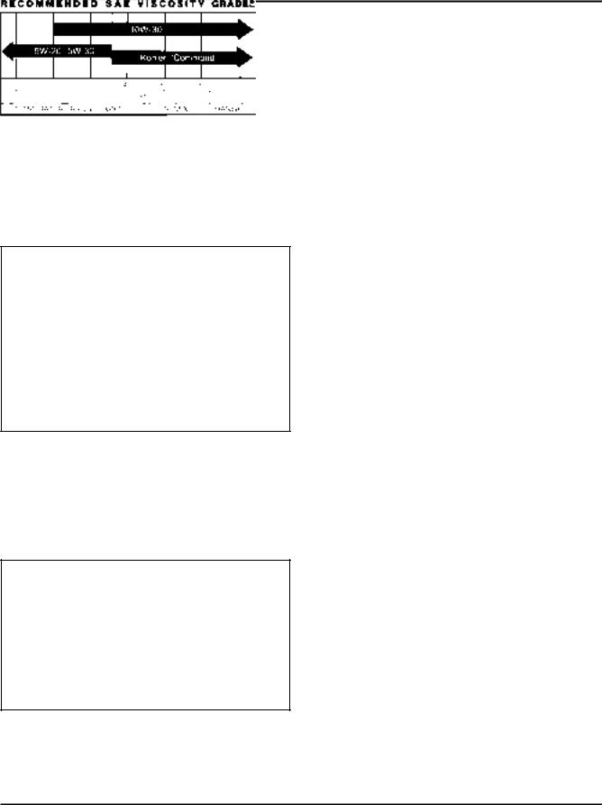
Oil Recommendations
Using the proper type and weight of oil in the crankcase is extremely important, as is checking oil daily, and changing oil regularly. Failure to use the correct oil, or using dirty oil, causes premature engine wear and failure. Synthetic oil is recommended for use in LPG-fueled engines because there is less oxidation or thickening, and deposit accumulation on intake valves is substantially reduced.
Oil Type
Use high-quality detergent oil of API (American
Petroleum Institute) service class SG, SH, SJ or higher. Select the viscosity based on the air temperature at the time of operation as shown below.
**
*
*Use of synthetic oil having 5W-20 or 5W-30 rating is acceptable, up to 4°C (40°F).
**Synthetic oils will provide better starting in extreme cold below -23°C (-10°F).
NOTE: Using other than service class SG, SH, SJ or higher oil, or extending oil change intervals longer than recommended, can cause engine damage.
A logo or symbol on oil containers identifies the API service class and SAE viscosity grade. See Figure 1-3.
Figure 1-3. Oil Container Logo.
Refer to Section 6 - “Lubrication System” for detailed oil check, oil change, and oil filter change procedures.
Fuel Recommendations
 WARNING: Explosive Fuel!
Gasoline is extremely flammable and its vapors can explode if ignited. Store gasoline only in approved containers, in well ventilated, unoccupied buildings, away from sparks or flames. Do not fill the fuel tank while the engine is hot or running, since spilled fuel could ignite if it comes in contact with hot parts or sparks from ignition. Do not start the engine near spilled fuel. Never use gasoline as a cleaning agent.
General Recommendations
Purchase gasoline in small quantities and store in clean, approved containers. A container with a capacity of 2 gallons or less with a pouring spout is recommended. Such a container is easier to handle and helps eliminate spillage during refueling.
Do not use gasoline left over from the previous season, to minimize gum deposits in your fuel system and to insure easy starting.
Do not add oil to the gasoline.
Do not overfill the fuel tank. Leave room for the fuel to expand.
Fuel Type
For best results, use only clean, fresh, unleaded gasoline with a pump sticker octane rating of 87 or higher. In countries using the Research method, it should be 90 octane minimum.
Unleaded gasoline is recommended, as it leaves less combustion chamber deposits. Leaded gasoline may be used in areas where unleaded is not available and exhaust emissions are not regulated. Be aware however, that the cylinder head will require more frequent service.
Gasoline/Alcohol blends
Gasohol (up to 10% ethyl alcohol, 90% unleaded gasoline by volume) is approved as a fuel for Kohler engines. Other gasoline/alcohol blends are not approved.
Gasoline/Ether blends
Methyl Tertiary Butyl Ether (MTBE) and unleaded gasoline blends (up to maximum of 15% MTBE by volume) are approved as a fuel for Kohler engines. Other gasoline/ether blends are not approved.
1.4

Section 1 |
|
||
Safety and General Information |
|
||
|
|
|
|
Periodic Maintenance |
|
||
1 |
|||
WARNING: Accidental Starts! |
|||
Disabling engine. Accidental starting can cause severe injury or death. Before working on the engine or |
|
||
|
|||
equipment, disable the engine as follows: 1) Disconnect the spark plug lead(s). 2) Disconnect negative (-) |
|
||
battery cable from battery. |
|
||
Maintenance Schedule
These required maintenance procedures should be performed at the frequency stated in the table. They should also be included as part of any seasonal tune-up.
Frequency |
|
Maintenance Required |
Refer to: |
|
|
|
|
|
|
Daily or Before |
• |
Fill fuel tank. |
Section 5 |
|
• |
Check oil level. |
Section 6 |
||
Starting Engine |
• |
Check air cleaner for dirty1, loose, or damaged parts. |
Section 4 |
|
|
• Check air intake and cooling areas, clean as necessary1. |
Section 4 |
||
Every 25 Hours |
• Service precleaner element1. |
Section 4 |
||
Every |
• Replace air cleaner element1. |
Section 4 |
||
• Change oil1. |
Section 6 |
|||
100 Hours |
||||
• Remove cooling shrouds and clean cooling areas1. |
Section 4 |
|||
|
||||
Every |
• |
Change oil filter1. |
Section 6 |
|
200 Hours |
• Check spark plug condition and gap. |
Section 8 |
||
|
|
|
|
|
Annually or |
• |
Have bendix starter drive serviced2. |
Section 8 |
|
Every |
• Have solenoid shift starter disassembled and cleaned2. |
Section 8 |
||
500 Hours |
|
|
|
|
1Perform these maintenance procedures more frequently under extremely dusty, dirty conditions. 2Have a Kohler Engine Service Dealer perform this service. Not necessary on Delco Starters.
Storage
If the engine will be out of service for two months or more, use the following storage procedure.
1.Clean the exterior surfaces of the engine.
2.Change the oil and oil filter while the engine is still warm from operation. See “Change Oil and Oil Filter” in Section 6.
3.The fuel system must be completely emptied, or the gasoline must be treated with a stabilizer to prevent deterioration. If you choose to use a stabilizer, follow the manufacturers recommendations, and add the correct amount for the capacity of the fuel system. Fill the fuel tank with clean, fresh gasoline. Run the engine for 2-3 minutes to get stabilized fuel into the carburetor.
To empty the system, run the engine until the tank and system are empty.
4.Remove the spark plug. Add one tablespoon of engine oil into the spark plug hole. Install the plug, but do not connect the plug lead. Crank the engine two or three revolutions.
5.Remove the spark plug. Cover the spark plug hole with your thumb, and turn the engine over until the piston is at the top of its stroke. (Pressure against thumb is greatest.) Reinstall the plug, but do not connect the plug lead.
6.Store the engine in a clean, dry place.
1.5

Section 1
Safety and General Information
Air Filter
and Cover
C Cylinder |
|
|
|
L |
|
|
|
|
|
Oil Filter |
|
Carburetor |
|
|
|
Fuel Shut-off |
|
|
|
Solenoid |
|
|
|
Carburetor |
|
47 |
|
Fuel Inlet |
|
(1.85) |
|
|
Engine Mounting |
|
|
|
|
|
|
Oil Drain Plug |
|
Surface |
|
17 |
|
|
|
3/8 NPT Inch |
|
|
|
(.67) |
262 |
|
|
|
|
||
|
|
(10.31) |
C Cylinder |
|
|
|
L |
Oil Filter Side
|
|
|
|
411 |
|
|
|
|
|
(16.18) |
|
|
|
|
|
Air Cleaner |
|
|
|
|
|
Cover Removal |
|
296 |
|
|
|
|
|
(11.65) |
|
|
|
|
|
321 |
C Cylinder |
|
|
|
|
L |
|
|
|
||
(12.64) |
|
|
|
|
|
|
137.5 |
|
|
|
|
|
(5.41) |
|
|
|
|
|
|
Exhaust Flange |
62.5 |
||
Engine Mounting |
(2.46) |
||||
Mounting Surface |
|||||
Surface |
|
19 |
|||
|
|
|
|||
Starter Motor |
25.4 |
|
(.74) |
||
(1.00) |
|
|
|||
|
|
|
|
||
|
|
6.34 |
|
|
|
Starter Side |
(.250) Keyway Width |
|
|||
|
|
220.2 |
|
|
|
|
|
(8.67) |
|
|
|
|
45° |
45° |
|
|
|
|
|
|
|
60.0 |
|
4xM8x1.25 |
|
|
|
(2.36) |
|
|
|
|
|
||
254 |
|
|
|
4.0 |
|
(10.0) |
|
|
|
(.16) |
|
CL Cylinder |
|
|
|
||
|
Rotation |
|
40° |
|
|
|
|
|
|
||
|
|
|
M8x1.25 |
|
|
|
|
|
2 Studs |
|
|
|
35° |
35° |
Exhaust Flange |
||
|
|
|
Mounting Surface |
||
24.0
(9.4)
Valve Cover End |
25.4 |
(1.00) |
6.34 Keyway Width
(.250)
26.5 |
|
|
(1.04) |
|
C |
|
|
|
|
|
L Throttle Cable |
|
|
207 |
204 |
|
(80.16) |
|
|
|
(8.04) |
|
176.6 |
372 |
|
(6.95) |
|
|
|
(14.66) |
|
|
|
|
C Cylinder |
124 |
|
L |
|
|
|
(4.88) |
|
|
|
|
Oil Level |
135.0 |
108 |
Dipstick & Fill |
|
||
(5.31) |
(4.25) |
|
328*
(12.91)
463*
(18.23)
Flywheel End
*CV11-16 10 mm shorter
Engine Mounting Surface
Dimensions in () are inch equivalents.
Figure 1-4. Typical Engine Dimensions.
1.6

Section 1
Safety and General Information
General Specifications¹ |
|
|
Power (@ 3600 RPM, corrected to SAE J1995) |
|
|
|
1 |
|
CV11 ............................................................................... |
8.2 kW (11 HP) |
|
CV12.5 ............................................................................ |
9.33 kW (12.5 HP) |
|
CV13 ............................................................................... |
9.75 kW (13 HP) |
|
CV14 ............................................................................... |
10.5 kW (14 HP) |
|
CV15 ............................................................................... |
11.19 kW (15 HP) |
|
CV16 ............................................................................... |
11.9 kW (16 HP) |
|
CV460-465 ...................................................................... |
11.9 kW (16 HP)-13.0 kW (16.5 HP) |
|
CV490-495 ...................................................................... |
12.7 kW (17 HP)-13.4 kW (18 HP) |
|
Max Torque (@ RPM indicated) |
|
CV11 ................................................................................ |
27.4 N·m (20.2 ft. lb.) @ 2000 |
CV12.5 ............................................................................. |
27.8 N·m(20.5 ft. lb.) @ 2500 |
CV13 ................................................................................ |
27.8 N·m(20.5 ft. lb.) @ 2500 |
CV14 ................................................................................ |
28.9 N·m(21.3 ft. lb.) @ 2500 |
CV15 ................................................................................ |
33.2 N·m(24.5 ft. lb.) @ 2400 |
CV16 ................................................................................ |
35.3 N·m(26.0 ft. lb.) @ 2400 |
CV460-465 ....................................................................... |
36.3 N·m(26.8 ft. lb.) @ 2400 |
CV490-495 ....................................................................... |
37.8 N·m (27.9 ft. lb.)-38.1 N·m (28.1 ft. lb.)@ 2400 |
Bore |
|
CV11-14, CV460-465 ........................................................ |
87 mm (3.43 in.) |
CV15, CV16, CV490-495 .................................................. |
90 mm (3.60 in.) |
Stroke |
|
CV11-16 .......................................................................... |
67 mm (2.64 in.) |
CV460-465, CV490-495 .................................................. |
77 mm (3.03 in.) |
Displacement |
|
CV11-14 ............................................................................ |
398 cc (24.3 cu. in.3) |
CV15, CV16 ...................................................................... |
426 cc (26.0 cu. in.3) |
CV460-465 ........................................................................ |
460 cc (27.9 cu. in.3) |
CV490-495 ........................................................................ |
490 cc (29.9 cu. in.3) |
Compression Ratio .................................................................. |
8.5:1 |
Weight (approx.) |
|
CV11-16 ............................................................................ |
39.54 kg (87 lb.) |
CV460-465, CV490-495 .................................................... |
41.9 kg (90 lb.) |
Oil Capacity (approx.) .............................................................. |
1.9 L (2.0 U.S. qt.) |
Air Cleaner |
|
Base Nut Torque ...................................................................... |
9.9 N·m(88 in. lb.) |
Wing Nut Torque ...................................................................... |
1.5 N·m(12 in. lb.) |
Angle of Operation - Maximum (at full oil level) |
|
Intermittent - All Directions ....................................................... |
35° |
Continuous - All Directions ....................................................... |
20° |
1Values are in Metric units. Values in parentheses are English equivalents. Lubricate threads with engine oil prior to assembly.
1.7

Section 1
Safety and General Information
Balance Shaft |
|
End Play ...................................................................................................... |
0.0575/0.3625 mm (0.0027/0.0137 in.) |
Running Clearance ...................................................................................... |
0.0250/0.1520 mm (0.0009/0.0059 in.) |
Bore I.D. |
|
New ....................................................................................................... |
20.000/20.025 mm (0.7874/0.7884 in.) |
Max. Wear Limit .................................................................................... |
20.038 mm (0.7889 in.) |
Balance Shaft Bearing Surface O.D. |
|
New ....................................................................................................... |
19.962/19.975 mm (0.7859/0.7864 in.) |
Max. Wear Limit .................................................................................... |
19.959 mm (0.7858 in.) |
Camshaft |
|
End Play (free) ............................................................................................. |
0.088/0.393 mm (0.003/0.015 in.) |
End Play (with shims) .................................................................................. |
0.076/0.127 mm (0.003/0.005 in.) |
Running Clearance ...................................................................................... |
0.025/0.105 mm (0.0010/0.0041 in.) |
Bore I.D. |
|
New ....................................................................................................... |
20.000/20.025 mm (0.7874/0.7884 in.) |
Max. Wear Limit .................................................................................... |
20.038 mm (0.7889 in.) |
Camshaft Bearing Surface O.D. |
|
New ...................................................................................................... |
19.962/19.975 mm (0.7859/0.7864 in.) |
Max. Wear Limit ................................................................................... |
19.959 mm (0.7858 in.) |
Carburetor |
|
Preliminary Low Idle Fuel Needle Setting ................................................... |
1 Turn |
Fuel Bowl Retaining Screw Torque ............................................................. |
5.1-6.2 N·m(45-55 in. lb.) |
Connecting Rod |
|
Cap Fastener Torque (torque in increments) |
|
6 mm straight shank bolt ....................................................................... |
11.3 N·m (100 in. lb.) |
8 mm step-down bolt ............................................................................. |
14.7 N·m(130 in. lb.) |
8 mm straight shank bolt ....................................................................... |
22.7 N·m (200 in. lb.) |
Connecting Rod-to-Crankpin Running Clearance at 21°C (70°F) |
|
New ....................................................................................................... |
0.030/0.055 mm (0.0012/0.0022 in.) |
Max. Wear Limit .................................................................................... |
0.07 mm (0.0025 in.) |
Connecting Rod-to-Crankpin Side Clearance .............................................. |
0.18/0.41 mm (0.007/0.016 in.) |
Connecting Rod-to-Piston Pin Running Clearance at 21°C (70°F) .............. |
0.015/0.028 mm (0.0006/0.0011 in.) |
Piston Pin End I.D. |
|
New ...................................................................................................... |
19.015/19.023 mm (0.7486/0.7489 in.) |
Max. Wear Limit ................................................................................... |
19.036 mm (0.7495 in.) |
Crankcase |
|
Governor Cross Shaft Bore I.D. |
|
New ...................................................................................................... |
6.025/6.050 mm (0.2372/0.2382 in.) |
Max. Wear Limit ................................................................................... |
6.063 mm (0.2387 in.) |
1.8
|
Section 1 |
|
|
Safety and General Information |
|
Crankshaft |
|
|
End Play (free) ........................................................................................ |
0.0575/0.4925 mm (0.0022/0.0193 in.) |
|
End Play (thrust bearing with shims) ...................................................... |
0.050/0.530 mm (0.0020/0.0209 in.) |
1 |
Crankshaft Bore in Crankcase I.D. |
|
|
New .................................................................................................. |
44.965/44.990 mm (1.7702/1.7712 in.) |
|
Max. Wear Limit ............................................................................... |
44.9758/45.0012 mm (1.7707/1.7717 in.) |
|
Crankshaft Bore in Crankcase Running Clearance |
|
|
New .................................................................................................. |
0.0300/0.0770 mm (0.0011/0.0030 in.) |
|
Crankshaft Bore in Oil Pan I.D. |
|
|
New .................................................................................................. |
41.965/42.003 mm (1.6521/1.6536 in.) |
|
Max. Wear Limit ............................................................................... |
41.9760/42.0141 mm (1.6526/1.6541 in.) |
|
Crankshaft Bore in Oil Pan Running Clearance |
|
|
New .................................................................................................. |
0.0300/0.0880 mm (0.0011/0.0034 in.) |
|
Flywheel End Main Bearing Journal |
|
|
O.D. - New ....................................................................................... |
44.913/44.935 mm (1.7682/1.7691 in.) |
|
O.D. - Max. Wear Limit .................................................................... |
44.84 mm (1.765 in.) |
|
Max. Taper ....................................................................................... |
0.022 mm (0.0009 in.) |
|
Max. Out-of-Round .......................................................................... |
0.025 mm (0.0010 in.) |
|
Oil Pan End Main Bearing Journal |
|
|
O.D. - New ....................................................................................... |
41.915/41.935 mm (1.6502/1.6510 in.) |
|
O.D. - Max. Wear Limit .................................................................... |
41.86 mm (1.648 in.) |
|
Max. Taper ....................................................................................... |
0.020 mm (0.0008 in.) |
|
Max. Out-of-Round .......................................................................... |
0.025 mm (0.0010 in.) |
|
Connecting Rod Journal |
|
|
O.D. - New ....................................................................................... |
38.958/30.970 mm (1.5338/1.5343 in.) |
|
O.D. - Max. Wear Limit .................................................................... |
38.94 mm (1.5328 in.) |
|
Max. Taper ....................................................................................... |
0.012 mm (0.0005 in.) |
|
Max. Out-of-Round .......................................................................... |
0.025 mm (0.0010 in.) |
|
Crankshaft T.I.R. |
|
|
PTO End, Crank in Engine ............................................................... |
0.30 mm (0.012 in.) |
|
Entire Crank, in V-Blocks ................................................................. |
0.10 mm (0.0039 in.) |
|
Cylinder Bore |
|
|
Cylinder Bore I.D. |
|
|
New |
|
|
CV11-14, CV460-465 ..................................................................... |
87.000/87.025 mm (3.4252/3.4262 in.) |
|
CV15, CV16, CV490-495 ............................................................... |
90.000/90.025 mm (3.5433/3.5443 in.) |
|
Max. Wear Limit |
|
|
CV11-14, CV460-465 ..................................................................... |
87.063 mm (3.4277 in.) |
|
CV15, CV16, CV490-495 ............................................................... |
90.063 mm (3.5458 in.) |
|
Max. Out-of-Round .......................................................................... |
0.12 mm (0.0047 in.) |
|
Max. Taper ....................................................................................... |
0.05 mm (0.0020 in.) |
|
1.9

Section 1
Safety and General Information
Cylinder Head |
|
Cylinder Head Fastener Torque (torque in 2 increments)......... |
20, 40.7 N·m (15, 30 ft. lb.) |
Max. Out-of-Flatness ............................................................... |
0.076 mm (0.003 in.) |
Rocker Pedestal Fastener Torque ........................................... |
11.3 N·m (100 in. lb.) |
Electric Starter |
|
Starter Thru Bolt Torque |
|
UTE/Johnson Electric, Eaton (Inertia Drive) ...................... |
4.5-5.7 N·m (40-50 in. lb.) |
Nippendenso (Solenoid Shift) ............................................ |
4.5-7.5 N·m(40-84 in. lb.) |
Delco-Remy (Solenoid Shift) ............................................. |
5.6-9.0 N·m(49-79 in. lb.) |
Starter Mounting Screw Torque (All) ........................................ |
15.3 N·m (135 in. lb.) |
Solenoid Mounting Hardware (Nut/Screw) Torque |
|
Nippendenso Starter ......................................................... |
6.0-9.0 N·m(53-79 in. lb.) |
Delco-Remy Starter ........................................................... |
4.0-6.0 N·m(35-53 in. lb.) |
Brush Holder Mounting Screw Torque |
|
Delco-Remy Starter ........................................................... |
2.5-3.3 N·m(22-29 in. lb.) |
Nut, Positive (+) Brush Lead Torque |
|
Nippendenso Starter ................................................... |
8.0-12.0 N·m(71-106 in. lb.) |
Delco-Remy Starter .................................................... |
6.0-9.0 N·m(53-79 in. lb.) |
Fan/Flywheel |
|
Fan Fastener Torque ............................................................... |
9.9 N·m(88 in. lb.) |
Flywheel Retaining Screw Torque ............................................ |
66.4 N·m (49 ft. lb.) |
Fuel Pump |
|
Fuel Pump Fastener Torque .................................................... |
9.0 N·m (80in. lb.) Into new as-cast hole |
|
4.2-5.1 N·m (37-45 in. lb.) Into used hole |
Fuel Pump Pad Cover Fastener Torque .................................. |
10.7 N·m (95 in. lb.) Into new as-cast hole |
|
7.3 N·m (65 in. lb.) Into used hole |
Governor |
|
Governor Cross Shaft to Crankcase Running Clearance......... |
0.025/0.075 mm (0.0010/0.0030 in.) |
Governor Cross Shaft O.D. |
|
New ................................................................................... |
5.975/6.000 mm (0.2352/0.2362 in.) |
Max. Wear Limit ................................................................ |
5.962 mm (0.2347 in.) |
Governor Gear Shaft-to-Governor Gear Running Clearance ... 0.050/0.160 mm (0.0019/0.0063 in.)
Governor Gear Shaft O.D. |
|
New ................................................................................... |
5.990/6.000 mm (0.2358/0.2362 in.) |
Max. Wear Limit ................................................................ |
5.977 mm (0.2353 in.) |
Ignition |
|
Spark Plug Type (Champion® or equivalent) ............................. |
RC12YC (Standard) or |
|
Premium Gold 2071 (Pro Series) |
Spark Plug Gap |
|
CV11-15, CV460-465, CV490-495 .................................... |
1.02 mm (0.040 in.) |
CV11-14 LP, CV16 ............................................................ |
0.76 mm (0.030 in.) |
1.10

|
Section 1 |
|||
|
Safety and General Information |
|||
|
|
|
|
|
Ignition (Cont'd) |
|
|
|
|
...................................................................Spark Plug Torque |
24.4-29.8 N·m (18-22 ft. lb.) |
1 |
||
Ignition Module Air Gap ........................................................... |
0.200/0.300 mm (0.0078/0.0118 in.) |
|||
|
||||
|
||||
Ignition Module Fastener Torque ............................................. |
6.2 N·m (55 in.lb.) Into new as-cast hole |
|||
|
4.0 N·m (35 in. lb.) Into used hole |
|||
Muffler |
|
|
|
|
Muffler Retaining Nuts ............................................................. |
24.4 N·m(216 in. lb.) |
|||
Oil Filter/Oil Pan |
|
|
|
|
Oil Filter Torque ....................................................................... |
10.4-12.7 N·m (90-110 in. lb.) |
|||
Oil Filter Drain Plug (1/8" NPT) Torque .................................... |
7.3-9.0 N·m(65-80 in. lb.) |
|||
Oil Pan Fastener Torque .......................................................... |
24.4 N·m(216 in. lb.) |
|||
Oil Sentry™ Pressure Switch Torque ........................................ |
6.8 N·m (60 in. lb.) |
|||
Oil Pump Cover Fastener Torque ............................................ |
6.2 N·m(55 in. lb.) Into new as-cast hole |
|||
|
4.0 N·m (35 in. lb.) Into used hole |
|||
Piston, Piston Rings, and Piston Pin |
|
|
|
|
Piston-to-Piston Pin (selective fit) ............................................ |
0.006/0.017 mm (0.0002/0.0007 in.) |
|||
Piston Pin Bore I.D. |
|
|
|
|
New ................................................................................... |
19.006/19.012 mm (0.7483/0.7485 in.) |
|||
Max. Wear Limit ................................................................ |
19.025 mm (0.7490 in.) |
|||
Piston Pin O.D. |
|
|
|
|
New ................................................................................... |
18.995/19.000 mm (0.7478/0.7480 in.) |
|||
Max. Wear Limit ................................................................ |
18.994 mm (0.74779 in.) |
|||
Top Compression Ring-to-Groove Side Clearance |
|
|
|
|
CV11-14, CV460-465 ........................................................ |
0.034/0.100 mm (0.0013/0.0039 in.) |
|||
CV15, CV16, CV490-495 .................................................. |
0.060/0.105 mm (0.0023/0.0041 in.) |
|||
Middle Compression Ring-to-Groove Side Clearance |
|
|
|
|
CV11-14, CV460-465 ........................................................ |
0.040/0.080 mm (0.0016/0.0032 in.) |
|||
CV15, CV16, CV490-495 .................................................. |
0.040/0.085 mm (0.0015/0.0033 in.) |
|||
Oil Control Ring-to-Groove Side Clearance |
|
|
|
|
CV11-14, CV460-465 ........................................................ |
0.036/0.186 mm (0.0014/0.0073 in.) |
|||
CV15, CV16, CV490-495 .................................................. |
0.036/0.186 mm (0.0014/0.0073 in.) |
|||
Top Compression Ring End Gap |
|
|
|
|
New Bore |
|
|
|
|
CV11-14, CV460-465 ...................................................... |
0.250/0.500 mm (0.010/0.020 in.) |
|||
CV15, CV16, CV490-495 ................................................ |
0.28/0.51 mm (0.011/0.020 in.) |
|||
Used Bore (max.) .............................................................. |
0.79 mm (0.031 in.) |
|||
1.11

Section 1
Safety and General Information
Piston, Piston Rings, and Piston Pin (Cont'd.) |
|
Center Compression Ring End Gap |
|
New Bore |
|
CV11-14, CV460-465 ...................................................... |
0.250/0.510 mm (0.0010/0.020 in.) |
CV15, CV16, CV490-495 ................................................ |
0.22/0.48 mm (0.008/0.018 in.) |
Used Bore (max.) .............................................................. |
0.76 mm (0.030 in.) |
Oil Control Ring End Gap |
|
CV11-14, CV460-465 ........................................................ |
0.250/1.020 mm (0.010/0.040 in.) |
CV15, CV16, CV490-495 .................................................. |
0.250/0.760 mm (0.0098/0.0299 in.) |
Piston Thrust Face O.D. (See Figure 10-4) |
|
New |
|
CV11-14, CV460-465 ...................................................... |
86.941/86.959 mm (3.4229/3.4236 in.) |
CV15, CV16, CV490-495 ................................................ |
89.951/89.969 mm (3.5413/3.5420 in.) |
Max. Wear Limit |
|
CV11-14, CV460-465 ...................................................... |
86.814 mm (3.4179 in.) |
CV15, CV16, CV490-495 ................................................ |
89.824 mm (3.5363 in.) |
Piston Thrust Face (See Figure 10-4)-to-Cylinder Bore Running Clearance - New |
|
CV11-14, CV460-465 ........................................................ |
0.041/0.044 mm (0.0016/0.0017 in.) |
CV15, CV16, CV490-495 .................................................. |
0.031/0.043 mm (0.0012/0.0016 in.) |
Retractable Starter |
|
Center Screw Torque ............................................................... |
7.4-8.5 N·m(65-75 in. lb.) |
Stator |
|
Stator Mounting Screw Torque ................................................. |
6.2 N·m (55 in. lb.) |
Throttle/Choke Controls |
|
Governor Control Lever Fastener Torque ................................ |
9.9 N·m (88 in. lb.) |
Speed Control Bracket Assembly Fastener Torque .................. |
10.7 N·m (95in. lb.) Into new as-cast hole |
|
7.3 N·m (65 in. lb.) Into used hole |
Valve Cover/Rocker Arms |
|
Valve Cover Fastener Torque .................................................. |
10.7 N·m (95 in. lb.) Into new as-cast hole |
|
7.3 N·m (65 in. lb.) Into used hole |
Rocker Arm I.D. |
|
New ................................................................................... |
15.837/16.127 mm (0.63/0.64 in.) |
Max. Wear Limit ................................................................ |
16.13 mm (0.640 in.) |
Rocker Shaft O.D. |
|
New ................................................................................... |
15.90/15.85 mm (0.63 in.) |
Max. Wear Limit ................................................................ |
15.727 mm (0.619 in.) |
Non-Adjustable Valve Lash Configuration |
|
Rocker Arm Screw Torque ................................................ |
11.3 N·m (100 in. lb.) |
Adjustable Valve Lash Configuration |
|
Rocker Arm Pivot Stud Torque .......................................... |
11.3 N·m (100 in. lb.) |
Adjustment Set Screw Torque ........................................... |
7.3 N·m (65 in. lb.) |
1.12

|
Section 1 |
|
||
|
Safety and General Information |
|
||
|
|
|
|
|
Valves and Valve Lifters |
|
|
|
|
..........Hydraulic Valve Lifter to Crankcase Running Clearance |
0.0124/0.0501 mm (0.0005/0.0020 in.) |
1 |
||
Intake Valve Stem-to-Valve Guide Running Clearance ............ |
0.038/0.076 mm (0.0015/0.0030 in.) |
|||
|
||||
|
||||
Exhaust Valve Stem-to-Valve Guide Running Clearance ......... |
0.050/0.088 mm (0.0020/0.0035 in.) |
|
||
Intake Valve Guide I.D. |
|
|
|
|
New ................................................................................... |
7.038/7.058 mm (0.2771/0.2779 in.) |
|
||
Max. Wear Limit ................................................................ |
7.134 mm (0.2809 in.) |
|
||
Exhaust Valve Guide I.D. |
|
|
|
|
New ................................................................................... |
7.038/7.058 mm (0.2771/0.2779 in.) |
|
||
Max. Wear Limit ................................................................ |
7.159 mm (0.2819 in.) |
|
||
Valve Guide Reamer Size |
|
|
|
|
STD ................................................................................... |
7.048 mm (0.2775 in.) |
|
||
0.25 mm O.S. .................................................................... |
7.298 mm (0.2873 in.) |
|
||
Intake Valve Minimum Lift ........................................................ |
8.96 mm (0.353 in.) |
|
||
Exhaust Valve Minimum Lift ..................................................... |
9.14 mm (0.360 in.) |
|
||
Nominal Valve Seat Angle ........................................................ |
45° |
|
|
|
1.13

Section 1
Safety and General Information
General Torque Values
Metric Fastener Torque Recommendations for Standard Applications
Tightening Torque: N·m (in. lb.) + or - 10%
|
|
|
|
|
Property Class |
|
|
|
|
|
|
|
|
|
|
|
|
|
|
|
|
|
|
Noncritical |
|
|
|
|
|
|
|
|
|
|
|
|
Fasteners |
|
Size |
|
|
|
|
|
|
|
|
|
|
Into Aluminum |
|
|
|
|
|
|
|
|
|
|
|
|
|
|
M4 |
1.2 |
(11) |
1.7 |
(15) |
2.9 |
(26) |
4.1 |
(36) |
5.0 |
(44) |
2.0 |
(18) |
M5 |
2.5 |
(22) |
3.2 |
(28) |
5.8 |
(51) |
8.1 |
(72) |
9.7 |
(86) |
4.0 |
(35) |
M6 |
4.3 |
(38) |
5.7 |
(50) |
9.9 |
(88) |
14.0 |
(124) |
16.5 |
(146) |
6.8 |
(60) |
M8 |
10.5 |
(93) |
13.6 |
(120) |
24.4 |
(216) |
33.9 |
(300) |
40.7 |
(360) |
17.0 |
(150) |
|
|
|
|
|
|
|
||||||
Tightening Torque: N·m (ft. lb.) + or - 10% |
|
|
|
|
|
|
||||||
|
|
|
|
|
Property Class |
|
|
|
|
Noncritical |
||
|
|
|
|
|
|
|
|
|
|
|
||
|
|
|
|
|
|
|
|
|
|
|
Fasteners |
|
|
|
|
|
|
|
|
|
|
|
|
Into Aluminum |
|
M10 |
21.7 |
(16) |
27.1 |
(20) |
47.5 |
(35) |
66.4 |
(49) |
81.4 |
(60) |
33.9 |
(25) |
M12 |
36.6 |
(27) |
47.5 |
(35) |
82.7 |
(61) |
116.6 |
(86) |
139.7 |
(103) |
61.0 |
(45) |
M14 |
58.3 |
(43) |
76.4 |
(55) |
131.5 |
(97) |
184.4 |
(136) |
219.7 |
(162) |
94.9 |
(70) |
Oil Drain Plugs Tightening Torque: N•m (English Equiv.)
Size |
Into Cast Iron |
Into Aluminum |
1/8" NPT |
– |
4.5 (40 in. lb.) |
1/4" |
17.0 (150 in. lb.) |
11.3 (100 in. lb.) |
3/8" |
20.3 (180 in. lb.) |
13.6 (120 in. lb.) |
1/2" |
27.1 (20 ft. lb.) |
17.6 (13 ft. lb.) |
3/4" |
33.9 (25 ft. lb.) |
21.7 (16 ft. lb.) |
X-708-1 |
27.1/33.9 (20/25 ft. lb.) |
27.1/33.9 (20/25 ft. lb.) |
|
|
|
Torque
Conversions
N·m = in. lb. x 0.113 N·m = ft. lb. x 1.356 in. lb. = N·m x 8.85 ft. lb. = N·m x 0.737
1.14

SectionCV11-162
CV460-465,SpecialCV490Tools-495
Section 2 |
|
Special Tools |
2 |
Kohler Special Service Tools
Kohler Co. has made an agreement with the Service Tools Div. of SPX Corp. (a subsidiary of Owatonna Tool Corp.) to handle our special service tools. The intent of this program is to provide you with a single source for all Kohler special tools, and to make it easy and convenient to obtain those tools, at reasonable cost. Tool orders can be placed with SPX by any of three methods. Mail orders should be sent to: OTC/SPX Corp., 655 Eisenhower Dr., Owatonna, MN 55060. You can also fax the order to (800) 578-7375 (USA and Canada) or (507) 455-7063 (International). Finally, you can order by phone at (800) 533-0492 (USA and Canada) or (507) 455-7223 (International).
Repair Tools
These quality tools are designed to help you perform specific disassembly, repair, and reassembly procedures. By using tools designed for the job, you can service engines easier, faster, and safer! In addition, you’ll increase your service capabilities and customer satisfaction by decreasing engine down time.
Tool Kit No. KO3211A–This basic tool kit includes tools necessary to service Kohler K-Series and Magnum engines.
COMMAND Tool Kit No. KO3213–This kit is designed for the current Kohler Engine Service Dealer already having the KO3211A basic tool kit. This kit includes all additional tools necessary to service current Command series engines.
COMMAND Tool Kit No. KO3214–This kit is for the new Kohler Dealer servicing the Command series engines only.
RTV Silicone Sealant
RTV silicone sealant is used as a gasket between the crankcase and closure plate, and between the valve cover and head. The recommended sealant is Loctite® 5900, available under Kohler Part No. 25 597 07-S. Prepare the sealing surfaces of the crankcase and closure plate as directed by the sealant manufacturer or refer to Service Bulletin 252.
2.1

Section 2
Special Tools
Diagnostic and Repair Tools
The tools listed in the following table are used for specific diagnosis or repair procedures, as described. Order from SPX Corp.
Description |
SPX Part No. |
|
|
Hydraulic Lifter Tool |
|
Designed to remove and install hydraulic lifters |
KO1044 |
|
|
Ignition Tester |
|
Used for testing output on capacitive discharge (CD) ignition systems |
KO1046 |
|
|
Ignition Tester |
|
Used for testing ouput on all other systems, except CD |
KO1047 |
|
|
Water Manometer |
|
Used for testing crankcase vacuum and exhaust back pressure |
KO1048 |
|
|
Inductive Tachometer |
|
Used for checking the operating speed (RPM) of an engine |
KO3216 |
|
|
Ammeter Set |
|
Used for checking current flow in charging and cranking circuits |
KO3218 |
|
|
Cylinder Leakdown Tester |
|
Used for checking combustion retention and if cylinder, piston, rings, or valves are worn |
KO3219 |
|
|
Oil Pressure Test Kit |
|
Used to test/verify oil pressure on pressure lubricated engines |
KO3220 |
|
|
Electric Starter Service Kit |
|
Used to service all electric starters, including solenoid shift |
KO3226 |
|
|
Electric Starter Service Kit |
|
Used to remove and reinstall drive retainers on most inertia drive starters |
KO1049 |
|
|
Rectifier-Regulator Tester |
|
Used for testing rectifier-regulators |
KO3221 |
|
|
Spark Advance Module Tester |
|
Used to test the SAM on engines with Smart Spark |
KO3222 |
|
|
Vacuum/Pressure Tester |
|
Used like the water manometer but easier to operate, transport, and maintain |
KO3223 |
|
|
Spanner Wrench |
|
Used for installing push rods or rotating crankshaft |
OEM6200 |
|
|
Engine Analysis Kit |
|
Used for testing running conditions of Kohler engines in applications |
KO1000A |
|
|
2.2
Section 2
Special Tools
Special Tools You Can Make
Flywheel Holding Tool
Flywheel removal and reinstallation becomes a “snap” using a handy holding tool you can make out of a piece of an old “junk” flywheel ring gear as shown in Figure 2-1. Using an abrasive cut-off wheel, cut out a six tooth segment of the ring gear as shown. Grind off any burrs or sharp edges. The segment can be used in place of a strap wrench. Invert the segment and place it between the ignition module bosses on the crankcase, so the tool teeth engage the ring gear teeth on the flywheel. The bosses will “lock” the tool and flywheel in position for loosening, tightening or removing with a puller.
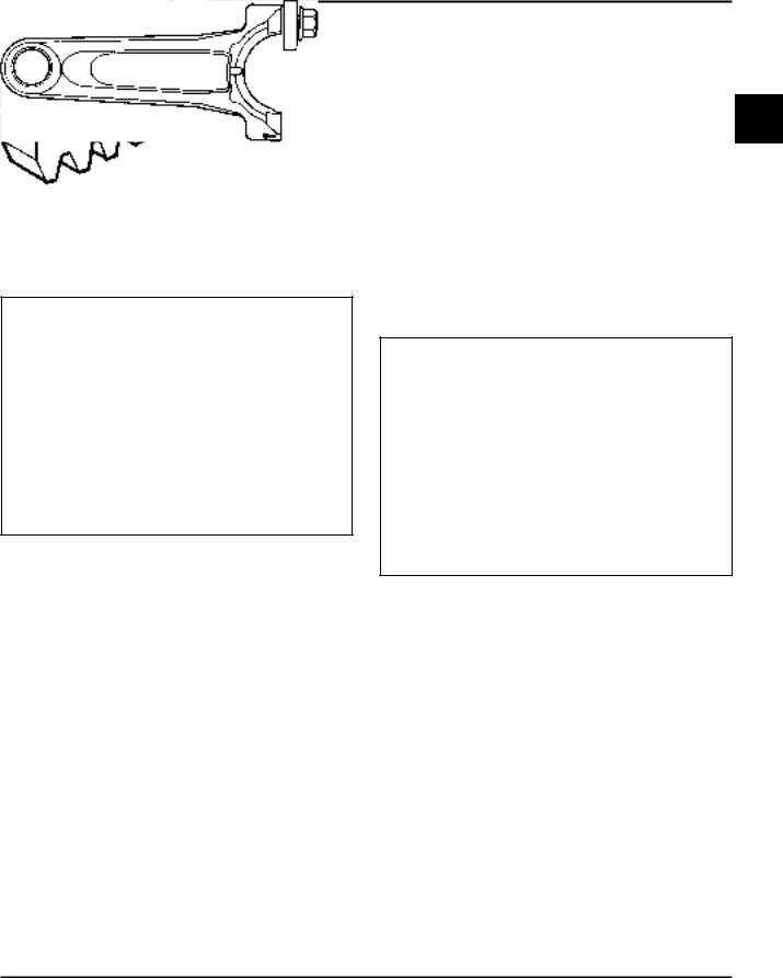
Rocker Arm/Crankshaft Tool
If you don’t have a spanner wrench to lift the rocker arms or to turn the crankshaft, you can make a tool for doing this out of an old junk connecting rod.
Find a used connecting rod from a 10 HP or larger
engine. Remove and discard the rod cap. If it is a 2 Posi-Lock rod, you will also need to remove the studs.
If it is a Command rod, you will need to grind off the aligning steps, so the joint surface is flat. Find a 1" long capscrew with the correct thread size to match the threads in the connecting rod. Obtain a flat washer with the correct I.D. to slip on the capscrew and an O.D. of approximately 1". Kohler Part No. 12 468 05-S can be used if you don’t have the right size on hand. Assemble the capscrew and washer to the joint surface of the rod, as shown in Figure 2-2.
Figure 2-1. Flywheel Holding Tool.
Figure 2-2. Rocker Arm/Crankshaft Tool.
2.3

Section 2
Special Tools
2.4
SectionCV11-163
CV460Troubleshooting-465, CV490-495
Section 3
Troubleshooting
3
Troubleshooting Guide |
Engine Will Not Crank |
When troubles occur, be sure to check the simple causes which, at first, may seem too obvious to be considered. For example, a starting problem could be caused by an empty fuel tank.
Some common causes of engine troubles are listed below. Use these to locate the causing factors.
Engine Cranks But Will Not Start
1.Empty fuel tank.
2.Fuel shut-off valve closed.
3.Dirt or water in the fuel system.
4.Clogged fuel line.
5.Spark plug lead disconnected.
6.Key switch or kill switch in ‘‘off’’ position.
7.Faulty spark plug.
8.Faulty ignition module.
Engine Starts But Does Not Keep Running
1.Restricted fuel tank cap vent.
2.Dirt or water in the fuel system.
3.Faulty choke or throttle controls.
4.Loose wires or connections that short the kill terminal of ignition module to ground.
5.Faulty carburetor.
6.Faulty cylinder head gasket.
Engine Starts Hard
1.PTO drive is engaged.
2.Dirt or water in the fuel system.
3.Clogged fuel line.
4.Loose or faulty wires or connections.
5.Faulty choke or throttle controls.
6.Faulty spark plug.
7.Low compression.
8.Faulty ACR mechanism.
1.PTO drive is engaged.
2.Battery (if equipped) is discharged.
3.Safety interlock switch is engaged.
4.Loose or faulty wires or connections.
5.Faulty key switch or ignition switch.
6.Faulty electric starter (if equipped).
7.Retractable starter not engaging in drive cup.
8.Seized internal engine components.
Engine Runs But Misses
1.Dirt or water in the fuel system.
2.Spark plug lead disconnected.
3.Loose wires or connections that intermittently short the kill terminal of ignition module to ground.
4.Engine overheated.
5.Faulty ignition module.
Engine Will Not Idle
1.Restricted fuel tank cap vent.
2.Dirt or water in the fuel system.
3.Faulty spark plug.
4.Idle fuel adjusting needle improperly set.
5.Idle speed adjusting screw improperly set.
6.Low compression.
7.Stale fuel and/or gum in carburetor.
Engine Overheats
1.Air intake/grass screen, cooling fins, or cooling shrouds clogged.
2.Excessive engine load.
3.Low crankcase oil level.
4.High crankcase oil level.
5.Faulty carburetor.
Engine Knocks
1.Excessive engine load.
2.Low crankcase oil level.
3.Old/improper fuel.
4.Internal wear or damage.
3.1

Section 3
Troubleshooting
Engine Loses Power
1.Low crankcase oil level.
2.High crankcase oil level.
3.Dirty air cleaner element.
4.Dirt or water in the fuel system.
5.Excessive engine load.
6.Engine overheated.
7.Faulty spark plug.
8.Low compression.
9.Exhaust restriction.
Engine Uses Excessive Amount Of Oil
1.Incorrect oil viscosity/type.
2.Clogged or improperly-assembled breather.
3.Crankcase being overfilled.
4.Worn or broken piston rings.
5.Worn cylinder bore.
6.Worn valve stems/valve guides.
External Engine Inspection
Before cleaning or disassembling the engine, make a thorough inspection of its external appearance and condition. This inspection can give clues to what might be found inside the engine (and the cause) when it is disassembled.
•Check for buildup of dirt and debris on the crankcase, cooling fins, grass screen and other external surfaces. Dirt or debris on these areas are causes of overheating.
•Check for obvious oil leaks, and damaged components. Excessive oil leakage can indicate a clogged or improperly-assembled breather, worn or damaged seals and gaskets, or loose or improperly-torqued fasteners.
•Check the air cleaner cover and base for damage or indications of improper fit and seal.
•Check the air cleaner element. Look for holes, tears, cracked or damaged sealing surfaces, or other damage that could allow unfiltered air into the engine. Also note if the element is dirty or clogged. These could indicate that the engine has been underserviced.
•Check the carburetor throat for dirt. Dirt in the throat is further indication that the air cleaner is not functioning properly.
•Check the oil level. Note if the oil level is within the operating range on the dipstick, or if it is low or overfilled.
•Check the condition of the oil. Drain the oil into a container - the oil should flow freely. Check for metal chips and other foreign particles.
Sludge is a natural by-product of combustion; a small accumulation is normal. Excessive sludge deposits could indicate the oil has not been changed at the recommended intervals, incorrect type or weight of oil was used, overrich carburetion, or weak ignition, to name a few.
NOTE: It is good practice to drain oil at a location away from the workbench. Be sure to allow ample time for complete drainage.
Cleaning the Engine
After inspecting the external condition of the engine, clean the engine thoroughly before disassembling it. Also clean individual components as the engine is disassembled. Only clean parts can be accurately inspected and gauged for wear or damage. There are many commercially available cleaners that will quickly remove grease, oil, and grime from engine parts. When such a cleaner is used, follow the manufacturer’s instructions and safety precautions carefully.
Make sure all traces of the cleaner are removed before the engine is reassembled and placed into operation. Even small amounts of these cleaners can quickly break down the lubricating properties of engine oil.
3.2

Section 3
Troubleshooting
Basic Engine Tests
Crankcase Vacuum Test
A partial vacuum should be present in the crankcase when the engine is operating at normal temperatures. Pressure in the crankcase (normally caused by a clogged or improperly-assembled breather) can cause oil to be forced out at oil seals, gaskets, or other available spots.
Crankcase vacuum is best measured with a water manometer or vacuum/pressure test gauge. See Section 2. Complete instructions are provided with the testers.
Test the crankcase vacuum with the manometer as follows:
1.Insert the rubber stopper into the oil fill hole. Be sure the pinch clamp is installed on the hose and use the tapered adapters to connect the hose between the stopper and one of the manometer tubes. Leave the other tube open to the atmosphere. Check that the water level in the manometer is at the "0" line. Make sure the pinch clamp is closed.
2.Start the engine and run at no-load, high idle speed (3200 to 3750 RPM).
3.Open the clamp and note the water level in the tube.
The level in the engine side should be a minimum of 10.2 cm (4 in.) above the level in the open side.
If the level in the engine side is the same as the |
3 |
|
|
open side (no vacuum), or the level in the engine |
|
side is lower than the level in the open side |
|
(pressure), check for the conditions in the table |
|
below. |
|
4.Close the shut-off clamp before stopping the engine.
To perform the test with the vacuum/pressure gauge, insert the stopper as in step 1. Insert the barbed gauge fitting into the hole in the stopper. Be sure the gauge needle is at "0". Run the engine, as in step 2, and observe the gauge reading. Needle movement to the left of "0" is a vacuum, and movement to the right indicates a pressure.
Incorrect Vacuum in Crankcase
|
Possible Cause |
|
Solution |
1. |
Crankcase breather clogged or inoperative. |
1. |
Disassemble breather, clean parts thoroughly, |
|
|
|
reassemble, and recheck pressure. |
2. |
Seals and/or gaskets leaking. Loose or |
2. |
Replace all worn or damaged seals and |
|
improperly torqued fasteners. |
|
gaskets. Make sure all fasteners are tightened |
|
|
|
securely. Use appropriate torque values and |
|
|
|
sequences when necessary. |
3. |
Piston blowby or leaky valves. Confirm with |
3. |
Recondition piston, rings, cylinder bore, valves, |
|
cylinder leakdown test. |
|
and valve guides. |
4. |
Restricted exhaust. |
4. |
Repair/replace restricted muffler/exhaust |
|
|
|
system. |
|
|
|
|
3.3

Section 3
Troubleshooting
Compression Test
These engines are equipped with an automatic compression release (ACR) mechanism. Because of the ACR mechanism, it is difficult to obtain an accurate compression reading. As an alternate, use the leakdown test described below.
Cylinder Leakdown Test
A cylinder leakdown test can be a valuable alternative to a compression test. By pressurizing the combustion chamber from an external air source you can determine if the valves or rings are leaking, and how badly.
The tester listed on page 2.2 is a relatively simple, inexpensive leakdown tester for small engines. The tester includes a quick disconnect for attaching the adapter hose and a holding tool.
Leakdown Test Instructions
1.Run engine for 3-5 minutes to warm it up.
2.Remove spark plug(s) and air filter from the engine.
3.Rotate the crankshaft until the piston is at top dead center (TDC) of the compression stroke. You will need to hold the engine in this position while testing. The holding tool supplied with the tester can be used if the PTO end of the crankshaft is accessible. Slide the holding tool
onto the crankshaft, align the slot/hole with one of mounting hold on the PTO face, and tighten it onto the crankshaft. Install a 3/8" breaker bar into the slot or square hole of the holding tool, so it is perpendicular to both the holding tool and crankshaft PTO, or insert a shoulder bolt through the slot and thread it into the mounting hole. If the flywheel end is more accessible, you can use a breaker bar and socket on the flywheel nut/screw to hold it in position. You may need an assistant to hold the breaker bar during testing. If the engine is mounted in a piece of equipment, you may be able to hold it by clamping or wedging a driven component. Just be certain that the engine cannot rotate off of TDC in either direction.
4.Install the adapter into the spark plug hole, but do not attach it to the tester at this time.
5.Connect an adequate air source to the tester.
6.Turn the regulator knob in the increase (clockwise) direction until the gauge needle is in the yellow ‘‘set’’ area at the low end of the scale.
7.Connect tester quick-disconnect to the adapter. Note the gauge reading and listen for escaping air at the carburetor intake, exhaust outlet, and crankcase breather.
8.Check your test results against the table below:
|
Leakdown Test Results |
Air escaping from crankcase breather .......................................... |
Defective rings or worn cylinder walls. |
Air escaping from exhaust system ................................................ |
Defective exhaust valve. |
Air escaping from carburetor ........................................................ |
Defective intake valve. |
Gauge reading in ‘‘low’’ (green) zone............................................ |
Piston rings and cylinder in good condition. |
Gauge reading in ‘‘moderate’’(yellow) zone.................................. |
Engine is still usable, but there is some wear |
|
present. Customer should start planning for |
|
overhaul or replacement. |
Gauge reading in ‘‘high’’ (red) zone .............................................. |
Rings and/or cylinder have considerable wear. |
|
Engine should be reconditioned or replaced. |
3.4
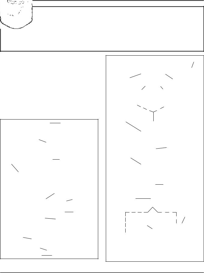
SectionCV11-164
Air CleanerCV460and Air-465,IntakeCV490System-495
Section 4
Air Cleaner and Air Intake System
Air Cleaner
These engines are equipped with a replaceable, high density paper air cleaner element and most also have the optional oiled, foam precleaner which surrounds the paper element.
Two basic types of air cleaners are used. The original configuration is shown in Figure 4-1 and the later configuration in Figure 4-2. On the original style, air is drawn through a duct from the blower housing and from the outside slot. The later type uses a flat base plate with the enclosure provided by the cover.
Air Cleaner Cover Knob
Air Cleaner Cover
Optional |
|
|
Foam |
Wing nut |
|
Precleaner |
||
|
Covered Air |
Rubber Seal |
|
(Sleeve) |
||
Cleaner Element |
||
|
||
|
Stud |
|
Hex. Flange Screw (2) |
|
Gasket
Bushing
Base
Figure 4-1. Original Air Cleaner Assembly -
Exploded View.
|
Air Duct |
|
Knob (Part |
|
4 |
of Cover) |
|
|
Air Cleaner |
|
|
Cover |
|
|
Optional Foam
Precleaner
Wing Nut
Paper Element
(Extra Capacity
Shown)
Inner Air
Cleaner Seal
Stud
Air Cleaner
Base Seal
Gasket
Open Base |
Closed Base |
Figure 4-2. Later Style Air Cleaner Assemblies -
Exploded View.
4.1

Section 4
Air Cleaner and Air Intake System
On these, air is drawn in around the bottom of the cover, or from the blower housing, rather than from slots. The flat base allows debris to be brushed away before the paper element is removed. All types can use either the standard size element or a higher, extra capacity paper element.
The original type uses a separate cover retaining knob which has to be turned completely off to remove the cover. With the later style, the knob snaps into the cover and is turned counterclockwise until it disengages the stud. Other differences are pointed out in the exploded views.
Service
Check the air cleaner daily or before starting the engine. Check for and correct any buildup of dirt and debris, and loose or damaged components.
NOTE: Operating the engine with loose or damaged air cleaner components could allow unfiltered air into the engine, causing premature wear and failure.
Precleaner Service
If so equipped, wash and reoil the precleaner every 25 hours of operation (more often under extremely dusty or dirty conditions).
1.Remove the precleaner from the paper element.
2.Wash the precleaner in warm water with detergent. Rinse the precleaner thoroughly until all traces of detergent are eliminated. Squeeze out excess water (do not wring). Allow the precleaner to air dry.
3.Saturate the precleaner with new engine oil. Squeeze out all excess oil.
4.Reinstall the precleaner over the paper element.
5.Reinstall air cleaner cover and tighten the retaining knob.
Paper Element Service
Every 100 hours of operation (more often under extremely dusty or dirty conditions), check the paper element. Clean or replace the element as necessary.
1.Remove the wing nut and air cleaner element.
2.Remove the precleaner (if so equipped) from the paper element.
3.Gently tap the flat side of the paper element to dislodge dirt. Do not wash the paper element or use pressurized air, as this will damage the element. Replace a dirty, bent, or damaged element with a genuine Kohler element. Handle new elements carefully; do not use if the sealing surfaces are bent or damaged.
4.Inspect the rubber seal (sleeve) on the stud. If it is worn, damaged, or questionable, replace it. A new seal comes packed with each replacement element.
5.Reinstall the precleaner, paper element, wing nut, and air cleaner cover. Make sure the knob is tightened securely.
Inspect Air Cleaner Components
Whenever the air cleaner cover is removed, or the paper element or precleaner are serviced, check the following areas/components:
Air Cleaner Base - Make sure the base is secured and not cracked or damaged. Since the air cleaner base and carburetor are secured to the intake port with common hardware, it is extremely important that the nuts securing these components are tight at all times.
Before reinstalling an air cleaner base that has been removed, make sure the metal bushings in the base mounting holes are present. See Figure 4-3. The bushings prevent damage to the base and maintain the proper mounting torque.
Bushings
Figure 4-3. Bushings in Air Cleaner Base.
Breather Tube - Make sure the tube is attached to both the air cleaner base and valve cover.
4.2

Section 4
Air Cleaner and Air Intake System
NOTE: Damaged, worn, or loose air cleaner components can allow unfiltered air into the engine causing premature wear and failure. Tighten or replace all loose or damaged components.
Disassembly
The following procedure is for complete disassembly of all air cleaner components.
1.Loosen the air cleaner cover retaining knob and remove the air cleaner cover.
2.Remove the wing nut and air cleaner element.
3.If so equipped, remove the precleaner from the paper element.
4.Disconnect the breather hose from the air cleaner base.
5.Remove the air cleaner base mounting nuts, air cleaner base, and gasket.
6.If necessary, remove the self-tapping screws and stud from the air cleaner base.
Reassembly
The following procedure is for complete assembly of all air cleaner components.
1.Install the stud and self-tapping screws to the air cleaner base.
2.Install the gasket, air cleaner base, and base mounting nuts. Torque the nuts to 9.9 N·m (88 in. lb.).
3.Connect the breather hose to the air cleaner base and valve cover. Secure with hose clamps.
4.If so equipped, install the precleaner (washed and oiled) over the paper element.
5.Install the air cleaner element and wing nut. Thread the wing nut on the stud until it contacts the metal cap on the element, then tighten an additional 1/2-1 turn.
6.Install the air cleaner cover. Tighten the knob securely.
Air Intake/Cooling System
Clean Air Intake/Cooling Areas
To ensure proper cooling, make sure the grass screen, cooling fins, and other external surfaces of the engine are kept clean at all times.
Every 100 hours of operation (more often under extremely dusty, dirty conditions), remove the blower housing and other cooling shrouds. Clean the cooling fins and external surfaces as necessary. Make sure the cooling shrouds are reinstalled.
NOTE: Operating the engine with a blocked grass |
4 |
screen, dirty or plugged cooling fins, and/or cooling shrouds removed, will cause engine damage due to overheating.
Air Intake Filter (Optional)
Some engines used under extremely dusty conditions such as floor buffer applications are equipped with a foam air filter which fits over the retractable starter. The filter is held in place by velcro studs affixed to the starter cover. This filter must be checked daily before each start and frequently during operation. It should be serviced whenever wax, dust, or dirt builds up on its surface. If it becomes clogged, the engine can not receive sufficient cooling air and will overheat.
To service, peel the filter loose from the velstuds, lift the filter and carefully work the recoil starter handle through the hole in filter. Clean the filter in soap and warm water, rinse, squeeze out excess water and allow it to air dry. If time will not permit air drying, keep a spare filter on hand (Kohler Part No. 12 050 02-S). When reinstalling, make sure the foam filter seals against the blower housing around its base and is securely attached to the velstuds.
4.3

Section 4
Air Cleaner and Air Intake System
4.4

SectionCV11-165
FuelCV460System-465,andCV490Governor-495
Section 5
Fuel System and Governor
Gasoline fuel systems are covered in the first part of this section. LPG (liquefied propane gas) systems and the Kohler Emission Sentry™ LPG system are covered starting on page 5.11. The governor systems start on page 5.14.
Fuel Recommendations (Gasoline)
 WARNING: Explosive Fuel!
Gasoline is extremely flammable and its vapors can explode if ignited. Store gasoline only in approved containers, in well ventilated, unoccupied buildings, away from sparks or flames. Do not fill the fuel tank while the engine is hot or running, since spilled fuel could ignite if it comes in contact with hot parts or sparks from ignition. Do not start the engine near spilled fuel. Never use gasoline as a cleaning agent.
General Recommendations (Gasoline)
Purchase gasoline in small quantities and store in clean, approved containers. A container with a capacity of 2 gallons or less with a pouring spout is recommended. Such a container is easier to handle and helps eliminate spillage during refueling.
Do not use gasoline left over from the previous season, to minimize gum deposits in your fuel system and to insure easy starting.
Do not add oil to the gasoline.
Do not overfill the fuel tank. Leave room for the fuel to expand.
Fuel Type (Gasoline)
For best results, use only clean, fresh, unleaded gasoline with a pump sticker octane rating of 87 or higher. In countries using the Research method, it should be 90 octane minimum.
Unleaded gasoline is recommended, as it leaves less combustion chamber deposits. Leaded gasoline may be used in areas where unleaded is not available and exhaust emissions are not regulated. Be aware however, that the cylinder head will require more
frequent service.
5
Gasoline/Alcohol blends
Gasohol (up to 10% ethyl alcohol, 90% unleaded gasoline by volume) is approved as a fuel for Kohler engines. Other gasoline/alcohol blends are not approved.
Gasoline/Ether blends
Methyl Tertiary Butyl Ether (MTBE) and unleaded gasoline blends (up to a maximum of 15% MTBE by volume) are approved as a fuel for Kohler engines. Other gasoline/ether blends are not approved.
Fuel System (Gasoline)
The typical fuel system includes the fuel tank, in-line fuel filter, fuel pump, carburetor, and fuel lines. Some applications use gravity feed without a fuel pump.
Operation
The fuel from the tank is moved through the in-line filter and fuel lines by the fuel pump. On engines not equipped with a fuel pump, the fuel tank outlet is located above the carburetor inlet and gravity moves the fuel.
Fuel then enters the carburetor float bowl and is moved into the carburetor body. There, the fuel is mixed with air. This fuel-air mixture is then burned in the engine combustion chamber.
Troubleshooting
Use the following procedure to check for a suspected fuel delivery problem.
5.1

Section 5
Fuel System and Governor
Fuel System Troubleshooting Guide (Gasoline)
Test |
Conclusion |
|
|
1. Check for the following: |
|
a. Make sure the fuel tank contains clean, fresh, |
|
proper fuel. |
|
b. Make sure the vent in fuel cap is open. |
|
c. Make sure the fuel valve is open. |
|
|
|
2. Check for fuel in the combustion chamber. |
2. If there is fuel at the tip of the spark plug, fuel is |
a. Disconnect and ground spark plug lead. |
reaching the combustion chamber. |
b. Close the choke on the carburetor. |
|
c. Crank the engine several times. |
If there is no fuel at the tip of the spark plug, check |
d. Remove the spark plug and check for fuel at |
for fuel flow from the fuel tank (Test 3). |
the tip. |
|
|
|
3. Check for fuel flow from the tank to the fuel pump. |
3. If fuel does flow from the line, reconnect line and |
a. Remove the fuel line from the inlet fitting of |
check for faulty fuel pump (Test 4). |
the fuel pump. |
|
b. Hold the line below the bottom of the tank. |
If fuel does not flow from the line, check for |
Open the shutoff valve (if so equipped) and |
clogged fuel tank vent, fuel pickup screen, shutoff |
observe flow. |
valve, and fuel lines. |
|
|
4. Check the operation of fuel pump. |
4. If fuel does flow from the line, check for faulty |
a. Remove the fuel line from the inlet fitting of |
carburetor. (Refer to the "Carburetor" portions of |
the carburetor. |
this section.) |
b. Crank the engine several times and observe |
|
flow. |
If fuel does not flow from the line, check for |
|
clogged fuel line. If the fuel line is unobstructed, the |
|
fuel pump is faulty and must be replaced. |
Fuel Filter
Some engines are equipped with an in-line fuel filter. Visually inspect the filter periodically, and replace when dirty with a genuine Kohler filter.
Fuel Pump
Some engines are equipped with an optional mechanical fuel pump.
The fuel pump body is constructed of nylon. The nylon body insulates the fuel from the engine crankcase. This prevents the fuel from vaporizing inside the pump.
Operation
The mechanical pump is operated by a lever which rides on the engine camshaft. The lever transmits a pumping action to the diaphragm inside the pump body. On the downward stroke of the diaphragm, fuel is drawn in through the inlet check valve. On the upward stroke of the diaphragm, fuel is forced out through the outlet check valve. See Figure 5-1.
Outlet Check Valve
Camshaft
Fuel Pump
Lever
Diaphragm
Inlet Check Valve
Figure 5-1. Cutaway - Typical Fuel Pump.
5.2
 Loading...