


 Loading...
 KIA SEDONA
WORKSHOP MANUAL

CHAPTERS
1.GENERAL INFORMATION
2.ENGINE ELECTRICAL SYSTEM
3.ENGINE MECHANICAL SYSTEM
4.EMISSION CONTROL SYSTEM
5.FUEL SYSTEM
6.SUSPENSION SYSTEM
7.DRIVESHAFTS AND AXES
8.BRAKE SYSTEM
9.MANUAL TRANSAXEL SYSTEM
10.AUTOMATIC TRANSAXEL SYSTEM
11.STEERING SYSTEM
12.HEATING, VENTILATION, AND AIRCON
13.SEATBELTS
14.BODY INTERIOR AND EXTERIOR
15.BODY ELECTRICAL SYSTEM
16.ADDED EXTRA CHANGING THE CAM BELT ON A 2.9 DIESEL ENGINE
Sedona [GQ] > 2004 > Engine > 3.5 V6
Fundamental procedures
Symbols
There are six primary symbols used to complement illustrations. These symbols indicate the areas to apply such materials during service.
Symbol |
Meaning |
Type |
|
Apply oil |
New engine oil, gear oil, etc. as appropriate |
Apply brake fluid |
Only brake fluid |
Apply automatic transmission fluid (ATF) |
Only ATF |
Apply grease |
Appropriate grease |
SEDONAApply sealant MANUALAppropriate sealant
Apply petroleum jelly |
Appropriate petroleum jelly |
|
|
Whenever special oil or grease is required, it will be identified in figure.
NOTICES, CAUTIONS AND WARNINGS
As you read through the various procedures, you will encounterNotices,CautionsandWarnings. Each one is there for a specific purpose.Noticesgive you added information that will assist you in completing a particular procedure.Cautionsprevent you from making an error that could damage the vehicle.Warningsremind you to be especially careful in specific areas where carelessness can cause personal injury.
The following items contain general procedures you should always follow when working on a vehicle:
PROTECTION OF VEHICLE
Always cover fenders, seats, and floor areas before starting work. Operate the engine only in a well-ventilated area to avoid carbon monoxide poisoning.
A WORD ABOUT SAFETY
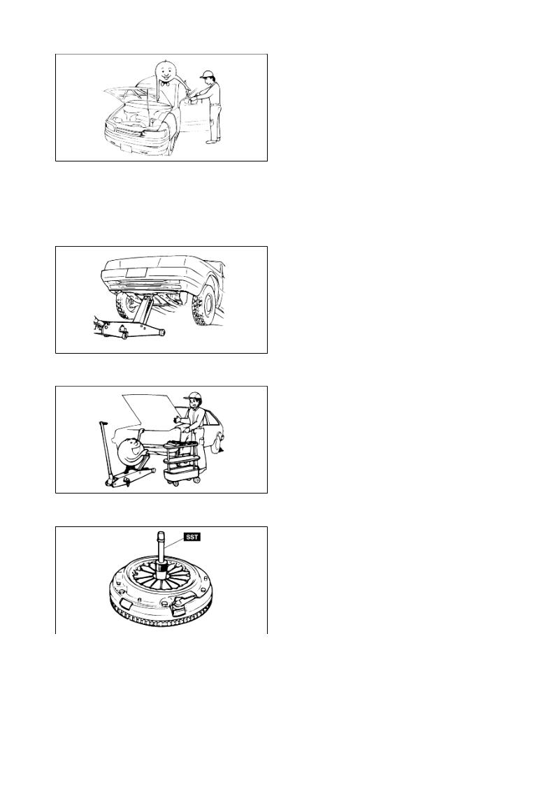
The following precautions must be followed when jacking up the vehicle:
1.Block the wheels.
2.Use only the specified jacking positions.
3.Support the vehicle with safety stands.
The engine compartment must be clear of tools and people before starting the engine.
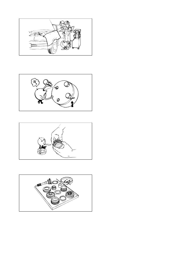
PREPARATION OF TOOLS AND MEASURING EQUIPMENT
All necessarySEDONAtools and measuring equipment should be available beforeMANUALstarting any work.
SPECIAL SERVICE TOOLS (SST'S)
Use special service tools when they are required. SST's can be found under "preparation"prior to any procedure requiring them.
REMOVAL OF PARTS
Begin work only after first learning which parts and subassemblies must be removed and disassembled for replacement or repair.
DISASSEMBLY
If the disassembly procedure is complex, requiring many parts to be disassembled, all parts should be disassembled in a way that will not affect their performance or external appearance. Additionally, these parts should be identified so that reassembly can be done easily and efficiently.
INSPECTION OF PARTS
When removed, each part should be carefully inspected for malfunction, deformations, damage, or other problems.
SEDONA MANUAL
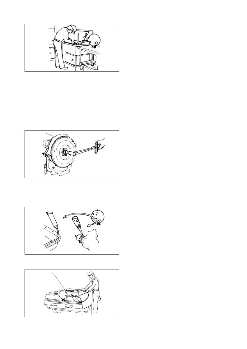
Arrangement of parts
All disassembled parts should be carefully arranged for reassembly. Separate or otherwise identify the parts to be replaced from those that will be reused.
CLEANING PARTS FOR REUSE
All parts that will be reused should be carefully and thoroughly cleaned using appropriate methods.
REASSEMBLY
Standard values, such as torques and certain adjustments, must be strictly observed in the reassembly of all parts. If removed, the following parts should be replaced with new ones:
1.Oil seals
2.O-rings
3.Cotter pins
4.Gaskets
5.Lock washers
6.Nylon nuts
SEDONA MANUAL
DEPENDING ON LOCATION:
1.Sealant should be applied or new gaskets installed.
2.Oil should be applied to the moving components of parts.
3.Specified oil or grease should be applied at the appropriate locations (such as oil seals) before reassembly.
Adjustments
Use appropriate gauges and/or testers when making adjustments.
Rubber parts and tubing
Prevent gasoline or oil from contacting rubber parts or tubing.
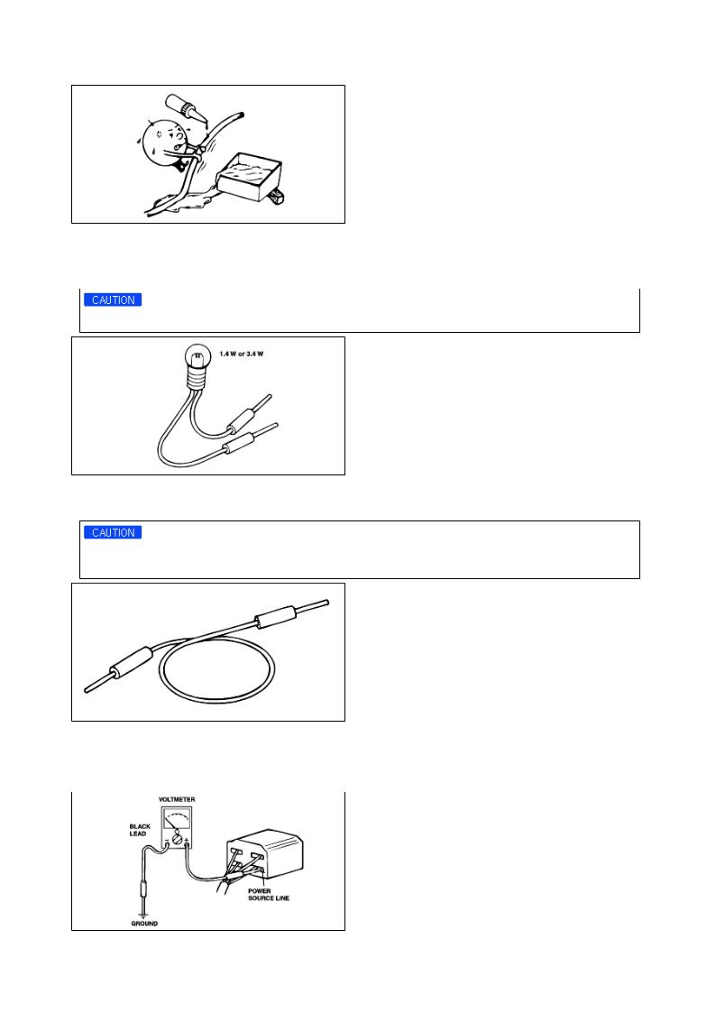
Electrical troubleshooting tools (Test Light)
The test light, as shown in figure, uses a 12V bulb. The two lead wires should be connected to probes. The test light is used for simple voltage checks and in checking for short circuits.
When checking the engine control module (ECM), never use a bulb exceeding 3.4W.
ElectricalSEDONAtroubleshooting tools(Jumper wire) MANUAL
The jumper wire is used for testing by shorting across switch terminals and ground connections.
Do not connect a jumper wire from the power source line to a body ground. Such a connection may cause damage to harnesses or electronic components.
VOLTMETER
The DC voltmeter measures circuit voltage. A voltmeter with a range of 15V or more is used by connecting the positive (+) probe (red lead wire) to the point where voltage is to be measured, and the negative (-) probe (black lead wire) to a body ground.
OHMMETER
The ohmmeter is used to measure the resistance between two points in a circuit and also to check for continuity and the diagnosis of short circuits.
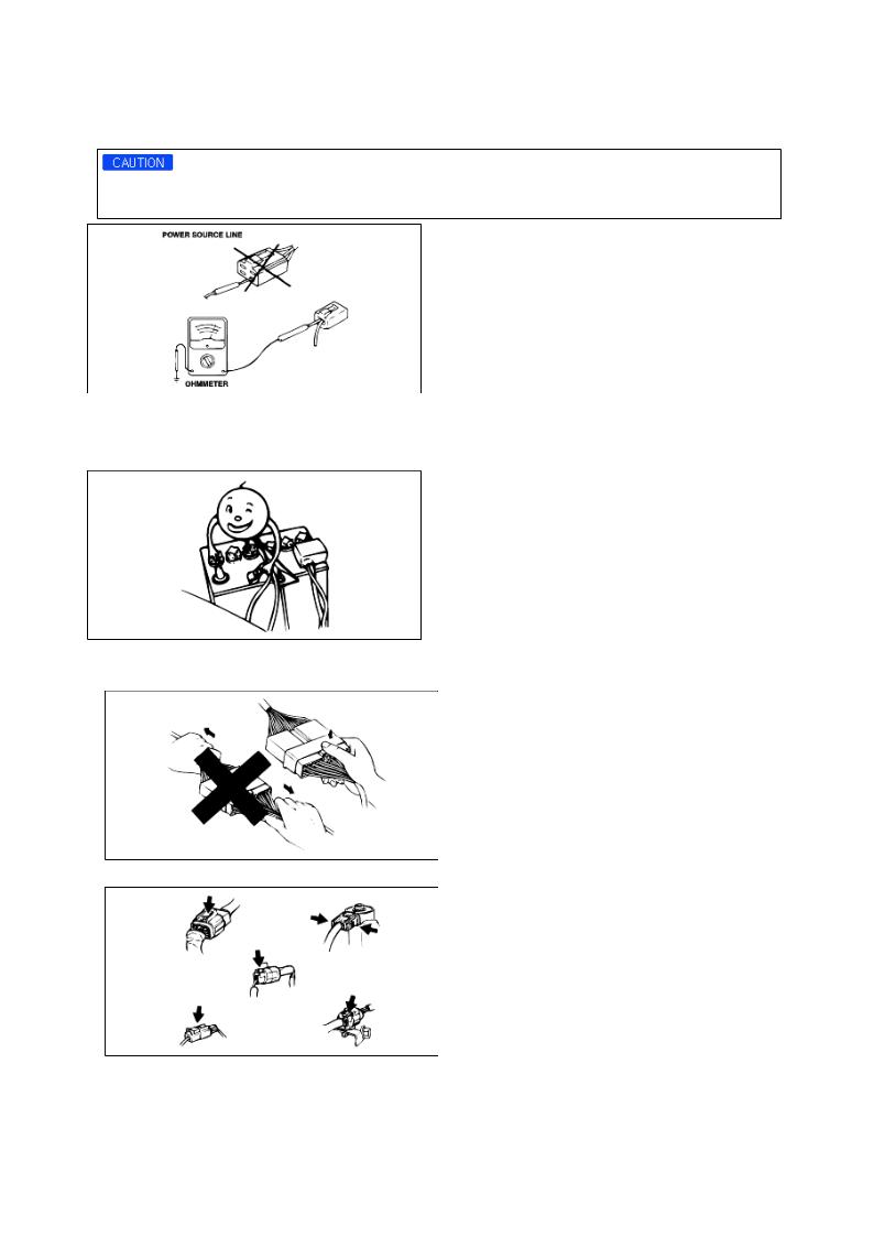
Do not attempt to connect the ohmmeter to any circuit in which voltage is applied. Such a connection may damage the ohmmeter.
Electrical parts
Battery cable
Before disconnecting connectors or replacing electrical parts, disconnect the negative battery cable.
SEDONA MANUAL
Connectors(Removal of connector)
1. Never pull on the wiring harness when disconnecting connectors.
2. Connectors can be removed by pressing or pulling lock lever.
Connectors(Locking a connector)
Listen for a click when locking connectors. This sound indicates that they are securely locked.
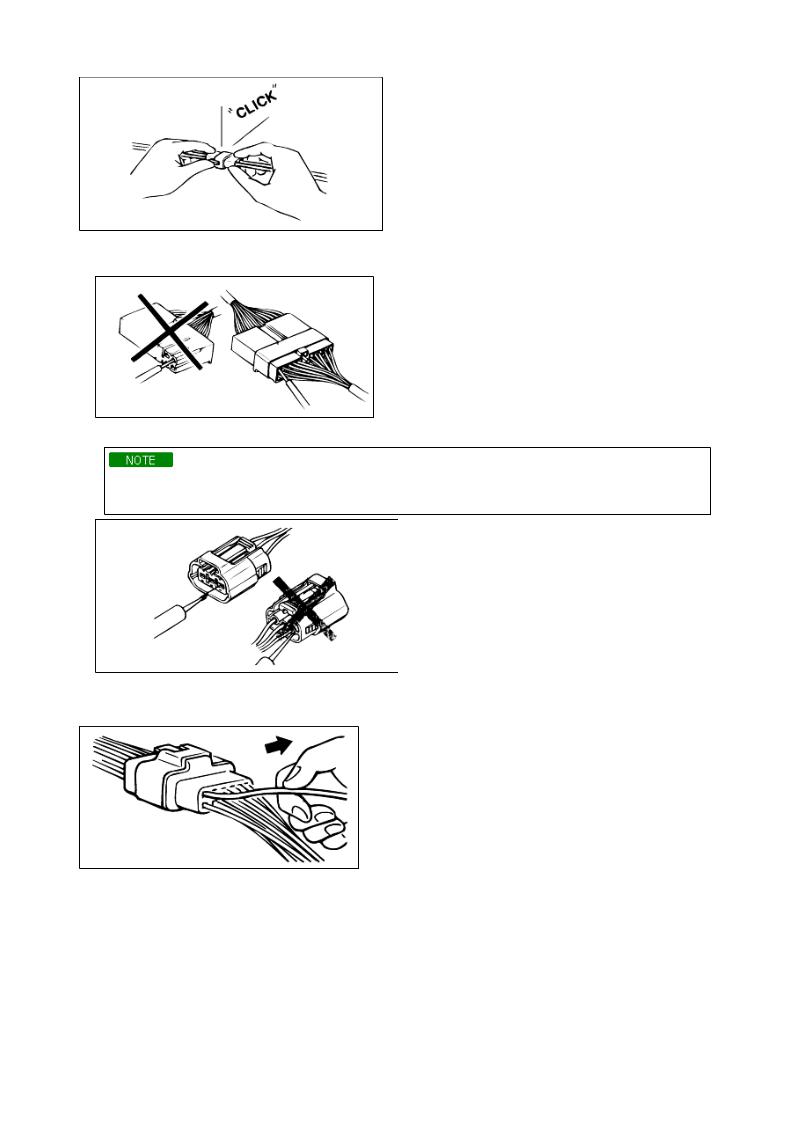
Connectors(Inspection)
1. When a tester is used to check for continuity or to measure voltage, insert tester probe from wire harness side.
2.Check terminals of waterproof connectors from connector side because they cannot be accessed from harness side.
1)Use a fine wire to prevent damage to the terminal.
2)Do not damage the terminal when inserting the tester lead.
SEDONA MANUAL
Terminals(Inspection)
Pull lightly on individual wires to ensure that they are secured in the terminal.
REPLACEMENT OF TERMINALS
Use appropriate tools to remove terminal as shown. When installing the terminal, insert it until it locks securely.
FEMALE
Insert a thin piece of metal from the terminal side of the connector, and then, with the terminal locking tab pressed down, pull the terminal out of the connector.
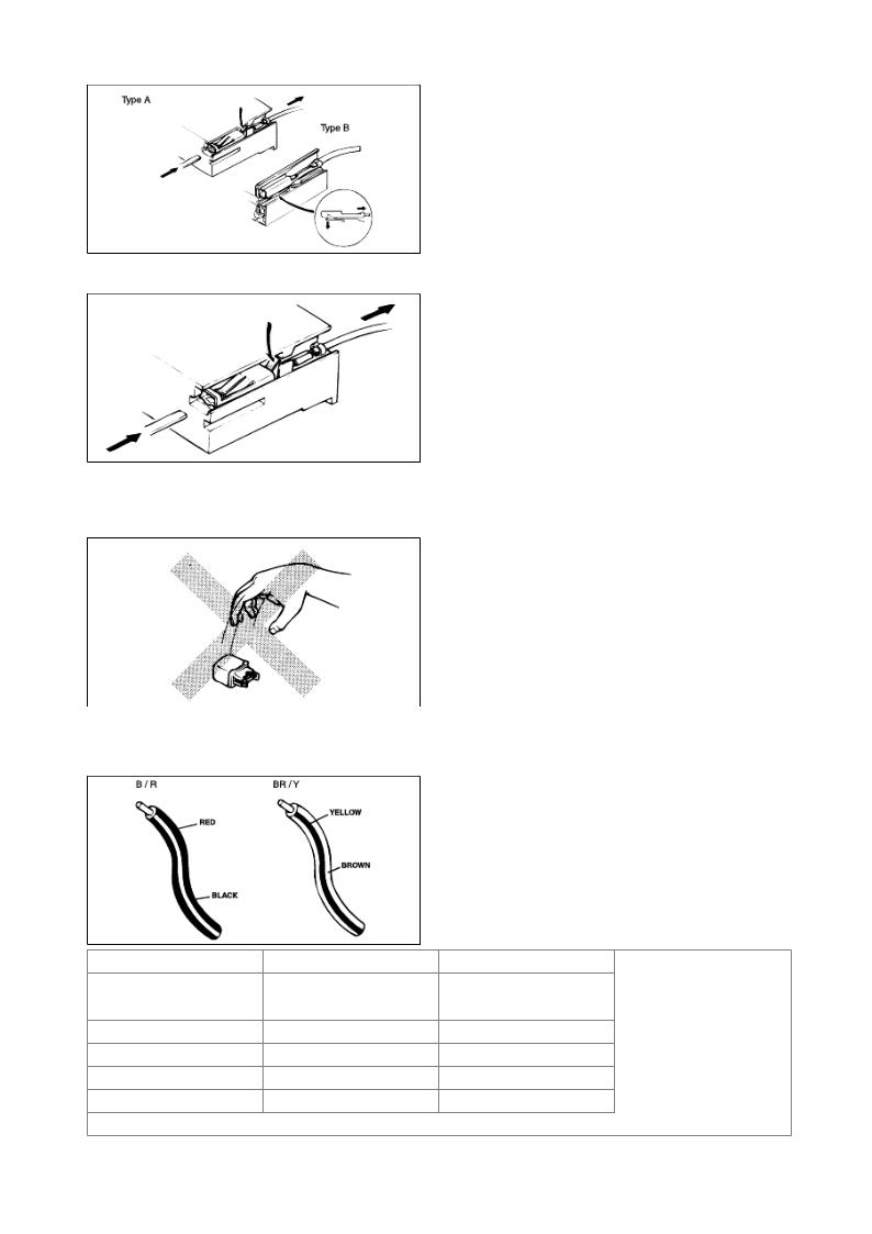
MALE
Follow the same procedure as female-type terminal.
SENSORS, SWITCHES, AND RELAYS
Always handle sensors, switches and relays carefully.
Do not drop them or accidentally strike them against other parts.
SEDONA MANUAL
WIRING COLOR CODES
Two-color wires are indicated by a two-color code sysmbol. The firstcolor indicates the base color of the wire; the second color indicates the color of the stripe.
CODE |
COLOR |
CODE |
COLOR |
B |
BLACK |
P |
PINK |
|
|
|
|
BR |
BROWN |
R |
RED |
|
|
|
|
G |
GREEN |
S |
SILVER(LIGHT BLUE) |
|
|
|
|
GY |
GRAY |
T |
TAWNY |
|
|
|
|
L |
BLUE |
V |
VIOLET |
|
|
|
|
LG |
LIGHT GREEN |
W |
WHITE |
|
|
|
|
O |
ORANGE |
Y |
TELLOW |
|
|
|
|
JACK POSITIONS
Front end jack position:
At the center of the sub-frame.
Rear end Jack position:
At the center of the rear axle.
VEHICLE LIFT (2-SUPPORT TYPE) AND SAFETY STAND POSITIONS
Front SEDONAend / Rear end MANUAL
towing
Proper towing equipment is necessary to prevent damage to the vehicle. Always observe laws and regulations applicable to vehicles in tow. As a general rule, towed vehicles should be pulled with the driving wheels off the ground. If excessive damage or other conditions prevent towing the vehicle with the driving wheels off the ground, use wheel dollies.
With either automatic or manual transmission:
1.Set the ignition switch in the ACC position.
2.Place the selector lever or shift lever in N (Neutral).
3.Release the parking brake.
1)Do not tow vehicle backward with driving wheels on the ground. This may cause internal damage to transmission.
2)Do not use hook loops under the front and rear of the vehicle for towing purposes. These hook loops are designed ONLY for transport tie-down. If tie-down hook loops are used for towing, the front/rear bumper will be damaged.
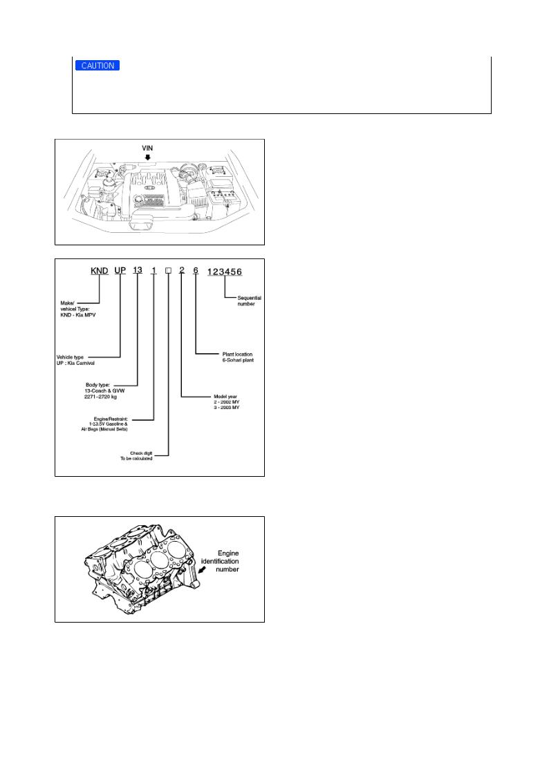
VIN LOCATIONS
Vehicle identification number arrangement
SEDONA MANUAL
ENGINE NUMBER LOCATIONS
SIGMA 3.5
Transaxle number locations SIGMA 3.5
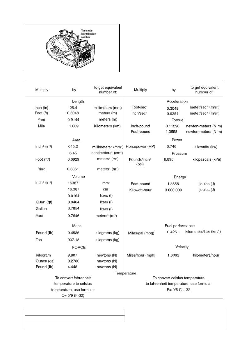
English/Metric conversion table
SEDONA MANUAL
UNITS
ft-lb or in-lb (N·m) |
Torque |
|
|
rpm |
Rotational speed |
|
|
|
|
A |
Amperes |
|
V |
Volts |
|
|
|
|
Ω |
Resistance |
|
|
|
|
psi (kPa) |
Pressure |
|
|
|
|
inHg (mmHg) |
Pressure (usually negative vacuum) |
|
|
|
|
W |
Watts |
|
(electrical power) |
||
|
||
|
|
|
US qt (liters) |
Volume |
|
|
|
|
in (mm) |
Length |
|
|
|
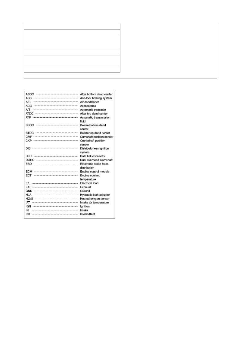
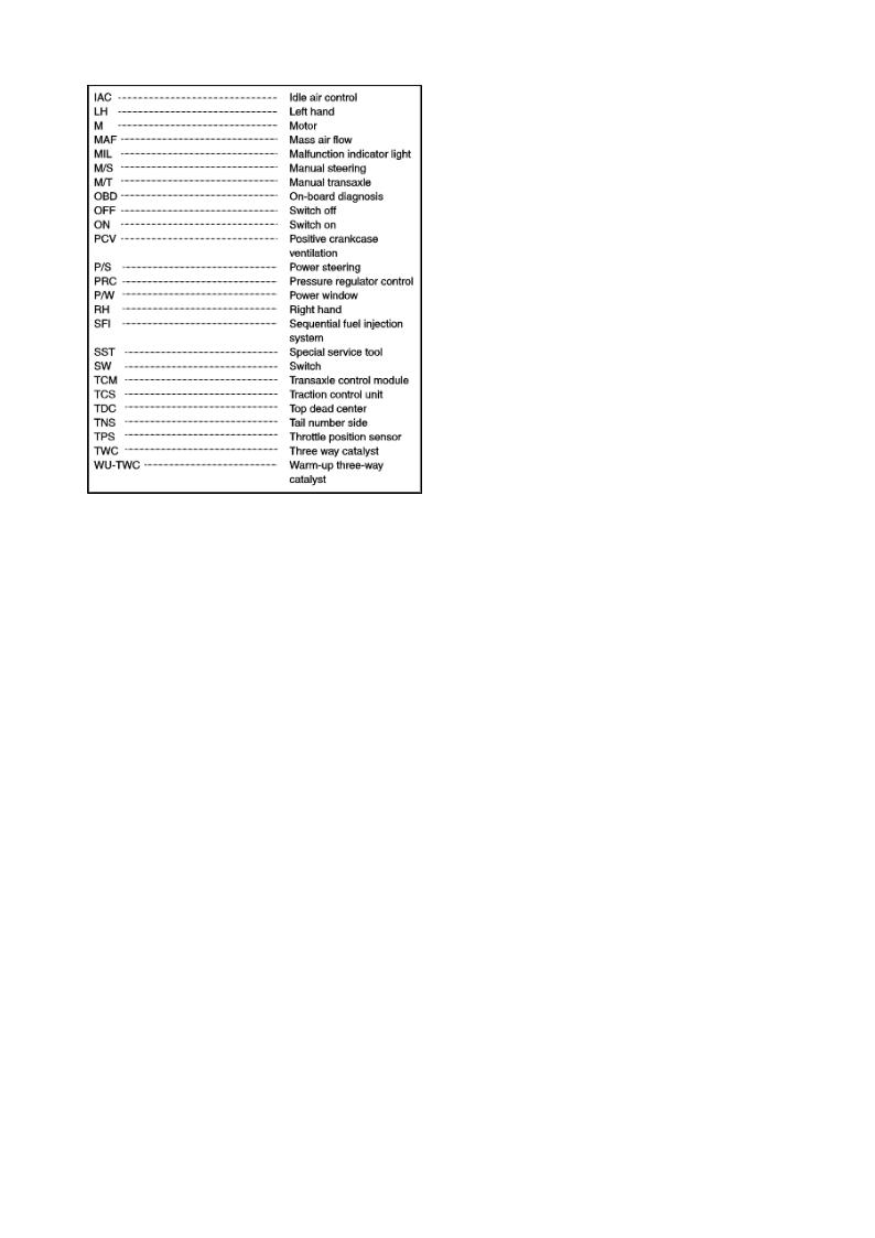
ABBREVIATIONS
SEDONA MANUAL
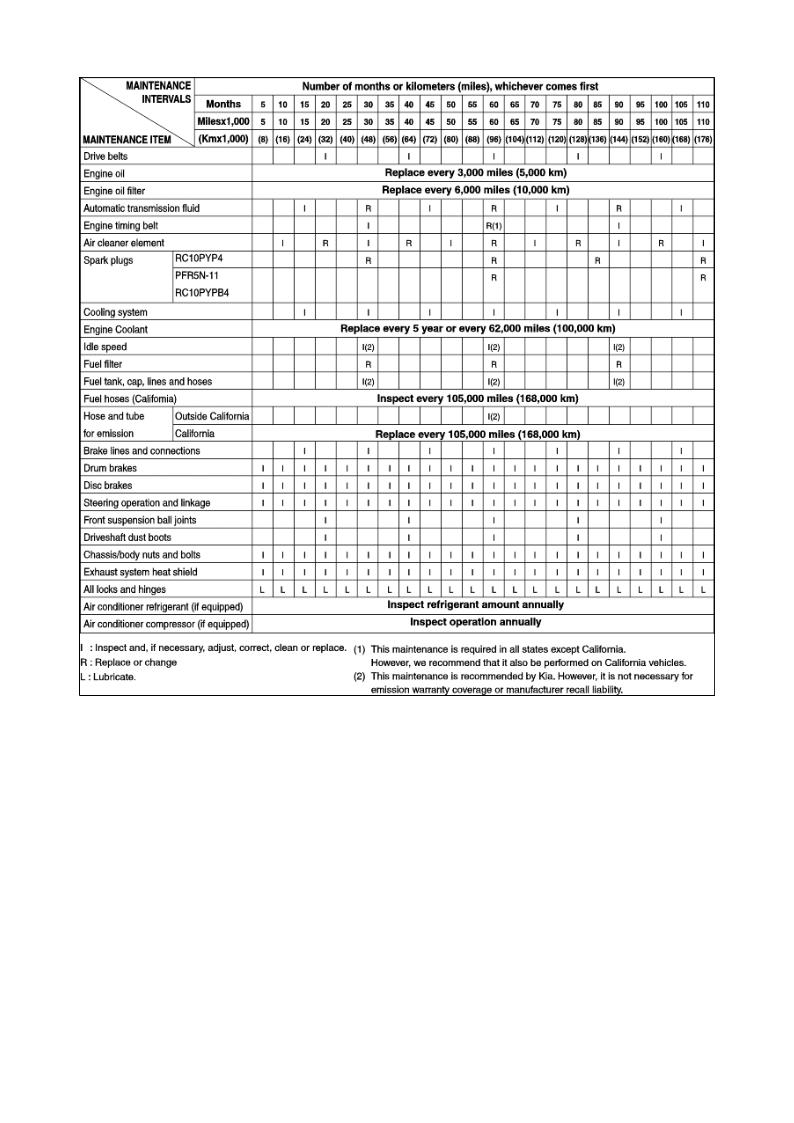
MAINTENANCE SCHEDULE
SEDONA MANUAL
SEDONA MANUAL
MAINTENANCE SCHEDULE

SEDONA MANUAL

Engine Electrical System
SEDONA MANUAL
Sedona [GQ] > 2004 > Engine > 3.5 V6
TROUBLESHOOTING
IGNITION SYSTEM |
|
|
|
|
Probable cause |
|
|
Ignition lock switch faulty |
|
|
Ignition coil faulty |
|
|
Power transistor faulty |
|
|
Spark plugs faulty |
|
|
Ignition wiring disconnected or broken |
|
|
Spark plugs faulty |
|
|
Ignition wiring faulty |
|
|
Ignition coil faulty |
|
|
Spark plug cable faulty |
|
|
Spark plugs faulty |
|
|
Ignition wiring faulty |
Poor mileage |
|
Spark plugs faulty |
|
||
CHARGING SYSTEM |
|
|
|
|
Probable cause |
Remedy
Replace ignition lock switch Inspect ignition coil
Inspect power transistor Replace plugs
Inspect wiring Replace plugs
Inspect wiring Inspect ignition coil
Inspect spark plug cable
Replace plugs
Inspect ignition coil
Replace plugs
Remedy
|
Fuse blown |
|
Check fuses |
|
|
Light burned out |
|
Replace light |
|
|
Wiring connection loose |
|
Tighten loose connections |
|
SEDONA |
MANUAL |
|||
|
Electronic voltage regulator faulty |
Replace voltage regulator |
||
|
Drive belt loose or worn |
|
Adjust tension or replace drive |
|
|
Battery cables loose, corroded or worn |
belt |
||
|
Fuse blown |
|
Repair or replace cables |
|
|
Fusible link blown |
|
Check fuses |
|
|
Electronic voltage regulator or generator |
Replace fusible link |
||
|
faulty |
|
Test generator |
|
|
Wiring faulty |
|
Repair wiring |
|
|
|
|
|
|
|
Drive belt loose or worn |
|
Adjust tension or replace drive |
|
|
|
belt |
||
|
Wiring connection loose or open circuit |
Tighten loose connection or |
||
|
Fusible link blown |
|
repair wiring |
|
Engine hesitates/poor |
Poor grounding |
|
Replace fusible link |
|
acceleration |
Electronic voltage regulator or generator |
Repair |
||
Overcharge |
faulty |
|
Test generator, if faulty, repair |
|
|
Worn battery |
|
or replace |
|
|
Electronic voltage regulator faulty |
Replace battery |
||
|
Voltage sensing wire faulty |
Replace voltage regulator |
||
|
|
|
Repair wire |
|
STARTING SYSTEM |
|
|
|
|
|
Probable cause |
Remedy |
||
|
Battery charge low |
|
|
|
|
|
|
||
|
Battery cables loose, corroded or worn out |
Charge or replace battery |
||
Engine will not crank |
Transaxle range switch faulty (Vehicle with |
Repair or replace cables |
||
automatic transaxle only) |
Adjust or replace switch |
|||
|
||||
|
Fusible link blown |
|
Replace fusible link |
|
|
Starter motor faulty |
|
Repair starter motor |
|
|
|
|
|
|
|
Ignition switch faulty |
Replace ignition switch |
|
Ignition lock switch faulty |
Replace ignition lock switch |
|
|
|
|
Battery charge low |
Charge or replace battery |
|
Battery cables loose, corroded or worn out |
Repair or replace cables |
|
Starter motor faulty |
Repair starter motor |
|
|
|
|
Starter motor faulty |
Repair starter motor |
|
Ignition switch faulty |
Replace ignition switch |
|
|
|
|
Short in wiring |
Repair wiring |
Starter spins but engine will not |
Pinion gear teeth broken or starter motor |
Repair starter motor |
crank |
faulty |
Replace flywheel ring gear or |
|
Ring gear teeth broken |
torque converter |
|
|
|
SEDONA MANUAL
Sedona [GQ] > 2004 > Engine > 3.5 V6
SPECIFICATIONS
IGNITION |
|
|
Type |
|
Mold coil |
|
||
Primary coil resistance |
|
0.78 (Ω) |
Secondary coil resistance |
|
13.0 ± 2.6 (Ω) |
SPARK PLUG |
|
|
|
|
PFR5N-11 |
|
|
RC10PYPB4 |
|
|
|
Plug gap |
|
1.0-1.1 mm (0.039-0.043 in.) |
STARTER MOTOR |
|
|
|
|
Reduction drive (with planetary gear) |
|
|
12V |
|
|
1.2 KW |
|
|
|
|
|
11V |
|
|
90A or below |
|
|
3,000 RPM MIN |
8
PinionSEDONAgap 0.5-2.0 mm (0MANUAL.0197-0.079 in.)
GENERATOR
Type |
|
Battery voltage sensing |
Rated output |
|
13.5V / 120A |
Voltage regulator type |
|
Electronic built-in type |
Regulator setting voltage |
|
14.4 ± 0.3 V |
Temperature compensated |
|
-10 ± 3 mV/°C |
BATTERY |
|
|
Type |
|
55-26 FL (MF) |
|
||
Ampere hours |
|
|
|
70AH |
|
20HR |
|
|
|
600A |
|
Cold cranking [at -18°C (0°F)] |
|
|
|
113 min. |
|
Reverse capacity |
|
|
|
1.280 ± 0.01 |
|
Specific gravity [at 25°C (77°F)] |
|
|
|
|
|
|
|
|
COLD CRANKING AMPERAGE is the amperage a battery can deliver for 30 seconds and maintain a terminal voltage of 7.2 or greater at a specified temperature. REVERSE CAPACITY RATING is the amount of time a battery can deliver 25A and maintain a minimum terminal voltage of 10.5 at 26.7°C (80°F).
CRUISE CONTROL SYSTEM
Speed control module |
DC 11 - 16V |
Operating voltage range |
-40~110°C |
Operating temperature |
0.4V |
Voltage drop between unit and actuator |
Low speed limit : 20~24 mile |
|
|
Operating speed range |
High speed limit : 116~120 mile |
|
|
|
||
TIGHTENING TORQUE |
|
|
|
|
|
|
|
N·m |
Kg·cm |
Ib·ft |
|||
|
|
|
|
|
|
|
Generator terminal (B+) |
5 |
- 7 |
50 |
- 70 |
3.6 |
- 5.1 |
Starter motor terminal (B+) |
10 |
- 12 |
100 |
- 120 |
7.3 |
- 8.8 |
Battery terminal |
4 |
- 6 |
40 |
- 60 |
2.9 |
- 4.3 |
Spark plug |
20 |
- 30 |
200 |
- 300 |
15 |
- 22 |
|
|
|
|
|
|
|
SEDONA MANUAL
Sedona [GQ] > 2004 > Engine > 3.5 V6
GENERAL INFORMATION
lgnition timing is controlled by the electric control ignition timing system. The ignition timing data for the engine operating conditions are programmed in the memory of the power train control module (PCM).
The engine conditions (speed, load, warm-up condition, etc.) are detected by the various sensors. Based upon these sensor signals and the ignition timing data, signals to interrupt the primary current are sent to the power transistor. The ignition coil is activated and timing is controlled at the optimum point.
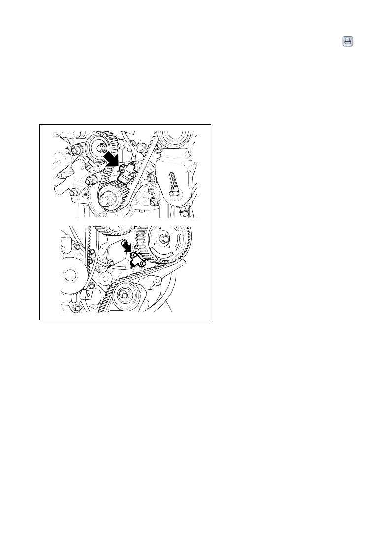
*CKP : Crankshaft Position Sensor
*CMP : Camshaft Position Sensor
SEDONA MANUAL
Sedona [GQ] > 2004 > Engine > 3.5 V6
Inspection
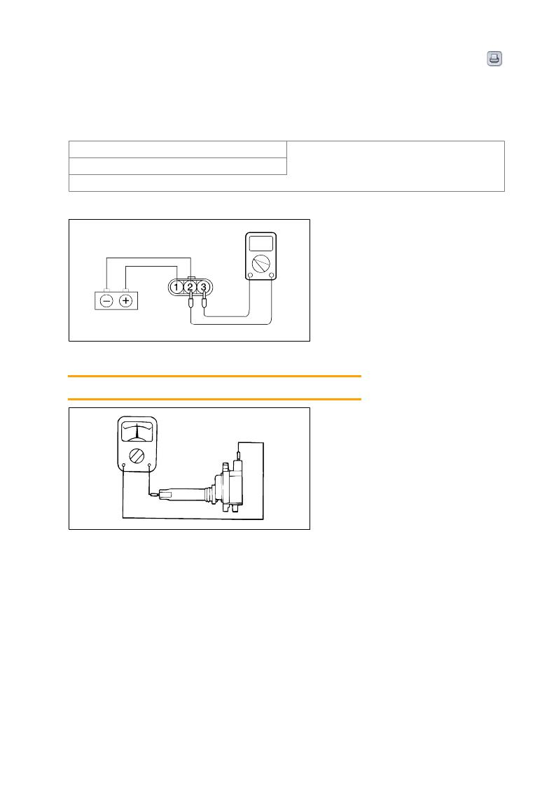
1.Measurement of the primary coil resistance
Connect the negative (-) terminal of a 3V power supply to terminal 2 of the power transistor; then check whether there is continuity between terminal 3 and terminal 2 when terminal 1 and the positive (+) terminal are connected and disconnected.
|
Terminal 3 and terminal 2 |
|
Continuity (0.78Ω ± 10%) |
|
|
Disconnected |
Non continuity |
Replace the ignition coil if there is malfunction. |
|
2.Measurement of the secondary coil resistance
Measure the resistance between the high-voltage terminals of the ignition coil. StandardSEDONAvalue : 13.0 ± 2.6 (kΩ) MANUAL
Sedona [GQ] > 2004 > Engine > 3.5 V6
INSPECTION
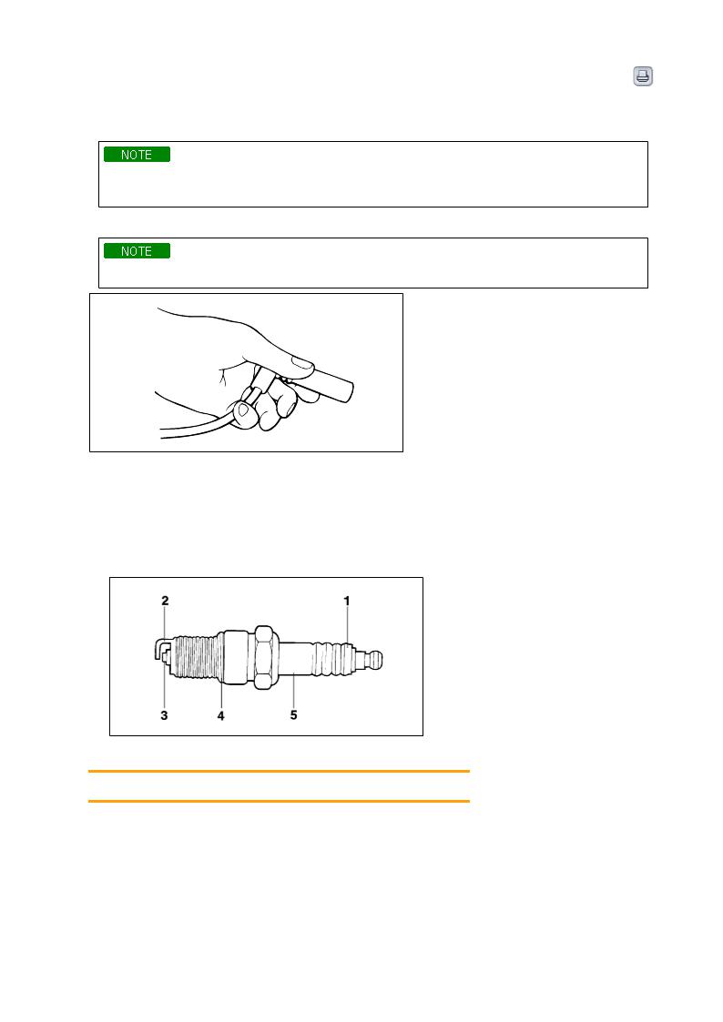
1. Disconnect the spark plug cable from the spark plug.
Pull on the spark plug cable boot when removing the spark plug cable, not the cable, as it may be damaged.
2. Using the spark plug wrench, remove all of the spark plugs from the cylinder head.
Take care not to allow contaminants to enter through the spark plug holes.
3. Check spark plugs for the following:
(2) Worn electrode
(1)SEDONABroken insulator MANUAL
(3) Carbon deposits
(4) Damaged or broken gasket
(5) Condition of the porcelain insulator at the tip of the spark plug
4.Check the spark plug gap using a wire gap gauge, and adjust if necessary. Standard valueSpark plug gap : 1.0 - 1.1 mm (0.039 - 0.043 in.)

5.Re-insert the spark plug and tighten to the specified torque. If it is overtorqued, damage to the threaded portion of cylinder head may result.
Tightening torqueSpark plug : 20 - 30 N·m (200 - 300 kg·cm, 15-22 lb·ft)
When replacing the spark plug, use the genuine parts which have resistance.
SEDONA MANUAL
SEDONA MANUAL

Sedona [GQ] > 2004 > Engine > 3.5 V6
GENERAL INFORMATION
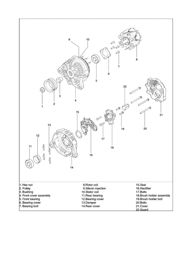
The charging system included a battery, an generator with a built-in regulator, and the charging indicator light and wire. The generator has eleven built-in diodes (four positive, four negative and three exiter diodes), each rectifying AC current to DC current. Therefore, DC current appears at generator "B" terminal.
In addition, the charging voltage of this generator is regulated by the battery voltage detection system. The generator is regulated by the battery voltage detection system. The main components of the generator are the rotor, stator, rectifier, capacitor brushes, bearings and V-ribbed belt pulley. The brush holder contains a built-in electronic voltage regulator.
SEDONA MANUAL
Sedona [GQ] > 2004 > Engine > 3.5 V6
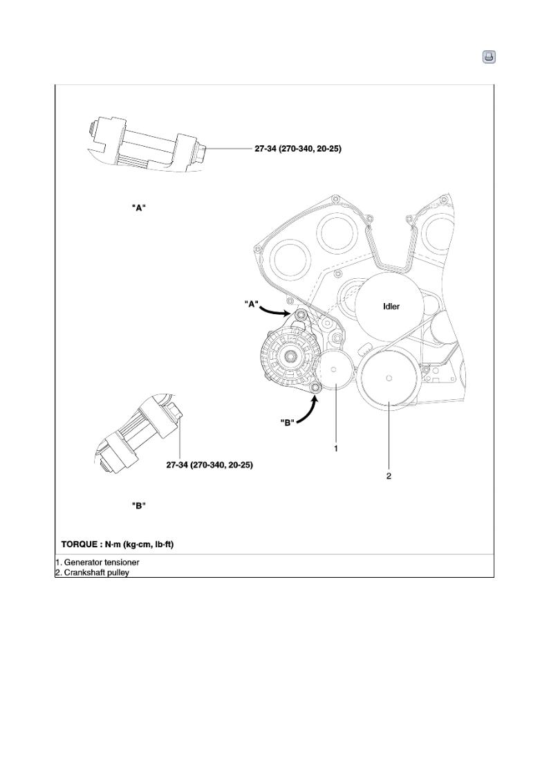
COMPONENTS
SEDONA MANUAL
COMPONENTS
SEDONA MANUAL
Loading...