


358GB
High-speed, High-capacity Machine Vision System
CV-X Series
Easy Setup Guide
Control/Communication PLC-Link
(MELSEC FX Series)

Contents
Easy Setup Guide: Control/Communication PLC-Link (MELSEC FX Series)
1. Establishing the PLC-Link (RS-232C PLC-Link) |
Page 3 |
2. Outputting the Measured Value/Judged Value (PLC-Link) |
Page 6 |
3. Controlling the Controller (PLC-Link) |
Page 9 |
Trademarks
Product names, etc. noted in this document are registered trademarks or trademarks of their respective companies. The ™ mark and ® mark have been omitted in this manual.
KEYENCE CORPORATION. Vision System Division |
2 |
www.keyence.com |
|
|
|
1. Establishing the PLC-Link (RS-232C PLC-Link) [MELSEC FX Series]
Checking the Global Settings of the CV-X Series
This section describes how to establish the PLC Link.
[Important] If it fails, follow this manual to configure the settings and check the operations. Confirm that it operates properly, and change settings if necessary.
1
2
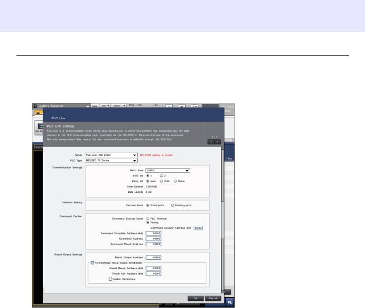
On the "Global" menu, select [Communications & I/O] > [PLC-Link].
Select "OK" to close the "PLC-Link" setting screen and then restart the controller.
Configure the PLC Link settings.
Mode: PLCLink (RS232C)
PLC Type: MELSEC FX Series Baud Rate: 19200
Stop Bit: 1 Parity Bit: Even
Flow Control: CTS/RTS Data Length: 8- bit (fixed)
* The above is a setting example. Change the settings according to the target device.
Decimal Point: Fixedpoint
Command Execute Event: Polling Command Complete Address (bit): 00003 Command Address: 00100
Command Result Address: 00200 Result Output Address: 00500 Result Ready Address (bit): 00000 Result Ack Address (bit): 00001
Acknowledge result output completion: Checked
Enable Handshake: Unchecked
[Note] The memory range that can be used varies according to the target device. Furthermore, frequently accessing a memory with EEPROM (non-volatile memory) assigned may lead to delays, and a shorter device lifespan.
Ensure that you have thoroughly checked the memory range of the device to be connected before using it.
358GB
KEYENCE CORPORATION. Vision System Division |
3 |
www.keyence.com |
|
|
|

Configuring the FX Series Settings
1
2
3
Start GX Developer, and select [Project] > [New project].
Select "FXCPU" for "Series" and a model*2 to use for "Type", and then press the "OK" button. *1 Programmable Controller *2 Select a model described in the CV-X user's manual.
Select "PLC Parameter" from the project data list, and change the parameters according to the CV-X Series Global Settings.
KEYENCE CORPORATION. Vision System Division |
4 |
|
|
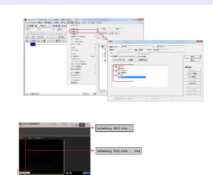
4 Select [Online] > [Write to PLC], and press "Execute" to connect to PLC.
5 Restart both the CV-X Series and the MELSEC FX Series.
* Start the MELSEC FX Series first, and then start the CV X Series.
If "Initializing PLCLink..." appears on the lower left of the screen and disappears immediately, it indicates that the link has been established successfully.
If the link establishment has failed, the message "Initializing PLCLink...
*" appears repeatedly, and the error message "Failed to establish a link with the PLC" appears.
Check the settings of the CV X Series and MELSEC FX Series again.
KEYENCE CORPORATION. Vision System Division |
5 |
www.keyence.com |
|
|
|
 Loading...