


 Loading...
VIDEO CASSETTE RECORDER
HR-S9800U
VCR TV CABLE/DBS |
A.MONITOR POWER |
||
A/B |
TV/VCR |
DISPLAY |
ENTER/OSD |
.1, ? |
|
2 |
3 |
|
ABC |
DEF |
|
|
|
|
2 |
4 |
|
5 |
6 |
DHI |
|
JKL |
MNO |
DBS |
DAILY(M-F) |
WEEKLY |
|
7 |
|
8 |
9 |
PQRS |
|
TUV |
WXYZ |
C. RESET |
|
AUX |
|
CANCEL |
|
0 |
TIMER 4 |
START |
STOP |
DATE |
CH |
EXPRESS PROGRAMMING |
|||
1 PROG |
SP/EP |
PROG |
SKIP SEARCH |
|
CHECK |
|
|
PLAY
REW
FF
STOP
REC
TV CH +
TV
VOL
–
PAUSE
TV
VOL
+
M
E
N
U
3
OK
TV CH – NAVIGATION
JOG/ SHUTTLE
INSTRUCTIONS
For Customer Use:
Enter below the Model No. and Serial No. which are located on the rear of cabinet. Retain this information for future reference.
Model No.
Serial No.
LPT0350-001A
2 EN
Dear Customer,
Thank you for purchasing the JVC S-VHS video cassette recorder. Before use, please read the safety information and precautions contained in the following pages to ensure safe use of your new VCR.
CAUTIONS
CAUTION
RISK OF ELECTRIC SHOCK
DO NOT OPEN
CAUTION: TO REDUCE THE RISK OF ELECTRIC SHOCK.
DO NOT REMOVE COVER (OR BACK).
NO USER-SERVICEABLE PARTS INSIDE.
REFER SERVICING TO QUALIFIED SERVICE PERSONNEL.
The lightning flash with arrowhead symbol, within an equilateral triangle, is intended to alert the user to the presence of uninsulated "dangerous voltage" within the product's enclosure that may be of sufficient magnitude to constitute a risk of electric shock to persons.
The exclamation point within an equilateral triangle is intended to alert the user to the presence of important operating and maintenance (servicing) instructions in the literature accompanying the appliance.
WARNING:
TO PREVENT FIRE OR SHOCK HAZARD, DO NOT EXPOSE THIS UNIT TO RAIN OR MOISTURE.
CAUTION:
This video cassette recorder should be used with AC 120V`, 60Hz only.
To prevent electric shocks and fire hazards, DO NOT use any other power source.
CAUTION:
TO PREVENT ELECTRIC SHOCK, MATCH WIDE BLADE OF PLUG TO WIDE SLOT, FULLY INSERT.
ATTENTION:
POUR ÉVITER LES CHOCS ÉLECTRIQUES, INTRODUIRE LA LAME LA PLUS LARGE DE LA FICHE DANS LA BORNE CORRESPONDANTE DE LA PRISE ET POUSSER JUSQU'AU FOND.
Declaration of Conformity
Model Number |
:HR-S9800U |
Trade Name |
:JVC |
Responsible Party |
:JVC Americas Corp. |
Address |
:1700 Valley Road Wayne, |
|
N.J. 07470 |
Telephone Number :973-315-5000
This device complies with Part 15 of FCC Rules. Operation is subject to the following two conditions:
(1) This device may not cause harmful interference, and (2) this device must accept any interference received, including interference that may cause undesired operation.
Failure to heed the following precautions may result in damage to the VCR, Remote or video cassette.
1.DO NOT place the VCR . . .
... in an environment prone to extreme temperatures or humidity.
... in direct sunlight.
... in a dusty environment.
... in an environment where strong magnetic fields are generated.
... on a surface that is unstable or subject to vibration.
2.DO NOT block the VCR’s ventilation openings.
3.DO NOT place heavy objects on the VCR or on the Remote.
4.DO NOT place anything which might spill on the top of the VCR or on the Remote.
5.AVOID violent shocks to the VCR during transport.
VCR Plus+, C3 and PlusCode are registered trademarks of Gemstar Development Corporation.
The VCR Plus+ system is manufactured under license from Gemstar Development Corporation.
DSSTM is an official trademark of DIRECTV, Inc., a unit of GM Hughes Electronics. PRIMESTAR is a registered service mark of Primestar Partners, L.P. DISH NetworkTM is a trademark of Echostar Communications Corporation.
Note to CATV system installer:
This reminder is provided to call the CATV system installer’s attention to Article 820-40 of the NEC that provides guidelines for proper grounding and, in particular, specifies that the cable ground shall be connected to the grounding system of the building, as close to the point of cable entry as practical.
CAUTION:
Changes or modifications not approved by JVC could void user’s authority to operate the equipment.
nCassettes marked “S-VHS” and “VHS” can be used with this video cassette recorder. However, S-VHS recordings are possible only with cassettes marked “S-VHS”.
By using S-VHS ET it is possible to record and play back with S-VHS picture quality on VHS cassettes with this VCR.
nAs an ENERGY STAR® Partner, JVC has determined that this product or product model meets the ENERGY STAR® guidelines for energy efficiency.

EN 3
IMPORTANT PRODUCT SAFETY INSTRUCTIONS
Electrical energy can perform many useful functions. But improper use can result in potential electrical shock or fire hazards. This product has been engineered and manufactured to assure your personal safety. In order not to defeat the built-in safeguards, observe the following basic rules for its installation, use and servicing.
ATTENTION:
Follow and obey all warnings and instructions marked on your product and its operating instructions. For your safety, please read all the safety and operating instructions before you operate this product and keep this booklet for future reference.
INSTALLATION
1. Grounding or Polarization
(A)Your product may be equipped with a polarized alternatingcurrent line plug (a plug having one blade wider than the other). This plug will fit into the power outlet only one way. This is a safety feature.
If you are unable to insert the plug fully into the outlet, try reversing the plug. If the plug should still fail to fit, contact your electrician to replace your obsolete outlet. Do not defeat the safety purpose of the polarized plug.
(B)Your product may be equipped with a 3-wire grounding-type plug, a plug having a third (grounding) pin. This plug will only fit into a grounding-type power outlet. This is a safety feature.
If you are unable to insert the plug into the outlet, contact your electrician to replace your obsolete outlet. Do not defeat the safety purpose of the grounding-type plug.
2. Power Sources
Operate your product only from the type of power source indicated on the marking label. If you are not sure of the type of power supply to your home, consult your product dealer or local power company. If your product is intended to operate from battery power, or other sources, refer to the operating instructions.
3. Overloading
Do not overload wall outlets, extension cords, or integral convenience receptacles as this can result in a risk of fire or electric shock.
4. Power Cord Protection
Power supply cords should be routed so that they are not likely to be walked on or pinched by items placed upon or against them, paying particular attention to cords at plugs, convenience receptacles, and the point where they exit from the product.
5. Ventilation
Slots and openings in the cabinet are provided for ventilation. To ensure reliable operation of the product and to protect it from overheating, these openings must not be blocked or covered.
•Do not block the openings by placing the product on a bed, sofa, rug or other similar surface.
•Do not place the product in a built-in installation such as a bookcase or rack unless proper ventilation is provided or the manufacturer’s instructions have been adhered to.
6. Wall or Ceiling Mounting
The product should be mounted to a wall or ceiling only as recommended by the manufacturer.
ANTENNA INSTALLATION
INSTRUCTIONS
1. Outdoor Antenna Grounding
If an outside antenna or cable system is connected to the product, be sure the antenna or cable system is grounded so as to provide some protection against voltage surges and built-up static charges. Article 810 of the National Electrical Code, ANSI/NFPA 70, provides information with regard to proper grounding of the mast and supporting structure, grounding of the lead-in wire to an antenna discharge unit, size of grounding connectors, location of antenna discharge unit, connection to grounding electrodes, and requirements for the grounding electrode.
2. Lightning
For added protection for this product during a lightning storm, or when it is left unattended and unused for long periods of time, unplug it from the wall outlet and disconnect the antenna or cable system. This will prevent damage to the product due to lightning and power-line surges.
3. Power Lines
An outside antenna system should not be located in the vicinity of overhead power lines or other electric light or power circuits, or where it can fall into such power lines or circuits. When installing an outside antenna system, extreme care should be taken to keep from touching such power lines or circuits as contact with them might be fatal.
EXAMPLE OF ANTENNA GROUNDING AS PER
NATIONAL ELECTRICAL CODE, ANSI/NFPA 70
ANTENNA
LEAD IN WIRE
GROUND CLAMP
ANTENNA DISCHARGE UNIT (NEC SECTION
ELECTRIC SERVICE 810-20) EQUIPMENT 

GROUNDING CONDUCTORS
(NEC SECTION 810-21)
GROUND CLAMPS
POWER SERVICE GROUNDING ELECTRODE SYSTEM (NEC ART 250. PART H)
NEC – NATIONAL ELECTRICAL CODE
4 EN
USE
1. Accessories
To avoid personal injury:
•Do not place this product on an unstable cart, stand, tripod, bracket, or table. It may fall, causing serious injury to a child or adult, and serious damage to the product.
•Use only with a cart, stand, tripod, bracket, or table recommended by the manufacturer or sold with the product.
•Use a mounting accessory recommended by the manufacturer and follow the manufacturer’s instructions for any mounting of the product.
•Do not try to roll a cart with small casters across thresholds or deep-pile carpets.
2.Product and Cart Combination
A product and cart combination should be moved with care. Quick stops, excessive force, and uneven surfaces may cause the product and cart combination to overturn.
3.Water and Moisture
PORTABLE CART WARNING (Symbol provided by RETAC)
Do not use this product near water—for example, near a bath tub, wash bowl, kitchen sink or laundry tub, in a wet basement, or near a swimming pool and the like.
4. Object and Liquid Entry
Never push objects of any kind into this product through openings as they may touch dangerous voltage points or shortout parts that could result in a fire or electric shock. Never spill liquid of any kind on the product.
5. Attachments
Do not use attachments not recommended by the manufacturer of this product as they may cause hazards.
6. Cleaning
Unplug this product from the wall outlet before cleaning. Do not use liquid cleaners or aerosol cleaners. Use a damp cloth for cleaning.
7. Heat
The product should be situated away from heat sources such as radiators, heat registers, stoves, or other products (including amplifiers) that produce heat.
SERVICING
1. Servicing
If your product is not operating correctly or exhibits a marked change in performance and you are unable to restore normal operation by following the detailed procedure in its operating instructions, do not attempt to service it yourself as opening or removing covers may expose you to dangerous voltage or other hazards. Refer all servicing to qualified service personnel.
2. Damage Requiring Service
Unplug this product from the wall outlet and refer servicing to qualified service personnel under the following conditions:
a.When the power supply cord or plug is damaged.
b.If liquid has been spilled, or objects have fallen into the product.
c.If the product has been exposed to rain or water.
d.If the product does not operate normally by following the operating instructions. Adjust only those controls that are covered by the operating instructions as an improper adjustment of other controls may result in damage and will often require extensive work by a qualified technician to restore the product to its normal operation.
e.If the product has been dropped or damaged in any way.
f.When the product exhibits a distinct change in performance—this indicates a need for service.
3. Replacement Parts
When replacement parts are required, be sure the service technician has used replacement parts specified by the manufacturer or which have the same characteristics as the original part. Unauthorized substitutions may result in fire, electric shock or other hazards.
4. Safety Check
Upon completion of any service or repairs to this product, ask the service technician to perform safety checks to determine that the product is in safe operating condition.
HOW TO USE THIS INSTRUCTION MANUAL
cThe Index on pages 78 – 81 lists frequently-used terms, and the number of the page on which they are used or explained in the manual. This section also illustrates the controls and connections on the front and rear panel, the front display panel and the Remote.
cThe Z mark signals a reference to another page for instructions or related information.
cOperation buttons necessary for the various procedures are clearly indicated through the use of illustrations at the beginning of each major section.
BEFORE YOU INSTALL YOUR NEW VCR . . .
. . . please read the sections/literature listed below.
c“CAUTIONS” on page 2.
c“IMPORTANT PRODUCT SAFETY INSTRUCTIONS” on the previous page.

CONTENTS |
EN 5 |
INSTALLING YOUR NEW VCR |
6 |
Basic Connections .................................. |
6 |
INITIAL SETTINGS |
8 |
Plug & Play Setting ....................................... |
8 |
Auto Clock/Auto Tuner Set ......................................... |
8 |
Language Setting .......................................... |
9 |
Clock Setting............................................... |
10 |
Preparations............................................................. |
10 |
Setting clock semiautomatically |
|
— Semiauto Clock Set .......................................... |
11 |
Setting clock manually — Manual Clock Set ........... |
12 |
Tuner Setting .............................................. |
13 |
Setting channels automatically |
|
— Auto Channel Set ............................................. |
13 |
Setting channels manually |
|
— Manual Channel Set ........................................ |
14 |
Setting ghost reduction ............................................ |
15 |
Cable Box Control Setting ........................... |
16 |
Installing Controller ................................................. |
16 |
Setting cable box output channel & brand ............... |
17 |
DBS Receiver Control Setting ....................... |
20 |
Installing Controller ................................................. |
20 |
Setting DBS receiver output channel & brand .......... |
21 |
BASIC PLAYBACK AND RECORDING |
23 |
Basic Playback ........................................... |
23 |
Basic Playback Features ............................. |
24 |
Changing display information .................................. |
24 |
Checking tape position ............................................ |
24 |
Playing back tape repeatedly — Repeat Play ........... |
25 |
Adjusting tracking condition |
|
— Tracking Adjustments ....................................... |
25 |
Selecting monitor sound — Audio Monitor .............. |
25 |
Automatic operations after rewinding |
|
— Next Function Memory .................................... |
25 |
Locating beginning of recordings — Index Search ... |
26 |
Locating beginning of timer recordings |
|
— Instant Review ................................................. |
26 |
Skipping unwanted portions — Skip Search ............. |
27 |
Adjusting picture condition — Digital TBC/NR ........ |
27 |
Basic Recording .......................................... |
28 |
Basic Recording Features ............................ |
30 |
Changing display information .................................. |
30 |
Specifying recording length |
|
— Instant Timer Recording (ITR) ........................... |
30 |
Watching one program while recording another ...... |
31 |
Showing on-screen display ...................................... |
31 |
Recording on VHS tapes with S-VHS quality |
|
— Super VHS ET .................................................. |
31 |
Adjusting recording level ......................................... |
32 |
SPECIAL EFFECT PLAYBACK |
34 |
Special Effect Playback ............................... |
34 |
Locating particular scene rapidly — Picture Search .... |
34 |
7High-Speed Picture Search ............................... |
34 |
7Variable-Speed Picture Search .......................... |
35 |
Viewing still picture — Still Picture Playback ........... |
35 |
Viewing still picture frame by frame |
|
— Frame-by-Frame Playback ............................... |
35 |
Viewing slow motion picture |
|
— Slow Motion Playback (Pro-Slow) .................... |
36 |
TimeScan function ................................................... |
37 |
TIMER RECORDING |
38 |
VCR Plus+® Timer Programing ..................... |
38 |
Changing VCR Plus+ Setting ........................ |
40 |
Express Timer Programing .......................... |
42 |
Checking program settings ....................................... |
44 |
Canceling or changing program settings .................. |
44 |
When programs overlap each other ......................... |
45 |
VIDEO NAVIGATION |
46 |
Navigation Playback .................................. |
46 |
Deactivating Video Navigation ................................ |
47 |
Editing Titles ............................................... |
48 |
Editing tape title ....................................................... |
48 |
Editing program title and category ........................... |
49 |
Deleting tape information ........................................ |
50 |
Deleting program information.................................. |
51 |
Checking memory ................................................... |
51 |
Finding Tapes ............................................. |
52 |
Finding by tape number ........................................... |
52 |
Finding by recording date ........................................ |
53 |
Finding by category ................................................. |
53 |
Finding by remaining time ....................................... |
54 |
OTHER USEFUL FUNCTIONS |
56 |
Useful Function Settings .............................. |
56 |
7 VIDEO CALIBRATION .................................................... |
57 |
7 PICTURE CONTROL ...................................................... |
57 |
7 AUTO TIMER ................................................................. |
57 |
7 SUPERIMPOSE ............................................................... |
57 |
7 AUTO SP=EP TIMER ..................................................... |
58 |
7 DIGITAL R3 .................................................................... |
58 |
7 VIDEO STABILIZER ........................................................ |
58 |
7 2ND AUDIO RECORD ................................................... |
58 |
7 AUDIO MONITOR ........................................................ |
59 |
7 S-VHS MODE ................................................................. |
59 |
7 AV COMPU-LINK ........................................................... |
59 |
7 TIMESCAN AUDIO ........................................................ |
60 |
7 FRONT AUX INPUT ....................................................... |
60 |
7 REAR AUX INPUT .......................................................... |
60 |
Satellite Auto Recording .............................. |
61 |
Child Lock ................................................... |
62 |
JLIP ID Number Setting ............................... |
63 |
EDITING |
64 |
Edit From Camcorder .................................. |
64 |
Edit To Or From Another VCR ...................... |
66 |
Audio Dubbing ........................................... |
67 |
Insert Editing and AV Dubbing .................... |
68 |
MULTI-BRAND REMOTE CONTROL |
70 |
TV Brand Setting ......................................... |
70 |
Cable Box Brand Setting ............................. |
71 |
DBS Receiver Brand Setting ......................... |
72 |
Changing Remote Control Code ................... |
73 |
TROUBLESHOOTING |
74 |
Questions and answers ............................................ |
77 |
INDEX |
78 |
List of terms ............................................................. |
78 |
Front panel .............................................................. |
79 |
Front display panel .................................................. |
79 |
Rear panel ............................................................... |
80 |
On-screen display.................................................... |
80 |
Remote .................................................................... |
81 |
SPECIFICATIONS |
82 |
FOR SERVICING (Only in U.S.A.) |
83 |
WARRANTY (Only in U.S.A.) |
84 |
6 EN |
INSTALLING YOUR NEW VCR |
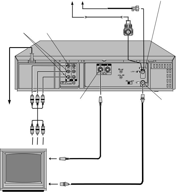
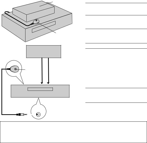
Basic Connections
|
|
Antenna or cable |
|
|
Coaxial cable |
|
|
Flat feeder |
|
|
Matching transformer |
AUDIO OUT |
VIDEO OUT |
(not supplied) |
|
||
AC Power |
|
Back of VCR |
|
|
|
Cord |
|
|
ANTENNA IN
(Antenna or cable input)
S VIDEO OUT
TV OUT
AC Outlet
Audio/video cable (supplied)
To Audio/video input connectors 

S-video cable (supplied)
To S-video input connector
RF cable (supplied)
To 75 Ω terminal
TV
|
|
|
|
EN 7 |
|
|
|
|
|
|
|
|
Check contents |
|
Final preparation for use |
|
|
1 Make sure the package contains all of the |
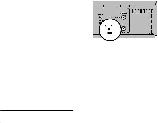
5 Turn on the VCR and set the CH3-CH4 switch on the |
||||
|
accessories listed in “SPECIFICATIONS” (Z pg. |
|
rear (shown below) to either CH3 or CH4 correctly. |
||
82). |
|
|
c The CH3–CH4 switch is preset to the CH3 |
||
|
|
|
|
position. |
|
|
Situate VCR |
|
Set to CH4 if CH3 is used for broadcasting in your |
||
2 Place the VCR on a stable, horizontal surface. |
|
area. (To view the picture from this VCR through |
|||
|
this channel, select the same channel on the TV |
||||
|
|
|
|
||
|
|
|
|
with the CH3–CH4 switch setting on the VCR.) |
|
|
Connect VCR to TV |
||||
|
|
c You can now perform basic playback (Z pg. |
|||
3 The following connections are required. |
|
||||
|
23) or basic recording (Z pg. 28). |
||||
|
|
|
|
|
|
|
RF Connection |
|
|
|
|
1 Disconnect the TV antenna from the TV.
2Connect the TV antenna cable to the ANTENNA IN terminal on the rear of the VCR.
3 Connect the supplied RF cable between the TV OUT terminal on the rear of the VCR and the TV’s antenna input terminal.
AV Connection |
(improves picture quality during |
|
|
|
|
|
|
|
|
||
tape playback.) |
|
|
|
|
|
|
|
|
|
||
|
|
|
|
|
|
|
|
||||
|
|
|
|
|
|
|
|
||||
If your TV is equipped with audio/video input |
|
|
|
|
|
|
|
|
|||
connectors |
|
|
|
|
|
|
Back of VCR |
||||
1 Connect the antenna, VCR and TV as shown in |
|
|
|
|
|
|
|||||
|
|
|
|
|
|
|
|
||||
the illustration. |
|
|
|
|
|
|
|
|
|||
2 Connect an audio/video cable between the |
|
|
|
|
|
|
|
|
|||
AUDIO/VIDEO OUT connectors on the rear of |
|
|
|
|
|
|
|
|
|||
the VCR and the audio/video input connectors |
|
|
|
|
|
|
|
|
|||
on the TV. |
NOTES: |
||||||||||
|
|
|
|||||||||
S-video Connection |
(allows you to make the |
||||||||||
c The VCR channel is the channel on which you can watch the |
|||||||||||
most of the S-VHS picture performance.) |
|||||||||||
picture from the VCR on the TV when only using the RF |
|||||||||||
|
|
|
|||||||||
If your TV is equipped with an S-video input |
connection. The VCR’s CH3-CH4 switch, on the back of the |
|
connector |
VCR, sets the VCR channel to CH3 or CH4. |
|
1 Perform “RF Connection” and “AV |
c Even if you are using audio/video cables to connect your VCR |
|
Connection” above. |
to your TV, you must also connect it using the RF cable. This |
|
2 Connect an S-video cable between the S VIDEO |
will ensure that you can record one show while watching |
|
another (Z pg. 31). |
||
OUT connector on the rear of the VCR and the |
||
c For full identification of the VCR’s rear panel, refer to the |
||
S-video input connector on the TV. |
||
Index ( Z pg. 80). |
||
|
4 Connect VCR to power source
Connect the AC power plug to an AC outlet.
cThe clock and tuner channels will automatically be set when the antenna is connected and when the AC power cord is first connected to an AC power outlet (Z pg. 8).
(If “Auto” or “CH” is displayed on the front display panel before the VCR is turned on, the clock and tuner channels are being set automatically. Wait until the clock time is displayed on the front display panel before turning on the VCR.)

8 EN |
INITIAL SETTINGS |
Plug & Play
Setting
Auto Clock Set/Auto Tuner Set
ATTENTION
cIf you use a cable box, Plug & Play will not function; set the clock and tuner channels separately. (Z pg.10 – 15)
cIt takes several minutes for the VCR to complete the Plug & Play setting.
cDo not press any buttons on the front panel or on the Remote while Plug & Play is in progress.
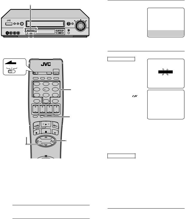
This VCR sets the clock and tuner channels automatically when AC power cord is first connected to an AC outlet. The antenna cable must be connected for the Plug & Play setting.
The time and date can be set automatically by the clock setting data transmitted from one of the regular TV broadcast channels. We call this TV channel the “host channel” and it is a PBS channel in your area.
1 Perform Plug & Play setup
Connect the antenna cable to the VCR (Z pg.
6). Then connect the AC power cord to an AC outlet. Do not turn on the VCR.
The clock and tuner channels will be set automatically.
NOTES:
cAuto Clock Set is performed first.
“Auto” blinks on the front display panel during Auto Clock Set.
cAuto Channel Set is performed next. Auto Channel Set scans all the channels that are receivable by your VCR. During Auto Channel Set, the channel numbers are displayed as they are scanned and set.
cWhen Plug & Play setting has been complete successfully, the correct clock time is displayed. If you perform Plug & Play setting successfully, there is no need to perform the clock (Z pg. 10) and tuner (Z pg.
13)settings. If, however, you want to add or delete channels, and use the ghost reduction function, refer to Manual Channel Set on pages 14 and 15.
|
|
|
|
|
|
|
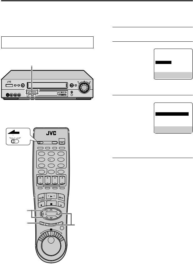
During Initial Auto Clock Set |
During Auto Channel Set |
|||||
The channel numbers are displayed |
||||||
“Auto” blinks. |
||||||
as they are scanned and set. |
||||||
|
|
|
||||
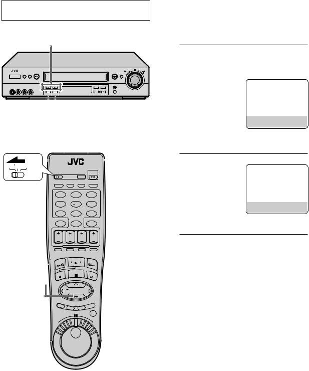
Plug & Play Completed
The current time (including AM/PM) is displayed.
*If an incorrect clock time or “– –:– –” appears on the display panel, see “What to do if Plug & Play setting failed” below.
INFORMATION
cIf “AUTO CLOCK” is set to “ON” on the Clock Set screen on page 11, the clock will be adjusted automatically by the host channel every hour (except 11:00 PM, midnight, 1:00 AM and 2:00 AM) using the incoming PBS channel clock setting data. (This automatic clock adjustment can only be performed when the VCR is turned off. The clock will be adjusted just on these hours — on the time displayed on the front display panel, not on the actual real time.)
The default setting of “AUTO CLOCK” is “ON”.
cIf the memory backup fails, because a power outage occurs or because the AC power cord is unplugged, Plug & Play will be performed when power is restored to the VCR.
cPoor antenna or cable signal may prevent the VCR from receiving the Auto clock setting data from the PBS channel. If this function is taking a considerable amount of time, it may be necessary to perform the Semiauto or Manual Clock Set procedure.
What to do if Plug & Play setting failed
cIf an incorrect time is displayed on the front display panel, you may be receiving the clock setting data of a PBS channel from an adjacent time zone, or an incorrect PBS channel from a cable TV system. In this case, perform the Semiauto (Z pg. 11) or Manual Clock Set (Z pg. 12) procedure.
cIf “- -:- -” appears on the front display panel, your antenna cable may not be connected to the VCR or there may not be a Host PBS signal available in your area. Ensure that the antenna cable is connected correctly. Then turn on and off the VCR; the Plug
& Play setting will be automatically reactivated.
If Plug & Play setting is not performed though the antenna cable is connected correctly, perform Manual Clock Set (Z pg. 12) and Auto Channel Set or Manual Channel Set (Z pg. 13 or 14).
EN 9
Language
Setting
Turn on the VCR and the TV, and select the VCR channel 3 or 4 (or AV mode) on the TV.
23
This VCR offers you the language choice to view menus and some messages — in English, Spanish or French. Select the desired language using the following procedure. The default setting is “ENGLISH”.
1 Access Main Menu screen
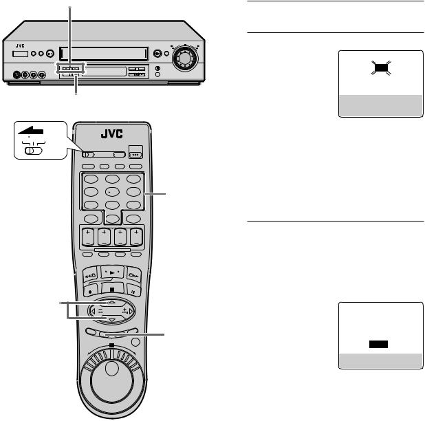
Press MENU.
2 Access Initial Set screen
On the front panel:
Press CH5° to move the highlight bar (arrow) to “INITIAL SET”, then press OK.
On the Remote:
Press %fito move the
highlight bar (arrow) to “INITIAL SET”, then press OK or #.
14
 23
23
VCR TV CABLE/DBS
1 2 3
4 5 6
7 8 9
0
3 Select language
On the front panel:
Press CH5° to move the highlight bar (arrow) to “LANGUAGE”, then press OK repeatedly until the desired language is selected.
INITIAL SET
CLOCK SET
=LANGUAGE ENGLISH
GUIDE CHANNEL SET
CABLE BOX SET
DBS RECEIVER SET
JLIP ID NO. SET
SELECT WITH (5,°) AND (OK)
PRESS (MENU) TO END
On the Remote:
Press %fito move the highlight bar (arrow) to “LANGUAGE”, then press OK or #repeatedly until the desired language is selected.
4 Return to normal screen
Press MENU.
23 |
|
14 |
23 |
10 EN |
INITIAL SETTINGS (cont.) |
Clock Setting
Turn on the VCR and the TV, and select the VCR channel 3 or 4 (or AV mode) on the TV.
2–7
18

 2–7
2–7
VCR TV CABLE/DBS
1 2 3
4 5 6
7 8 9
0
2–7

 2–7
2–7
18
 23
23
Perform clock setting only if the clock has not been set correctly by the Plug & Play setting or if you use a cable box.
Access the Clock Set screen to perform the Semiauto or Manual Clock Set. Each procedure starts from step 4 after preparation steps below are finished.
If you use a cable box, set the clock manually. (Z pg. 12)
Preparations
|
Access Main Menu screen |
||
1 Press MENU. |
|
|
|
|
Access Initial Set screen |
||
2 On the front panel: |
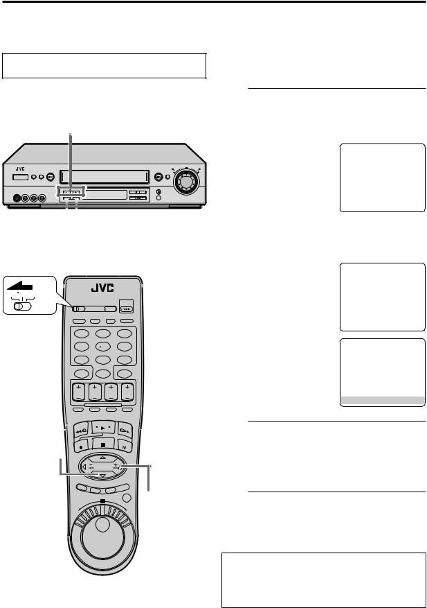
MAIN MENU |
||
|
Press CH5°to move |
FUNCTION SET |
|
|
the highlight bar (arrow) |
TUNER SET |
|
|
=INITIAL SET |
||
|
to “INITIAL SET”, then |
CTL |
|
|
REC LEVEL |
||
|
press OK. |
VIDEO NAVIGATION |
|
|
|
|
|
|
On the Remote: |
PRESS (5,°), THEN (OK) |
|
|
PRESS (MENU) TO END |
||
Press %fito move the
highlight bar (arrow) to “INITIAL SET”, then press OK or #.
Access Clock Set screen |
|
|||
3 On the front panel: |
INITIAL SET |
|||
Press CH5°to move |
|
|
|
|
=CLOCK SET |
ENGLISH |
|||
the highlight bar (arrow) |
LANGUAGE |
|
||
GUIDE CHANNEL SET |
||||
to “CLOCK SET”, then |
||||
CABLE BOX SET |
|
|||
press OK. |
DBS RECEIVER SET |
|||
JLIP ID NO. SET |
|
|||
On the Remote: |
SELECT WITH (5,°) AND (OK) |
|||
PRESS (MENU) TO END |
||||
Press %fito move the
highlight bar (arrow) to “CLOCK SET”, then press OK or #.
c“CABLE BOX USERS SET CLOCK MANUALLY” appears on the screen for about 5 seconds, then the Clock Set screen appears.
EN 11
Setting clock semiautomatically
— Semiauto Clock Set
You can change the host channel/D.S.T. /time zone setting manually.
First follow steps 1 to 3 on page 10, then go to the following steps.
Set Auto Clock to ON |
|
|
|
|
|
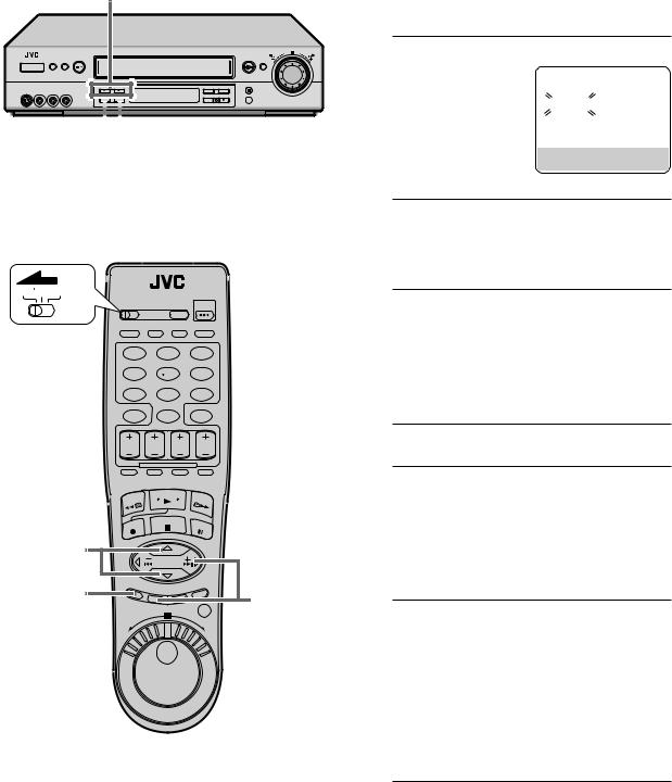
4 On the front panel: |
CLOCK SET |
|
|||
Press OK repeatedly to |
TIME |
DATE YEAR |
|||
move the highlight bar |
|||||
1:00PM |
12/24 |
|
00 SUN |
||
to “AUTO CLOCK”, |
AUTO CLOCK : ON |
|
|
||
HOST CH |
: AUTO |
(CATV) |
|||
then press CH5°so |
|||||
D.S.T. |
: AUTO |
|
|||
that “ON” is selected. |
TIME ZONE |
: AUTO |
|
||
PRESS (5,°), THEN (OK) |
|||||
PRESS (MENU) TO END
On the Remote:
Press #to move the highlight bar to “AUTO CLOCK”, then press %fiso that “ON” is selected. Then;
To select the host channel — go to step 5. To select the D.S.T. mode — go to step 6. To select the time zone — go to step 7.
NOTE:
The time set previously will be erased when “AUTO CLOCK”, “HOST CH”, “D.S.T.” or “TIME ZONE” setting is changed.
5 Select host channel
You can either select “AUTO” or enter a PBS channel number.
On the front panel:
Press OK to move the highlight bar to “HOST CH”, then press CH5°repeatedly until “AUTO” or the desired PBS channel number is selected.
On the Remote:
Press #to move the highlight bar to “HOST CH”, then press %fiuntil “AUTO” or the desired PBS channel number is selected.
NOTE:
Some PBS channels do not transmit clock setting data.
* Auto Daylight Saving Time
This function enables automatic adjustment of the VCR’s clock at the start and end of Daylight Saving Time.
With Auto DST activated, . . .
. . . |
on the first Sunday of April at 2:00 AM, the clock is |
adjusted to 3:00 AM. |
|
. . . |
on the last Sunday of October at 2:00 AM, the |
clock is adjusted to 1:00 AM.
6 Select D.S.T. mode
You have three choices:
AUTO– Select if you want to adjust your VCR’s clock automatically by the incoming signal from the host channel. (Auto Daylight Saving Time*)
ON– Adjustment will be made by the built-in clock itself.
OFF– Select when Daylight Saving Time does not apply to you.
On the front panel:
Press OK to move the highlight bar to “D.S.T.”, then press CH5°repeatedly until the desired setting is selected.
On the Remote:
Press #to move the highlight bar to “D.S.T.”, then press %firepeatedly until the desired setting is selected.
7 Select time zone
You can select the time zone automatically or manually.
On the front panel:
Press OK to move the highlight bar to “TIME ZONE”, then press CH5°repeatedly until “AUTO” or the desired time zone is selected. Each time you press the button, the time zone changes as follows:
OAUTO OATLANTIC OEASTERN
OCENTRAL OMOUNTAIN OPACIFIC
OALASKA OHAWAII O(back to the beginning)
On the Remote:
Press #to move the highlight bar to “TIME ZONE”, press %firepeatedly until “AUTO” or the desired time zone is selected (see above).
NOTE:
If an incorrect clock time is displayed by the Plug & Play setting, you may be receiving the clock setting data of a PBS channel from an adjacent time zone or from an incorrect PBS channel from a cable TV system. If you selected “AUTO” for the host channel in step 5, be sure to select the correct time zone manually.
8 Return to normal screen
Press MENU.
IMPORTANT
Turn off the VCR after performing Semiauto Clock Set. “Auto” will appear on the front display panel while the clock is being set. The current clock time will appear automatically when the clock setting is complete.
12 EN |
INITIAL SETTINGS (cont.) |
4–7
8
 4–6
4–6
VCR TV CABLE/DBS
1 2 3
4 5 6
7 8 9
0
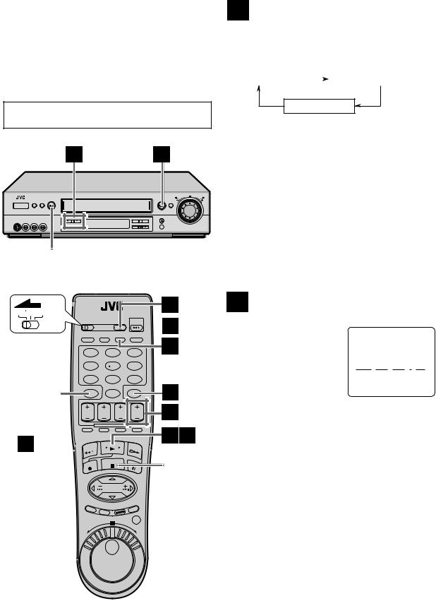
Setting clock manually
— Manual Clock Set
First follow steps 1 to 3 on page 10, then go to the following steps.
4 SetOn thetimefront panel:
Press CH5°until the desired time appears, then press OK.
On the Remote:
Press %fiuntil the desired time appears, then press OK or #.
CLOCK SET |
|
|
|
TIME |
DATE YEAR |
||
– –:– –AM |
1/ 1 |
00 |
|
AUTO CLOCK : ON |
|
|
|
HOST CH |
: AUTO |
(CATV) |
|
D.S.T. |
: AUTO |
|
|
TIME ZONE |
: AUTO |
|
|
PRESS (5,°), THEN (OK)
PRESS (MENU) TO END
cHolding CH 5°or %fichanges the time in 30-minute intervals.
cWhen the time is entered manually, “AUTO CLOCK” is automatically set to “OFF”, and “HOST CH” and “TIME ZONE” disappear.
5 SetOn thedatefront panel:
Press CH 5°until the desired date appears, then press OK.
On the Remote:
Press %fiuntil the desired date appears, then press OK or #.
cHolding CH 5°or %fichanges the date in 15day intervals.
6
4–7 |
|
|
8 |
4–6 |
7 |
|
Set year
On the front panel:
Press CH5°until the desired year appears, then press OK twice.
On the Remote:
Press %fiuntil the desired year appears, then press OK or #twice.
Select D.S.T. mode
You can select either “ON” or “OFF”.
ON– Adjustment will be made by the built-in clock itself.
OFF– Select when Daylight Saving Time does not apply to you.
On the front panel:
Press CH5°to select the desired setting.
On the Remote:
Press %fito select the desired setting.
8 StartPress MENUclock and normal screen appears.
To make corrections any time during the process
Press OK or #repeatedly until the item you want to change blinks, then press CH 5°or %fi.
EN 13
Tuner Setting
Turn on the VCR and the TV, and select the VCR channel 3 or 4 (or AV mode) on the TV.
23
14

 23
23
VCR TV CABLE/DBS
1 |
2 |
3 |
4 |
5 |
6 |
7 |
8 |
9 |
|
0 |
|
23
14
 23
23
Setting channels automatically
— Auto Channel Set
Use Auto Channel Set only if channels have not been set correctly by the Plug & Play setting. If you want to add or delete channels, and want to use the ghost reduction function, use Manual Channel Set (Z pg. 14).
|
Access Main Menu screen |
|
|
||||
1 Press MENU. |
|
|
|
|
|
|
|
|
Access Tuner Set screen |
|
|
||||
2 On the front panel: |
|
|
|
|
|
|
|
|
Press CH5° to move |
|
MAIN MENU |
|
|
||
|
|
|
|
|
|
|
|
|
the highlight bar (arrow) |
|
FUNCTION |
SET |
|
|
|
|
|
=TUNER SET |
|
|
|||
|
to “TUNER SET”, then |
|
|
|
|
|
|
|
|
INITIAL SET |
|
|
|
|
|
|
press OK. |
|
REC LEVEL CTL |
|
|
||
|
On the Remote: |
|
VIDEO NAVIGATION |
|
|
||
|
|
|
|
|
|
|
|
|
|
PRESS (5,°), THEN (OK) |
|
||||
|
Press %fito move the |
|
|
||||
|
|
PRESS (MENU) TO END |
|
|
|||
|
highlight bar (arrow) to |
|
|
|
|
|
|
|
“TUNER SET”, then press OK or #. |
|
|
||||
|
|
|
|
|
|
|
|
|
Perform Auto Channel Set |
|
|
||||
3 You can automatically |
|
|
|
|
|
|
|
|
set the receivable |
|
TUNER SET |
|
|
||
|
channels in your area in |
|
BAND |
CATV |
|||
|
the order of their |
|
=AUTO CHANNEL SET |
|
|
|
|
|
|
MANUAL CHANNEL SET |
|
|
|||
|
frequencies. |
|
|
|
|||
|
|
GHOST REDUCTION (GR) ON |
|||||
|
On the front panel: |
|
|
|
|
|
|
|
Press CH5° to move |
|
SELECT WITH (5,°) AND (OK) |
|
|||
|
the highlight bar (arrow) |
|
PRESS (MENU) TO END |
|
|
||
|
|
|
|
|
|
|
|
|
to “AUTO CHANNEL |
|
AUTO CHANNEL SET |
||||
|
SET”, then press OK. |
|
|
|
|
|
|
On the Remote:
SCANNING...
Press %fito move the highlight bar (arrow) to “AUTO CHANNEL
PRESS (MENU) TO END
SET”, then press OK or
#.
NOTES:
cWhen Auto Channel Set is complete, “SCAN COMPLETED” appears on screen.
cIf the scan was unsuccessful, “SCAN COMPLETED– NO SIGNAL” appears on screen. Check the connections and start again.
4 Return to normal screen
Press MENU.
INFORMATION
The VCR selects the correct band (TV or CATV) automatically during Auto Channel Set.
The selected band will be displayed on the right side of “BAND” on the Tuner Set screen.
14 EN |
INITIAL SETTINGS (cont.) |
2–4
15

 2–4
2–4
VCR TV CABLE/DBS
1 |
2 |
3 |
4 |
|
4 |
5 |
6 |
||
|
||||
7 |
8 |
9 |
|
|
|
0 |
|
|
|
|
|
|
4 |
2–4
15
 2–4
2–4
Setting channels manually
— Manual Channel Set
You can add the channels you want or delete the channels you do not want manually.
You can also select the ghost reduction mode for each channel while adding the channels you want.
1 Access Main Menu screen
Press MENU.
2 Access Tuner Set screen
On the front panel:
Press CH5°to move the highlight bar (arrow) to “TUNER SET”, then press OK.
On the Remote:
Press %fito move the highlight bar (arrow) to “TUNER SET”, then press OK or #.
Access Manual Channel Set screen |
|
|
3 On the front panel: |
TUNER SET |
|
Press CH5°to move |
BAND |
CATV |
the highlight bar (arrow) |
AUTO CHANNEL SET |
|
to “MANUAL |
=MANUAL CHANNEL SET |
ON |
GHOST REDUCTION (GR) |
||
CHANNEL SET”, then |
|
|
press OK. |
SELECT WITH (5,°) AND (OK) |
|
|
PRESS (MENU) TO END |
|
On the Remote:
Press %fito move the highlight bar (arrow) to “MANUAL CHANNEL SET”, then press OK or #.
4 Add or skip desired channels
To add channels
keys to input a
channel number you |
|
|
|
|
|||
PRESS NUMBER KEY (0–9) |
|||||||
want to add. |
|
OR (5,°), THEN (OK) |
|||||
2Press OK or #to set |
PRESS (MENU) TO END |
||||||
|
|
|
|
|
|||
to “ADD”. |
|
MANUAL CHANNEL SET |
|||||
3Press SP/EP ( |
) to |
|
|
(CATV) |
|||
select the desired |
|
|
CH |
45 ADD |
|
|
|
|
|
GR |
STANDARD |
|
|||
ghost reduction |
|
|
|
||||
|
|
|
|
|
|
||
mode if you want. |
PRESS NUMBER KEY (0–9) |
||||||
OR (5,°), THEN (OK) |
|||||||
(See also the next |
|||||||
GR MODE: PRESS (SP/EP) |
|||||||
page.) |
|
PRESS (MENU) TO END |
|||||
|
|
|
|
|
|
||
You have three choices: STANDARD – Normally select this.
SOFT – Select when you prefer softer picture than when “STANDARD” is selected.
OFF– Select when neither “STANDARD” nor “SOFT” improves the picture.
4Repeat 1 to 3 to add other channels. |
||
On the Remote ONLY: |
|
(CATV) |
1Press the Number |
CH |
45 ADD |
|
GR |
STANDARD |
To skip channels
On the front panel:
1Press CH5°to select a channel number you want to skip.
2Press OK to set to “SKIP”.
3Repeat 1 and 2 to skip other channels.
On the Remote:
1Press the Number keys or %fito input a channel number you want to skip.
2Press OK or #to set to “SKIP”.
3Repeat 1 and 2 to skip other channels.
5 Return to normal screen
Press MENU.
EN 15
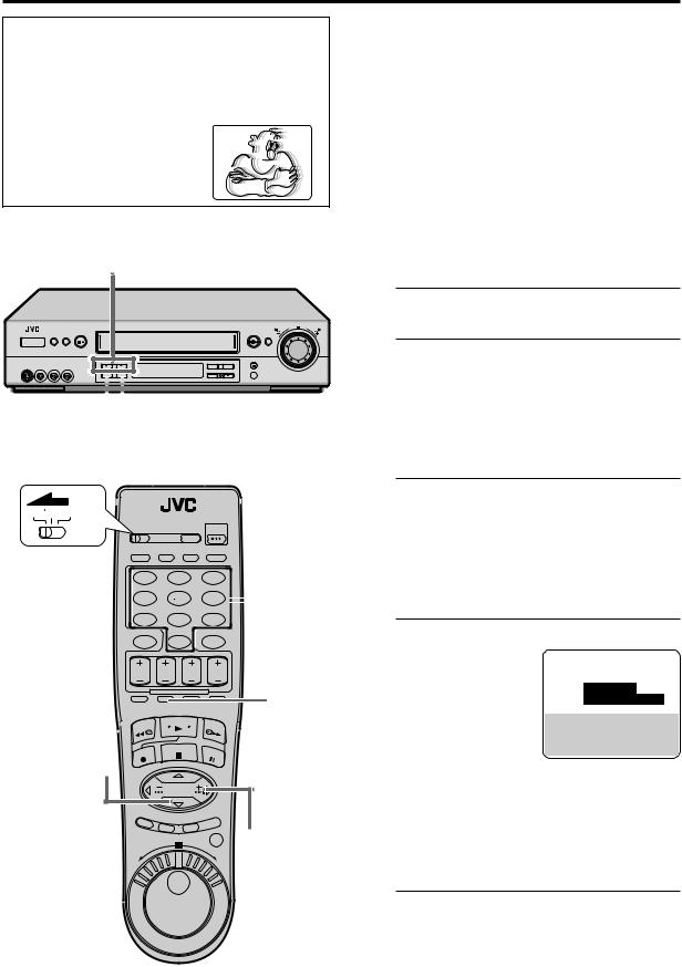
What is a “ghost”?
Double images of a TV program, or a “ghost”, is a common problem with TV reception in urban areas. A broadcasting signal, reflected from some surfaces (building, mountain, etc.), arrives slightly later than the signals arriving directly from the TV station. This causes such ghosts as follows:
– Double images
– Faint images
– Distorted images
–Distorted colors
–Vertically jittered images
2–3
15

 23
23
VCR TV CABLE/DBS
1 2 3
4 5 6  4
4
7 8 9
0
4
2–4
15
 23
23
Setting ghost reduction
This VCR is equipped with the ghost reduction function. It reduces the ghosts using a GCR (Ghost Canceller Reference) signal sent from a TV station. The ghost reduction mode can be set for each channel independently and manually.
NOTES:
cGhosts may not be reduced in the following cases:
–The broadcasting signal does not have a GCR signal.
–The antenna is not connected correctly.
–There are too many ghosts.
–The signal is reflecting from moving objects (airplane, etc.).
cThe images on the screen may be distorted when tuning from one channel to another or the power is turned on while the ghost reduction function is activated.
1 Access Main Menu screen
Press MENU.
2 Access Tuner Set screen
On the front panel:
Press CH5° to move the highlight bar (arrow) to “TUNER SET”, then press OK.
On the Remote:
Press %fito move the highlight bar (arrow) to “TUNER SET”, then press OK or #.
3 Access Manual Channel Set screen
On the front panel:
Press CH5° to move the highlight bar (arrow) to “MANUAL CHANNEL SET”, then press OK.
On the Remote:
Press %fito move the highlight bar (arrow) to “MANUAL CHANNEL SET”, then press OK or #.
4 Selectmode a channel and set ghost reduction
On the Remote ONLY:
(CATV)
1Press the Number CH 45 ADD
GR STANDARD
keys or %fito input a channel number.
2Press SP/EP (
 ) to select the desired ghost reduction mode. You have three choices:
STANDARD – Normally select this
SOFT – Select when you prefer softer picture than when “STANDARD” is selected.
OFF– Select when neither “STANDARD” nor “SOFT” improves the picture.
5 Return to normal screen
Press MENU.
16 EN |
INITIAL SETTINGS (cont.) |
Cable Box
Control
Setting
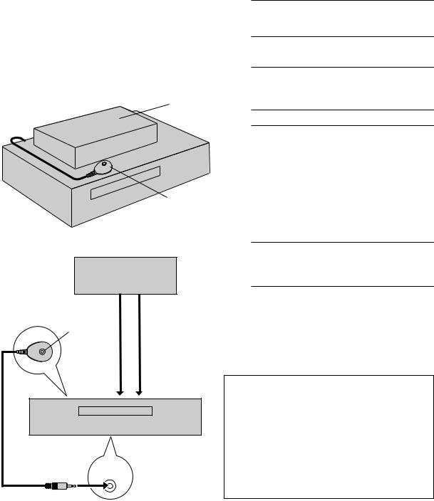
Suggested location
Place the cable box on top of the VCR. Attach the VCR’s Controller to the top of the VCR with the Controller’s transmitter pointed towards the cable box’s remote sensor.
ATTENTION:
The Controller can also control a DBS receiver. If both a cable box and a DBS receiver are used, position the Controller so its signal reaches the remote sensors on both the cable box and DBS receiver.
Your VCR
Cable box
To |
To |
RF output |
Audio/video |
Controller |
output |
Transmitter |
|
|
or |
To |
To |
ANTENNA |
AUDIO/ |
IN |
VIDEO IN |
Your VCR
CABLE
BOX
The following procedure is required if you receive your TV channels through a cable box (descrambler). The Controller allows the VCR to automatically switch the cable box channel during timer recording. The Controller is effective for recording broadcasts that have been programmed using VCR Plus+ (Z pg. 38) or Express timer programing (Z pg. 42).
Installing Controller
1 Situate Controller
Place the Controller so that its transmitter is facing the cable box’s remote sensor.
cMake sure the path between the Controller and the cable box’s remote sensor is not blocked.
2 Attach Controller
Fix securely using the adhesive strip attached on the back of the Controller.
3 Connect cable box to VCR
c If your cable box does not have audio/video output connectors
Connect the RF output terminal on the cable box to the ANTENNA IN terminal on the rear of your VCR.
cIf your cable box has audio/video output connectors
Connect an audio/video cable between the AUDIO/VIDEO IN connectors on the rear of the VCR and the audio/video output connectors on the cable box.
NOTE:
When connecting your cable box, refer to its instruction manual.
4 Connect Controller to VCR
Connect the Controller to the CABLE BOX Controller connector on the rear panel.
How to control the cable box
This VCR has two separate methods to control your cable box.
cThe VCR’s wireless Remote can control your cable box. This eliminates the need for a separate cable box’s Remote.
cThe VCR’s Controller can also control your cable box. This allows the VCR to change your cable box’s channel number during timer recording.
Each method must be set up separately. To set up the VCR’s Remote, refer to page 71. To set up the Controller, go to page 17.
EN 17
Turn on the VCR and the TV, and select the VCR channel 3 or 4 (or AV mode) on the TV.
34
2
 34
34
VCR TV CABLE/DBS
1 |
2 |
3 |
4 |
5 |
6 |
7 |
8 |
9 |
|
0 |
|
34
2
 34
34
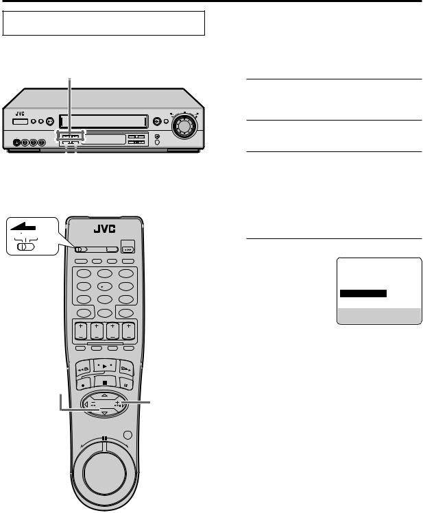
Setting cable box output channel & brand
After installation, set the cable box output’s channel and its brand correctly; otherwise, the Controller cannot work correctly.
1 Turn on cable box
Select a channel other than channel 9 on your cable box.
2 Access Main Menu screen on VCR
Press MENU.
3 Access Initial Set screen
On the front panel:
Press CH5° to move the highlight bar (arrow) to “INITIAL SET”, then press OK.
On the Remote:
Press %fito move the highlight bar (arrow) to “INITIAL SET”, then press OK or #.
4 Access Cable Box Set screen
On the front panel:
Press CH5° to move the highlight bar (arrow) to “CABLE BOX SET”, then press OK.
On the Remote:
Press %fito move the
highlight bar (arrow) to “CABLE BOX SET”, then press OK or #.
CONTINUED ON NEXT PAGE \

18 EN |
INITIAL SETTINGS (cont.) |
5 5

 67
67
VCR TV CABLE/DBS
1 2 3
4 5 6  7
7
7 8 9
0
6
7
5 |
67
Select cable box output channel
Your selection depends on how your cable box is connected to your VCR.
cIf your cable box is connected to your
VCR’s ANTENNA IN terminal on the rear
Press CH 5°on the front panel or %fion the Remote until the channel number representing the cable box’s output (CH2 – CH9) appears on the screen.
cIf your cable box is connected to your VCR’s AUDIO/VIDEO IN connectors on the front panel
Press CH 5°on the front panel or %fion the Remote until “ON F-1 (FRONT)” appears on the screen.
cIf your cable box is connected to your VCR’s AUDIO/VIDEO IN connectors on the rear panel
Press CH 5°on the front panel or %fion the Remote until “ON L-1 (REAR)” appears on the screen.
cIf you do not use a cable box
Press CH 5°on the front panel or %fion the Remote until “OFF” appears on the screen.
Access Cable Box Brand Set screen
Press OK.
Enter cable box brand
On the Remote ONLY:
Press the appropriate Number keys to enter the brand code from the list shown to the right, then press OK.
c If the cable box’s channel changes to 9, setting is complete
Press OK and “CABLE BOX CONTROL IS ON” appears on the screen for about 5 seconds, then it
returns to the normal screen.
cIf the cable box’s channel does not change to 9
1 Press %fi(or CH 5°on the front panel) to
move the highlight bar (arrow) to “NO”. 2 Press OK.
3 Repeat step 7 until the cable box’s channel changes to 9 by entering another code.
4If the channel does not change after going through all the code numbers listed for your model of cable box, then try all the other numbers.

EN 19
CABLE BOX BRAND LIST
BRAND |
CODE |
|
|
ARCHER |
1, 5, 17 |
CABLETENNA |
1, 17 |
CABLEVIEW |
15, 16, 17, 21, 25 |
CITIZEN |
15, 16, 17, 21, 25 |
CURTIS |
2, 8 |
DIAMOND |
1, 17 |
EASTERN |
19 |
GC BRAND |
15, 16, 17, 21, 25 |
GEMINI |
15 |
GENERAL INSTRUMENTS |
1, 4, 6, 11, 12, 15, 28 |
HAMLIN |
10, 18, 19, 23 |
JASCO |
15 |
JERROLD |
1, 4, 6, 11, 12, 15, 28 |
NOVAVISION |
2, 8 |
OAK |
7, 20 |
PANASONIC |
13, 14 |
PULSER |
15, 16, 17, 21, 25 |
RCA |
13, 14 |
REGAL |
10, 18, 19, 23 |
REGENCY |
19 |
REMBRANDT |
1, 16, 17 |
SAMSUNG |
5, 16, 24 |
SCIENTIFIC ATLANTA |
2, 8 |
SIGMA |
7, 20 |
SL MARX |
5, 16, 17, 24, 25 |
SPRUCER |
13, 14 |
STARGATE |
5, 15, 16, 17, 21, 24, 25 |
TELEVIEW |
5, 16, 24 |
TOCOM |
1, 4, 16 |
UNIKA |
1, 17 |
UNIVERSAL |
16, 17, 25 |
VIDEOWAY |
3, 9, 22 |
ZENITH |
3, 9, 22 |
|
|
If the VCR’s clock has not been set (with AUTO CLOCK set to ON)
“CABLE BOX USERS SET CLOCK MANUALLY” appears for about 5 seconds when you press OK in step 6, then the Clock Set screen appears.
Perform Manual Clock Set on page 12. If you press MENU after the clock has been set, the Cable Box Brand Set screen appears.
NOTES:
cThe Controller may not work with all types of cable box.
cIf your cable box does not respond to any code, you cannot use the Controller to change cable box channels. In this case, make sure to leave the cable box turned on and tuned to the proper channel before the scheduled start time of timer recording.
Contact your cable company about the possibility of exchanging your current cable box with the one compatible with your VCR.
cThe VCR can only change the cable box channel through the Controller during timer recording.
cIf your cable box cannot be operated with a remote control (because it has no remote sensor), you cannot use the Controller to change its channels. Make sure to leave the cable box turned on and tuned to the proper channel before the scheduled start time of timer recording.
cIf the VCR’s memory backup expires because of a power failure, set the cable box output channel and brand again.
cFor customers in U.S.A.: If you are unable to set the Controller, contact JVC toll free at 1-800-252-5722.
20 EN |
INITIAL SETTINGS (cont.) |
DBS Receiver
Control Setting
Suggested location
Place the DBS (Direct Broadcast Satellite) receiver on top of the VCR. Attach the VCR’s Controller to the top of the VCR with the Controller’s transmitter pointed towards the DBS receiver’s remote sensor.
ATTENTION:
The Controller can also control a cable box. If both a DBS receiver and a cable box are used, position the Controller so its signal reaches the remote sensors on both the DBS receiver and cable box.
DBS receiver
Controller
Your VCR (suggested
locations)
DBS receiver
Controller |
|
To |
To |
RF output |
Audio/Video |
Transmitter |
output |
or |
|
To |
To |
AUDIO/ |
|
ANTENNA IN |
VIDEO IN |
Your VCR
The following procedure is required if you receive satellite channels through a DBS (Direct Broadcast Satellite) receiver. The Controller allows the VCR to automatically switch the DBS receiver’s channels during timer recording.
NOTES:
cThe VCR can automatically change the DBS receiver channels using the Controller when the VCR has been programed using Express timer programing (Z pg. 42). Because satellite programing does not use PlusCode, the Controller cannot change the DBS receiver channels during VCR Plus+ timer recording.
(You can also use “Satellite Auto Recording” (Z pg. 61) if your DBS receiver is equipped with a timer.)
cIf a cable box is also used, it is recommended that you connect the DBS receiver to your VCR’s audio/video input connectors and the cable box to your VCR’s antenna input terminal.
Installing Controller
1 Situate Controller
Place the Controller so that its transmitter is facing the DBS receiver’s remote sensor.
cMake sure the path between the Controller and the DBS receiver’s remote sensor is not blocked.
2 Attach Controller
Fix securely using the adhesive strip attached on the back of the Controller.
3 Connect DBS receiver to VCR
c If your DBS receiver does not have audio/ video output connectors
Connect the RF output terminal on the DBS receiver to the ANTENNA IN terminal on the rear of your VCR.
c If your DBS receiver has audio/video output connectors
Connect an audio/video cable between the AUDIO/VIDEO IN connectors on the rear of the VCR and the audio/video output connectors on the DBS receiver.
NOTE:
When connecting your DBS receiver, refer to its instruction manual.
|
|
Connect Controller to VCR |
CABLE |
4 Connect the Controller to the CABLE BOX |
|
BOX |
Controller connector on the rear panel. |
|
|
|
|
How to control the DBS receiver
This VCR has two separate methods to control your DBS receiver.
cThe VCR’s wireless Remote can control your DBS receiver. This eliminates the need for a separate DBS receiver’s Remote.
cThe VCR’s Controller can also control your DBS receiver. This allows the VCR to change your DBS receiver’s channel number during timer-recording.
Each method must be set up separately. To set up the VCR’s Remote, refer to page 72. To set up the Controller, go to page 21.
EN 21
Turn on the VCR and the TV, and select the VCR channel 3 or 4 (or AV mode) on the TV.
3–5
2
 34
34
VCR TV CABLE/DBS
1 2 3
4 5 6
7 8 9
0
3–5
2
 34
34
Setting DBS receiver output channel & brand
After installation, set the DBS receiver’s output channel and its brand correctly; otherwise, the Controller cannot work correctly.
1 Turn on DBS receiver
Select a channel other than channel 55, 100 or 205 on your DBS receiver.
2 Access Main Menu screen on VCR
Press MENU.
3 Access Initial Set screen
On the front panel:
Press CH5° to move the highlight bar (arrow) to “INITIAL SET”, then press OK.
On the Remote:
Press %fito move the highlight bar (arrow) to “INITIAL SET”, then press OK or #.
4 Access DBS Receiver Set screen
On the front panel:
Press CH5° to move the highlight bar (arrow) to “DBS RECEIVER SET”, then press OK.
On the Remote:
Press %fito move the highlight bar (arrow) to
“DBS RECEIVER SET”, then press OK or #.
5 Select DBS receiver output channel
Your selection depends on how your DBS receiver is connected to your VCR.
c If your DBS receiver is connected to your
VCR’s ANTENNA IN terminal on the rear
Press CH 5° on the front panel or %fion the Remote until the channel number
representing the DBS receiver’s output (CH3 or CH4) appears on the screen.
cIf your DBS receiver is connected to your VCR’s AUDIO/VIDEO IN connectors on the front panel
Press CH 5° on the front panel or %fion the Remote until “ON F-1 (FRONT)” appears on the screen.
cIf your DBS receiver is connected to your VCR’s AUDIO/VIDEO IN connectors on the rear panel
Press CH 5° on the front panel or %fion the Remote until “ON L-1 (REAR)” appears on the screen.
cIf you do not use a DBS receiver
Press CH 5° on the front panel or %fion the Remote until “OFF” appears on the screen.
CONTINUED ON NEXT PAGE \
22 EN |
INITIAL SETTINGS (cont.) |
CH 5°
6OK
VCR TV CABLE/DBS
1 |
2 |
3 |
|
4 |
5 |
6 |
7 |
7 |
8 |
9 |
|
|
0 |
|
|
%
fi |
67
OK
NOTES:
cThe Controller may not work with all types of DBS receiver.
cIf your DBS receiver does not respond to the code, you cannot use the Controller to change satellite channels. In this case, make sure to leave the DBS receiver turned on and tuned to the proper channel before the scheduled start time of timer recording. In addition, if your DBS receiver is equipped with a timer, you can also use “Satellite Auto Recording” (Z pg. 61).
cThe VCR can only change the satellite channel through the Controller during timer recording.
cIf your DBS receiver cannot be operated with a remote control (because it has no remote sensor), you cannot use the Controller to change its channels. Make sure to leave the DBS receiver turned on and tuned to the proper channel before the scheduled start time of timer recording.
cFor customers in U.S.A.: If you are unable to set the Controller, contact JVC toll free at 1-800-252-5722.
6 AccessPress OKDBS. Receiver Brand Set screen
7 Enter DBS Receiver’s brand
On the Remote ONLY:
Press the appropriate Number keys to enter the brand code from the following list, then press OK.
The program currently received through the
DBS receiver appears for about 10 seconds.
BRAND |
CODE |
JVC (DISH Network) |
51 |
ECHOSTAR (DISH Network) |
51 |
PRIMESTAR |
50 |
SONY (DSS) |
41 |
RCA (DSS) |
40 |
|
|
cIf the DBS receiver’s channel changes to the channel listed below for your brand, setting is complete
JVC =100 ECHOSTAR =100 PRIMESTAR =55 SONY =205 RCA =205
Press OK and “DBS RECEIVER CONTROL IS ON” appears on the screen for about 5 seconds, then it returns to the normal screen.
cIf the DBS receiver’s channel does not change as shown above
1 Press %fi(or CH 5°on the front panel) to move the highlight bar (arrow) to “NO”.
2 Press OK.
3 Re-enter the correct code.

BASIC PLAYBACK AND RECORDING |
EN 23 |
Basic
Playback
Turn on the VCR and the TV, and select the VCR channel 3 or 4 (or AV mode) on the TV.
This VCR can check the tape condition during playback (and recording), and realizes the best possible pictures.
cWhen you play back a tape recorded on this VCR, you can use the Video Navigation function (Z pg. 46).
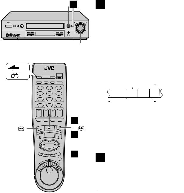
1 Load a cassette
Make sure the window side is up, the rear label side is facing you and the arrow on the front of the cassette is pointing towards the VCR.
Do not apply too much pressure when inserting.
POWER |
2 |
|
STOP/EJECT |
1 |
TIME SCAN |
2 |
|
SHUTTLE ring |
||||
( 7/ 0) |
VCR TV CABLE/DBS
 POWER
POWER
1 |
2 |
3 |
4 5 6
cThe VCR turns on automatically.
cThe counter is automatically reset to “0:00:00”.
cThe tape will run for a few seconds while the VCR searches for the tape number. If the tape number is found, it will be shown on the TV screen if “SUPERIMPOSE” is set to “ON.” (Z pg. 56, 57)
cIf the cassette’s record safety tab has been removed, playback begins automatically.
Start playback
Press PLAY ( 3).
cTape speed (SP or EP) is automatically detected.
cThe S-VHS indicator lights up when you play back a tape recorded in S-VHS mode or in S- VHS ET mode (Z pg. 31).
cIf “VIDEO CALIBRATION” is set to “ON” (default setting: Z pg. 57), “VIDEO CALIBRATION” appears on the screen, and this VCR checks the tape condition during automatic tracking.
7 8 9
0
2
REW ( 1) |
FF ( ¡) |
 STOP ( 7)
To stop playback
Press STOP ( 7 ) on the Remote or STOP/EJECT ( 7/ 0) on the front panel.
To rewind the tape (when it is not running)
Press REW ( 1) (or turn the TIME SCAN SHUTTLE ring on the front panel to the left).
To fast-forward (when it is not running)
Press FF ( ¡ ) (or turn the TIME SCAN SHUTTLE ring on the front panel to the right).
To eject the tape
Press STOP/EJECT ( 7/ 0) on the front panel when the tape is not running.
cYou can also eject the cassette when the VCR is turned off.
To turn off the VCR
Press POWER.
NOTE:
When you use the Video Navigation function, operate the VCR only after the tape number is detected; otherwise, you cannot use the Video Navigation function.
24 EN |
BASIC PLAYBACK AND RECORDING (cont.) |
Basic
Playback
Features
Turn on the VCR and the TV, and select the VCR channel 3 or 4 (or AV mode) on the TV.
D – 1– 3 |
C |
STOP/EJECT ( 7 / 0)
A Changing display information
Press DISPLAY during playback.
Each time you press the button, the front display panel shows the time counter, tape remaining time and the clock time in sequence.
Time Counter |
|
|
Tape Remaining Time |
|
|
||
|
|
|
|
Clock Time
cTo display the VCR status including the time counter and the clock time on the TV screen, see “Showing onscreen display” (Z pg. 31).
c“COUNT” appears on the screen when the time counter is shown. “REMAIN” appears on the screen when the tape remaining time is shown.
cWhen the tape remaining time appears, “ ” also lights on the front display panel.
cThe tape remaining time is calculated based on the tape speed (SP or EP) being used. The indicated remaining time is only an estimate.
To reset the time counter, press C. RESET on the Remote. The counter reading becomes “0:00:00”. It is also reset when a tape is inserted.
E
VCR TV CABLE/DBS
 F –b
F –b
1 |
2 |
3 |
A |
4 5
7 8
C. RESET |
0 |
F –a, b, c

6 |
9 |
F –C |
D –2 |
C F –a |
STOP ( 7 ) |
B Checking tape position
The tape position indicator |
|
|
|
|
appears on the screen in the |
|
|
|
|
following cases: |
|
|
|
|
c When you change the VCR |
|
|
|
|
operation mode from the |
|
+ + + |
|
|
stop mode to fast forward or |
B |
|
E |
|
|
||||
|
||||
rewind mode. |
|
|
|
|
c When you perform an Index |
|
COUNT |
0:33:27 |
|
Search (Z pg. 26) or Instant |
|
|
|
|
Review (Z pg. 26). |
|
|
|
|
The position of “  ” in relation to “B” (Beginning) or “E” (End) shows you where you are on the tape.
NOTES:
c“SUPERIMPOSE” must be set to “ON”, or the indicator will not appear (Z pg. 56, 57).
cIt may take a few seconds for the tape position indicator to be displayed.
EN 25
C Playing back tape repeatedly
— Repeat Play
You can play back a tape repeatedly (100 times).
While playing back a tape, press and hold PLAY ( 3) for more than 5 seconds.
The play indicator ( #) on the front display panel starts flashing slowly, and a tape will be played back 100 times.
To stop playback, press STOP ( 7) on the Remote or
STOP/EJECT ( 7/ 0 ) on the front panel.
D Adjusting tracking condition
— Tracking Adjustments
Automatic tracking adjustment
This VCR automatically adjusts the tracking condition. Whenever you insert a tape and start playback, automatic tracking starts working and continuously analyzes the signal to enable optimum picture quality during playback.
Manual tracking adjustment
If automatic tracking cannot eliminate noises well during playback, use the manual tracking following the procedures below.
cYou can also use the manual tracking during slow motion playback (Z pg. 36).
1 Activate manual tracking
Press CH 5and °on the front panel at the same time during playback.
2 Eliminate the noises on the TV screen.
Press CH 5and °(or CH + and – on the Remote).
cPress it briefly for a fine adjustment, or press and hold for a coarse adjustment. Watch the screen and continue adjustment until optimum picture and sound quality are achieved.
3 Reactivate automatic tracking
Press CH 5and °on the front panel at the same time. The automatic tracking becomes active again.
E Selecting monitor sound
— Audio Monitor
You can select the desired monitor sound.
While playing back a tape on which stereo sound or SAP sound is recorded, press A. MONITOR on the Remote.
Each time you press the button, sound changes as follows:
|
|
HI-FI |
|
|
|
HI-FI L |
|
|
HI-FI R |
|
|||||
|
|
|
|
|
|
|
|||||||||
|
|
|
|
|
|
|
|
|
|
|
|
|
|
|
|
|
|
|
NORM |
|
|
|
|
NORM |
|||||||
|
|
|
HI-FI |
|
|
|
|
|
|
|
|
|
|||
HI-FI: Normally select this.
Hi-Fi sound is played back.
HI-FI L: Sound on the left Hi-Fi channel is played back. HI-FI R: Sound on the right Hi-Fi channel is played back. NORM:Sound on the normal track is played back.
NORM HI-FI:
Both sounds on the Hi-Fi track and normal track are mixed and played back.
NOTES:
cThe above indication appears when “SUPERIMPOSE” is set to “ON” (Z pg. 56, 57), though the monitor sound changes in sequence.
cIf the tape being played back has no Hi-Fi sound track, the normal sound track will be heard regardless of this setting.
cIf RF connection (Z pg. 7) is used for viewing pictures on the TV, sound will be monaural even though you select “HI-FI”.
cYou can also use the menu to select your desired monitor sound. (Z pg. 59)
F Automatic operations after
rewinding — Next Function Memory
The Next Function Memory “tells” the VCR what to do after rewinding is complete.
c Ensure that the VCR is in stop mode.
a– For Automatic Playback Start
Press REW ( 1), then press PLAY ( 3) within 2 seconds.
b– For Automatic Power Off
Press REW ( 1), then press POWER within 2 seconds.
c– For Automatic Timer Standby
Press REW ( 1), then press TIMER within 2 seconds.
NOTE:
It is not possible to select the Automatic Timer Standby function if the cassette’s record safety tab is removed.
26 EN |
BASIC PLAYBACK AND RECORDING (cont.) |
J
PLAY ( 3) 
TIME SCAN
SHUTTLE ring
VCR TV CABLE/DBS
1 2 3
4 5 6
7 8 9
0
PLAY ( 3)


 I
I
REW ( ) |
FF ( ) |
 G
G

 H
H
G Locating beginning of
recordings — Index Search
Index codes are placed on the tape at the beginning of each recording when recording on this VCR. You can find and automatically play back from the beginning of any recording using the Index Search function.
1 Start search
While the tape is not running, press 4or ¢ on the Remote.
2 Access distant code
To access a recording of 2 to 9 index codes away, press 4or ¢repeatedly until the correct number is displayed on the screen (only if “SUPERIMPOSE” is set to “ON” ; Z pg. 56, 57). Playback begins automatically when the desired recording is located.
Beginning of the current |
|
|
|
Current position |
Beginning of the 2nd next |
||||||||
program recorded |
|
|
|
|
|
on the tape |
|
|
program recorded |
||||
|
|
|
|
|
|
||||||||
|
|
Previous |
|
|
|
|
|
|
Next |
|
|
|
|
|
|
program |
|
|
|
|
|
|
program |
2nd |
next |
||
|
|
recorded |
|
|
|
|
|
|
recorded |
|
|
|
|
|
|
–2 |
–1 |
|
|
|
1 |
|
2 |
|
3 |
||
|
|
|
4 |
|
¢ |
|
|
|
|
||||
|
|
|
|
|
|
|
|
||||||
|
|
|
|
|
|
|
|
|
|
|
|
|
|
|
|
|
|
|
|
|
|
|
|
|
|
|
|
cIf you want to find the very beginning of the
desired program, press REW (  ) or FF (
  ) on the Remote or turn the TIME SCAN SHUTTLE ring on the front panel after playback starts.
NOTE:
An index code is not placed on the tape when recording is resumed from recording pause.
H Locating beginning of timer
recordings — Instant Review
At the press of a button, you can turn on the VCR, rewind the tape and begin to view the most recent timerrecorded program.
Press REVIEW on the Remote after ensuring that the VCR is in the timer recording standby mode.
cThe VCR turns on, and rewinds to the index code indicating the beginning of the last timer-recorded program, then begins playback automatically.
cYou can access a program of 2 to 9 index codes away from the current position on the tape. If, for example, you have 5 programs recorded and you want to watch the third one, press REVIEW three times.
cIf you want to find the very beginning of the desired
program, press REW (  ) or FF (
  ) on the Remote or turn the TIME SCAN SHUTTLE ring on the front panel after playback starts.
cIf the tape is already rewound when REVIEW is pressed, it will play the tape from the beginning. It will not fast-forward to an index code.
cThe Instant Review function will also operate if the VCR is turned on.

EN 27
I Skipping unwanted portions
— Skip Search
You can skip over (view at high speed) unwanted portions of the tape.
Press SKIP SEARCH on the Remote once to 4 times during playback.
Each press initiates a 30-second period of high speed playback (up to 2 minutes). When the specified portion of the tape is skipped, normal playback resumes automatically.
To return to normal playback during Skip Search, press PLAY ( 3).
J Adjusting picture condition
— Digital TBC/NR
The Digital TBC/NR (Time Base Corrector / Noise Reduction) function removes jitter from fluctuating video signals to deliver a stable picture even with old tapes and rental tapes. The Digital R3 function which cuts noise and reproduces clear pictures is also linked to this function.
We recommend that you use the Digital TBC/NR function when...
—playing back a tape recorded on a camcorder.
—playing back a tape repeatedly used.
—using this VCR as the player for editing.
Press DIGITAL TBC/NR on the front panel so that the DIGITAL TBC/NR lamp lights up.
Each time you press the button, this function turns on and off.
NOTES:
cIf you play back a tape recorded under poor TV reception condition, the picture may happen to become more stable with Digital TBC/NR activated.
cIf you play back a tape on which certain types of signals (using a PC or some character generators) have been recorded with Digital TBC/NR activated, the playback picture may be distorted. In this case, deactivate Digital TBC/NR.
cDigital TBC/NR and Video Stabilizer (Z pg. 58) cannot be used at the same time; if you turn on Digital TBC/NR when “VIDEO STABILIZER” is set to “ON”, Video Stabilizer will be automatically turned “OFF”. Make sure Digital TBC/NR is deactivated when you want to use Video Stabilizer.
Other Useful functions for playback
You can also use the following functions for playback.
c Video Calibration (Z pg. 57)
When this function is set to “ON”, this VCR checks the condition of the tape in use during playback and recording, and compensates to provide the highestpossible pictures.
c Picture Control (Z pg. 57)
This function helps you to adjust the playback picture quality according to your preference.
c Digital R3 (Z pg. 58)
This function applies edge correction to the luminance signal to enhance details and provides clear pictures.
c Video Stabilizer (Z pg. 58)
You can automatically correct vertical vibrations in the picture when playing back unstable recordings made on another VCR.
Clean the video heads using a dry cleaning cassette — TCL-2UX — when:
•Rough, poor picture appears while a tape is played back.
•The picture is unclear or no picture appears.
•“USE CLEANING CASSETTE” appears on the screen (only with “SUPERIMPOSE” set to “ON”: Z pg. 56, 57.)
Loading...