


 Loading...
SERVICE MANUAL
VIDEO CASSETTE RECORDER
HR-S6950EU, HR-S6955MS,
HR-S7950EU, HR-S7955EK, HR-S7955MS
SPECIFICATIONS (The specifications shown pertain specifically to the model HR-S7950EU.)
GENERAL
Power requirement : AC 220 V – 240 Vd, 50 Hz/60 Hz Power consumption
Power on |
: 18 W |
Power off |
: 3.6 W |
Temperature |
: 5°C to 40°C |
Operating |
|
Storage |
: –20°C to 60°C |
Operating position |
: Horizontal only |
Dimensions (WxHxD) |
|
|
: 400 mm x 94 mm x 270 mm |
Weight |
: 3.4 kg |
Format |
: S-VHS/VHS PAL standard |
Maximum recording time |
|
(SP) |
: 240 min. with E-240 video cassette |
(LP) |
: 480 min. with E-240 video cassette |
(EP) |
: 720 min. with E-240 video cassette |
VIDEO/AUDIO
Input/Output |
: 21-pin SCART connectors: |
|
IN/OUT x 1, IN/DECODER x 1 |
|
RCA connectors: |
|
VIDEO IN x 1, AUDIO IN x 1, |
|
AUDIO OUT x 1 |
|
S-Video connector: |
|
IN x 1, OUT x 1 |
TUNER/TIMER
TV channel storage capacity
|
: 99 positions (+AUX position) |
Tuning system |
: Frequency synthesized tuner |
Channel coverage |
: VHF 47 MHz – 89 MHz/ |
|
104 MHz – 300 MHz/ |
|
302 MHz – 470 MHz |
|
UHF 470 MHz – 862 MHz |
Aerial output |
: UHF channels 22 – 69 (Adjustable) |
Memory backup time
: Approx. 10 min.
Signal system |
: PAL-type colour signal and CCIR |
|
monochrome signal, 625 lines |
|
50 fields |
Recording system |
: DA4 (Double Azimuth) head helical |
|
scan system |
Signal-to-noise ratio: 45 dB
Horizontal resolution
(SP/LP) |
: 250 lines (VHS) |
|
|
400 lines (S-VHS) |
|
(EP) |
: 220 lines (VHS) |
|
|
350 lines (S-VHS) |
|
Frequency range |
: 70 |
Hz to 10,000 Hz (Normal audio) |
|
20 |
Hz to 20,000 Hz (Hi-Fi audio) |
ACCESSORIES
Provided accessories
:RF cable,
Infrared remote control unit, “R6” battery x 2
Specifications shown are for SP mode unless otherwise specified.
E.& O.E. Design and specifications subject to change without notice.
V15S1/S2/S15
This service manual is printed on 100% recycled paper. COPYRIGHT © 2002 VICTOR COMPANY OF JAPAN, LTD
No.82923
June 2002
TABLE OF CONTENTS
Section Title Page Section Title Page
Important Safety Precautions
INSTRUCTIONS
1. DISASSEMBLY |
|
3.3.1 Servo circuit ............................................................................... |
3-4 |
|
1.1 Manually removing the cassette tape .............................................. |
1-1 |
3.3.1.1 Switching point ...................................................................... |
3-4 |
|
1.2 Removing the major parts ................................................................ |
1-2 |
3.3.1.2 Slow tracking preset .............................................................. |
3-5 |
|
1.2.1 How to read the procedure table ................................................ |
1-2 |
3.3.2 Video circuit ............................................................................... |
3-5 |
|
1.2.2 Disassembly procedure ............................................................. |
1-2 |
3.3.2.1 EE Y/PB Y(S-VHS/VHS)level ................................................ |
3-5 |
|
1.3 Emergency display function ............................................................. |
1-4 |
3.3.3 Audio circuit ................................................................................ |
3-5 |
|
1.3.1 Displaying the EMG information ................................................ |
1-4 |
3.3.3.1 Audio REC FM ...................................................................... |
3-5 |
|
1.3.2 Clearing the EMG history ........................................................... |
1-4 |
3.3.4 Syscon circuit(EU/EK MODEL) .................................................. |
3-6 |
|
1.3.3 Details of the OSD display in the EMG display mode ........................ |
1-5 |
3.3.4.1 Timer clock ............................................................................ |
3-6 |
|
1.3.4 EMG content description ............................................................ |
1-6 |
3.3.5 PAL/SECAM converter circuit(MS MODEL) ............................... |
3-6 |
|
1.3.5 EMG detail information<1> ........................................................ |
1-7 |
3.3.5.1 Colour difference level .......................................................... |
3-6 |
|
1.3.6 EMG detail information<2> ........................................................ |
1-8 |
3.3.5.2 SECAM burst position ........................................................... |
3-6 |
|
1.3.7 EMG detail information<3> ........................................................ |
1-8 |
4. CHARTS AND DIAGRAMS |
|
|
1.4 Service position ................................................................................ |
1-9 |
|
||
1.4.1 How to set the "Service position" ............................................... |
1-9 |
4.1 BOARD INTERCONNECTIONS ...................................................... |
4-3 |
|
1.5 Jig RCU mode .................................................................................. |
1-9 |
4.2 MAIN(VIDEO/N.AUDIO) SCHEMATIC DIAGRAM ........................... |
4-5 |
|
1.5.1 Setting the Jig RCU mode ......................................................... |
1-9 |
4.3 MAIN(ON SCREEN) SCHEMATIC DIAGRAM ................................ |
4-7 |
|
1.5.2 Setting the User RCU mode ...................................................... |
1-9 |
4.4 MAIN(SECAM) SCHEMATIC DIAGRAM [HR-S6950MS/S7955MS] ................. |
4-8 |
|
1.6 Mechanism service mode ................................................................ |
1-9 |
4.5 MAIN(FMA) SCHEMATIC DIAGRAM .............................................. |
4-9 |
|
1.6.1 How to set the "Mechanism service mode" ................................ |
1-9 |
4.6 MAIN(SYSCON) SCHEMATIC DIAGRAM ..................................... |
4-11 |
|
1.6.2 How to exit from the "Mechanism service mode" ....................... |
1-9 |
4.7 MAIN(SW.REG) SCHEMATIC DIAGRAM ..................................... |
4-13 |
|
1.7 Maintenance and inspection .......................................................... |
1-10 |
4.8 MAIN(TUNER) SCHEMATIC DIAGRAM ....................................... |
4-15 |
|
1.7.1 Cleaning ................................................................................... |
1-10 |
4.9 MAIN(FRONT) ,MINI FRONT, S-JACK AND ADV.JOG SCHEMATIC DIAGRAM ... |
4-17 |
|
1.7.2 Lubrication ............................................................................... |
1-10 |
4.10 |
MAIN(MAIN TERMINAL) SCHEMATIC DIAGRAM ......................... |
4-19 |
1.7.3 Suggested servicing schedule for main components ....................... |
1-10 |
4.11 2D DIGITAL SCHEMATIC DIAGRAM [HR-S6950EU/S6955MS/S7955MS] ................... |
4-21 |
|
1.8 Sevicing items related to video navigation ..................................... |
1-10 |
4.12 |
3D/TBC (2M) SCHEMATIC DIAGRAM [HR-S7950EU/S7955EK] .......................... |
4-23 |
2. MECHANISM |
|
4.13 TERMINAL(S-SUB) SCHEMATIC DIAGRAM ................................. |
4-25 |
|
|
4.14 TERMINAL(I/O) SCHEMATIC DIAGRAM ......................................... |
4-27 |
||
2.1. Before disassembling/assembling .................................................. |
2-1 |
4.15 |
DEMODULATOR SCHEMATIC DIAGRAM ..................................... |
4-29 |
2.1.1 Notes .......................................................................................... |
2-1 |
4.16 |
S-P CONVERTER SCHEMATIC DIAGRAM [HR-S6955MS/S7955MS] ............... |
4-31 |
2.1.2 Mechanism operation check ...................................................... |
2-1 |
4.17 |
MAIN CIRCUIT BOARD ............................................................... |
4-33 |
2.1.3 Setting the mechanism assembling mode ................................. |
2-1 |
4.18 |
2D DIGITAL AND 3D DIGITAL/2M CIRCUIT BOARDS ............... |
4-36 |
2.1.4 Layout of the main mechanism parts ......................................... |
2-2 |
4.19 |
DEMODULATOR CIRCUIT BOARD ............................................ |
4-37 |
2.1.5 Disassembling procedure table .................................................. |
2-3 |
4.20 |
S-P CONVERTER CIRCUIT BOARD[HR-S6955MS/S7955MS] ............ |
4-37 |
2.2. Replacement of the main mechanism parts .................................... |
2-4 |
4.21 |
TERMINAL CIRCUIT BOARD ................................................................. |
4-38 |
2.2.1 Cassette holder .......................................................................... |
2-4 |
4.22 |
WAVEFORMS ......................................................................................... |
4-39 |
2.2.2 A/C head .................................................................................... |
2-5 |
4.23 |
VOLTAGE CHARTS ................................................................................ |
4-41 |
2.2.3 Guide arm, pinch roller arm ....................................................... |
2-6 |
4.24 REMOTE CONTROLLER SCHEMATIC DIAGRAM ........................ |
4-43 |
|
2.2.4 Idler arm, idler gear 1/2 .............................................................. |
2-6 |
4.25 |
FDP GRID ASSIGNMENT AND ANODE CONNECTION ..................... |
4-43 |
2.2.5 Main brake(T), brake lever, tension arm,reel disk(S/T), Rec safety lever .................... |
2-6 |
4.26 |
CPU PIN FUNCTION ...................................................................... |
4-44 |
2.2.6 Press lever, control cam, capstan brake assembly,loading motor assembly .................... |
2-7 |
4.27 |
SYSTEM CONTROL BLOCK DIAGRAM ........................................... |
4-45 |
2.2.7 Capstan motor, load gear, control plate ..................................... |
2-8 |
4.28 |
VIDEO BLOCK DIAGRAM ............................................................... |
4-47 |
2.2.8 Clutch unit assembly, direct gear ............................................... |
2-9 |
4.29 AUDIO BLOCK DIAGRAM ............................................................... |
4-51 |
|
2.3. Mechanism timing chart ................................................................ |
2-10 |
5. PARTS LIST |
|
|
|
|
|
||
3. ADJUSTMENT |
|
3.1 Before adjustment ............................................................................ |
3-1 |
3.1.1 Precaution ................................................................................... |
3-1 |
3.1.2 Required test equipments .......................................................... |
3-1 |
3.1.3 Required adjustment tools ......................................................... |
3-1 |
3.1.4 Color(colour) bar signal, color(colour) bar pattern ..................... |
3-1 |
3.1.5 Switch settings ........................................................................... |
3-1 |
3.1.6 Manual tracking mode (Auto tracking ON/OFF) setting ....................... |
3-1 |
3.1.7 EVR sdjustment ................................................................................... |
3-2 |
3.2 Mechanism compatibility adjustment ............................................... |
3-2 |
3.2.1 Tension pole position ................................................................. |
3-3 |
3.2.2 FM waveform linearity ................................................................ |
3-3 |
3.2.3 Height and tilt of the A/C head ................................................... |
3-3 |
3.2.4 A/C head phase(X-value) ........................................................... |
3-4 |
3.3 Electrical Adjustment ........................................................................ |
3-4 |
5.1 PACKING AND ACCESSORY ASSEMBLY<M1> ............................ |
5-1 |
5.2 FINAL ASSEMBLY<M2> .................................................................. |
5-2 |
5.3 MECHANISM ASSEMBLY<M4> ...................................................... |
5-4 |
5.4 ELECTRICAL PARTS LIST .............................................................. |
5-6 |
MAIN BOARD ASSEMBLY<03> .......................................................... |
5-6 |
2D D BOARD ASSEMBLY<05>[HR-S6950EU/S6955MS/S7955MS] .......... |
5-14 |
3D D/2M BOARD ASSEMBLY<05>[HR-S7950EU/S7955EK] ....................... |
5-15 |
TERMINAL BOARD ASSEMBLY<06> ............................................... |
5-16 |
A/C HEAD BOARD ASSEMBLY<12> ............................................................ |
5-18 |
DEMOD BOARD ASSEMBLY<14> .................................................... |
5-18 |
MINI FRONT BOARD ASSEMBLY<28>[HR-S7955MS] ...................... |
5-18 |
S.JACK BOARD ASSEMBLY<36> .................................................... |
5-18 |
ADV.JOG BOARD ASSEMBLY<38> .................................................. |
5-18 |
LOADING MOTOR BOARD ASSEMBLY<55> ................................... |
5-19 |
S-P CONVERTER BOARD ASSEMBLY<87>[HR-S6955MS/S7955MS] ...... |
5-19 |
The following table lists the differing points between models HR-S6950EU, HR-S6955MS, HR-S7950EU, HR-S7955EK and HR-S7955MS.
MODEL |
HR-S6950EU |
HR-S6955MS |
HR-S7950EU |
HR-S7955EK |
HR-S7955MS |
|||||||||
ITEM |
||||||||||||||
|
|
|
|
|
|
|
|
|
|
|
|
|
||
POWER PLUG |
CEE |
|
|
|
|
|
|
3PIN |
CEE |
|||||
|
|
|
|
|
|
|||||||||
DIGITAL SLOW |
NOT USED |
|
|
|
USED |
|
|
|
NOT USED |
|||||
|
|
|
|
|
|
|||||||||
RETAKE |
NOT USED |
|
|
|
|
|
|
|
|
|
USED |
|||
|
|
|
|
|
|
|
|
|
||||||
ZERO FRAME EDIT |
NOT USED |
|
|
|
|
|
|
|
|
|
USED |
|||
|
|
|
|
|
|
|
|
|
||||||
INSERT / AUDIO DUBBING |
NOT USED |
|
|
|
|
|
|
|
|
|
USED |
|||
|
|
|
|
|
|
|
|
|
||||||
MESECAM |
USED(MANUAL) |
USED(PB ONLY) |
USED(MANUAL) |
NOT USED |
USED(PB ONLY) |
|||||||||
SECAM |
NOT USED |
USED |
NOT USED |
|
|
|
USED |
|||||||
|
|
|
||||||||||||
TBC |
NOT USED |
|
|
|
USED |
|
|
|
NOT USED |
|||||
|
|
|
|
|
|
|||||||||
REAR S OUT(4-pin) |
NOT USED |
|
|
|
USED |
|
|
|
|
|
|
|||
|
|
|
|
|
|
|
|
|
||||||
REMOTE PAUSE TERMINAL |
NOT USED |
|
|
|
USED |
|
|
|
|
|
|
|||
|
|
|
|
|
|
|
|
|
||||||
BROADCASTING STANDARD |
B/G, D/K |
L, B/G |
B/G, D/K |
|
I |
L, B/G |
||||||||
RF OUT |
USED |
NOT USED |
USED |
|
|
|
NOT USED |
|||||||
|
|
|
||||||||||||
VPS |
USED |
NOT USED |
USED |
NOT USED |
|
|
|
|||||||
|
|
|
||||||||||||
OSD LANGUAGE |
13 LANGUAGES |
FRENCH |
13 LANGUAGES |
ENGLISH |
FRENCH |
|||||||||
x1.5 PLAYBACK with AUDIO |
NOT USED |
|
|
|
USED |
|
|
|
NOT USED |
|||||
|
|
|
|
|
|
|||||||||
Notes: Mark  is same as left.

Important Safety Precautions
Prior to shipment from the factory, JVC products are strictly inspected to conform with the recognized product safety and electrical codes of the countries in which they are to be sold. However, in order to maintain such compliance, it is equally important to implement the following precautions when a set is being serviced.
v Precautions during Servicing
1.Locations requiring special caution are denoted by labels and inscriptions on the cabinet, chassis and certain parts of the product. When performing service, be sure to read and comply with these and other cautionary notices appearing in the operation and service manuals.
2.Parts identified by the  symbol and shaded (
 ) parts are critical for safety.
Replace only with specified part numbers.
Note: Parts in this category also include those specified to comply with X-ray emission standards for products using cathode ray tubes and those specified for compliance with various regulations regarding spurious radiation emission.
3.Fuse replacement caution notice.
Caution for continued protection against fire hazard. Replace only with same type and rated fuse(s) as specified.
4.Use specified internal wiring. Note especially:
1)Wires covered with PVC tubing
2)Double insulated wires
3)High voltage leads
5.Use specified insulating materials for hazardous live parts.
Note especially:
1) |
Insulation Tape |
3) |
Spacers |
5) Barrier |
2) |
PVC tubing |
4) |
Insulation sheets for transistors |
|
6.When replacing AC primary side components (transformers, power cords, noise blocking capacitors, etc.) wrap ends of wires securely about the terminals before soldering.
Fig.1
7.Observe that wires do not contact heat producing parts (heatsinks, oxide metal film resistors, fusible resistors, etc.)
8.Check that replaced wires do not contact sharp edged or pointed parts.
9.When a power cord has been replaced, check that 10-15 kg of force in any direction will not loosen it.
Power cord
Fig.2
10.Also check areas surrounding repaired locations.
11.Products using cathode ray tubes (CRTs)
In regard to such products, the cathode ray tubes themselves, the high voltage circuits, and related circuits are specified for compliance with recognized codes pertaining to X-ray emission. Consequently, when servicing these products, replace the cathode ray tubes and other parts with only the specified parts.
Under no circumstances attempt to modify these circuits. Unauthorized modification can increase the high voltage value and cause X-ray emission from the cathode ray tube.
12.Crimp type wire connector
In such cases as when replacing the power transformer in sets where the connections between the power cord and power transformer primary lead wires are performed using crimp type connectors, if replacing the connectors is unavoidable, in order to prevent safety hazards, perform carefully and precisely according to the following steps.
1)Connector part number : E03830-001
2)Required tool : Connector crimping tool of the proper type which will not damage insulated parts.
3)Replacement procedure
(1)Remove the old connector by cutting the wires at a point close to the connector.
Important : Do not reuse a connector (discard it).
cut close to connector
Fig.3
(2)Strip about 15 mm of the insulation from the ends of the wires. If the wires are stranded, twist the strands to avoid frayed conductors.
15 mm
Fig.4
(3)Align the lengths of the wires to be connected. Insert the wires fully into the connector.
Metal sleeve
Connector
Fig.5
(4)As shown in Fig.6, use the crimping tool to crimp the metal sleeve at the center position. Be sure to crimp fully to the complete closure of the tool.
25 |
Crimping tool |
1. |
|
2. |
|
0 |
|
5. |
|
5 |
|
Fig.6
(5) Check the four points noted in Fig.7.
Not easily pulled free |
Crimped at approx. center |
|
|
of metal sleeve |
|
|
|
|
|
|
Conductors extended |
Wire insulation recessed |
|
|
more than 4 mm |
|
|
Fig.7
1 |
S40888-01 |

v Safety Check after Servicing
Examine the area surrounding the repaired location for damage or deterioration. Observe that screws, parts and wires have been returned to original positions, Afterwards, perform the following tests and confirm the specified values in order to verify compliance with safety standards.
1.Insulation resistance test
Confirm the specified insulation resistance or greater between power cord plug prongs and externally exposed parts of the set (RF terminals, antenna terminals, video and audio input and output terminals, microphone jacks, earphone jacks, etc.). See table 1 below.
2.Dielectric strength test
Confirm specified dielectric strength or greater between power cord plug prongs and exposed accessible parts of the set (RF terminals, antenna terminals, video and audio input and output terminals, microphone jacks, earphone jacks, etc.). See table 1 below.
3.Clearance distance
When replacing primary circuit components, confirm specified clearance distance (d), (d’) between soldered terminals, and between terminals and surrounding metallic parts. See table 1 below.
Chassis
Fig. 8
d |
d' |
Power cord, |
primary wire |
4.Leakage current test
Confirm specified or lower leakage current between earth ground/power cord plug prongs and externally exposed accessible parts (RF terminals, antenna terminals, video and audio input and output terminals, microphone jacks, earphone jacks, etc.).
Measuring Method : (Power ON)
Insert load Z between earth ground/power cord plug prongs and externally exposed accessible parts. Use an AC voltmeter to measure across both terminals of load Z. See figure 9 and following table 2.
|
a |
b |
Externally |
Z |
c |
|
|
|
exposed |
V |
|
accessible part |
|
|
|
Fig. 9 |
|
5.Grounding (Class 1 model only)
Confirm specified or lower grounding impedance between earth pin in AC inlet and externally exposed accessible parts (Video in, Video out, Audio in, Audio out or Fixing screw etc.).
Measuring Method:
Connect milli ohm meter between earth pin in AC inlet and exposed accessible parts. See figure 10 and grounding specifications.
AC inlet |
Grounding Specifications |
|
Exposed accessible part |
Grounding Impedance (Z) |
|
|
Region |
|
|
USA & Canada |
Z ≤ 0.1 ohm |
Earth pin |
Europe & Australia |
Z ≤ 0.5 ohm |
Milli ohm meter
Fig. 10
AC Line Voltage |
Region |
|
Insulation Resistance (R) |
Dielectric Strength |
Clearance Distance (d), (d') |
||||||||||||
|
|
|
|
|
|
|
|
|
|
|
|
|
|
|
|||
100 V |
Japan |
|
R |
£ |
1 MΩ/500 V DC |
AC 1 kV 1 minute |
|
d, d' |
£ |
3 mm |
|||||||
100 to 240 V |
|
AC 1.5 kV 1 miute |
|
d, d' |
£ |
4 mm |
|||||||||||
|
|
|
|||||||||||||||
|
|
|
|
|
|
|
|
|
|
||||||||
|
|
|
|
|
|
|
|
|
|
|
|||||||
110 to 130 V |
USA & Canada |
|
1 MΩ |
³ |
R |
³ |
12 MΩ/500 V DC |
AC 1 kV 1 minute |
|
d, d' |
£ |
3.2 mm |
|||||
|
|
|
|
|
|||||||||||||
110 to 130 V |
|
|
|
|
|
|
|
|
|
AC 3 kV 1 minute |
d |
£ |
4 mm |
|
|||
Europe & Australia |
|
R |
£ 10 MΩ/500 V DC |
|
|
(Class 2) |
d' |
£ |
8 mm (Power cord) |
||||||||
200 to 240 V |
|
|
|
||||||||||||||
|
|
|
|
|
|
|
|
|
AC 1.5 kV 1 minute |
d' |
£ |
6 mm (Primary wire) |
|||||
|
|
|
|
|
|
|
|
|
|
|
|
(Class 1) |
|||||
|
|
|
|
|
|
|
|
|
|
|
|
|
|||||
|
|
Table 1 Specifications for each region |
|
|
|
|
|
|
|||||||||
|
|
|
|
|
|
|
|
|
|
|
|
|
|
||||
AC Line Voltage |
Region |
|
|
|
|
Load Z |
Leakage Current (i) |
|
|
|
a, b, c |
||||||
100 V |
Japan |
|
|
|
|
|
1 kΩ |
i |
≤ |
1 mA rms |
Exposed accessible parts |
||||||
|
|
|
|
|
|
|
|
|
|
|
|
|
|
|
|||
|
|
|
|
|
|
|
|
|
|
|
|
|
|
|
|
||
110 to 130 V |
USA & Canada |
|
0.15 F |
|
|
|
1.5 kΩ |
i |
≤ |
0.5 mA rms |
Exposed accessible parts |
||||||
|
|
|
|
||||||||||||||
|
|
|
|
|
|
|
|||||||||||
|
|
|
|
|
|
|
|
|
|
|
|
|
|
|
|
|
|
|
|
|
|
|
|
|
|
|
|
i |
≤ |
0.7 mA peak |
Antenna earth terminals |
||||
110 to 130 V |
Europe & Australia |
|
|
|
|
|
2 kΩ |
i |
≤ |
2 mA dc |
|||||||
220 to 240 V |
|
|
|
|
|
|
|
|
i |
≤ |
0.7 mA peak |
Other terminals |
|||||
|
|
|
|
|
|
|
|
|
|||||||||
|
|
|
|
|
|
|
50 kΩ |
i ≤ |
2 mA dc |
||||||||
|
|
|
|
|
|
|
|
|
|
|
|
||||||
Table 2 Leakage current specifications for each region
Note: These tables are unofficial and for reference only. Be sure to confirm the precise values for your particular country and locality.
2 |
S40888-01 |
|
SECTION 1
DISASSEMBLY
1.1 Manually removing the cassette tape
If you cannot remove the cassette tape which is loaded because of any electrical or mechanical failures, manually remove it by taking the following steps.
(1)Unplug the power cord plug from the power outlet.
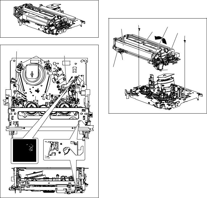
(2)Refer to the disassembly procedure of the VCR and perform the disassembly of the major parts before removing the mechanism assembly. (See Fig. 1-1a)
Fig. |
1-1a |
Tension arm assembly |
|
Pole base assembly Pinch roller arm assembly |
|
Spring(a) |
|
|
Direction of unloading |
Fig. |
1-1b |
(3)Unload the pole base assembly by manually turning the gear of the loading motor until the pole base assembly is hidden behind the cassette lid. In doing so, hold the tape by the hand to keep the slack away from any grease. (See Fig. 1-1b.)
In case of mechanical failures, while keeping the tension arm assembly free from tension, pull out the tape on the pole base assembly. Take the spring(a) of the pinch roller arm assembly off the hook, and detach it from the tape.
(4)Remove the screw (a) of the side frame (L/R).
(5)Hold the slack tape and cassette cover together, lift the cassette tape, top frame, cassette holder and side frames (L, R) together from the rear and remove them by disengaging the hooks (a) and (b).
Screw(a) |
Cassette holder |
||
Cassette tape |
|||
|
|
||
Top frame |
Side frame(R) |
||
|
|
Screw(a) |
|
Hook(a) |
|
|
|
Side frame(L) |
|
Hook(b) |
|
Fig. |
1-1c |
|
|
(6)Take up the slack of the tape into the cassette. This completes removal of the cassette tape.
1-1

1.2 Removing the major parts
1.2.1How to read the procedure table
This table shows the steps for disassembly of the externally furnished parts and board assemblies. Reverse these steps when re-assembling them.
<Example>
Step/ |
Part Name |
Fig. |
Point |
Note |
||||||
LocNo. |
No. |
|||||||||
|
|
|
|
|
|
|||||
[1] |
Top cover, |
1-3a |
4(S1a),(S1b),3(L1a), |
<Note 1a> |
||||||
|
|
|
|
|
|
2(SD1a),(P1a),(W1a), |
|
|
||
|
|
|
|
|
|
CN1(WR1a), |
|
|
||
|
|
Bracket |
|
|
---------------------------------------- |
|||||
|
|
|
|
2(S1c) |
|
|
||||
|
|
|
|
|
|
|
|
|
|
|
|
|
|
|
|
|
|
|
|
|
|
(1) |
(2) |
(3) |
(4) |
(5) |
||||||
(1)Order of steps in Procedure
When reassembling, perform the step(s) in the reverse order. These numbers are also used as the identification (location) No. of parts Figures.
(2)Part name to be removed or installed.
(3)Fig. No. showing procedure or part location.
(4)Identification of part to be removed, unhooked, unlocked, released, unplugged, unclamped or unsoldered.
P= Spring, W= Washer, S= Screw, L= Locking tab, SD= Solder, CN**(WR**)= Remove the wire (WR**) from the connector (CN**).
Note:
•The bracketed ( ) WR of the connector symbol are assigned nos. in priority order and do not correspond to those on the spare parts list.
(5) Adjustment information for installation
1.2.2 |
Disassembly procedure |
|
|
||
|
|
|
|
|
|
Step/ |
Part Name |
Fig. |
Point |
Note |
|
LocNo. |
No. |
||||
|
|
|
|||
[1] |
Top cover |
1-2-2d |
4(S1a), (S1b) |
|
|
|
|
|
|
|
|
[2] |
Front panel |
1-2-2d |
[HR-S7955MS] |
<Note 2a> |
|
|
assembly |
|
CN7005(WR2a) |
<Note 2b> |
|
|
|
|
-------------------------- |
|
|
|
|
|
[HR-S6950EU, S6950MS |
|
|
|
|
|
HR-S7950EU, S7955EK] |
|
|
|
|
|
CN7001(WR2a), |
|
|
|
|
|
-------------------------- |
|
|
|
|
|
CN916(WR2b), |
|
|
|
--------------------------- |
------- |
2(S2a), 4(L2a), 3(L2b) |
-------------- |
|
|
-------------------------- |
||||
|
[HR-S7955MS] |
|
CN7001(WR2c) |
|
|
|
Mini front board assembly |
|
(L2c), (L2d), |
|
|
|
--------------------------- |
------- |
PC Support |
-------------- |
|
|
-------------------------- |
||||
|
(ADV. Jog board assembly) |
|
2(S2b), Knob assembly |
|
|
|
--------------------------- |
------- |
-------------------------- |
-------------- |
|
|
(Front S jack board assembly) |
|
2(S2c) |
|
|
|
|
|
|
|
|
[3] |
Mechanism |
1-2-2d |
CN2001(WR3a), |
<Note 2a> |
|
|
assembly |
|
(S3a), (S3b) |
<Note 3a> |
|
|
(Drum assembly) |
|
-------------------------- |
<Note 3b> |
|
|
|
CN1(WR3b), |
|||
|
|
|
(S3c), (S3d), (S3e) |
<Note 3c> |
|
|
(Inertia plate) |
|
-------------------------- |
|
|
|
|
4(L3b) |
|
||
|
|
|
-------------------------- |
|
|
|
(Roller arm assembly) |
|
(S3g), (W3a), (P3a), |
|
|
|
|
|
(L3c) |
|
|
|
|
|
|
|
|
[4] |
[HR-S6955MS, S7955MS] |
1-2-2d |
CN511(WR4a) |
|
|
|
S/P Converter board assembly |
|
2(S4a), (L4a) |
|
|
|
|
|
|
|
|
[5] |
Main board assembly |
1-2-2d |
(S5a), 3(S5b), (L5a) |
|
|
|
|
|
|
|
|
[6] |
Bottom cover |
1-2-2d |
3(L6a), 5(L6b), 2(L6c) |
|
|
|
|
|
|
|
|
<Note 2a>
•Be careful not to damage the connector and wire etc. during connection and disconnection.
•When connecting the flat wire to the connector, be careful with the flat wire direction.
<Note 2b>
•When reattaching the Front panel assembly, make sure that the door opener of the Side frame (R) is lowered in position prior to the reinstallation.
•When reattaching the Front panel assembly, pay careful attention to the switch lever of the Front panel assembly not to make it touch the switch knob of the Main board assembly from the side.
•When reattaching the Front panel assembly, lift the Cassette door slightly.
Door |
|
|
opener |
|
|
Side |
Switch |
|
lever |
||
frame(R) |
||
Switch |
||
|
knob |
|
|
Fig. 1-2-2a |
<Note 3a>
•When reattaching the Mechanism assembly, secure the screws (S3a to S3b) in the order of a, b.
<Note 3b>
•When reattaching the Mechanism assembly, be sure to align the phase of the Rotary encoder on the Main board assembly.
•When reattaching the Mechanism assembly, set the “Mechanism assembling mode”. (See “section 2 mechanism”.)
•When reattaching the Mechanism assembly to the Main board assembly, take care not to damage the sensors and switch on the Main board assembly.
(S3c) (S3d)
 (S3e)
(S3e)
Mechanism assembly 
Drum  assembly <Note 3c>
(S3e)
(S3d)
HOOK
(S3c)
<NOTE>
Attach the Drum assembly appropriately,
since the installation state of the Drum assembly influences the FM WAVEFORM LINEARITY greatly.
Fig. 1-2-2b
<Note 3c>
•When reattaching the Drum assembly, secure the screws (S3c to S3e) in the order of c, d, e.
•When handling the drum assembly alone, hold it by the motor or shaft. Be careful not to touch other parts, especially the video heads. Also take care not to damage the connectors.
Shaft
Motor
Video heads
Fig. 1-2-2c
1-2

|
|
|
Drum assembly |
|
NOTE) INERTIA PLATE should be attached so as to ser small |
|
|||
diameter of central round hole above. |
|
(S3a) |
|
|
Inertia plate |
(S3g) |
|
<Note 3a> |
(S1a) |
(L3b) |
(S2a) |
|
||
(W3a) |
|
|
||
|
|
(WR3a) |
||
|
|
|
|
|
|
(P3a) |
|
g |
<Note 2a> |
Roller arm assembly |
|
|
|
|
|
|
|
|
|
<Note 3e> |
(L3c) |
|
d |
(S3b) |
|
|
|
<Note 3a> |
|
|
g |
|
|
|
NOTE) When attaching ROLLER ARM ASS'Y, |
|
|
||
attach the hook(L3c) before the spring(P3a). |
|
[3] Mechanism assembly |
||
|
|
|
|
|
NOTE) After attached ROLLER ARM ASS'Y, tighten screw(S3g) with slit washer(W3a).
(S5b)
(S4a)
(S5a) |
|
(S4a) |
|
|
03 |
|
Q30 |
k |
|
h |
|
[4] S/P conveter board |
a |
assembly |
|
e |
|
d |
<Note 3b> |
<Note 3c> |
a |
|
(S2a) |
|
|
||
(S3c) |
(S3e) |
|
|
c |
<Note 3c> |
|
|
|
|
|
|
|
(S3d) |
|
|
|
<Note 3c> |
|
|
|
c (S5b) |
|
Insert the bushing of POWER CORD |
|
|
|
so as not to twist the cord. |
d |
|
|
REAR SIDE |
b
c' |
|
|
e |
01 |
(S5b) |
|
[5]Main board |
D30 |
|
|
|
|
C |
N5001 |
assembly |
01 |
02 |
|
|
JS30 |
Q30 |
|
|
|
d' |
|
JS3001 |
|
c' |
|
[1] Top cover
(S1a)
(S1b)
h
ONLY USED FOR HR-S6955MS, HR-S7955MS
k |
|
(L5a) |
b |
<Phase alignment> |
|
|
|
h |
|
Accord the position of V gap on R. Encoder and PWB silk " |
". |
(L4a) a |
|
b |
|
Accord the position of Boss on R. Encoder and PWB silk " |
". |
f |
b |
|
|||
|
|
c' |
|
|
|
|
f |
Switch knob |
|
|
|
|
<Note 2b> |
|
|
|
|
h |
|
|
|
|
|
|
|
e |
|
|
|
|
|
d' |
|
For the prevention of the DRUM FPC damage. |
|
|
|
c' b |
|
|
|
|
"Z" |
(L6c) |
|
When you attach the Mechanism assembly on Bottom chassis. |
|
|
|
Attach the Mechanism assembly after the positioning boss "z" of the |
|
||
Bottom chassis is matched to the positioning hole of the Mehcanism assembly.
[2] Front panel |
|
|
b |
|
|
|
|
||
assembly |
ONLY USED |
|
||
<Note 2b> |
FOR HR-S7955MS |
|
||
|
|
(L2c) |
f |
|
|
(L2a) |
PC Support |
||
|
|
|||
|
(L2b) |
(L2d) |
|
|
|
|
|
||
|
|
[2]Mini front board |
|
|
|
|
assembly |
|
|
|
|
(L2a) |
|
|
|
|
(L6a) |
||
Cassette door |
|
f |
|
|
|
(L2b) |
|
||
<Note 2b> |
|
|
||
|
|
f |
|
|
Knob assembly |
|
|
||
|
|
[6] Bottom cover |
|
|
|
|
(L6b) |
|
|
|
|
|
(L6a) |
|
The excessive length portion |
(WR3b) |
back side |
||
<Note 2a> |
||||
|
||||
of wire should be reat as figure.
right side
CN1601
DRUM
A
(WR2b) <Note 2a>
To Front S Jack board assembly
NOTE) INSERT FFC WIRE TO THE CONNECTOR BEFORE
f |
ATTACHING JOG/SW PWB TO F.PANEL. |
|
|
||
NOTE)INSERT FFC WIRE TO THE CONNECTOR |
|
||||
|
BEFORE ATTACHING JOG/SW PWB TO F.PANEL. |
|
|||
Back side |
NOTE) WHEN YOU FIX FRONT S Jack PWB WITH THE SCREW. |
||||
|
PUT JIG UNDER FRONT PANEL ASS'Y. |
|
|||
|
|
|
|
||
ADV. Jog board |
|
(WR2a) |
|
Front S Jack board assembly |
|
|
<Note 2a> |
Front panel assembly back side |
|
||
assembly |
|
|
|
||
|
|
|
|
|
|
|
CN7003 |
|
|
|
|
(L6b) |
|
|
|
CN7108 |
|
|
|
|
|
|
|
(L6a) |
|
|
|
|
(WR2b) |
|
|
|
Switch lever |
|
|
|
(S2b) |
|
(S2c) |
<Note 2a> |
|
|
|
<Note 2b> |
|
||
f |
|
|
|
|
|
f |
|
|
|
NOTE |
|
|
|
|
|
|
|
|
|
|
1. Insert direction of FFC WIRE as follows. |
||
(WR4a) <Note 2a> |
|
|
Right side Back side |
||
back side |
|
|
|
||
Make a crease |
|
|
|
|
|
Make a crease |
|
|
|
|
|
CN916 |
CN511 |
CN5001
CN2001
(WR3a) <Note 2a>
A/C HEAD
CN7001
 B
B
right side
 (WR2a)
To Adv. Jog board assembly <Note 2a>
electrode side |
supporting side |
2.FFC WIRE and DRUM FPC WIRE should be insert as follows.
OK |
NG |
|
90° |
|
|
CN |
CN |
CN |
3. Insert direction of POWER CORD. |
|
|
U/U(C)/JPN |
Except U/U(C)/JPN |
|
WHITE LINE |
BLUE |
|
|
|
|
NEUTRAL |
NEUTRAL |
|
|
|
|
|
CN5001 |
CN5001 |
|
ONLY USED |
|
|
FOR HR-S7955MS |
|
DETAIL "A" |
DETAIL "B" |
|
(WR2c)
Make a crease |
FRONT PANEL |


 CN7002 P/S CONV PWB
CN7005
About 5cm
(WR2a)
CN7001
Make a crease Push the FFC wire from the FRONT PANEL to rear side.
Fig. 1-2-2d
1-3
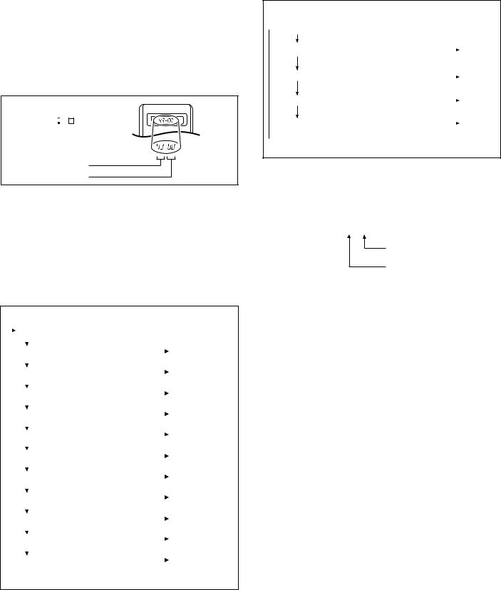
1.3 Emergency display function
This unit saves details of the last two emergencies as the EMG history and allows the status of the VCR and the mechanism of each emergency to be shown both on the display and as OSD information.
When using the emergency function, it is required to set the VCR to the Jig RCU mode (the mode in which codes from the Jig RCU can be received).
Jig RCU
[Data transmitting method] Depress the “ ” ( 3 ) button after the data code is set.
INITIAL MODE
CUSTOM CODE 43: A CODE
DATA CODE
Fig. 1-3a Jig RCU [PTU94023B]
1.3.1 Displaying the EMG information
The EMG detail of information can be displayed by transmitting the code "59" from the Jig RCU.
Note:
•The EMG detail information <1><2> show the information on the latest EMG.
It becomes “ – – : – – : – –” when there is no latest EMG record.
|
0: 00 |
Normal display |
|
|
|
|
|
|
|||
|
|
|
|
|
|
|
E: ** |
EMG content display (Latest) |
|
See 1.3.4. |
|
|
|
||||
|
|
|
|
|
|
|
1E: ** |
EMG content display (Previous) |
|
See 1.3.4. |
|
|
|
||||
|
|
|
|
|
|
1: *1 |
EMG detail information <1> |
|
See 1.3.5. |
||
|
|||||
|
|
|
[Deck operation mode] |
|
|
2: *2 |
EMG detail information <1> |
|
See 1.3.5. |
||
|
|||||
|
|
|
[Mechanism operation mode] |
|
|
3: 34 |
EMG detail information <1> |
|
See 1.3.5. |
||
|
|||||
|
|
|
[Mechanism sensor information and Mechanism mode position] |
||
4: *5 |
EMG detail information <2> |
|
See 1.3.6. |
||
|
|||||
|
|
|
[Type of the cassette tape in use <1>] |
||
5: *6 |
EMG detail information <2> |
|
See 1.3.6. |
||
|
|||||
|
|
|
[Winding position of the cassette tape in use] |
||
6: *7 |
EMG detail information <2> |
|
See 1.3.6. |
||
|
|||||
|
|
|
[Type of the cassette tape in use <2> (Winding area)] |
||
7: *8 |
EMG detail information <3> |
|
See 1.3.7. |
||
|
|||||
|
|
|
[Previous deck operation mode] |
|
|
8: *9 |
EMG detail information <3> |
|
See 1.3.7. |
||
|
|||||
|
|
|
[The deck operation mode of the one before the last] |
||
9: *10 |
EMG detail information <3> |
|
See 1.3.7. |
||
|
|||||
|
|
|
[The deck operation mode of the one prior to one above] |
||
|
|
|
|||
Fig. 1-3-1a EMG display of 7segment LED display model
 0 : 00 : 00
E: * * : * *
*1: *2 : 34
*5: *6 : *7
Normal display (Counter or clock) |
|
|
|
EMG content display (E:Latest:Previous) |
|
See 1.3.4. |
|
|
|||
[EMG code display mode] |
|
|
|
EMG detail information <1> display |
|
|
See 1.3.5. |
|
|
||
[Deck and other mode display mode] |
|
|
|
EMG detail information <2> display |
|
|
See 1.3.6. |
|
|
||
[Cassette display mode] |
|
|
|
*8: *9 : *10 EMG detail information <3> display |
|
See 1.3.7. |
|
|
|||
|
[Deck mode history dispaly mode] |
|
|
|
|
|
|
|
|
|
|
Fig. 1-3-1b EMG display of FDP display model
<Reference> EMG display of FDP display mode
(1)Transmit the code “59” from the Jig RCU.
The FDP shows the EMG content in the form of “E: * * : * * ”.
<Example 1> E : 01 : 03
Previous EMG
Latest EMG
<Example 2> E : – – : – –  No EMG record
(2)Transmit the code “59” from the Jig RCU again.
The FDP shows the EMG detail information <1> in the form of “ * 1 : * 2 : 34 ”.
*1 : Deck operation mode at the moment of EMG
*2 : Mechanism operation mode at the moment of EMG 3– : Mechanism sensor information at the moment of
EMG
–4 : Mechanism mode position at the moment of EMG
(3)Transmit the code “59” from the Jig RCU once again.
The FDP shows the EMG detail information <2> in the form of “ * 5 : * 6 : * 7 ”.
*5 : Type of the cassette tape in use <1> .
*6 : Winding position of the cassette tape in use
*7 : Type of the cassette tape in use <2> (Winding area)
(4)Transmit the code “59” from the Jig RCU once again.
The FDP shows the EMG detail information <3> in the form of “*8 : *9 : *10”.
*8 : Previous deck operation mode at the moment of EMG
*9 : The deck operation mode of the one before the last at the moment of EMG
*10 : The deck operation mode of the one prior to one above at the moment of EMG
(5)Transmit the code “59” from the Jig RCU once again to reset the display.
1.3.2Clearing the EMG history
(1)Display the EMG history.
(2)Transmit the code “36” from the Jig RCU.
(3)Reset the EMG display.
1-4
1.3.3 Details of the OSD display in the EMG display mode
During the EMG display, the OSD shows the data on the deck mode, etc. The details of the display contents are as follows.
Notes:
•The display is variable depending on the part No. of the System Control microcomputer (IC3001) built into the VCR. In the following, refer to the figure carrying the same two characters as the top two characters of the part
number of your IC.
•The sensor information in the OSD display contents is partially different from the mechanism sensor information in EMG detail information <1>.
[For MN* only]
AA |
BB |
CC |
DD |
EE |
FF |
GG |
HH |
I I |
J J |
KK |
L L |
MM |
NN |
OO |
PP |
RR |
SS |
TT |
|
UU |
VV |
WW |
XX |
YY |
A A : Deck operation mode (See EMG detail information <1>.)
B B : Mechanism operation mode (See EMG detail of information <1>.) C C : Mechanism transition flag
D D : Capstan motor control status E E : Loading motor control status
F F : Sensor information (See sensor information details.)
GG: Capstan motor speed
HH: Key code (JVC code)
II : Supply reel winding diameter data, higher 8 bits.
JJ : Supply reel winding diameter data, lower 8 bits.
KK : Mechanism sensor information & mechanism mode position (See EMG detail of information <1>.)
L L : Tape speed data, higher 8 bits. MM : Tape speed data, lower 8 bits.
N N : Cassette tape type <2>, higher 8 bits. (See EMG detail of information <2>.)
OO: Cassette tape type <2>, lower 8 bits. (See EMG detail of information <2>.)
P P : General data display area
Y Y : General data display area
*FF: Sensor information details
<Display> ** h
* |
* |
* |
* |
* |
* |
* |
* |
|
|
|
|
|
|
|
|
|
|
|
|
|
|
|
|
Encoder data
(See Mechanism mode sequence.)
Cassette tab present = 1
Cassette tab broken = 0
Cassette absent = 1
Cassette present = 0
Start sensor
End sensor
[For *HD only]
AA |
BB |
CC |
DD |
EE |
FF |
GGGG |
HHHH |
|
I I |
J J J J |
|
KKKK |
L L L L |
MMMM |
ROM No. |
|
|
A A : Key code (JVC code)
B B : Deck operation mode (See EMG detail information <1>.) C C : Mechanism operation mode (See EMG detail information <1>.) D D : Sensor information (See sensor information details.)
E E : Capstan motor speed (Search, double speed) F F : Tracking value
G G G G: Cassette tape type <2>, 16 bits. (See EMG detail information <2>.)
H H H H : Supply reel winding diameter data
I I : Capstan motor speed (FF/REW, double speed) J J J J : Tape speed data, lower 8 bits.
K K K K : General data display area L L L L : General data display area MMMM : General data display area
*DD: Sensor information details
<Display> ** h
* |
* |
* |
* |
* |
* |
* |
* |
|
|
|
|
|
|
|
|
|
|
|
|
|
|
|
|
Encoder data
(See Mechanism mode sequence.) Remote pause
End sensor Start sensor
Cassette tab present = 1 Cassette tab broken = 0
[For both MN*/HD*]
Mechanism mode sequence
Mechanism mode - Encoder data
1 |
2 |
3 |
4 |
5 |
6 |
7 |
8 |
9 |
10 |
11 |
LSA
LSB
LSC
LSD
|
Encoder output = Low |
|
|
|
Encoder output = High |
|
|
|
|||
|
or |
|
|
|
|
or |
|
|
|
|
|
|
Trerminal - GND = SHORT |
|
|
|
Trerminal - GND = OPEN |
|
|
|
|||
|
|
|
|
|
|
|
LSD LSC LSB LSA GND |
||||
No. |
Position |
|
Encoder data |
|
|||||||
1 |
EJECT |
|
0 h = 0000 |
|
5 |
4 |
3 |
2 |
1 |
||
2 |
EJECT1 |
|
1 h = 0001 |
|
|
|
|
|
|
||
3 |
EJECT2 |
|
2 h = 0010 |
|
|
|
|
|
|
||
4 |
ULSTOP |
|
3 h = 0011 |
|
|
|
|
|
|
||
5 |
UPPER |
|
4 h = 0100 |
|
|
|
|
|
|
||
6 |
ONSTOP(PLAY) |
|
5 h = 0101 |
|
|
|
|
|
|
||
7 |
FWD/SS |
|
6 h = 0110 |
|
|
|
|
|
|
||
8 |
REV/SS |
|
7 h = 0111 |
|
|
|
|
|
|
||
9 |
OFFSTOP |
|
8 h = 1000 |
|
|
|
|
|
|
||
10 |
FFREW-BRAKE |
|
9 h = 1001 |
|
|
|
|
|
|
||
11 |
FFREW |
|
A h = 1010 |
|
|
|
|
|
|
||
12 |
MIDDLE |
|
F h = 1111 |
|
|
|
|
|
|
||
1-5
Loading...