


 Loading...
SERVICE MANUAL
REAR PROJECTION TELEVISION
HV-44PRO, HV-44PRO/-A
HV-44PRO/EE , HV-44PRO/M
TABLE OF CONTENTS
1 PRECAUTION 1-3
2 SPECIFIC SERVICE INSTRUCTIONS 1-4
3 DISASSEMBLY 1-6
4 ADJUSTMENT 1-7
5 TROUBLE SHOOTING 1-21
COPYRIGHT © 2003 VICTOR COMPANY OF JAPAN, LTD. |
No. 52118 |
|
2003/11 |
|
|
|
SPECIFICATION |
|
|
|
|
Item |
|
Content |
|
|
|
|
|
Dimensions(W x H x D) |
|
95.4cm × 122.3cm × 55.1cm |
|
Mass |
|
50.0kg |
|
TV RF System |
|
CCIR B/G, I, D/K,M |
|
Colour System |
|
PAL / SECAM / NTSC3.58 / NTSC4.43 |
|
Sound System |
|
A2(B/G), NICAM(B/G,I,D/K) |
|
Teletext System |
|
Fastext(united kingdom system) , WST(world standard system) |
|
Receiving |
|
VHF |
47MHz ~ 470MHz |
Frequency |
|
UHF |
470MHz ~ 862MHz |
|
|
||
|
|
CATV |
116MHz ~ 172MHz / 220MHz ~ 469MHz |
Intermediate |
|
VIF |
38.9MHz(B/G,D/K,I) / 45.75MHz(M) |
Frequency |
|
SIF |
33.4MHz(5.5MHz : B/G) / 32.9MHz(6.0MHz : I) |
|
|
|
32.4MHz(6.5MHz : D/K) / 41.25MHz(4.5MHz : M) |
Colour Sub Carrier |
|
PAL |
4.43MHz |
Frequency |
|
SECAM |
4.40625MHz / 4.25MHz |
|
|
||
|
|
NTSC |
3.58MHz / 4.43MHz |
|
|
|
|
Power Input |
|
AC110V ~ AC240V, 50 / 60Hz |
|
Power Consumption |
|
250W(maximum) |
|
Screen Size |
|
Visible area : 112cm(measured diagonally), W : 97.6cm / H : 54.9cm |
|
High voltage |
|
21.3kV±0.1kV (at zero beam current) |
|
Audio Output |
|
20W + 20W(Rated) |
|
Antenna Input |
|
75Ω Unbalanced, coaxial |
|
External Input |
|
S-Video |
Mini-DIN-4 pin connector ×2 |
|
|
Y : 1V(p-p), positive(negative sync provided),75Ω |
|
|
|
|
|
|
|
|
C : 0.286V(p-p),(burst signal),75Ω |
|
|
Video |
RCA pin jack ×3 |
|
|
|
1V(p-p), negative sync, 75Ω |
|
|
Audio(L/R) |
RCA pin jack ×10 |
|
|
|
500mV(rms) (-4dBs), High impedance |
|
|
Component Video |
RCA pin jack ×6 |
|
|
|
Y : 1V(p-p), positive(negative sync provided), 75Ω |
|
|
|
PB : 0.7V(p-p), positive(negative sync provided), 75Ω |
|
|
|
PR : 0.7V(p-p), positive(negative sync provided), 75Ω |
External output |
|
Video |
RCA pin jack ×1 |
|
|
1V(p-p), 75Ω |
|
|
|
Audio(L/R) |
RCA pin jack ×2 |
|
|
|
500mV(rms) (-4dBs), Low impedance |
Remote Control Unit |
|
RM-C261(AA/R06 dry cell battery ×2) |
|
|
|
|
|
Design and specifications are subject to change without notice.
1-2 (No.52118)

SECTION 1 PRECAUTION
1.1 SAFETY PRECAUTIONS
1.The design of this product contains special hardware, many circuits and components specially for safety purposes. For continued protection, no changes should be made to the original design unless authorized in writing by the manufacturer. Replacement parts must be identical to those used in the original circuits. Service should be performed by qualified personnel only.
2.Alterations of the design or circuitry of the products should not be made. Any design alterations or additions will void the manufacturer's warranty and will further relieve the manufacturer of responsibility for personal injury or property damage resulting therefrom.
3.Many electrical and mechanical parts in the products have special safety-related characteristics. These characteristics are often not evident from visual inspection nor can the protection afforded by them necessarily be obtained by using replacement components rated for higher voltage, wattage, etc. Replacement parts which have these special safety characteristics are identified in the parts list of Service manual. Electrical components having such features are identified by shading on the schematics and by (!) on the parts list in Service manual. The use of a substitute replacement which does not have the same safety characteristics as the recommended replacement part shown in the parts list of Service manual may cause shock, fire, or other hazards.
4.Don't short between the LIVE side ground and ISOLATED (NEUTRAL) side ground or EARTH side ground when repairing.
Some model's power circuit is partly different in the GND. The difference of the GND is shown by the LIVE : (") side GND, the ISOLATED(NEUTRAL) : (#) side GND and EARTH : ($) side GND. Don't short between the LIVE side GND and ISOLATED(NEUTRAL) side GND or EARTH side GND and never measure with a measuring apparatus (oscilloscope etc.) the LIVE side GND and ISOLATED(NEUTRAL) side GND or EARTH side GND at the same time.
If above note will not be kept, a fuse or any parts will be broken.
5.If any repair has been made to the chassis, it is recommended that the B1 setting should be checked or adjusted (See ADJUSTMENT OF B1 POWER SUPPLY).
6.The high voltage applied to the picture tube must conform with that specified in Service manual. Excessive high voltage can cause an increase in X-Ray emission, arcing and possible component damage, therefore operation under excessive high voltage conditions should be kept to a minimum, or should be prevented. If severe arcing occurs, remove the AC power immediately and determine the cause by visual inspection (incorrect installation, cracked or melted high voltage harness, poor soldering, etc.). To maintain the proper minimum level of soft X-Ray emission, components in the high voltage circuitry including the picture tube must be the exact replacements or alternatives approved by the manufacturer of the complete product.
7.Do not check high voltage by drawing an arc. Use a high voltage meter or a high voltage probe with a VTVM. Discharge the picture tube before attempting meter connection, by connecting a clip lead to the ground frame and connecting the other end of the lead through a 10kΩ 2W resistor to the anode button.
8.When service is required, observe the original lead dress. Extra precaution should be given to assure correct lead dress in the high voltage circuit area. Where a short circuit has occurred, those components that indicate evidence of overheating should be replaced. Always use the manufacturer's replacement components.
9.Isolation Check
(Safety for Electrical Shock Hazard)
After re-assembling the product, always perform an isolation check on the exposed metal parts of the cabinet (antenna terminals, video/audio input and output terminals, Control knobs, metal cabinet, screwheads, earphone jack, control shafts, etc.) to be sure the product is safe to operate without danger of
electrical shock.
(1)Dielectric Strength Test
The isolation between the AC primary circuit and all metal parts exposed to the user, particularly any exposed metal part having a return path to the chassis should withstand a voltage of 3000V AC (r.m.s.) for a period of one second.
(. . . . Withstand a voltage of 1100V AC (r.m.s.) to an appliance rated up to 120V, and 3000V AC (r.m.s.) to an appliance rated 200V or more, for a period of one second.)
This method of test requires a test equipment not generally found in the service trade.
(2)Leakage Current Check
Plug the AC line cord directly into the AC outlet (do not use a line isolation transformer during this check.). Using a "Leakage Current Tester", measure the leakage current from each exposed metal part of the cabinet, particularly any exposed metal part having a return path to the chassis, to a known good earth ground (water pipe, etc.). Any leakage current must not exceed 0.5mA AC (r.m.s.).
However, in tropical area, this must not exceed 0.2mA AC (r.m.s.).
! Alternate Check Method
Plug the AC line cord directly into the AC outlet (do not use a line isolation transformer during this check.). Use an AC voltmeter having 1000 ohms per volt or more sensitivity in the following manner. Connect a 1500Ω 10W resistor paralleled by a 0.15µF AC-type capacitor between an exposed metal part and a known good earth ground (water pipe, etc.). Measure the AC voltage across the resistor with the AC voltmeter. Move the resistor connection to each exposed metal part, particularly any exposed metal part having a return path to the chassis, and measure the AC voltage across the resistor. Now, reverse the plug in the AC outlet and repeat each measurement. Any voltage measured must not exceed 0.75V AC (r.m.s.). This corresponds to 0.5mA AC (r.m.s.).
However, in tropical area, this must not exceed 0.3V AC (r.m.s.). This corresponds to 0.2mA AC (r.m.s.).
|
AC VOLTMETER |
|
(HAVING 1000Ω/V, |
|
OR MORE SENSITIVITY) |
0.15μF AC-TYPE |
|
|
PLACE THIS PROBE |
1500 Ω 10W |
ON EACH EXPOSED |
METAL PART |
|
GOOD EARTH GROUND
(No.52118) 1-3

SECTION 2
SPECIFIC SERVICE INSTRUCTIONS
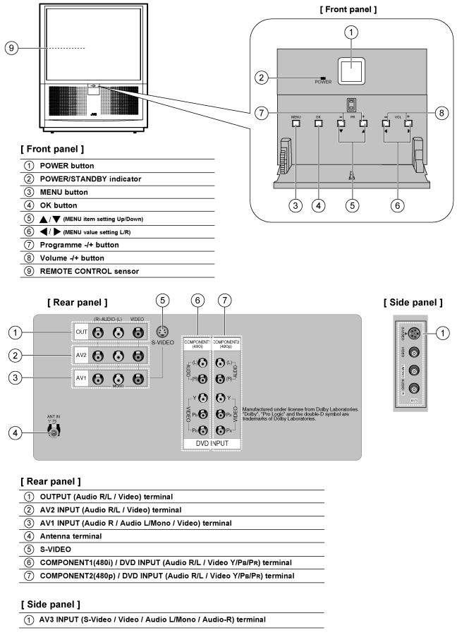
2.1 FUNCTION
1-4 (No.52118)
(No.52118) 1-5
SECTION 3
DISASSEMBLY
This service manual does not describe DISASSEMBLY.
1-6 (No.52118)

|
SECTION 4 |
||
|
ADJUSTMENT |
||
4.1 ADJUSTMENT PREPARATION |
4.2 MEASURING INSTRUMENT |
||
(1) |
There are 2 ways of adjusting this TV: One is with the REMOTE |
(1) |
DC voltmeter (or digital voltmeter) |
|
CONTROL UNIT and the other is the conventional method |
(2) |
HV voltmeter |
|
using adjustment parts and components. |
(3) |
Oscilloscope |
(2) |
The setting (adjustment) using the REMOTE CONTROL UNIT |
(4) |
Signal generator (Pattern generator) |
|
is made on the basis of the initial setting values. The setting |
(5) |
TV audio multiplex signal generator |
|
values which adjust the screen to the optimum condition can be |
(6) |
Remote controller |
|
different from the initial setting values. |
|
|
(3) |
Make sure that connection is correctly made to AC power |
|
|
|
source. |
|
|
(4) |
Turn on the power of the TV and measuring instrument for |
|
|
|
warming up for at least 30 minutes before starting adjustment. |
|
|
(5) |
If the receive or input signal is not specified, use the most |
|
|
|
appropriate signal for adjustment. |
|
|
(6) |
Never touch parts (such as variable resistors, transformers and |
|
|
|
condensers) not shown in the adjustment items of this service |
|
|
|
adjustment. |
|
|
4.3 ADJUSTMENT ITEM |
|
|
|
! RASTER SLANT/FOCUS |
! DEFLECTION CIRCUIT |
||
! BEAM ALIGNMENT |
! LENS FOCUS & ELECTRONIC FOCUS |
||
! CENTER MAGNET |
! CONVERGENCE |
||
! HIGH VOLTAGE REGULATION |
! LENS FOCUS |
||
! CUT-OFF |
|
|
|
4.4 BASIC OPERATION IN SVC(SERVICE MENU) MODE 4.4.1 HOW TO ENTER THE SVC(SERVICE MENU) MODE
(1)Press the [LIST] key and [PSM] key on the REMOTE CONTROL UNIT simultaneously.
(2)The SVC(service menu) mode is displayed.
(3)Select the “SERVICE 1~5” and “OPTION 1~4” with the [SWAP] key.
(4)Select the setting item with the ["/#] key, and set the setting value with the [$/%] keys.
(5)Press the [OK] key to memorize the setting value.
(6)Press the [TV/AV] key, and return to the normal screen.
SVC(service menu) mode
(No.52118) 1-7

1-8 (No.52118)

(No.52118) 1-9
Loading...