


 Loading...
SERVICE MANUAL
COLOUR TELEVISION
HV-34LH21, HV-34LH21/E,
HV-34LH51/S, HV-34LH71/G
BASIC CHASSIS
ML
RM-C1351 RM-C1353 RM-C1350 [HV-34LH21] [HV-34LH51] [HV-34LH71]
TABLE OF CONTENTS
1 PRECAUTION. . . . . . . . . . . . . . . . . . . . . . . . . . . . . . . . . . . . . . . . . . . . . . . . . . . . . . . . . . . . . . . . . . . . . . . . . 1-3 2 SPECIFIC SERVICE INSTRUCTIONS . . . . . . . . . . . . . . . . . . . . . . . . . . . . . . . . . . . . . . . . . . . . . . . . . . . . . . 1-4 3 DISASSEMBLY . . . . . . . . . . . . . . . . . . . . . . . . . . . . . . . . . . . . . . . . . . . . . . . . . . . . . . . . . . . . . . . . . . . . . . . 1-7 4 ADJUSTMENT . . . . . . . . . . . . . . . . . . . . . . . . . . . . . . . . . . . . . . . . . . . . . . . . . . . . . . . . . . . . . . . . . . . . . . . 1-14 5 TROUBLESHOOTING . . . . . . . . . . . . . . . . . . . . . . . . . . . . . . . . . . . . . . . . . . . . . . . . . . . . . . . . . . . . . . . . . 1-33
COPYRIGHT © 2003 VICTOR COMPANY OF JAPAN, LIMITED
No.52200
2003/11
SPECIFICATION
|
|
|
|
|
|
|
|
Contents |
|
|
|
Items |
|
|
|
|
|
|
|
|
|
|
|
|
|
|
HV-34LH21 |
|
|
HV-34LH71/G |
|
HV-34LH51/S |
|||
|
|
|
|
|
HV-34LH21/E |
|
|
|
|||
|
|
|
|
|
|
|
|
|
|
|
|
|
|
|
|
|
|
|
|
|
|||
Dimensions (W × H × |
D) |
|
89.8cm × 72.8cm × 57.9cm |
|
|
|
|
|
|||
|
|
|
|
|
|
|
|
|
|
||
Mass |
|
|
68.0kg |
|
|
|
|
|
|
||
|
|
|
|
|
|
|
|
|
|
||
TV RF System |
|
|
B/G, I, D/K, K1, M |
|
|
|
|
|
|
||
|
|
|
|
|
|
|
|||||
Colour System |
|
|
PAL / SECAM / NTSC 3.58 / NTSC 4.43 |
|
|
|
|||||
|
|
|
|
|
|
|
|||||
Stereo System |
|
|
A2 (B/G) / NICAM (B/G, I, D/K) |
|
|
|
|||||
|
|
|
|
|
|
|
|
|
|
||
Teletext System |
|
|
Fastext (UK system) |
|
|
|
|
|
NON |
||
|
|
|
|
WST(world standard teletext system) |
|
|
|
||||
|
|
|
|
|
|
|
|
|
|||
Receiving |
|
VHF Low |
46.25MHz ~168.25MHz |
|
|
|
|
|
|
||
Frequency |
|
VHF High |
175.25MHz ~ 463.25MHz |
|
|
|
|
|
|||
|
|
|
UHF |
471.25MHz ~ 863.25MHz |
|
|
|
|
|
||
|
|
|
CATV |
Mid |
: X-Z+2, S1~S10 |
|
|
|
|
|
|
|
|
|
|
Super : S11~S20 |
|
|
|
|
|
|
|
|
|
|
|
Hyper : S21~S41 |
|
|
|
|
|
|
|
Intermediate |
|
|
VIF |
38.0MHz |
|
|
|
|
|
|
|
Frequency |
|
|
SIF |
32.5MHz(5.5MHz) / 32.0MHz(6.0MHz) / 3.15MHz(6.5MHz) / 33.5MHz (4.5MHz) |
|||||||
|
|
|
|
|
|
|
|
|
|
|
|
Colour |
|
|
PAL |
4.43MHz |
|
|
|
|
|
|
|
Sub Carrier |
|
|
SECAM |
4.40625MHz / 4.25MHz |
|
|
|
|
|
|
|
Frequency |
|
|
NTSC |
3.58MHz / 4.43MHz |
|
|
|
|
|
|
|
Aerial Input Terminal |
|
|
75Ω |
unbalanced, coaxial |
|
|
|
|
|
||
|
|
|
|
|
|
|
|
|
|||
Power Input |
|
|
AC 110V~240V , 50/60Hz |
|
|
|
|
|
|||
|
|
|
|
|
|
|
|
|
|
||
Power Consumption |
|
|
Avg.150W |
|
|
|
|
|
|
||
|
|
|
|
|
|
||||||
Picture Tube |
|
|
Visible size : 80.1cm (Diagonal) / 64.1cm × 48.1cm (H × |
V) |
|
||||||
|
|
|
|
|
|
|
|||||
High Voltage |
|
|
32.0kV +1.0kV / -1.5kV (At zero beam current) |
|
|
|
|||||
|
|
|
|
|
|
|
|
|
|
||
Speaker |
|
|
5cm × 12cm Oval type × |
2 |
|
|
|
|
|
||
|
|
|
|
|
|
|
|
|
|
||
Audio Power Output |
|
|
10W + 10W |
|
|
|
|
|
|
||
|
|
|
|
|
|
|
|
||||
Video / Audio |
|
|
S-Video |
Mini-DIN 4 pin connector × 1 |
|
|
|
||||
Input |
|
[VIDEO-1] |
Y : 1V(p-p), Positive (Negative sync provided), 75Ω |
|
|
|
|||||
|
|
|
|
C : 0.286V(p-p) (burst signal), 75Ω |
|
|
|
||||
|
|
|
Video |
1V(p-p), negative sync, 75Ω |
, RCA pin jack × 4 |
|
|
|
|||
|
|
Audio(L/R) |
500mV(rms) (-4dBs), High impedance, RCA pin jack × |
8 |
|
|
|||||
|
Component Video |
RCA pin jack × 3 |
|
|
|
|
|
|
|||
|
|
[VIDEO-3] |
Y |
: 1V(p-p), 75Ω |
|
|
|
|
|
|
|
|
|
|
|
CB : 0.7V(p-p), 75Ω |
|
|
|
|
|
|
|
|
|
|
|
CR : 0.7V(p-p), 75Ω |
|
|
|
|
|
|
|
|
|
|
|
|
|
|
|
|
|
||
Video / Audio |
|
|
Video |
1V(p-p) 75Ω , RCA pin jack × |
1 |
|
|
|
|
||
Output |
|
Audio(L/R) |
500mV(rms) (-4dBs), Low impedance, RCA pin jack × |
2 |
|
|
|||||
Headphone |
|
|
3.5mm stereo mini jack × |
1 |
|
|
|
|
|
||
|
|
|
|
|
|
|
|
|
|
||
Remote Control Unit |
|
|
RM-C1351 |
|
|
RM-C1350 |
|
|
RM-C1353 |
||
|
|
|
|
(AA/R06/UM-3 battery × |
2) |
|
(AA/R06/UM-3 battery × |
2) |
(AA/R06/UM-3 battery × 2) |
||
|
|
|
|
|
|
|
|
|
|
|
|
Design & specifications are subject to change without notice.
1-2 (No.52200)

SECTION 1 PRECAUTION
1.1SAFETY PRECAUTIONS
(1)The design of this product contains special hardware, many circuits and components specially for safety purposes. For continued protection, no changes should be made to the original design unless authorized in writing by the manufacturer. Replacement parts must be identical to those used in the original circuits. Service should be performed by qualified personnel only.
(2)Alterations of the design or circuitry of the products should not be made. Any design alterations or additions will void the manufacturer's warranty and will further relieve the manufacturer of responsibility for personal injury or property damage resulting therefrom.
(3)Many electrical and mechanical parts in the products have special safety-related characteristics. These characteristics are often not evident from visual inspection nor can the protection afforded by them necessarily be obtained by using replacement components rated for higher voltage, wattage, etc. Replacement parts which have these special safety characteristics are identified in the parts list of Service manual. Electrical components having such features are identified by shading on the schematics and by (  ) on the parts list in Service manual. The use of a substitute replacement which does not have the same safety characteristics as the recommended replacement part shown in the parts list of Service manual may cause shock, fire, or other hazards.
(4)Don't short between the LIVE side ground and ISOLATED (NEUTRAL) side ground or EARTH side ground when repairing.
Some model's power circuit is partly different in the GND. The difference of the GND is shown by the LIVE : (  ) side GND, the ISOLATED (NEUTRAL) : (
  ) side GND and EARTH : (
  ) side GND.
Don't short between the LIVE side GND and ISOLATED (NEUTRAL) side GND or EARTH side GND and never measure the LIVE side GND and ISOLATED (NEUTRAL) side GND or EARTH side GND at the same time with a measuring apparatus (oscilloscope etc.). If above note will not be kept, a fuse or any parts will be broken.
(5)If any repair has been made to the chassis, it is recommended that the B1 setting should be checked or adjusted (See B1 POWER SUPPLY check).
(6)The high voltage applied to the picture tube must conform with that specified in Service manual. Excessive high voltage can cause an increase in X-Ray emission, arcing and possible component damage, therefore operation under excessive high voltage conditions should be kept to a minimum, or should be prevented. If severe arcing occurs, remove the AC power immediately and determine the cause by visual inspection (incorrect installation, cracked or melted high voltage harness, poor soldering, etc.). To maintain the proper minimum level of soft X-Ray emission, components in the high voltage circuitry including the picture tube must be the exact replacements or alternatives approved by the manufacturer of the complete product.
(7)Do not check high voltage by drawing an arc. Use a high voltage meter or a high voltage probe with a VTVM. Discharge the picture tube before attempting meter
connection, by connecting a clip lead to the ground frame and connecting the other end of the lead through a 10kΩ 2W resistor to the anode button.
(8)When service is required, observe the original lead dress. Extra precaution should be given to assure correct lead dress in the high voltage circuit area. Where a short circuit has occurred, those components that indicate evidence of overheating should be replaced. Always use the manufacturer's replacement components.
(9)Isolation Check (Safety for Electrical Shock Hazard)
After re-assembling the product, always perform an isolation check on the exposed metal parts of the cabinet (antenna terminals, video/audio input and output terminals, Control knobs, metal cabinet, screw heads, earphone jack, control shafts, etc.) to be sure the product is safe to operate without danger of electrical shock.
a)Dielectric Strength Test
The isolation between the AC primary circuit and all metal parts exposed to the user, particularly any exposed metal part having a return path to the chassis should withstand a voltage of 3000V AC (r.m.s.) for a period of one second. (.
. . . Withstand a voltage of 1100V AC (r.m.s.) to an appliance rated up to 120V, and 3000V AC (r.m.s.) to an appliance rated 200V or more, for a period of one second.) This method of test requires a test equipment not generally found in the service trade.
b)Leakage Current Check
Plug the AC line cord directly into the AC outlet (do not use a line isolation transformer during this check.). Using a "Leakage Current Tester", measure the leakage current from each exposed metal part of the cabinet, particularly any exposed metal part having a return path to the chassis, to a known good earth ground (water pipe, etc.). Any leakage current must not exceed 0.5mA AC (r.m.s.).
However, in tropical area, this must not exceed 0.2mA AC (r.m.s.).
Alternate Check Method
Plug the AC line cord directly into the AC outlet (do not
use a line isolation transformer during this check.). Use an AC voltmeter having 1000Ω per volt or more sensitivity in the following manner. Connect a 1500Ω 10W resistor paralleled by a 0.15µF AC-type capacitor between an exposed metal part and a known good earth ground (water pipe, etc.). Measure the AC voltage across the resistor with the AC voltmeter. Move the resistor connection to each exposed metal part, particularly any exposed metal part having a return path to the chassis, and measure the AC voltage across the resistor. Now, reverse the plug in the AC outlet and repeat each measurement. Any voltage measured must not exceed 0.75V AC (r.m.s.). This corresponds to 0.5mA AC (r.m.s.).
However, in tropical area, this must not exceed 0.3V AC (r.m.s.). This corresponds to 0.2mA AC (r.m.s.).
AC VOLTMETER (HAVING 1000 /V,
/V,
OR MORE SENSITIVITY)
0.15 F AC-TYPE |
|
||
|
|
PLACE THIS PROBE |
|
1500 |
10W |
ON EACH EXPOSED |
|
METAL PART |
|||
|
|
||
GOOD EARTH GROUND
(No.52200)1-3
SECTION 2
SPECIFIC SERVICE INSTRUCTIONS
2.1FEATURES
•New chassis design enable use of an interactive on-screen control.
•The TELETEXT SYSTEM has a built-in FASTEXT (UK system), and WST (world standard teletext system). [Only HV-34LH21, HV-34LH21/E, HV-34LH71/G]
•Pure FLAT CRT reproduce fine textured.
•Digi Pure pro : Auto digi pure with motion picture compensation.
•Because this TV unit corresponds to multiplex broadcast, users can enjoy music programs and sporting events with live realism. In addition, BILINGUAL programs can be heard in their original language.
2.2MAIN DIFFERENCE LIST
Item |
HV-34LH21 |
HV-34LH21/E |
HV-34LH51/S |
HV-34LH71/G |
|
|
|
|
|
TELETEXT |
YES |
YES |
NO |
YES |
|
|
|
|
|
PIP |
NO |
NO |
YES |
YES |
|
|
|
|
|
COLOUR AUTO |
NO |
NO |
YES |
NO |
|
|
|
|
|
BLUE BACK MUTE |
NO |
NO |
YES |
NO |
|
|
|
|
|
MAIN PWB ASSY |
SML-1502A-H2 |
SML-1507A-H2 |
SML-1505A-H2 |
SML-1504A-H2 |
|
|
|
|
|
POWER &DEF PWB ASSY |
SML-2502A-H2 |
SML-2504A-H2 |
SML-2502A-H2 |
SML-2502A-H2 |
|
|
|
|
|
MICOM /100Hz PWB ASSY |
SML0Z502A-H2 |
SML0Z502A-H2 |
SML0Z501A-H2 |
SML0Z501A-H2 |
|
|
|
|
|
AV SW PWB ASSY |
SML0J502A-H2 |
SML0J502A-H2 |
SML0J504A-H2 |
SML0J504A-H2 |
|
|
|
|
|
REMOTE CONTROL UNIT |
RM-C1351-1H |
RM-C1351-1H |
RM-C1353-1H |
RM-C1350-2H |
|
|
|
|
|
1-4 (No.52200)

2.3FUNCTIONS
FRONT TERMINAL & CONTROL
|
OVER |
|
|
|
|
|
|
S |
V |
L/MONO |
R |
MENU |
CHANNEL |
VOLUME |
TV/VIDEO |
|
|
|
|||||
|
IN (VIDEO-4) |
|
OK |
|
|
EXIT |
|
1 |
|
2 |
|
3 |
4 |
5 |
6 |
1HEADPHONE jack
2VIDEO-4 terminal (S-VIDEO / VIDEO / L/MONO / R)
3MENU/OK button
4CHANNEL -/+ (MENU UP/DOWN) button
5VOLUME -/+ (MENU LEFT/RIGHT) button
REAR TERMINAL
POWER
7 |
8 |
9 |
6TV / VIDEO / EXIT button
7Remote Control sensor
8POWER lamp
9POWER button
|
|
|
|
1 |
2 |
3 |
4 |
|
AUDIO |
|
|
S |
|
|
|
R |
L/MONO VIDEO |
|
|
|
|||
|
|
|
|
OVER |
|
|
|
|
|
|
|
VIDEO-1 |
|
|
|
|
|
|
|
VIDEO-2 |
|
|
|
|
CR |
CB |
Y/VIDEO |
|
|
|
|
|
AUDIO |
|
|
VIDEO-3/ |
|
|
|
R |
L/MONO |
|
COMPONENT |
|
|
|
|
OUTPUT
R L
AUDIO VIDEO
5
1VIDEO-1 (INPUT) terminal (S, VIDEO, L/MONO ,R)
2VIDEO-2 (INPUT) terminal ( VIDEO, L/MONO ,R)
3VIDEO-3 (INPUT) terminal
(Y/VIDEO, CB,CR , L/MONO, R) /COMPONENT
4OUTPUT (VIDEO, AUDIO L/R) terminal (VIDEO, L, R)
5AERIAL socket
(No.52200)1-5

REMOTE CONTROL UNIT
RM-C1351 |
|
RM-C1353 |
|
RM-C1350 |
[HV-34LH21,HV-34LH21/E] |
|
[HV-34LH51/S] |
|
[HV-34LH71/G] |
|
|
|
|
|
5 |
1 |
5 |
1 |
5 |
1 |
|
6 |
2 |
6 |
2 |
6 |
2 |
|
7 |
3 |
7 |
3 |
7 |
3 |
|
8 |
|
8 |
4 |
8 |
4 |
|
9 |
10 |
9 |
10 |
9 |
10 |
|
12 |
11 |
12 |
|
12 |
11 |
|
13 |
|
13 |
|
13 |
|
|
14 |
17 |
14 |
17 |
14 |
17 |
|
|
18 |
15 |
18 |
15 |
18 |
|
16 |
16 |
16 |
||||
|
|
|
||||
20 |
19 |
20 |
19 |
20 |
19 |
21 |
21 |
21 |
1 |
POWER key |
|
|
1 |
POWER key |
|
|
1 |
POWER key |
|
|
2 |
ZOOM key |
|
|
2 |
ZOOM key |
|
|
2 |
ZOOM key |
|
|
3 |
CINEMA SURROUND key |
3 |
CINEMA SURROUND key |
3 |
CINEMA SURROUND key |
||||||
5 |
MUTING key |
|
|
4 |
PIP key |
|
|
4 |
PIP key |
|
|
6 |
COLOUR SYSTEM key |
5 |
MUTING key |
|
|
5 |
MUTING key |
|
|
||
7 |
SOUND SYSTEM key |
6 |
COLOUR SYSTEM key |
6 |
COLOUR SYSTEM key |
||||||
8 |
DISPLAY key |
|
|
7 |
SOUND SYSTEM key |
7 |
SOUND SYSTEM key |
||||
9 |
MENU ( / & / ) keys |
8 |
DISPLAY key |
|
|
8 |
DISPLAY key |
|
|
||
10 |
MENU / OK key |
|
9 |
MENU ( / & / ) keys |
9 |
MENU ( / & / ) keys |
|||||
11 |
TV/TEXT key |
|
|
10 |
MENU / OK key |
|
10 |
MENU / OK key |
|
||
12 |
STEREO / |
key |
|
12 |
STEREO / |
key |
|
11 |
TV/TEXT key |
|
|
|
:Stereo / |
:Mono |
|
:Stereo / |
:Mono |
12 |
STEREO / |
key |
|
||
|
:Bilingual (sub |
) |
|
:Bilingual (sub |
) |
|
:Stereo / |
:Mono |
|||
|
:Bilingual (sub |
) |
|
:Bilingual (sub |
) |
|
:Bilingual (sub |
) |
|||
13 |
TV / VIDEO key |
|
13 |
TV / VIDEO key |
|
|
:Bilingual (sub |
) |
|||
14 |
PICTURE MODE key |
14 |
PICTURE MODE key |
13 |
TV / VIDEO key |
|
|||||
16 |
RETURN + key |
|
|
15 |
SUB-P +/- key |
|
|
14 |
PICTURE MODE key |
||
17 |
CHANNEL keys |
|
16 |
RETURN + key |
|
|
15 |
SUB-P +/- key |
|
|
|
18 |
-/-- key |
|
|
17 |
CHANNEL keys |
|
16 |
RETURN + key |
|
|
|
19 |
VOLUME +/- keys |
|
18 |
-/-- key |
|
|
17 |
CHANNEL keys |
|
||
20 |
CHANNEL +/- keys |
|
19 |
VOLUME +/- keys |
|
18 |
-/-- key |
|
|
||
21 |
FAVORITE CH keys |
|
20 |
CHANNEL +/- keys |
|
19 |
VOLUME +/- keys |
|
|||
|
|
|
|
21 |
FAVORITE CH keys |
|
20 |
CHANNEL +/- keys |
|
||
|
|
|
|
|
|
|
|
21 |
FAVORITE CH keys |
|
|
1-6 (No.52200)
SECTION 3
DISASSEMBLY
3.1DISASSEMBLY PROCEDURE
3.1.1REMOVING THE REAR COVER
(1) Unplug the power cord.
(2) Remove the 18 screws [A] as shown in the Fig. 1.
(3) Withdraw the REAR COVER toward you.
3.1.2REMOVING THE AV TERMINAL BOARD
•Remove the REAR COVER.
(1)Remove the 5 screws [B] as shown in the Fig. 1.
(2)Withdraw the AV TERMINAL BOARD toward you.
3.1.3REMOVING THE CHASSIS
• Remove the REAR COVER.
(1) Slightly raise the both sides of the CHASSIS by hand and remove the 2 claws under the both sides of the CHASSIS from the front cabinet.
(2) Withdraw the CHASSIS backward.
(If necessary, take off the wire clamp, connectors etc.)
3.1.4REMOVING THE SPEAKER
•Remove the REAR COVER.
(1)Remove the 2 screws [C], and remove the SP HOLDER as shown in Fig. 1.
NOTE :
When removing the screws [C] of the SP HOLDER, remove the lower side screw first, and then remove the upper one.
(2)Remove the 4screws [D] attaching the SPEAKER.
(3)Follow the same steps when removing the other SPEAKER.
3.1.5 CHECKING THE PW BOARD
•To check the back side of the PW Board.
(1)Pull out the CHASSIS. (Refer to REMOVING THE CHASSIS).
(2)Erect the CHASSIS vertically so that you can easily check the back side of the PW Board.
3.1.6 CAUTION
•When erecting the CHASSIS, be careful so that there will be no contacting with other PW Board.
•Before turning on power, make sure that the wire connector is properly connected.
•When conducting a check with power supplied, be sure to confirm that the CRT EARTH WIRE (BRAIDED ASS'Y) is connected to the CRT SOCKET PW board.
3.1.7 WIRE CLAMPING AND CABLE TYING
(1)Be sure to clamp the wire.
(2)Never remove the cable tie used for tying the wires together.
Should it be inadvertently removed, be sue to tie the wires with a new cable tie.
(No.52200)1-7

FRONT CABINET
SP HOLDER
|
FRONT CONTROL |
|
|
PWB (1/2) |
|
|
C |
|
|
(X2) |
|
|
CONTROL |
|
|
BASE |
|
SP HOLDER |
D |
|
(X4) |
||
|
||
|
SPEAKER |
|
C |
|
(X2) |
|
C |
|
(X4) |
CRT SOCKET |
SPEAKER |
|
|
PWB |
FRONT CONTROL |
|
|
|
PWB (2/2) |
MICOM / 100Hz
PWB
CLAW
FBT
AV
TERMINAL
BOARD
POWER & DEF.
PWB
CLAW
MAIN PWB
AV SW
PWB
B
(X5)
POWER CORD
REAR COVER
A
(X18)
Fig.1
1-8 (No.52200)

3.2REMOVING THE CRT
NOTE:
•Replacement of the CRT should be performed by 2 or more persons.
•After removing the REAR COVER, CHASSIS etc.,
(1)Putting the CRT change table on soft cloth, the CRT change table should also be covered with such soft cloth (shown in Fig. 3).
(2)While keeping the surface of CRT down, mount the TV set on the CRT change table balanced will as shown in Fig. 3.
(3)Remove 4 screws marked by arrows with a box type screwdriver as shown in Fig. 4.
NOTE:
Since the cabinet will drop when screws have been removed, be sure to support the cabinet with hands.
(4)After 4 screws have been removed, put the cabinet slowly on cloth (At this time, be carefully so as not to damage the front
surface of the cabinet) shown in Fig. 5.
NOTE:
•The CRT should be assembled according to the opposite sequence of its dismounting steps.
•The CRT change table should preferably be smaller that the CRT surface, and its height be about 35cm.
CRT CHANGE TABLE
APPROX.
35cm
CLOTH 
Fig.3
CRT
CRT CHANGE TABLE
BOX
TYPE SCREW DRIVER
Fig.4
CRT
CABINET |
CRT |
|
CHANGE TABLE |
||
|
Fig.5
COATING OF SILICON GREASE FOR ELECTRICAL INSULATION ON THE CRT ANODE CAP SECTION.
Subsequent to replacement of the CRT and HV transformer or repair of the anode cap, etc. by dismounting them, be sure to coat silicon grease for electrical insulation as shown in Fig.6.Wipe around the anode button with clean and dry cloth. (Fig.6)Coat silicon grease on the section around the anode button. At this time, take care so that any silicon greases dose not sticks to the anode button. (Fig.7)
Silicon grease product No. KS - 650N
CRT |
Anode button |
Silicon grease coating
Fig.6
Approx. |
|
|
|
|
|
|
|
|
|
Silicon grease |
||||
20mm (Do not |
|
|
|
|
|
|
|
|
|
|
|
|
|
should be coated |
|
|
|
|
|||||||||||
coat grease on |
|
|
|
|
|
|
|
|
|
|
by 5mm or more |
|||
this section |
|
|
|
|
|
|
|
|
|
|
|
|
from the outside |
|
|
|
|
|
|
|
|||||||||
|
|
|
|
|
|
|
|
|
|
|
|
|
|
diameter of anode |
|
|
|
|
|
|
|
|
|
|
|
|
|
|
|
|
|
|
|
|
|
|
|
|
|
|
|
|
|
cap. |
|
|
|
|
|
|
|
|
|
|
|
|
|
|
|
Anode button |
Coating position |
|
(No sticking of |
||
of silicon grease |
||
silicon grease) |
||
|
||
|
Anode cap |
Fig.7
(No.52200)1-9
3.3MEMORY IC REPLACEMENT
3.3.1MEMORY IC
This TV use memory IC.
In the memory IC, there are memorized data for correctly operating the video and deflection circuits.
When replacing memory IC, be sure to use IC written with the initial values of data.
3.3.2PROCEDURE FOR REPLACING MEMORY IC
(1)Power off
Switch the power off and disconnect the power cord from the wall outlet.
(2)Replace the memory IC
Be sure to use a memory IC written with the initial data values.
(3)Power on
Connect the power plug into the wall outlet and switch the power on.
(4)Check and setting of SYSTEM CONSTANT SET
•It must not adjust without signal.
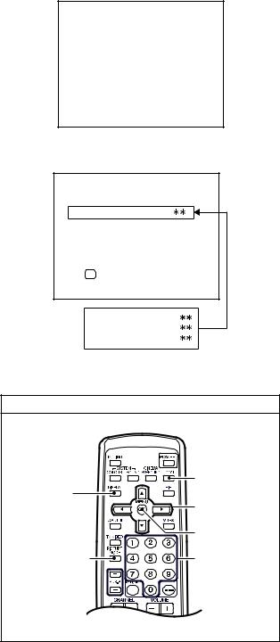
a)Press the [DISPLAY] key and the [PICTURE MODE] key of the REMOTE CONTROL UNIT simultaneously.
b)The SERVICE MENU screen of Fig. 1 will be displayed.
c)While the SERVICE MENU is displayed, press the [DISPLAY] key and [PICTURE MODE] key simultaneously, and the SYSTEM CONSTANT SET screen of Fig. 2 will be displayed.
d)Check the setting values of the SYSTEM
CONSTANT SETTING. If the value is different, select
the setting item with the [MENU |
/ ] key, and set |
the correct value with the [MENU |
/ ] key. |
e)Press the [OK] key to memorize the setting value.
f)Press the [DISPLAY] key, and return to the normal screen.
(5)Receive channels setting
Refer to the OPERATING INSTRUCTIONS and set the receive channels (channels preset) as described.
(6)User settings
Check the user setting values and if setting value is different, set the correct value. For setting, refer to the OPERATING INSTRUCTIONS.
(7)Setting of SERVICE MENU
Verify the setting items of the SERVICE MENU, and reset where necessary. For setting, refer to the SERVICE ADJUSTMENTS.
SERVICE MENU
1. IF |
2. V/C |
3. AUDIO |
4. DEF |
5. VSM PRESET |
6. STATUS |
7.PIP |
8. SURROUND |
9. SHIPPING(OFF) |
0. BUS FREE |
1-9 : SELECT |
DISP : EXIT |
Fig.1
|
SYSTEM CONTANT SET |
|
1. TEXT |
|
|
-/+ |
OK : STORE |
DISP : EXIT |
2. PIP
3. COLOUR AUTO
4. BLUE BACK MUTE
Fig.2
SERVICE MENU
|
ZOOM |
DISPLAY key |
(ASPECT) key |
|
|
|
MENU key |
|
( / & / ) |
|
OK key |
PICTURE MODE |
Numbers keys |
key |
|
[RM-C1350]
Fig.3
1-10 (No.52200)
3.3.3 FACTORY SETTING VALUES
Setting item |
Setting value |
Setting item |
Setting value |
|
|
|
|
MAIN POWER SW |
OFF |
SUB POWER SW |
ON |
|
|
|
|
CHANNEL |
PR1 |
DISPLAY |
INDICATED |
|
|
|
|
PRESET CHANNEL |
See OPERATING INSTRUCTIONS. |
VOLUME |
10 |
|
|
|
|
MENU SETTING
Setting item |
Setting value |
Setting item |
|
|
Setting value |
|
|
|
|
|
|
||
PICTURE SETTING |
|
SOUND |
|
|
||
|
|
|
|
|
|
|
PICTURE MODE |
BRIGHT |
BASS |
|
Center |
|
|
|
|
|
|
|
|
|
CONTRAST |
Center |
TREBLE |
|
Center |
|
|
|
|
|
|
|
|
|
BRIGHT |
Center |
BALANCE |
|
Center |
|
|
|
|
|
|
|
|
|
SHARP |
Center |
CINEMA SURROUND |
|
OFF |
|
|
|
|
|
|
|
|
|
COLOUR |
Center |
AI VOLUME |
|
ON |
|
|
|
|
|
|
|
|
|
WHITE BALANCE |
MID |
|
INSTALL |
|
|
|
|
|
|
|
|
|
|
AI ECO SENSOR DISPLAY |
OFF |
LANGUAGE |
|
ENGLISH |
||
|
|
|
|
|
|
|
PICTURE FEATURES |
EDIT |
|
PRESET CHANNEL ONLY |
|||
|
|
|
|
|
|
|
DIGITAL VNR |
AUTO |
|
|
OTHER : NON (SPACE) |
||
|
|
|
|
|
||
Digi Pure |
AUTO |
AUTO PROGRAM |
|
GROUP-1 : HV-34LH21 |
||
|
|
|
|
|
||
PULL DOWN |
AUTO |
TELETEXT LANGUAGE |
|
GROUP-2 : Unused |
||
|
|
|
|
|
||
COLOUR SYSTEM |
TV : Depends on PR/CH |
|
|
GROUP-3 : HV-34LH21/E |
||
|
EXT : AUTO |
|
|
|
|
|
|
|
|
GROUP-4 : HV-34LH51/S |
|||
|
|
|
|
|||
|
|
|
|
|
|
|
ZOOM |
REGULAR |
|
|
|
HV-34LH71/G |
|
|
|
|
|
|
||
PICTURE TILT |
Center |
|
|
GROUP-5 : Unused |
||
|
|
|
|
|
|
|
FAVORITE CH SETTING |
PRO1 : RED |
|
FEATURES |
|
|
|
|
PRO2 : GREEN |
|
|
|
|
|
|
SLEEP TIMER |
|
OFF |
|
|
|
|
PRO3 : YELLOW |
|
|
|
||
|
|
|
|
|
|
|
|
BLUE BACK |
|
ON |
|
|
|
|
PRO4 : BLUE |
|
|
|
||
|
PICTIRE MODE : BRIGHT |
CHILD LOCK |
|
OFF (for all the channels) |
||
|
DIGITAL VNR : AUTO |
|
|
|
|
|
|
CHANNEL GUARD |
|
ALL CH : OFF |
|||
|
WHITE BALANCE : MID |
|
||||
|
|
|
|
|
|
|
|
AUTO SHUT OFF |
|
OFF |
|
|
|
|
Digi Pure : AUTO |
|
|
|
||
|
PICTURE EFFRCT : OFF |
VIDEO-3 SETTING |
|
COMPONENT |
||
|
|
|
|
|
|
|
|
|
PIP / TWIN |
|
OFF |
|
Only |
|
|
|
|
|
|
HV-34LH51/S |
VIDEO SETTING |
VIDEO STATAS : VIDEO1 |
SUB INPUT |
|
VIDEO1 |
|
|
|
|
HV-34LH71/G |
||||
|
PICTURE MODE : BRIGHT |
|
|
|
|
|
|
|
|
|
|
|
|
|
DIGITAL VNR: AUTO |
|
|
|
|
|
|
|
|
|
|
|
|
|
WHITE BALANCE : MID |
|
|
|
|
|
|
Digi Pure : AUTO |
|
|
|
|
|
|
PICTURE EFFECT : OFF |
|
|
|
|
|
(No.52200)1-11
Loading...