


VIDEO CASSETTE RECORDER
HR-S9500U
VCR TV CABLE/DBS |
AUDIO |
POWER |
|
MONITOR |
|
TV/VCR |
ENTER/OSD |
DISPLAY |
1 |
2 |
|
|
3 |
|
|
|
|
|
|
|
|
|
|
2 |
|
|
|
|
4 |
5 |
|
|
6 |
|
|
|
|
|
DBS |
DAILY(M-F) |
WEEKLY |
|
|
|
|
|||
7 |
8 |
|
|
9 |
|
|
|
|
|
C. RESET |
AUX |
|
|
|
|
|
|
|
|
CANCEL |
0 |
|
TIMER 4 |
|
|
|
|
||
START |
STOP |
DATE |
|
CH |
|
|
|
|
|
|
EXPRESS PROGRAMMING |
|
|
|
|
|
|||
1 PROG |
PROG |
SP/EP |
SKIP SEARCH |
|
|
|
|
||
CHECK |
|
|
|
|
|
|
|
||
|
|
PLAY |
|
FF |
|
|
|
|
|
REW |
|
|
|
|
|
|
|
||
REC |
STOP |
PAUSE |
|
|
|
|
|||
|
|
|
|
|
|
||||
|
|
TV CH + |
|
|
|
|
|
|
|
|
|
|
|
|
|
|
STOP/EJECT |
PLAY |
DIGITAL |
TV |
|
TIME |
|
|
TV |
|
S-VHS ET MENU |
|
TBC/NR |
VOL |
|
|
|
VOL |
|
|
|||
– |
|
SCAN |
|
+ |
|
|
|
|
|
|
|
|
|
|
POWER |
|
|
|
|
M |
ENU |
TV CH – |
3 |
OK |
|
|
|
|
|
|
A/B |
|
|
|
|
|
|
||
|
|
|
JOG/ |
|
|
|
|
|
|
|
|
|
SHUTTLE |
|
|
|
|
|
|
|
|
|
|
|
|
|
|
PAUSE |
|
|
|
|
|
|
S-VIDEO |
VIDEO |
(MONO)L – AUDIO – R |
|
|
|
|
|
|
|
PUSH-OPEN |
|
|
|
|
|
|
|
|
|
|
|
|
PUSH-OPEN |
|
INSTRUCTIONS
For Customer Use:
Enter below the Model No. and Serial No. which are located on the rear of cabinet. Retain this information for future reference.
Model No.
Serial No.
LPT0027-001B
2

 EN
EN


Dear Customer,
Thank you for purchasing the JVC VHS video cassette recorder. Before use, please read the safety information and precautions contained in the following pages to ensure safe use of your new VCR.
CAUTIONS
CAUTION
RISK OF ELECTRIC SHOCK
DO NOT OPEN
CAUTION: TO REDUCE THE RISK OF ELECTRIC SHOCK.
DO NOT REMOVE COVER (OR BACK).
NO USER-SERVICEABLE PARTS INSIDE.
REFER SERVICING TO QUALIFIED SERVICE PERSONNEL.
The lightning flash with arrowhead symbol, within an equilateral triangle, is intended to alert the user to the presence of uninsulated "dangerous voltage" within the product's enclosure that may be of sufficient magnitude to constitute a risk of electric shock to persons.
The exclamation point within an equilateral triangle is intended to alert the user to the presence of important operating and maintenance (servicing) instructions in the literature accompanying the appliance.
WARNING:
TO PREVENT FIRE OR SHOCK HAZARD, DO NOT EXPOSE THIS UNIT TO RAIN OR MOISTURE.
CAUTION:
This video cassette recorder should be used with AC 120V`, 60Hz only.
To prevent electric shocks and fire hazards, DO NOT use any other power source.
CAUTION:
TO PREVENT ELECTRIC SHOCK, MATCH WIDE BLADE OF PLUG TO WIDE SLOT, FULLY INSERT.
ATTENTION:
POUR ÉVITER LES CHOCS ÉLECTRIQUES, INTRODUIRE LA LAME LA PLUS LARGE DE LA FICHE DANS LA BORNE CORRESPONDANTE DE LA PRISE ET POUSSER JUSQU'AU FOND.
Note to CATV system installer:
This reminder is provided to call the CATV system installer's attention to Article 820-40 of the NEC that provides guidelines for proper grounding and, in particular, specifies that the cable ground shall be connected to the grounding system of the building, as close to the point of cable entry as practical.
Failure to heed the following precautions may result in damage to the VCR, remote control or video cassette.
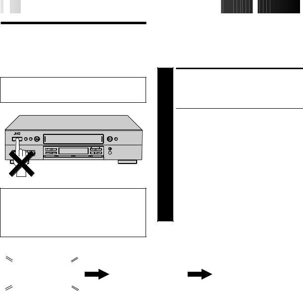
1.DO NOT place the VCR . . .
... in an environment prone to extreme temperatures or humidity.
... in direct sunlight.
... in a dusty environment.
... in an environment where strong magnetic fields are generated.
... on a surface that is unstable or subject to vibration.
2.DO NOT block the VCR’s ventilation openings.
3.DO NOT place heavy objects on the VCR or remote control.
4.DO NOT place anything which might spill on top of the VCR or remote control.
5.AVOID violent shocks to the VCR during transport.
**MOISTURE CONDENSATION
Moisture in the air will condense on the VCR when you move it from a cold place to a warm place, or under extremely humid conditions—just as water droplets form on the surface of a glass filled with cold liquid. Moisture condensation on the head drum will cause damage to the tape. In conditions where condensation may occur, keep the VCR’s power turned on for a few hours to let the moisture dry before inserting a tape.
**ABOUT HEAD CLEANING
Accumulation of dirt and other particles on the video heads may cause the playback picture to become blurred or interrupted. Be sure to contact your nearest JVC dealer if such troubles occur.
VCR Plus+C3 and PlusCode are trademarks of Gemstar Development Corporation.
The VCR Plus+ system is manufactured under license from Gemstar Development Corporation.
DSSTM is an official trademark of DIRECTV, Inc., a unit of GM Hughes Electronics. PRIMESTAR is a registered service mark of Primestar Partners, L.P. DISH NetworkTM is a trademark of Echostar Communications Corporation.
MOVIE ADVANCETM and COMMERCIAL ADVANCE® are trademarks of SRT, Inc. A Jerry Iggulden invention licensed in association with Arthur D. Little Enterprises, Inc.
CAUTION:
Changes or modifications not approved by JVC could void user's authority to operate the equipment.
nCassettes marked "S-VHS" and "VHS" can be used with this video cassette recorder. However, S-VHS recordings are possible only with cassettes marked "S-VHS".
By using S-VHS ET it is possible to record and play back with S-VHS picture quality on VHS cassettes with this VCR.
nAs an ENERGY STAR® Partner, JVC has determined that this product or product model meets the ENERGY STAR® guidelines for energy efficiency.

IMPORTANT PRODUCT SAFETY INSTRUCTIONS
Electrical energy can perform many useful functions. But improper use can result in potential electrical shock or fire hazards. This product has been engineered and manufactured to assure your personal safety. In order not to defeat the built-in safeguards, observe the following basic rules for its installation, use and servicing.
ATTENTION:
Follow and obey all warnings and instructions marked on your product and its operating instructions. For your safety, please read all the safety and operating instructions before you operate this product and keep this booklet for future reference.
INSTALLATION
1. Grounding or Polarization
(A)Your product may be equipped with a polarized alternatingcurrent line plug (a plug having one blade wider than the other). This plug will fit into the power outlet only one way. This is a safety feature.
If you are unable to insert the plug fully into the outlet, try reversing the plug. If the plug should still fail to fit, contact your electrician to replace your obsolete outlet. Do not defeat the safety purpose of the polarized plug.
(B)Your product may be equipped with a 3-wire grounding-type plug, a plug having a third (grounding) pin. This plug will only fit into a grounding-type power outlet. This is a safety feature.
If you are unable to insert the plug into the outlet, contact your electrician to replace your obsolete outlet. Do not defeat the safety purpose of the grounding-type plug.
2. Power Sources
Operate your product only from the type of power source indicated on the marking label. If you are not sure of the type of power supply to your home, consult your product dealer or local power company. If your product is intended to operate from battery power, or other sources, refer to the operating instructions.
3. Overloading
Do not overload wall outlets, extension cords, or integral convenience receptacles as this can result in a risk of fire or electric shock.
4. Power Cord Protection
Power supply cords should be routed so that they are not likely to be walked on or pinched by items placed upon or against them, paying particular attention to cords at plugs, convenience receptacles, and the point where they exit from the product.


 EN
EN
 3
3
5. Ventilation
Slots and openings in the cabinet are provided for ventilation. To ensure reliable operation of the product and to protect it from overheating, these openings must not be blocked or covered.
•Do not block the openings by placing the product on a bed, sofa, rug or other similar surface.
•Do not place the product in a built-in installation such as a bookcase or rack unless proper ventilation is provided or the manufacturer’s instructions have been adhered to.
6. Wall or Ceiling Mounting
The product should be mounted to a wall or ceiling only as recommended by the manufacturer.
ANTENNA INSTALLATION
INSTRUCTIONS
1. Outdoor Antenna Grounding
If an outside antenna or cable system is connected to the product, be sure the antenna or cable system is grounded so as to provide some protection against voltage surges and built-up static charges. Article 810 of the National Electrical Code, ANSI/NFPA 70, provides information with regard to proper grounding of the mast and supporting structure, grounding of the lead-in wire to an antenna discharge unit, size of grounding connectors, location of antenna discharge unit, connection to grounding electrodes, and requirements for the grounding electrode.
2. Lightning
For added protection for this product during a lightning storm, or when it is left unattended and unused for long periods of time, unplug it from the wall outlet and disconnect the antenna or cable system. This will prevent damage to the product due to lightning and power-line surges.
3. Power Lines
An outside antenna system should not be located in the vicinity of overhead power lines or other electric light or power circuits, or where it can fall into such power lines or circuits. When installing an outside antenna system, extreme care should be taken to keep from touching such power lines or circuits as contact with them might be fatal.
EXAMPLE OF ANTENNA GROUNDING AS PER
NATIONAL ELECTRICAL CODE, ANSI/NFPA 70
ANTENNA
LEAD IN WIRE
GROUND CLAMP
ANTENNA DISCHARGE UNIT (NEC SECTION
ELECTRIC SERVICE 810-20) EQUIPMENT 

GROUNDING CONDUCTORS
(NEC SECTION 810-21)
GROUND CLAMPS
POWER SERVICE GROUNDING ELECTRODE SYSTEM (NEC ART 250. PART H)
NEC – NATIONAL ELECTRICAL CODE

4

 EN
EN


USE
1. Accessories
To avoid personal injury:
•Do not place this product on an unstable cart, stand, tripod, bracket, or table. It may fall, causing serious injury to a child or adult, and serious damage to the product.
•Use only with a cart, stand, tripod, bracket, or table recommended by the manufacturer or sold with the product.
•Use a mounting accessory recommended by the manufacturer and follow the manufacturer’s instructions for any mounting of the product.
•Do not try to roll a cart with small casters across thresholds or deep-pile carpets.
2.Product and Cart Combination
A product and cart combination should be moved with care. Quick stops, excessive force, and uneven surfaces may cause the product and cart combination to overturn.
3.Water and Moisture
PORTABLE CART WARNING (Symbol provided by RETAC)
Do not use this product near water—for example, near a bath tub, wash bowl, kitchen sink or laundry tub, in a wet basement, or near a swimming pool and the like.
4. Object and Liquid Entry
Never push objects of any kind into this product through openings as they may touch dangerous voltage points or shortout parts that could result in a fire or electric shock. Never spill liquid of any kind on the product.
5. Attachments
Do not use attachments not recommended by the manufacturer of this product as they may cause hazards.
6. Cleaning
Unplug this product from the wall outlet before cleaning. Do not use liquid cleaners or aerosol cleaners. Use a damp cloth for cleaning.
7. Heat
The product should be situated away from heat sources such as radiators, heat registers, stoves, or other products (including amplifiers) that produce heat.
SERVICING
1. Servicing
If your product is not operating correctly or exhibits a marked change in performance and you are unable to restore normal operation by following the detailed procedure in its operating instructions, do not attempt to service it yourself as opening or removing covers may expose you to dangerous voltage or other hazards. Refer all servicing to qualified service personnel.
2. Damage Requiring Service
Unplug this product from the wall outlet and refer servicing to qualified service personnel under the following conditions:
a.When the power supply cord or plug is damaged.
b.If liquid has been spilled, or objects have fallen into the product.
c.If the product has been exposed to rain or water.
d.If the product does not operate normally by following the operating instructions. Adjust only those controls that are covered by the operating instructions as an improper adjustment of other controls may result in damage and will often require extensive work by a qualified technician to restore the product to its normal operation.
e.If the product has been dropped or damaged in any way.
f.When the product exhibits a distinct change in performance—this indicates a need for service.
3. Replacement Parts
When replacement parts are required, be sure the service technician has used replacement parts specified by the manufacturer or have the same characteristics as the original part. Unauthorized substitutions may result in fire, electric shock or other hazards.
4. Safety Check
Upon completion of any service or repairs to this product, ask the service technician to perform safety checks to determine that the product is in safe operating condition.
HOW TO USE THIS INSTRUCTION MANUAL
cAll major sections and subsections are listed in the Table Of Contents on page 5. Use this when searching for information on a specific procedure or feature.
cThe Index on pages 69–72 lists frequently-used terms, and the number of the page on which they are used or explained in the manual. This section also illustrates the controls and connections on the front and rear panel, the front display panel and the remote control.
cThe Z mark signals a reference to another page for instructions or related information.
cOperation buttons necessary for the various procedures are clearly indicated through the use of illustrations at the beginning of each major section.
BEFORE YOU INSTALL YOUR NEW VCR . . .
. . . please read the sections/literature listed below.
c”Cautions” on page 2
c”Important Products Safety Instructions” on the previous pages

CONTENTS


 EN
EN
 5
5
INSTALLING YOUR NEW VCR |
6 |
Connections .................................................. |
6 |
Basic Connections................................................................ |
6 |
S-VIDEO Connection ........................................................... |
7 |
INITIAL SETTINGS |
8 |
Plug & Play .................................................. |
8 |
Language ................................................... |
10 |
Clock .......................................................... |
11 |
Preparation ........................................................................ |
11 |
Semi-Auto .......................................................................... |
12 |
Manual .............................................................................. |
13 |
Tuner .......................................................... |
14 |
Set Receivable Channels .................................................... |
14 |
Add Or Delete A Channel .................................................. |
15 |
Cable Box Control ....................................... |
16 |
Situate And Connect Controller .......................................... |
16 |
Set Cable Box Output Channel & Cable Box Brand ............ |
17 |
DBS Receiver Control................................... |
19 |
Situate And Connect Controller .......................................... |
19 |
Set DBS Receiver Output Channel & |
|
DBS Receiver Brand ........................................................... |
20 |
IMPLE PLAYBACK AND |
|
SRECORDING |
22 |
Simple Playback ......................................... |
22 |
Simple Recording ........................................ |
23 |
LAYBACK AND RECORDING |
|
PFEATURES |
24 |
Playback Features ...................................... |
24 |
Still Picture/Frame-By-Frame Playback ............................... |
24 |
Slow Motion (Pro-Slow*)/Reverse Slow Motion/ |
|
Reverse Motion Playback ................................................... |
24 |
High-Speed Search ............................................................. |
24 |
High-Speed Search (JOG/SHUTTLE) ................................... |
25 |
Variable-Speed Search/Reverse Motion Playback |
|
(JOG/SHUTTLE) ................................................................. |
25 |
Still Picture/Frame-By-Frame Playback |
|
(JOG/SHUTTLE) ................................................................. |
25 |
Slow Motion/Reverse Slow Motion (JOG/SHUTTLE) .............. |
25 |
Manual Tracking ................................................................ |
26 |
Skip Search ........................................................................ |
26 |
Index Search ...................................................................... |
27 |
Instant ReView ................................................................... |
27 |
Repeat Playback ................................................................. |
27 |
Counter Reset ..................................................................... |
27 |
Tape Position Indicator ....................................................... |
27 |
Next-Function Memory ...................................................... |
27 |
Video Stabilizer .................................................................. |
28 |
Superimpose ...................................................................... |
29 |
Select The Soundtrack ........................................................ |
30 |
Movie Advance .................................................................. |
31 |
Commercial Advance ......................................................... |
32 |
AV COMPU LINK Playback ............................................... |
34 |
Digital R3 ........................................................................... |
35 |
Digital TBC/NR .................................................................. |
35 |
Active Video Calibration ............................. |
36 |
Preparation ........................................................................ |
36 |
Recording .......................................................................... |
37 |
Playback ........................................................................... |
37 |
TimeScan .................................................... |
38 |
Variable-Speed Search/Reverse Motion Playback ............... |
38 |
TimeScan ........................................................................... |
39 |
TimeScan Audio ................................................................. |
39 |
Recording Features ..................................... |
40 |
Record One Program While Watching Another .................. |
40 |
Display Elapsed Recording Time ........................................ |
40 |
Display Tape Remaining Time ............................................ |
40 |
S-VHS (Super VHS), S-VHS ET and VHS ............................. |
41 |
Super VHS ET ..................................................................... |
42 |
Stereo And SAP (Second Audio Program) ........................... |
43 |
To Record SAP Programs .................................................... |
43 |
Hi-Fi Audio Recording Level Control ................................. |
44 |
Instant Timer Recording (ITR) ............................................. |
45 |
TIMER RECORDING |
46 |
VCR Plus+ Timer Programming ................... |
46 |
VCR Plus+ Setup ......................................... |
48 |
Express Timer Programming ....................... |
50 |
Check, Cancel And Revise Programs .................................. |
52 |
Auto SP→EP Timer ............................................................. |
53 |
Auto Timer ......................................................................... |
53 |
EDITING |
54 |
Edit From A Camcorder ............................... |
54 |
Edit To Or From Another VCR ...................... |
56 |
Audio Dubbing ........................................... |
57 |
Insert Editing .............................................. |
58 |
SPECIAL FEATURES |
60 |
TV Multi-Brand Remote Control ......................................... |
60 |
Cable Box Multi-Brand Remote Control ............................. |
61 |
DBS Receiver Multi-Brand Remote Control ........................ |
62 |
Control Two JVC VCRs ....................................................... |
63 |
Child Lock ......................................................................... |
63 |
I |
|
NFORMATION ON J TERMINAL |
64 |
TROUBLESHOOTING |
65 |
Power ........................................................ |
65 |
Tape Transport ............................................ |
65 |
Playback .................................................... |
65 |
Recording ................................................... |
65 |
Timer Recording.......................................... |
66 |
Other Problems .......................................... |
67 |
QUESTIONS AND ANSWERS |
68 |
Playback .................................................... |
68 |
Recording ................................................... |
68 |
Timer Recording.......................................... |
68 |
INDEX |
69 |
List Of Terms ............................................... |
69 |
Front View .................................................. |
70 |
Rear View .................................................. |
71 |
Front Display Panel..................................... |
71 |
Remote Control ........................................... |
72 |
S |
|
PECIFICATIONS |
73 |
F |
|
OR SERVICING |
74 |
W |
|
ARRANTY |
75 |
6

 EN
EN


 INSTALLING
 YOUR
YOUR
 NEW
NEW
 VCR
VCR

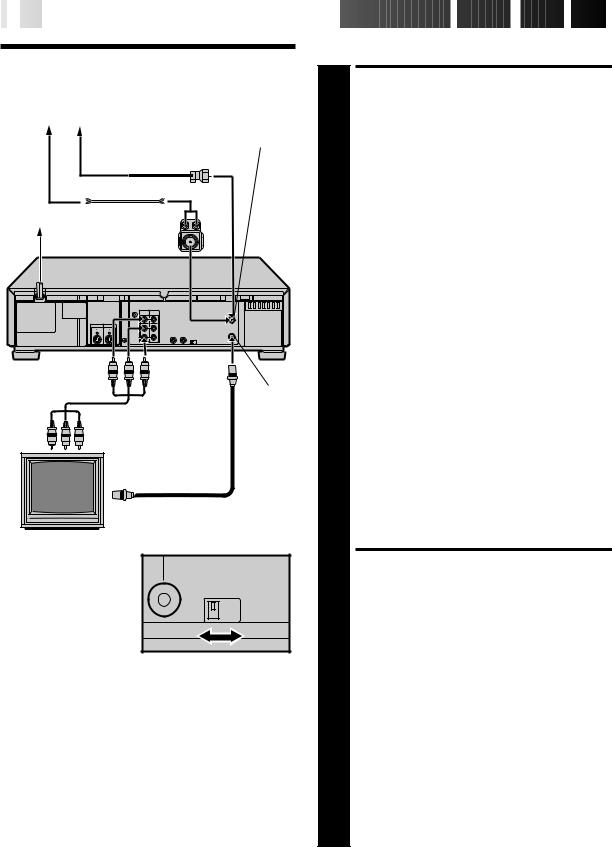
Connections
Antenna or Cable
ANTENNA IN
(Antenna or Cable input)
|
Coaxial Cable |
|
|
Flat Feeder |
|
AC Outlet |
Matching |
|
AC Power |
Transformer |
|
(Not supplied) |
||
Cord |
||
|
Back of VCR
TV OUT
Audio/Video Cable (supplied)
RF Cable (supplied)
75 ohm terminal
TV
Back of VCR
 CH3 CH4
NOTES:
cThe VCR channel is the channel on the TV which will display the audio and video signals from the VCR. The VCR's CH3CH4 switch, on the back of the VCR, sets the VCR channel to CH3 or CH4.
cThe CH3–CH4 switch is preset to the CH3 position.
Set to CH4 if CH3 is used for broadcasting in your area and set the channel on the TV to correspond to the VCR's CH3– CH4 switch setting.
cIf you have connected your VCR to the TV using the RF connector, you may need to press the TV's CH UP and then CH DOWN when switching between the TV and VCR input modes, to maintain good picture quality.
cEven if you are using AV cables to connect your VCR to your TV, you must also connect it using the RF cable. This will ensure that you can record one show while watching another (Z pg. 40).
cFor full identification of the VCR's rear panel, refer to the Index (REAR VIEW Z pg. 71).
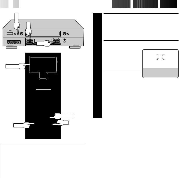
Basic Connections
|
CHECK CONTENTS |
|
Make sure the package contains all of the accessories |
1 listed in “SPECIFICATIONS” (Z pg. 73). |
|
|
SITUATE VCR |
2 Place the VCR on a stable, horizontal surface. |
|
3 |
CONNECT VCR TO TV |
The connection method you use depends on the type of |
|
TV you have. |
|
|
|
RF Connection |
|
|
c To Connect To A TV With NO AV Input Terminals . . . |
|
a– Disconnect the TV antenna from the TV. |
|
b– Connect the TV antenna cable to the ANTENNA |
|
IN jack on the rear of the VCR. |
|
c– Connect the supplied RF cable between the TV |
|
OUT jack on the rear of the VCR and the TV’s |
|
antenna terminal. Set TV on CH3 or CH4 |
|
corresponding to the CH3 – CH4 switch setting on |
|
the back of the VCR. |
AV Connection
cTo Connect To A TV With AV Input Terminals . . .
a– Connect the antenna, VCR and TV as shown in the illustration.
b– Connect an Audio/Video Cable between the AUDIO OUT and VIDEO OUT jacks on the rear of the VCR and the AV IN jacks on the TV. Set your TV in video input mode or A/V input mode. Refer to the TV Instruction Manual.
S-VIDEO Connection
cIf you have a TV with S-VIDEO input terminals, see "S-VIDEO Connection" on page 7.
|
CONNECT VCR TO |
4 |
POWER SOURCE |
Connect the power plug to an AC outlet. |
|
|
|
c The clock and tuner channels will automatically be |
|
set when the antenna is connected and when the AC |
|
|
is first connected to the VCR (Z pg. 8). |
|
(If "Auto" or "CH" is displayed on the front display |
|
panel before the VCR is powered on, the clock and |
|
tuner channels are being set automatically. Wait for |
|
the time to be displayed on the front display panel |
|
before powering on the VCR.) |
|
|
|
FINAL PREPARATION FOR |
|
USE |
|
Power on the VCR and if you have connected the VCR |
|
to the TV using the RF connector, select the VCR |
5 channel (3 or 4) by setting the switch on the rear of the |
|
|
VCR as shown in the illustration. |
|
You can now perform simple playback (Z pg. 22) or |
|
simple recording (Z pg. 23). |


 EN
EN
 7
7
ANTENNA IN
(Antenna or Cable input)
Antenna or Cable
Coaxial Cable
Flat Feeder
Matching Transformer (not supplied)
Back of VCR
AC Power
Cord
 JLIP
JLIP
|
OUT IN |
|
ANTENNA |
IN |
|
VIDEO |
|
|
|
S VIDEO |
REMOTE AV |
|
|
|
|
(MONO) |
|
|
|
OUT |
IN |
PAUSE COMPULINK |
VHF/UHF |
|
|
L |
|
TV |
|
|
AUDIO |
CABLE |
OUT |
|
|
|
|
||
BOX
R |
CH3 CH4 |
|
AC Outlet |
S VIDEO OUT |
TV OUT |
|
||
|
S-Video Cable |
|
|
(supplied) |
Audio/Video Cable |
|
|
(supplied) |
|
S VIDEO IN |
RF Cable (supplied) |
|
|
75 ohm terminal
TV
NOTES:
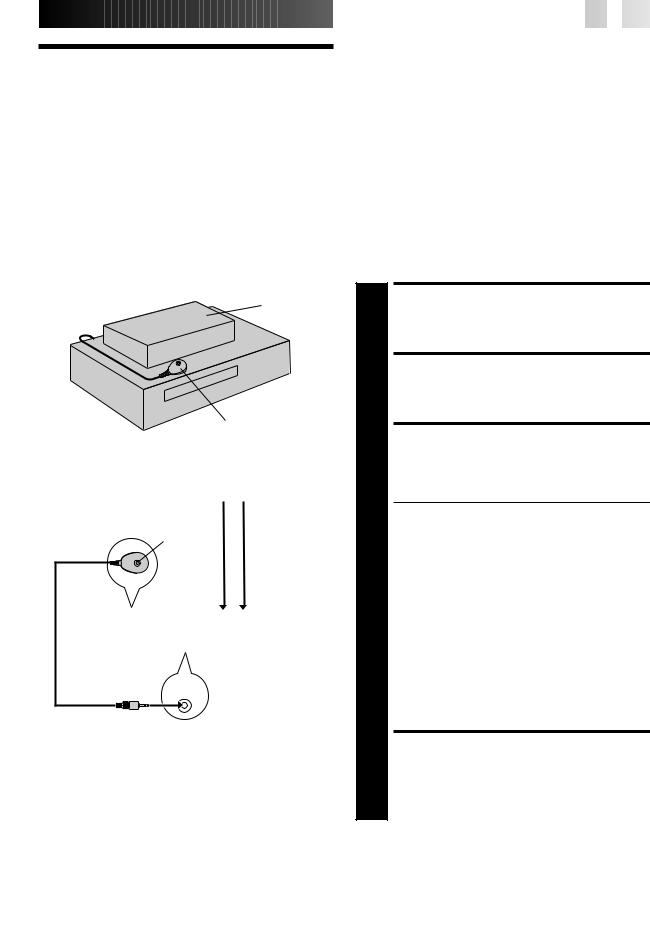
cTo make the most of the Super VHS picture performance we recommend that you use the supplied S-VIDEO cable to connect your VCR to a TV with an S-VIDEO input connector.
cTo operate the VCR with your TV using the S-VIDEO connection, set your TV to the AV mode using the TV's remote control.
You can also use the TV/VCR button on the VCR's remote control to set your TV to the AV mode. (Z pg. 60)
S-VIDEO Connection
CONNECT VCR TO TV
a– Connect both the RF cable and the AV cables to the TV as explained in step 3 of "Basic Connections" (Z pg. 6).
b– Connect the S-Video cable between the S-VIDEO OUT jack on the rear of the VCR and the S-VIDEO IN jack on the TV.
8

 EN
EN


 INITIAL

 SETTINGS

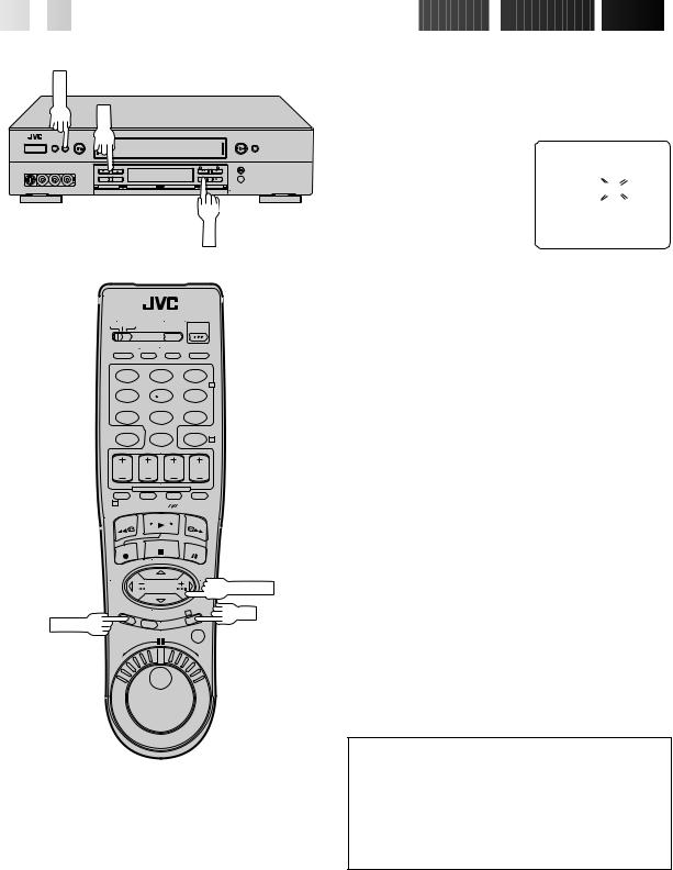
Plug & Play
Auto Clock Set/Auto Tuner Set
ATTENTION
If you use a cable box, Plug & Play will not function; set the clock and tuner channels manually. (Z pg.11 – 15)
IMPORTANT
cDon’t press any buttons on the VCR or remote while Plug & Play is in progress.
cIf you perform Plug & Play successfully, there’s no need to perform the Clock (Z pg. 11) and Tuner (Z pg. 14) procedures. If, however, you want to add or delete channels, refer to “Add Or Delete A Channel” on page 15.
The Plug & Play function sets the clock and tuner channels automatically when power is first connected to the VCR. The antenna cable must be connected for the Plug & Play function.
The time and date can be set automatically from clock setting data that is transmitted by one of the regular TV broadcast channels. We call this TV channel the “Host Channel” and it is a PBS channel in your area.
PLUG & PLAY SETUP
1 Connect the antenna cable to the VCR (Z pg. 6). Then connect the VCR’s power plug to an AC outlet. Do not power on the VCR. The clock and tuner channels will be set automatically.
NOTES:
cAuto clock set is performed first. The auto clock set function scans all the channels received by your VCR to find the Host Channel and then sets the clock. "Auto" blinks on the front display panel during Auto clock set.
cAuto channel set is performed next. The auto channel set function scans all the channels that are receivable by your VCR. It then automatically assigns each receivable channels to the CH5 (+/–) buttons. It skips non-receivable channels. During auto channel set the channel numbers are displayed as they are scanned and set.
cWhen Plug & Play has been completed successfully the correct time is displayed.
cIf an incorrect time or "– –:– –" appears on the display panel, see "What To Do If Plug & Play Has Failed" on next page.
|
|
|
|
|
|
|
|
|
|
|
|
|
|
|
|
During Initial Auto Clock Set |
During Auto Channel Set |
Plug & Play Completed |
|||||
"Auto" blinks. |
The channel numbers are displayed |
The current time (including |
|||||
|
|
|
as they are scanned and set. |
AM/PM) is displayed. |
|||
|
|
|
|
|
|
|
|
* If an incorrect time or "– –:– –" appears on the display panel, see "What To Do If Plug & Play Has Failed" on next page.


 EN
EN
 9
9
INFORMATION
cIf "AUTO CLOCK" is set to "ON" at the Clock Set screen on page 12, the clock will be adjusted automatically by the host channel every hour on the hour (except for 11:00 PM, midnight, 1:00 AM and 2:00 AM) by the incoming PBS channel clock setting data. (This automatic clock adjustment can only be performed when the VCR’s power is turned off. The clock will be adjusted on the hour based on the time displayed on the VCR, not on the actual real time.) The default setting of "AUTO CLOCK" is "ON".
cIf the memory backup fails, because of a power outage or because the AC was removed from the VCR, Plug & Play will be performed when power is restored to the VCR.
What To Do If Plug & Play Has Failed
cIf an incorrect time is displayed on the front display panel, you may be receiving the clock setting data of a PBS channel from an adjacent time zone, or an incorrect PBS channel from a cable TV system. In this case, perform the Semi-Auto (Z pg. 12) or Manual Clock Set (Z pg. 13) procedure. Auto channel set has already taken place and it need not be set again.
cIf “- -:- -” appears on the display, your antenna cable may not be connected to the VCR or there may not be a Host PBS signal available in your area. Ensure that the antenna cable is connected correctly. Then power on and power off the VCR; the Plug &
Play function will be automatically reactivated and "Auto" will be displayed on the VCR's front panel. If Plug & Play is not performed but the antenna cable is connected correctly, perform the Manual Clock Set procedure (Z pg. 13). Auto channel set has not yet taken place, so please also perform the “Set Receivable Channels” procedure (Z pg. 14).
10

 EN
EN


 INITIAL
 SETTINGS
 (cont.)

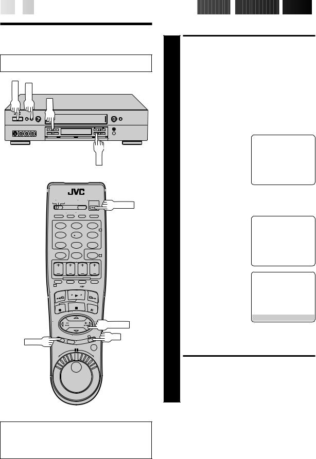
Language
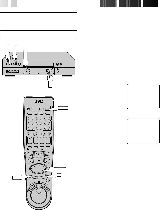
Turn on the TV and select the VCR channel 3 or 4 (or AV mode).
POWER |
MENU |
5 |
|
|
CH |
OK
POWER
1 |
2 |
3 |
|
|
2 |
4 |
5 |
6 |
7 |
8 |
9 |
|
0 |
4 |
1
 TIME SCAN
3 |
OK |
MENU
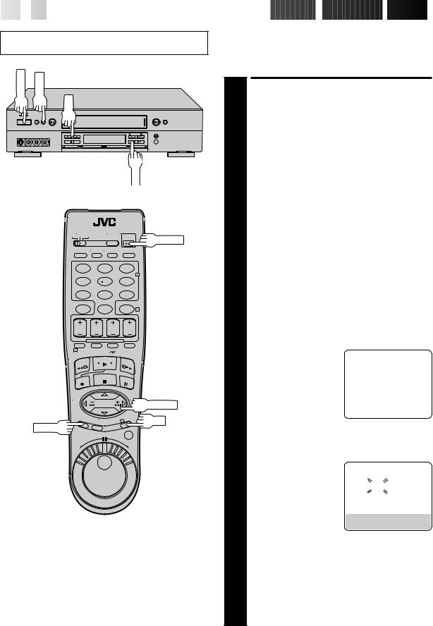
This VCR offers you the choice to view on-screen messages in English, Spanish or French (not including messages superimposed on the TV picture). Select the desired language using this procedure. The default setting is "ENGLISH".
|
1 |
|
TURN ON THE VCR |
|||||
|
|
Press POWER. |
|
|
|
|
|
|
|
|
|
ACCESS MAIN MENU |
|||||
|
2 |
|
SCREEN |
|
|
|
|
|
|
|
Press MENU. |
|
|
|
|
|
|
|
|
|
ACCESS INITIAL SET |
|||||
|
3 |
|
SCREEN |
|
|
|
|
|
|
|
At the Main Menu screen, |
|
MAIN MENU |
||||
|
|
move the highlight bar |
|
FUNCTION SET |
||||
|
|
(arrow) to “INITIAL SET” by |
|
|||||
|
|
|
TUNER SET |
|||||
|
|
|
pressing CH5 or TIME |
|
|
|
|
|
|
|
|
|
=INITIAL SET |
||||
|
|
SCAN %fi, then press OK |
|
HI-FI REC LEVEL CTL |
||||
|
|
or TIME SCAN%. |
|
|
|
|
|
|
|
|
|
|
|
|
|
|
|
|
|
|
|
|
PRESS (5, ), THEN (OK) |
|||
|
|
|
|
|
PRESS (MENU) TO END |
|
||
|
|
|
|
|
|
|
|
|
|
4 |
|
SELECT LANGUAGE |
|||||
|
|
Move the highlight bar |
|
INITIAL SET |
||||
|
|
(arrow) to "LANGUAGE" |
|
|||||
|
|
|
|
|
|
|
||
|
|
by pressing CH 5 or |
|
CLOCK SET |
||||
|
|
|
=LANGUAGE ENGLISH |
|
||||
|
|
|
TIME SCAN %fi, then |
|
GUIDE CHANNEL SET |
|
||
|
|
|
press OK or TIME SCAN% |
|
CABLE BOX SET |
|||
|
|
|
to select the desired |
|
DBS RECEIVER SET |
|||
|
|
|
language. |
|
JLIP ID NO. SET |
|||
|
|
|
|
SELECT WITH (5, ) AND (OK) |
||||
|
|
|
|
|
||||
|
|
|
|
|
PRESS (MENU) TO END |
|||
|
|
|
|
|
|
|
|
|
|
|
|
RETURN TO NORMAL |
|||||
|
5 |
|
SCREEN |
|
|
|
|
|
|
|
Press MENU. |
|
|
|
|
|
|


 EN
EN
 11
11
Clock
Turn on the TV and select the VCR channel 3 or 4 (or AV mode).
POWER |
MENU |
CH
OK
POWER
1 |
2 |
3 |
|
|
2 |
4 |
5 |
6 |
7 |
8 |
9 |
|
0 |
4 |
1
 TIME SCAN
3 |
OK |
MENU
Perform clock setting only if the clock has not been set correctly by the Plug & Play function or you use a cable box. Access the Clock Set screen to perform the Semi-Auto or Manual clock setting procedure. Each procedure starts from step 5.
If you use a cable box, set the clock manually. (Z pg. 13)
Preparation
1 |
|
TURN ON THE VCR |
||||||
|
Press POWER. |
|
|
|
|
|
||
|
|
ACCESS MAIN MENU |
||||||
2 |
|
SCREEN |
|
|
|
|
|
|
|
Press MENU. |
|
|
|
|
|
||
|
|
ACCESS INITIAL SET |
||||||
3 |
|
SCREEN |
|
|
|
|
|
|
|
At the Main Menu screen, |
|
MAIN MENU |
|||||
|
move the highlight bar |
|
||||||
|
|
FUNCTION SET |
||||||
|
(arrow) to “INITIAL SET” by |
|
||||||
|
|
TUNER SET |
||||||
|
|
pressing CH5 or TIME |
|
|
|
|
||
|
|
|
=INITIAL SET |
|||||
|
SCAN %fi, then press OK |
|
HI-FI REC LEVEL CTL |
|||||
|
or TIME SCAN%. |
|
|
|
|
|
||
|
|
|
|
|
|
|
|
|
|
|
|
|
|
PRESS (5, ), THEN (OK) |
|||
|
|
|
|
|
PRESS (MENU) TO END |
|
||
|
|
|
|
|
|
|
|
|
|
|
ACCESS CLOCK SET |
||||||
4 |
|
SCREEN |
|
|
|
|
|
|
|
Move the highlight bar |
|
INITIAL SET |
|||||
|
(arrow) at the Initial Set |
|
||||||
|
|
|
|
|
|
|||
|
screen to “CLOCK SET” by |
|
=CLOCK SET |
ENGLISH |
||||
|
|
LANGUAGE |
||||||
|
|
pressing TIME SCAN %fi, |
|
GUIDE CHANNEL SET |
||||
|
then press OK or TIME |
|
CABLE BOX SET |
|||||
|
% |
|
|
DBS RECEIVER SET |
||||
|
SCAN . |
|
JLIP ID NO. SET |
|||||
|
|
c "CABLE BOX USERS SET |
|
|
SELECT WITH (5, ) AND (OK) |
|||
|
|
|
PRESS (MENU) TO END |
|||||
|
|
CLOCK MANUALLY" |
|
|||||
|
|
|
|
|
|
|
||
|
|
appears on the screen for about 5 seconds, then the |
||||||
|
|
Clock Set screen appears. |
|
|
|
|
|
|
12

 EN
EN


 INITIAL
 SETTINGS
 (cont.)

CH
MENU
OK
1 |
2 |
3 |
|
|
2 |
4 |
5 |
6 |
7 |
8 |
9 |
|
0 |
4 |
1
 TIME SCAN
3 |
OK |
MENU
Semi-Auto
You can change the Host Channel/D.S.T. /Time Zone setting manually.
|
5 |
|
SET AUTO CLOCK TO ON |
||||||
|
|
At the Clock Set screen, |
|
CLOCK SET |
|
|
|||
|
|
press OK or TIME SCAN% |
|
|
|
||||
|
|
|
TIME |
DATE YEAR |
|||||
|
|
repeatedly to move the |
|
||||||
|
|
|
1:00PM |
12/24 |
|
98 THU |
|||
|
|
|
highlight bar to "AUTO |
|
|
|
|
|
|
|
|
|
|
AUTO CLOCK : ON |
|
|
|||
|
|
|
CLOCK" and press CH 5 |
|
HOST CH |
: AUTO |
(CATV) |
||
|
|
|
or TIME SCAN %fito set |
|
D.S.T. |
: AUTO |
|
|
|
|
|
|
to "ON". |
|
TIME ZONE |
: AUTO |
|
|
|
|
|
|
|
PRESS (5, ), THEN (OK) |
|
||||
|
|
|
a– To select the Host |
|
|
||||
|
|
|
|
PRESS (MENU) TO END |
|
||||
|
|
|
Channel — go to step 6 |
|
|
|
|
|
|
|
|
|
b– To select the D.S.T. mode — go to step 7 |
|
|
||||
|
|
|
c– To select the Time Zone — go to step 8 |
|
|
||||
|
|
|
NOTE: |
|
|
|
|
|
|
|
|
|
The time that has been set previously will be erased |
||||||
|
|
|
when "AUTO CLOCK", "HOST CH", "D.S.T." or "TIME |
||||||
|
|
|
ZONE" setting is changed. |
|
|
|
|
|
|
|
|
|
|
|
|
|
|||
|
6 |
|
SELECT HOST CHANNEL |
||||||
|
|
You can either select "AUTO" or enter a PBS channel |
|||||||
|
|
number. Move the highlight bar to "HOST CH" by |
|||||||
|
|
pressing OK or TIME SCAN%, then press CH 5 or |
|||||||
|
|
TIME SCAN %fito set to "AUTO" or the desired PBS |
|||||||
|
|
channel number. |
|
|
|
|
|
|
|
|
|
|
NOTE: |
|
|
|
|
|
|
|
|
|
There are some PBS channels that do not transmit clock |
||||||
|
|
|
setting data. |
|
|
|
|
|
|
|
|
|
|
|
|
|
|
||
|
7 |
|
SELECT D.S.T. MODE |
|
|
||||
|
|
You have three choices: |
|
|
|
|
|
|
|
|
|
a– Select "AUTO" and the adjustment to your VCR's |
|||||||
|
|
clock will be made according to the incoming signal |
|||||||
|
|
|
from the host channel. |
|
|
|
|
|
|
|
|
|
b– Select "ON" and the adjustment will be made based |
||||||
|
|
|
on the clock itself. |
|
|
|
|
|
|
|
|
|
c– Select "OFF" if Daylight Saving Time does not apply |
||||||
|
|
|
to you. |
|
|
|
|
|
|
|
|
|
Move the highlight bar to "D.S.T." by pressing OK or |
||||||
|
|
|
TIME SCAN%, then press CH 5 or TIME SCAN %fi |
||||||
|
|
to select the desired mode. |
|
|
|
|
|
|
|
**AUTO DAYLIGHT SAVING TIME
This function enables automatic adjustment of the VCR’s clock at the start and end of Daylight Saving Time.
With Auto DST activated, . . .
. . . on the first Sunday of April at 2:00 AM, the clock is adjusted to 3:00 AM.
. . . on the last Sunday of October at 2:00 AM, the clock is adjusted to 1:00 AM.

|
|
|
|
|
|
|
|
|
SELECT TIME ZONE |
||
|
You can select the time zone automatically or manually. |
||
|
Move the highlight bar to "TIME ZONE" by pressing OK |
||
8 or TIME SCAN%, then press CH 5 or TIME SCAN %fi |
|||
|
to select "AUTO" or the desired time zone. |
||
|
AUTO |
ATLANTIC |
|
|
HAWAII |
EASTERN |
|
|
ALASKA |
CENTRAL |
|
|
PACIFIC |
MOUNTAIN |
|
NOTE:
If an incorrect time is displayed by the Plug & Play function, you may be receiving the clock setting data of a PBS channel from an adjacent time zone or from an incorrect PBS channel from a cable TV system. If you selected "AUTO" for the host channel in step 6, be sure to select the correct time zone manually.
RETURN TO NORMAL SCREEN
9 Press MENU.
IMPORTANT
Turn the VCR off after performing the Semi-Auto Clock Set procedure. "Auto" will appear on the front display panel when the clock is being set. The current time will appear automatically when the clock is set.


 EN
EN
 13
13
Manual
SET TIME
5 Press CH 5 or TIME SCAN %fiuntil the desired time appears, then press
OK or TIME SCAN %.
c Press and hold CH 5 or TIME SCAN %fi to change the time by 30minute increments.
cWhen the time is entered manually, "AUTO CLOCK" will be automatically set to "OFF", and "HOST CH" and "TIME ZONE" will disappear.
SET DATE
6 Press CH 5 or TIME SCAN %fi until the desired date appears, then press OK or TIME SCAN %.
cPress and hold CH 5 or TIME SCAN %fi to change the date by 15-day increments.
SET YEAR
7 Press CH 5 or TIME SCAN %fiuntil the desired year appears, then press OK or TIME SCAN %twice.
SELECT D.S.T. MODE
8 Press CH 5 or TIME SCAN %fi to select the desired mode.
a– Set to "ON" so that the adjustment to your VCR's clock will be made on the clock itself.
b– Set to "OFF" if Daylight Saving Time does not apply to you.
START CLOCK
9 Press MENU and normal screen appears.
To Make Corrections
Press OK or TIME SCAN %until the item you want to change blinks, then press CH 5 or TIME SCAN %fi.
14

 EN
EN


 INITIAL
 SETTINGS
 (cont.)

Tuner
Turn on the TV and select the VCR channel 3 or 4 (or AV mode).
POWER |
MENU |
CH
OK
POWER
1 |
2 |
3 |
|
|
2 |
4 |
5 |
6 |
7 |
8 |
9 |
|
0 |
4 |
|
|
1
 TIME SCAN
3 |
OK |
MENU
Set Receivable Channels
|
TURN ON THE VCR |
|
|
|
||||
1 Press POWER. |
|
|
|
|
|
|
|
|
|
ACCESS MAIN MENU |
|
|
|
||||
|
SCREEN |
|
|
|
|
|
|
|
2 Press MENU. |
|
|
|
|
|
|
|
|
|
ACCESS TUNER SET SCREEN |
|||||||
|
Move the highlight bar |
|
MAIN MENU |
|
|
|
||
|
(arrow) to "TUNER SET" by |
|
|
|
|
|
|
|
3 pressing CH5 or TIME |
|
FUNCTION SET |
|
|
|
|||
|
=TUNER SET |
|
|
|
|
|
||
SCAN %fi, then press OK |
|
INITIAL SET |
|
|
|
|
|
|
or TIME SCAN%. |
|
HI-FI REC LEVEL CTL |
|
|
|
|||
|
|
|
|
|
|
|
|
|
|
|
|
PRESS (5, ), THEN (OK) |
|||||
|
|
|
PRESS (MENU) TO END |
|
|
|
||
|
|
|
|
|
|
|
|
|
|
PERFORM AUTO CHANNEL |
|||||||
|
SET |
|
|
|
|
|
|
|
|
Move the highlight bar |
|
TUNER SET |
|
|
|
||
|
(arrow) to "AUTO CHAN- |
|
|
|
|
|
|
|
4 NEL SET" by pressing |
|
BAND |
CATV |
|||||
|
=AUTO CHANNEL SET |
|
|
|
|
|||
|
CH5 or TIME SCAN |
|
MANUAL CHANNEL SET |
|||||
|
%fi, then press OK or |
|
|
|
|
|
|
|
TIME SCAN%. |
|
|
|
|
|
|
|
|
|
|
|
|
|
|
|||
|
c Receivable channels in |
|
SELECT WITH (5, ) AND (OK) |
|||||
|
|
PRESS (MENU) TO END |
|
|
|
|||
|
your area are |
|
|
|
|
|
|
|
|
automatically assigned to |
|
AUTO CHANNEL SET |
|||||
|
the CH5 (+/–) buttons, |
|
||||||
|
|
|
|
|
|
|
|
|
|
and non-receivable |
|
|
|
|
|
|
|
|
channels are skipped. |
|
SCANNING |
|
|
|
||
|
|
|
|
|
|
|||
NOTES:
c At the end of Auto Channel Set, “SCAN COMPLETED” appears on screen.
cIf the scan was unsuccessful, “SCAN COMPLETED– NO SIGNAL” appears on screen. Check the connections and start again.
RETURN TO NORMAL SCREEN
5 Press MENU.
INFORMATION
The VCR detects the band (TV or CATV) and selects the correct band automatically during Auto Channel Set. The selected band will be displayed on the right side of "BAND" on the Tuner Set screen.

CH
MENU
OK
|
1 |
2 |
3 |
|
|
|
2 |
NUMBER |
4 |
5 |
6 |
|
|
|
|
|
7 |
8 |
9 |
|
|
0 |
4 |
|
1 |
|
|
 TIME SCAN
3 |
OK |
MENU


 EN
EN
 15
15
Add Or Delete A Channel
|
|
ACCESS MAIN MENU |
|
|
|
|
||||
1 |
|
SCREEN |
|
|
|
|
|
|
|
|
|
Press MENU. |
|
|
|
|
|
|
|
|
|
2 |
|
ACCESS TUNER SET SCREEN |
||||||||
|
Move the highlight bar (arrow) to "TUNER SET" by |
|||||||||
|
pressing CH5 or TIME SCAN %fi, then press OK or |
|||||||||
TIME SCAN%. |
|
|
|
|
|
|
|
|
||
|
|
ACCESS MANUAL |
|
|
|
|
||||
3 |
|
CHANNEL SET SCREEN |
|
|
|
|
||||
|
Move the highlight bar |
|
|
TUNER SET |
|
|
|
|
||
|
(arrow) to "MANUAL |
|
|
|
|
|
|
|||
|
|
BAND |
CATV |
|||||||
|
CHANNEL SET" by |
|
||||||||
|
|
AUTO CHANNEL SET |
|
|
|
|
||||
|
|
pressing CH5 or TIME |
|
|
|
|
|
|
||
|
|
|
=MANUAL CHANNEL SET |
|||||||
|
SCAN %fi, then press OK |
|
|
|
|
|
|
|
|
|
|
or TIME SCAN%. |
|
|
|
|
|
|
|
|
|
|
|
|
|
|
|
|
|
|
|
|
|
|
|
|
SELECT WITH (5, ) AND (OK) |
||||||
|
|
|
|
PRESS (MENU) TO END |
|
|
|
|
||
|
|
|
|
|
|
|
|
|
|
|
|
|
ADD OR SKIP DESIRED |
|
|
|
|
||||
4 |
|
CHANNEL |
|
|
|
|
|
|
|
|
|
Input the channel number |
|
MANUAL CHANNEL SET |
|||||||
|
using the NUMBER keys or |
|
|
|
|
|
|
|
|
|
|
by pressing CH5 or |
|
|
(CATV) |
|
|
|
|
||
|
TIME SCAN %fi, then |
|
|
|
|
|
|
|
|
|
|
|
|
CH 45 ADD |
|
|
|
|
|||
|
press OK or TIME SCAN% |
|
|
|
|
|
|
|
|
|
|
to set to "ADD" or "SKIP" |
|
|
|
|
|
|
|
|
|
|
|
PRESS NUMBER KEY (0–9) |
|
|
||||||
|
as required. Repeat for |
|
|
|||||||
|
|
OR (5, ), THEN (OK) |
|
|||||||
|
each channel you want to |
|
PRESS (MENU) TO END |
|
|
|
|
|||
|
add or skip. |
|
|
|
|
|
|
|
|
|
|
|
|
|
|
|
|
|
|
|
|
|
|
RETURN TO NORMAL |
|
|
|
|
||||
5 |
|
SCREEN |
|
|
|
|
|
|
|
|
|
Press MENU. |
|
|
|
|
|
|
|
|
|
16

 EN
EN


 INITIAL
 SETTINGS
 (cont.)

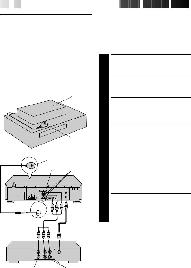
Cable Box
Control
Suggested Location
Place the cable box on top of the VCR. Attach the VCR's Controller to the top of the VCR with the Controller’s transmitter pointed towards the cable box’s remote sensor.
ATTENTION:
The Controller can also control a DBS receiver. If both a cable box and a DBS receiver are used, position the controller so its signal reaches the remote control sensors of both the cable box and DBS receiver.
Cable box
Controller
Your VCR (suggested
locations)
Controller
Transmitter
Your VCR |
VIDEO IN AUDIO IN
CABLE |
Connected to |
BOX |
ANTENNA IN |
|
Audio/Video cable (supplied)
Cable box
VIDEO OUT |
AUDIO OUT |
This procedure is required if you receive your TV channels through a cable box (descrambler). The Controller allows the VCR to automatically switch the cable box channel during timer-recording. The Controller is effective for recording shows that have been programmed using VCR Plus+ (Z pg. 46) or Express Timer Programming (Z pg. 50).
Situate And Connect
Controller
SITUATE CONTROLLER
1 Place the Controller so that the path between its transmitter and the cable box’s remote sensor is unobstructed.
ATTACH CONTROLLER
2 Fasten securely using the supplied adhesive strip.
CONNECT CABLE BOX TO VCR
3 The connection method depends on the type of cable box you have.
If your cable box has AUDIO and VIDEO OUT connectors . . .
. . . connect them to the AUDIO and VIDEO IN connectors on your VCR. Set the VCR to channel "L-1" for the rear AUDIO and VIDEO IN connectors, or channel "F-1" for the front AUDIO and VIDEO IN connectors to use the cable box.
If your cable box doesn’t have AUDIO and VIDEO OUT connectors . . .
. . . connect the antenna output connector on the cable box to the ANTENNA IN connector on the rear of your VCR.
Set the VCR tuner to the same channel as the cable box RF output (see page 17 also).
NOTE:
When connecting your cable box refer to its instruction manual.
CONNECT CONTROLLER TO VCR
4 Connect to the CABLE BOX connector on your VCR.
About Your Cable Box
This VCR has two separate methods to control your Cable Box.
cThe VCR's Wireless Remote Control Unit can control your Cable Box.
This eliminates the need for a separate Cable Box Remote Control Unit.
cThe VCR's Controller can also control your Cable Box.
This allows the VCR to change your Cable Box's channel number during timer recording.
Each method must be set up separately. To set up the VCR's Remote Control unit, refer to page 61. To set up the Controller go to page 17.
Turn on the TV and select the VCR channel 3 or 4 (or AV mode).
POWER |
MENU |
CH
OK
POWER
1 |
2 |
3 |
|
|
2 |
4 |
5 |
6 |
7 |
8 |
9 |
|
0 |
4 |
1
 TIME SCAN
3 |
OK |
MENU


 EN
EN
 17
17
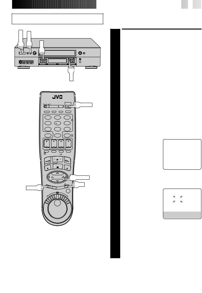
Set Cable Box Output
Channel & Cable Box Brand
|
TURN ON CABLE BOX |
||||||
|
Select a channel other than channel 9 on your cable |
||||||
1 box. |
|
|
|
|
|
|
|
|
TURN ON THE VCR |
||||||
2 Press POWER. |
|
|
|
|
|
|
|
|
ACCESS MAIN MENU |
||||||
|
SCREEN |
|
|
|
|
|
|
3 Press MENU. |
|
|
|
|
|
|
|
|
ACCESS INITIAL SET SCREEN |
||||||
|
Press CH5 or TIME SCAN %fi to move the highlight |
||||||
bar (arrow) to “INITIAL SET”, then press OK or TIME |
|||||||
4 SCAN%. |
|
|
|
|
|
|
|
|
ACCESS CABLE BOX SET |
||||||
|
SCREEN |
|
|
|
|
|
|
|
Press CH5 or TIME |
|
|
INITIAL SET |
|||
|
SCAN %fito move the |
|
CLOCK SET |
||||
5 highlight bar (arrow) to |
|
||||||
|
LANGUAGE ENGLISH |
||||||
|
“CABLE BOX SET”, then |
|
GUIDE CHANNEL SET |
||||
|
press OK or TIME SCAN%. |
|
=CABLE BOX SET |
SET |
|||
|
|
|
DBS RECEIVER |
||||
|
|
|
JLIP ID NO. SET |
||||
|
|
|
SELECT WITH (5, ) AND (OK) |
|
|||
|
|
|
PRESS (MENU) TO END |
|
|||
|
|
|
|
|
|
|
|
|
SELECT CABLE BOX |
||||||
|
OUTPUT CHANNEL |
||||||
|
Your selection depends on |
|
CABLE BOX SET |
||||
|
how your cable box is |
|
|
|
|
|
|
6 connected to your VCR. |
|
|
|
||||
|
|
OFF |
|
||||
|
|
|
|
|
|
|
|
If your cable box is connected to your VCR using an RF connection . . .
. . . press CH 5 or TIME SCAN %fiuntil the
channel number representing the cable box’s output (CH2 – CH9) appears on the screen.
If your cable box is connected to your VCR's FRONT AUDIO/VIDEO IN connectors . . .
. . . press CH 5 or TIME SCAN %fi until "ON F-1 (FRONT)" appears on the screen.
If your cable box is connected to your VCR’s REAR AUDIO/VIDEO IN connectors . . .
. . . press CH 5 or TIME SCAN %fi until "ON L-1 (REAR)" appears on the screen.
CONTINUED ON NEXT PAGE
18

 EN
EN


 INITIAL
 SETTINGS
 (cont.)

CH
MENU
OK
|
1 |
2 |
3 |
|
|
|
2 |
NUMBER |
4 |
5 |
6 |
|
|
|
|
|
7 |
8 |
9 |
|
|
0 |
4 |
|
1 |
|
|
 TIME SCAN
3 |
OK |
MENU
INFORMATION
When the VCR's clock has not been set (with AUTO CLOCK set to ON), if you press OK in step 7, "CABLE BOX USERS SET CLOCK MANUALLY" will be displayed on the screen for about 5 seconds, then the Clock Set screen will appear; perform the manual clock setting procedure on page 13. If you press MENU after the clock has been set, the Cable Box Brand Set screen appears.
NOTES:
cAlthough the supplied Controller is compatible with many different cable box brands, it is possible that it will not work with your cable box.
cIf your cable box doesn’t respond to any code between 1 and 25, you can’t use the Controller to change cable box channels. In this case, make sure to leave the cable box turned on and tuned to the proper channel before the scheduled start of timer recording.
Please contact your cable company about the possibility of exchanging your current cable box with one that is compatible with your VCR.
cThe VCR can only change the cable box channel through the Controller during timer recording.
cIf your cable box is one that can’t be operated with a remote control (because it has no remote sensor), you can’t use the Controller to change its channels. Make sure to leave the cable box turned on and tuned to the proper channel before the scheduled start of timer recording.
cIf the VCR's memory backup expires because of a power failure, set the cable box output channel and brand again.
cIf you are unable to set the Controller, please contact JVC toll free at 1-800-252-5722.
ACCESS CABLE BOX BRAND SET SCREEN
7 Press OK.
ENTER CABLE BOX BRAND
8 |
Press the appropriate |
CABLE BOX BRAND SET |
|||
NUMBER keys to enter the |
|||||
|
|
|
|||
Cable Box Code from the |
|
1 |
|
||
|
CABLE BOX BRAND LIST |
|
|
|
|
|
shown below, then press |
|
|
|
|
|
OK. |
|
|
|
|
c If the cable box’s channel changes to 9,
setting is complete. Press OK and "CABLE BOX CONTROL IS ON" appears on the screen for about 5 seconds, then it returns to the normal screen.
cIf the cable box's channel does not change to 9, press CH 5 or TIME SCAN %fito move the highlight bar (arrow) to "NO", then press OK. By entering another code, repeat step 8 until the cable box’s channel changes to 9.
cIf the channel does not change after going through all the code numbers listed for your model of cable box, then try all the other numbers between 1 and 25.
CABLE BOX BRAND LIST
BRAND |
CODE |
|
|
ARCHER |
1, 5, 17 |
CABLETENNA |
1, 17 |
CABLEVIEW |
15, 16, 17, 21, 25 |
CITIZEN |
15, 16, 17, 21, 25 |
CURTIS |
2 |
DIAMOND |
1, 17 |
EASTERN |
19 |
GC BRAND |
15, 16, 17, 21, 25 |
GEMINI |
15 |
GENERAL INSTRUMENTS |
1, 4, 6, 11, 12, 15 |
HAMLIN |
10, 18, 19, 23 |
JASCO |
15 |
JERROLD |
1, 4, 6, 11, 12, 15 |
NOVAVISION |
2 |
OAK |
7, 20 |
PANASONIC |
13, 14 |
PULSER |
15, 16, 17, 21, 25 |
RCA |
13, 14 |
REGAL |
10, 18, 19, 23 |
REGENCY |
19 |
REMBRANDT |
1, 16, 17 |
SAMSUNG |
5, 16, 24 |
SCIENTIFIC ATLANTA |
2 |
SIGMA |
7, 20 |
SL MARX |
5, 16, 17, 24, 25 |
SPRUCER |
13, 14 |
STARGATE |
5, 15, 16, 17, 21, 24, 25 |
TELEVIEW |
5, 16, 24 |
TOCOM |
1, 4, 16 |
UNIKA |
1, 17 |
UNIVERSAL |
16, 17, 25 |
VIDEOWAY |
3, 9, 22 |
ZENITH |
3, 9, 22 |
|
|
DBS Receiver
Control
Suggested Location
Place the DBS (Direct Broadcast Satellite) receiver on top of the VCR. Attach the VCR's Controller to the top of the VCR with the Controller’s transmitter pointed towards the DBS receiver's remote sensor.
ATTTNTION:
The Controller can also control a cable box. If both a DBS receiver and a cable box are used, position the controller so its signal reaches the remote control sensors of both the DBS receiver and cable box.
DBS receiver
Your VCR |
Controller |
|
|
(suggested locations) |
|
|
DBS receiver |
|
|
|
|
|
|
|
Controller
|
|
Transmitter |
|
|
|
|
|
Connected |
|
|
|
|
||
|
|
|
||
|
|
Connected to |
to VIDEO/ |
|
|
|
ANTENNA IN |
AUDIO IN |
|
|
|
|
|
|
|
|
|
|
|
|
|
|
|
|
|
|
|
|
|
Your VCR
CABLE
BOX
About Your DBS Receiver
This VCR has two separate methods to control your DBS Receiver.
cThe VCR's Wireless Remote Control Unit can control your DBS Receiver.
This eliminates the need for a separate DBS Receiver Remote Control Unit.
cThe VCR's Controller can also control your DBS Receiver. This allows the VCR to change your DBS receiver's channel number during timer recording.
Each method must be set up separately. To set up the VCR's Remote Control unit, refer to page 62. To set up the Controller go to page 20.


 EN
EN
 19
19
The following procedure is required if you receive satellite channels through a DBS (Direct Broadcast Satellite) Receiver. The Controller allows the VCR to automatically switch the DBS Receiver's channels during timer recording.
NOTES:
cThe VCR can automatically change the DBS Receiver channels using the controller when the VCR has been programmed using Express Timer Programming (Z pg. 50).
Because satellite programming does not use PlusCode; the Controller can not change the DBS Receiver channels during VCR Plus+ Timer Recording.
cIf a cable box is also used it is recommended that you connect the DBS receiver to your VCR's A/V inputs and the cable box to your VCR's antenna input.
Situate And Connect
Controller
SITUATE CONTROLLER
1 Place the Controller so that the path between its transmitter and the DBS receiver's remote sensor is unobstructed.
ATTACH CONTROLLER
2 Fasten securely using the supplied adhesive strips.
CONNECT DBS RECEIVER TO VCR
3 The connection method depends on the type of DBS receiver you have.
If your DBS receiver has AUDIO and VIDEO OUT connectors . . .
. . . connect them to the AUDIO and VIDEO IN connectors on your VCR. Set the VCR to channel "L-1" for the rear AUDIO and VIDEO IN connectors, or channel "F-1" for the front AUDIO and VIDEO IN connectors to use the DBS receiver.
If your DBS receiver doesn’t have AUDIO and VIDEO OUT connectors . . .
. . . connect the antenna output connector on the DBS receiver to the ANTENNA IN connector on the rear of your VCR.
Set the VCR's tuner to the same channel as the DBS receiver's RF output. (See page 20 also.)
NOTE:
When connecting your DBS receiver refer to its instruction manual.
CONNECT CONTROLLER TO VCR
4 Connect to the CABLE BOX connector on your VCR.
20

 EN
EN


 INITIAL
 SETTINGS
 (cont.)

Turn on the TV and select the VCR channel 3 or 4 (or AV mode).
POWER |
MENU |
CH
OK
POWER
1 2 3
2
4 5 6
7 8 9
0 4
1
 TIME SCAN
3 |
OK |
MENU
Set DBS Receiver Output
Channel & DBS Receiver
Brand
|
|
TURN ON DBS RECEIVER |
||||||
|
|
Select a channel other than channel 55, 100 or 205 on |
||||||
1 your DBS receiver. |
|
|
|
|
|
|
||
2 |
|
TURN ON THE VCR |
||||||
|
Press POWER. |
|
|
|
|
|
|
|
|
|
|
|
|
|
|
||
|
c Set the VCR to the channel (3 or 4 or F-1 or L-1) on |
|||||||
|
which the signals from the DBS receiver are received. |
|||||||
|
|
|
|
|
|
|
|
|
|
|
ACCESS MAIN MENU |
||||||
|
|
SCREEN |
|
|
|
|
|
|
3 Press MENU. |
|
|
|
|
|
|
||
|
|
ACCESS INITIAL SET |
||||||
4 |
|
SCREEN |
|
|
|
|
|
|
|
Press CH5 or TIME SCAN %fi to move the highlight |
|||||||
|
bar (arrow) to “INITIAL SET”, then press OK or TIME |
|||||||
SCAN%. |
|
|
|
|
|
|
||
|
|
ACCESS DBS RECEIVER SET |
||||||
|
|
SCREEN |
|
|
|
|
|
|
|
|
Press CH5 or TIME |
|
|
INITIAL SET |
|||
|
SCAN %fito move the |
|
|
|
|
|
|
|
5 highlight bar (arrow) to |
|
CLOCK SET |
||||||
|
LANGUAGE ENGLISH |
|||||||
|
“DBS RECEIVER SET”, then |
|
GUIDE CHANNEL SET |
|||||
|
press OK or TIME SCAN%. |
|
CABLE BOX SET |
|||||
|
|
|
|
=DBS RECEIVER SET |
|
|||
|
|
|
|
JLIP ID NO. SET |
|
|||
|
|
|
|
SELECT WITH (5, ) AND (OK) |
|
|||
|
|
|
|
PRESS (MENU) TO END |
|
|||
|
|
|
|
|
|
|
|
|
|
|
SELECT DBS RECEIVER |
||||||
|
|
OUTPUT CHANNEL |
||||||
|
|
Your selection depends on |
|
DBS RECEIVER SET |
||||
|
|
how your DBS receiver is |
|
|
|
|
|
|
6 connected to your VCR. |
|
|
|
|||||
|
|
OFF |
|
|||||
|
|
|
|
|
|
|
|
|
If your DBS receiver is connected to your VCR using an RF connection . . .
. . . press CH 5 or TIME SCAN %fi until the channel number
representing the DBS receiver's output (CH3 – CH4) appears on the screen.
If your DBS receiver is connected to your VCR's FRONT AUDIO/VIDEO IN connectors . . .
. . . press CH 5 or TIME SCAN %fi until "ON F-1 (FRONT)" appears on the screen.
If your DBS receiver is connected to your VCR’s REAR AUDIO/VIDEO IN connectors . . .
. . . press CH 5 or TIME SCAN %fi until "ON L-1 (REAR)" appears on the screen.
CH
OK
1 2 3
2
4 5 6
NUMBER
7 8 9
0 4
1
 TIME SCAN
3 |
OK |


 EN
EN
 21
21
|
|
ACCESS DBS RECEIVER |
||||||
7 |
|
BRAND SET SCREEN |
||||||
|
Press OK. |
|
|
|
|
|
||
8 |
|
SET DBS RECEIVER BRAND |
||||||
|
Press the appropriate |
DBS RECEIVER BRAND SET |
||||||
|
NUMBER keys to enter the |
|||||||
|
|
|
|
|
|
|||
|
DBS Receiver Code from |
|
|
4 0 |
|
|
||
|
|
the following list, then |
|
|
|
|
|
|
|
|
press OK. |
|
|
|
|
|
|
|
|
|
|
|
|
|
||
|
|
|
|
PRESS NUMBER KEY (0–9) |
|
|||
|
|
|
|
THEN (OK) TO TEST |
|
|||
|
|
|
|
PRESS (MENU) TO END |
|
|||
|
|
|
|
|
|
|
|
|
|
|
|
|
|
|
|
|
|
|
|
BRAND |
|
|
CODE |
|||
|
|
JVC (DISH Network) |
|
51 |
|
|||
|
|
ECHOSTAR (DISH Network) |
|
51 |
|
|||
|
|
PRIMESTAR |
|
50 |
|
|||
|
|
SONY (DSS) |
|
41 |
|
|||
|
|
RCA (DSS) |
|
40 |
|
|||
|
|
|
|
|
|
|
|
|
|
|
c After OK is pressed, the program currently received |
||||||
|
|
through the DBS receiver will appear for about 10 |
||||||
|
|
seconds. |
|
|
|
|
|
|
|
|
c If the DBS receiver's channel changes to the channel |
||||||
|
|
listed below for your brand of DBS receiver, setting is |
||||||
|
|
complete. Press OK and "DBS RECEIVER CONTROL |
||||||
|
|
IS ON" appears on the screen for about 5 seconds, |
||||||
|
|
then it returns to the normal screen. |
||||||
|
|
JVC [100 |
|
|
|
|
|
|
|
|
ECHOSTAR [ 100 |
|
|
|
|
|
|
|
|
PRIMESTAR [ 55 |
|
|
|
|
|
|
|
|
SONY [205 |
|
|
|
|
|
|
|
|
RCA [205 |
|
|
|
|
|
|
|
|
c If the DBS receiver's channel does not change as |
||||||
|
|
shown above, press CH 5 or TIME SCAN %fi to |
||||||
|
|
move the highlight bar (arrow) to "NO", then press |
||||||
|
|
OK. Re-enter the correct code. |
||||||
|
|
|
|
|
|
|
|
|
NOTES:
cIt is possible that the Controller will not work with all types of DBS receiver.
cIf your DBS receiver doesn’t respond to the code, you can’t use the Controller to change satellite channels. In this case, make sure to leave the DBS receiver turned on and tuned to the proper channel before the scheduled start of timer recording.
cThe VCR can only change the satellite channel through the Controller during timer recording.
cIf your DBS receiver is one that can’t be operated with a remote control (because it has no remote sensor), you can’t use the Controller to change its channels. Make sure to leave the DBS receiver turned on and tuned to the proper channel before the scheduled start of timer recording.
cIf you are unable to set the Controller, please contact JVC toll free at 1-800-252-5722.
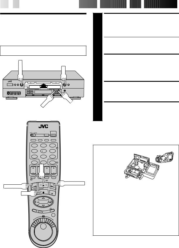
22

 EN
EN


 SIMPLE

 PLAYBACK

 AND
AND
 RECORDING

Simple
Playback
Turn on the TV and select the VCR channel 3 or 4 (or AV mode).
STOP/EJECT |
PLAY |
FF
REW
1
2
3
4
LOAD A CASSETTE
Make sure the window side is up, the rear label side is facing you and the arrow on the front of the cassette is pointing towards the VCR. Don’t apply too much pressure when inserting.
cThe VCR’s power comes on automatically.
cThe counter is automatically reset to "0:00:00".
cIf the cassette's record safety tab has been removed, playback begins automatically.
FIND PROGRAM START POINT
If the tape is advanced past the start point, press REW. To go forward, press FF.
START PLAYBACK
Press PLAY. "VIDEO CALIBRATION" appears on the screen (when VIDEO CALIBRATION is set to "ON" Z pg. 36).
STOP PLAYBACK
Press STOP or STOP/EJECT. Then press STOP/EJECT to remove the cassette.
1 |
2 |
3 |
|
|
2 |
4 |
5 |
6 |
7 |
8 |
9 |
|
0 |
4 |
|
PLAY |
|
1 |
|
|
REW (Rewind) |
|
FF (Fast-Forward) |
|
|
|
STOP |
|
|
|
|
3 |
Usable cassettes
Full-Size VHS
T-30 (ST-30**)
T-60 (ST-60**)
T-90
T-120 (ST-120**)
T-160 (ST-160**)
ST-210**
Compact VHS*
TC-20 (ST-C20**)
TC-30 (ST-C30**)
TC-40 (ST-C40**)
*Compact VHS camcorder recordings can be played on this video recorder. Simply place the recorded cassette into a VHS Cassette Adapter and it can be used just like any full-sized VHS cassette.
**This VCR can record on regular VHS and Super VHS cassettes. While only VHS signals can be recorded on regular VHS cassettes*, both VHS and Super VHS signals can be recorded and played back using Super VHS cassettes.
*By using S-VHS ET it is possible to record and play back with S-VHS picture quality on VHS cassettes with this VCR.
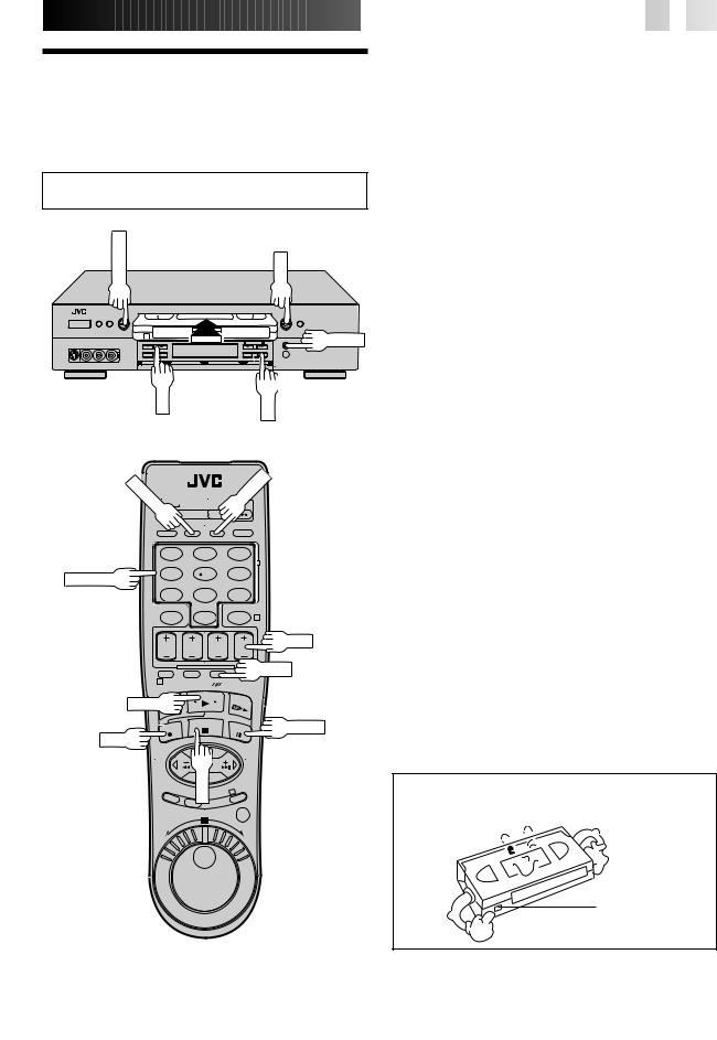
Simple
Recording
Turn on the TV and select the VCR channel 3 or 4 (or AV mode).
STOP/EJECT |
PLAY |
PAUSE
CH |
REC |
|
TV/VCR |
|
ENTER |
|
|
|
|
|
1 |
2 |
3 |
|
|
|
2 |
NUMBER |
4 |
5 |
6 |
|
|
|
|
|
7 |
8 |
9 |
|
|
0 |
4 |
CH
SP/EP
1
PLAY
PAUSE
REC
STOP |
3 |


 EN
EN
 23
23
|
1 |
|
LOAD A CASSETTE |
|
|
Make sure the record safety tab is intact. If not, cover the |
|
|
|
hole with adhesive tape before inserting the cassette. |
|
|
|
|
SELECT RECORDING |
|
2 |
|
CHANNEL |
|
|
Press CH5 (+/–). Or press the appropriate NUMBER |
|
|
|
keys, then press ENTER. (The channel changes after a |
|
|
|
few seconds whether you press ENTER or not.) |
|
|
|
|
c If you use the RF connection, by pressing the TV/VCR |
|
|
|
button, select VCR mode to view the program to be |
|
|
|
recorded. |
|
|
|
|
|
3 |
|
SET TAPE SPEED |
|
|
Press SP/EP to set the recording speed. |
|
|
4 |
|
START RECORDING |
|
|
Press and hold REC and press PLAY on the remote |
|
|
|
control, or press REC on the VCR's front panel. |
|
|
|
|
|
|
|
Video Calibration takes place at the beginning of |
|
|
|
|
both the first SP and the first EP recording after |
|
|
|
inserting the cassette (when Video Calibration is set |
|
|
|
to "ON", Z pg. 36). |
|
|
|
|
|
|
|
|
|
|
|
PAUSE/RESUME |
|
5 |
|
RECORDING |
|
|
Press PAUSE. Press PLAY to resume recording. |
|
|
|
|
|
|
|
c During record pause, you can change the recording |
|
|
|
channel by using the CH5(+/–) buttons or NUMBER |
|
|
|
|
keys. |
|
|
|
|
|
|
|
Video Calibration will not take place if the tape |
|
|
|
speed is changed while in record pause mode. |
|
|
|
|
|
|
|
|
|
6 |
|
STOP RECORDING |
|
|
Press STOP or STOP/EJECT. Then press STOP/EJECT to |
|
|
|
remove the cassette. |
|
|
|
|
|
Accidental erasure prevention
cTo prevent accidental recording on a recorded cassette, remove its record safety tab.
To record on it later, cover the hole with adhesive tape.
Record safety tab
 Loading...