


VIDEO CASSETTE RECORDER
HR-S3902/3912U 
INSTRUCTIONS
LPT0731-001B
CONTENTS |
|
Buttons, Connectors and Indicators ................................................ |
4 |
Connections and Plug&Play Setting ................................................ |
5 |
Initial Settings .............................................................................. |
6 |
Dear Customer,
Thank you for purchasing the JVC S-VHS video cassette recorder. Before use, please read the safety information and precautions to ensure safe use of your new VCR.
CAUTIONS
Language Setting .................................................................... |
6 |
Clock Setting .......................................................................... |
6 |
Tuner Setting .......................................................................... |
7 |
Cable Box and/or DBS Receiver Control Setting ..................... |
7 |
Playback ...................................................................................... |
9 |
Basic Playback ....................................................................... |
9 |
Playback Features ................................................................... |
9 |
Recording ................................................................................... |
11 |
Basic Recording ................................................................... |
11 |
Recording Features ............................................................... |
11 |
Timer Recording .......................................................................... |
12 |
Changing VCR Plus+® Setting ................................................ |
12 |
VCR Plus+® Timer Programing .............................................. |
12 |
Express Timer Programing .................................................... |
13 |
24HR Quick Programing ...................................................... |
13 |
Other Functions .......................................................................... |
14 |
Timer warning display .......................................................... |
14 |
Checking tape position ......................................................... |
14 |
Changing display information ............................................... |
14 |
Function settings .................................................................. |
14 |
Satellite Auto Recording ....................................................... |
16 |
Child Lock ............................................................................ |
16 |
Multi-Brand Remote Control ................................................ |
17 |
Changing Remote Control Code ........................................... |
17 |
Editing ....................................................................................... |
18 |
Editing with Another VCR...................................................... |
18 |
Specifications .............................................................................. |
19 |
Troubleshooting .......................................................................... |
20 |
FOR SERVICING (Only in U.S.A.) .................................................. |
21 |
WARRANTY (Only in U.S.A.) ....................................................... |
22 |
The lightning flash with arrowhead symbol, within an equilateral triangle, is intended to alert the user to the presence of uninsulated “dangerous voltage” within the product’s enclosure that may be of sufficient magnitude to constitute a risk of electric shock to persons.
The exclamation point within an equilateral triangle is intended to alert the user to the presence of important operating and maintenance (servicing) instructions in the literature accompanying the appliance.
WARNING:
TO PREVENT FIRE OR SHOCK HAZARD, DO NOT EXPOSE THIS UNIT TO RAIN OR MOISTURE.
CAUTION:
This video cassette recorder should be used with AC 120Vd, 60Hz only.
To prevent electric shocks and fire hazards, DO NOT use any other power source.
CAUTION:
TO PREVENT ELECTRIC SHOCK, MATCH WIDE BLADE OF PLUG TO WIDE SLOT, FULLY INSERT.
ATTENTION:
POUR ÉVITER LES CHOCS ÉLECTRIQUES, INTRODUIRE LA LAME LA PLUS LARGE DE LA FICHE DANS LA BORNE CORRESPONDANTE DE LA PRISE ET POUSSER JUSQU’AU FOND.
Note to CATV system installer:
This reminder is provided to call the CATV system installer’s attention to Article 820-40 of the NEC that provides guidelines for proper grounding and, in particular, specifies that the cable ground shall be connected to the grounding system of the building, as close to the point of cable entry as practical.
— 1 —

NOTE:
Change or modifications not approved by the party responsible for compliance could void the user’s authority to operate the equipment.
This equipment has been tested and found to comply with the limits for a Class B digital device, pursuant toPart 15 of the FCC Rules. These limits are designed to provide reasonable protection against harmful interference in a residential installation. This equipment generates, uses and can radiate radio frequency energy and, if not installed and used in accordance with the instructions, may cause harmful interference to radio communications. However, there is no guarantee that interference will not occur in a particular installation. If this equipment does cause harmful interference to radio or television reception, which can be determined by turning the equipment off and on, the user is encouraged to try to correct the interference by one or more of the following measures.
Reorient or relocate the receiving antenna. Increase the separation between the equipment and receiver.
Connect the equipment into an outlet on a circuit different from that to which the receiver is connected.
Consult the dealer or an experienced radio TV technician for help.
Declaration of Conformity
Model Number: |
HR-S3902/3912U |
Trade Name: |
JVC |
Responsible Party: |
JVC Americas Corp. |
Address: |
1700 Valley Road Wayne, N.J. 07470 |
Telephone Number: |
973-317-5000 |
This device complies with Part 15 of FCC Rules. Operation is subject to the following two conditions:
(1) This device may not cause harmful interference, and (2) this device must accept any interference received, including interference that may cause undesired operation.
Failure to heed the following precautions may result in damage to the VCR, Remote or video cassette.
1.DO NOT place the VCR . . .
...in an environment prone to extreme temperatures or humidity.
...in direct sunlight.
...in a dusty environment.
...in an environment where strong magnetic fields are generated.
...on a surface that is unstable or subject to vibration.
2.DO NOT block the VCR’s ventilation openings.
3.DO NOT place heavy objects on the VCR or on the Remote.
4.DO NOT place anything which might spill on the top of the VCR or on the Remote.
5.AVOID violent shocks to the VCR during transport.
VCR Plus+, C3 and PlusCode are registered trademarks of Gemstar Development Corporation.
The VCR Plus+ system is manufactured under license from Gemstar Development Corporation.
For Customer Use:
Enter below the Model No. and Serial No. which are located on the rear of cabinet. Retain this information for future reference.
Model No.
Serial No.
●Cassettes marked “S-VHS” and “VHS” can be used with this video cassette recorder. However, S-VHS recordings are possible only with cassettes marked “S-VHS”.
By using S-VHS ET it is possible to record and play back with S-VHS picture quality on VHS cassettes with this VCR.
●As an ENERGY STAR® Partner, JVC has determined that this product or product model meets the ENERGY STAR® guidelines for energy efficiency.
IMPORTANT PRODUCT SAFETY INSTRUCTIONS
Electrical energy can perform many useful functions. But improper use can result in potential electrical shock or fire hazards. This product has been engineered and manufactured to assure your personal safety. In order not to defeat the built-in safeguards, observe the following basic rules for its installation, use and servicing.
ATTENTION:
Follow and obey all warnings and instructions marked on your product and its operating instructions. For your safety, please read all the safety and operating instructions before you operate this product and keep this booklet for future reference.
INSTALLATION
1. Grounding or Polarization
(A)Your product may be equipped with a polarized alternatingcurrent line plug (a plug having one blade wider than the other). This plug will fit into the power outlet only one way. This is a safety feature.
If you are unable to insert the plug fully into the outlet, try reversing the plug. If the plug should still fail to fit, contact your electrician to replace your obsolete outlet. Do not defeat the safety purpose of the polarized plug.
(B)Your product may be equipped with a 3-wire grounding-type plug, a plug having a third (grounding) pin. This plug will only
fit into a grounding-type power outlet. This is a safety feature. If you are unable to insert the plug into the outlet, contact your electrician to replace your obsolete outlet. Do not defeat the safety purpose of the grounding-type plug.
2. Power Sources
Operate your product only from the type of power source indicated on the marking label. If you are not sure of the type of power supply to your home, consult your product dealer or local power company. If your product is intended to operate from battery power, or other sources, refer to the operating instructions.
3. Overloading
Do not overload wall outlets, extension cords, or integral convenience receptacles as this can result in a risk of fire or electric shock.
4. Power Cord Protection
Power supply cords should be routed so that they are not likely to be walked on or pinched by items placed upon or against them, paying particular attention to cords at plugs, convenience receptacles, and the point where they exit from the product.
5. Ventilation
Slots and openings in the cabinet are provided for ventilation.To ensure reliable operation of the product and to protect it from overheating, these openings must not be blocked or covered.
●Do not block the openings by placing the product on a bed, sofa, rug or other similar surface.
●Do not place the product in a built-in installation such as a
bookcase or rack unless proper ventilation is provided or the manufacturer’s instructions have been adhered to.
6. Wall or Ceiling Mounting
The product should be mounted to a wall or ceiling only as recommended by the manufacturer.
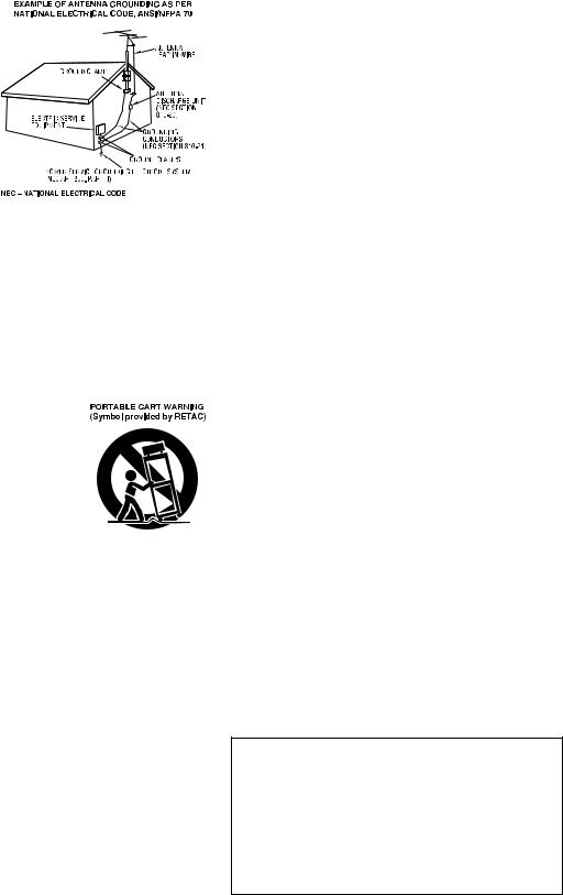
ANTENNA INSTALLATION INSTRUCTIONS
1. Outdoor Antenna Grounding
If an outside antenna or cable system is connected to the product, be sure the antenna or cable system is grounded so as to provide some protection against voltage surges and built-up static charges. Article 810 of the National Electrical Code, ANSI/NFPA 70, provides information with regard to proper grounding of the mast and supporting structure, grounding of the lead-in wire to an antenna discharge unit, size of grounding connectors, location of antenna discharge unit, connection to grounding electrodes, and requirements for the grounding electrode.
— 2 —
2. Lightning
For added protection for this product during a lightning storm, or when it is left unattended and unused for long periods of time, unplug it from the wall outlet and disconnect the antenna or cable system. This will prevent damage to the product due to lightning and power-line surges.
3. Power Lines
An outside antenna system should not be
located in the vicinity of overhead power lines or other electric light or
power circuits, or where
it can fall into such power lines or circuits. When installing an
outside antenna system, extreme care should be taken to keep from touching such power lines or circuits as
contact with them might be fatal.
USE
1. Accessories
To avoid personal injury:
●Do not place this product on an unstable cart, stand, tripod, bracket, or table. It may fall, causing serious injury to a child or adult, and serious damage to the product.
●Use only with a cart, stand, tripod, bracket, or table recommended by the manufacturer or sold with the product.
●Use a mounting accessory recommended by the manufacturer and follow the manufacturer’s instructions for any mounting of the product.
●Do not try to roll a cart with small casters across thresholds or deep-pile carpets.
2. Product and Cart Combination
A product and cart combination should be moved with care. Quick stops,
excessive force, and uneven surfaces may cause the product and cart combination
to overturn.
3. Water and Moisture
Do not use this product near water—for
example, near a bath tub, wash bowl, kitchen sink or laundry tub, in a wet
basement, or near a swimming pool and the like.
4. Object and Liquid Entry
Never push objects of any kind into this product through openings as they may touch dangerous voltage points or short-out parts that could result in a fire or electric shock. Never spill liquid of any kind on the product.
5. Attachments
Do not use attachments not recommended by the manufacturer of this product as they may cause hazards.
6. Cleaning
Unplug this product from the wall outlet before cleaning. Do not use liquid cleaners or aerosol cleaners. Use a damp cloth for cleaning.
7. Heat
The product should be situated away from heat sources such as radiators, heat registers, stoves, or other products (including amplifiers) that produce heat.
SERVICING
1. Servicing
If your product is not operating correctly or exhibits a marked change in performance and you are unable to restore normal operation by following the detailed procedure in its operating instructions, do not attempt to service it yourself as opening or removing covers may expose you to dangerous voltage or other hazards. Refer all servicing to qualified service personnel.
2. Damage Requiring Service
Unplug this product from the wall outlet and refer servicing to qualified service personnel under the following conditions:
a.When the power supply cord or plug is damaged.
b.If liquid has been spilled, or objects have fallen into the product.
c.If the product has been exposed to rain or water.
d.If the product does not operate normally by following the operating instructions. Adjust only those controls that are covered by the operating instructions as an improper adjustment of other controls may result in damage and will often require extensive work by a qualified technician to restore the product to its normal operation.
e.If the product has been dropped or damaged in anyway.
f.When the product exhibits a distinct change in performance— this indicates a need for service.
3. Replacement Parts
When replacement parts are required, be sure the service technician has used replacement parts specified by the manufacturer or which have the same characteristics as the original part. Unauthorized substitutions may result in fire, electric shock or other hazards.
4. Safety Check
Upon completion of any service or repairs to this product, ask the service technician to perform safety checks to determine that the product is in safe operating condition.
How to use the Remote
Before use, insert two AA size batteries into the Remote with the polarity ( and
and  ) matched correctly as indicated on the battery compartment or on the lid.
The Remote can operate most of your VCR’s functions, as well as basic functions of TV sets, cable boxes and DBS receivers.
●Point the Remote toward the remote sensor on the target component.
●The maximum operating distance of the Remote is about 8 m.
NOTE:
If the Remote does not work properly, remove its batteries, wait for a few seconds, replace the batteries and then try again.
Video heads cleaning
The heads get dirty in the following cases:
●in an environment prone to extreme temperature or humidity.
●in a dusty environment
●flaw, dirt or mold on video tapes
●continuous usage for a long time
Use a dry cleaning cassette — TCL-2 — when:
●Rough, poor picture appears while a tape is played back.
●The picture is unclear or no picture appears.
●“USE CLEANING CASSETTE” appears on the screen (only with “SUPERIMPOSE” set to “ON” ( pg. 15)).
ATTENTION:
To mobile phone users:
Using a mobile phone in the vicinity of the VCR may cause picture vibration on the TV screen or change the screen to a blue back display.
On placing the VCR:
Some TVs generate strong magnetic fields.
●Make sure to place the VCR at least 20 cm (7 or 8 inch) away from a TV.
●DO NOT place the VCR close to a TV as it may cause noise, picture disturbance or malfunctions (power off, etc.) to occur.
— 3 —

Buttons, Connectors and
Indicators
Remote
Front Panel
Number keys 
Cassette loading slot |
Advanced |
|
JOG dial |
|
|
|
REW |
FF |
|
|
|
24HR QUICK |
|
|
|
|
REC LINK PROGRAM |
|
|
|
POWER |
DISPLAY SP/EP |
|
S-VIDEO |
|
|
|
|
S-VIDEO |
VIDEO/AUDIO input |
Remote |
|
|
input |
connectors |
sensor |
|
|
connector |
|
|
|
|
Display panel |
Timer mode indicator |
|
||
|
|
|
||
Play indicator |
|
|
|
|
VCR mode |
|
|
|
|
indicator |
|
|
|
|
|
|
|
S-VHS |
Record indicator |
indicator |
|
Channel and auxiliary input/Clock time
Rear Panel
AC power cord
On-screen display
If you press OSD (OK) on the Remote when “SUPERIMPOSE” is set to “ON” ( pg. 15), you can see the current VCR status on the TV screen.
The indications are not recorded even if the VCR is in the recording mode.
|
|
|
|
|
|
Channel and |
Timer warning display |
VCR operation |
||||||||||||||||||||
|
|
|
|
|
|
auxiliary input |
mode |
|||||||||||||||||||||
|
|
|
|
|
|
|||||||||||||||||||||||
|
|
|
|
|
|
Day and |
|
|
|
|
|
|
|
|
|
|
|
|
|
|
|
|
|
|
|
|
|
|
|
|
|
|
|
|
clock time |
|
|
|
|
|
|
|
|
|
|
|
|
|
|
|
|
|
|
|
|
Tape speed |
|
|
|
|
|
|
|
STEREO |
|
|
|
|
|
|
|
|
|
|
|
|
|
|
|
|||||||
|
|
|
|
|
|
|
|
|
|
|
|
|
|
|
|
|
|
|||||||||||
|
|
|
|
|
|
|
|
|
|
|
|
|
|
|
|
|
|
|
|
|
|
|||||||
|
|
|
|
|
|
program |
|
|
|
|
|
|
|
|
|
|
|
|
|
|
|
Cassette mark |
||||||
|
|
|
|
|
|
indication |
|
|
|
|
|
|
|
|
|
|
|
|
|
|
|
|||||||
|
|
|
|
|
|
|
|
|
|
|
|
|
|
|
|
|
|
|
|
|
|
|||||||
|
|
|
|
|
|
SAP |
|
|
|
|
|
|
|
|
|
|
|
|
|
|
|
Tape position |
||||||
|
|
|
|
|
|
|
|
|
|
|
|
|
|
|
|
|
|
|
|
|
||||||||
|
|
|
|
|
|
indication |
|
|
|
|
|
|
|
|
|
|
|
|
|
|
|
Index number |
||||||
|
|
|
|
|
|
Audio |
|
|
|
|
|
|
|
|
|
|
|
|
|
|
|
|
|
|
|
|
|
|
|
|
|
|
|
|
|
|
|
|
|
|
|
|
|
|
|
|
|
|
|
|
|
|
|
|
|||
|
|
|
|
|
|
monitor |
|
|
|
|
|
|
|
|
|
|
|
|
|
|
|
|
|
|
Tape |
|||
|
|
|
|
|
|
|
|
|
|
|
|
|
|
|
|
|
|
|||||||||||
|
|
|
|
|
|
|
|
|
|
|
|
|
|
|
|
|
|
|
|
|
||||||||
|
|
|
|
|
|
indications |
|
|
|
|
|
|
|
|
|
|
|
|
|
|
|
remaining time |
||||||
Time counter
To recall an indication
APress OSD (OK).
●All indications corresponding to the current status are displayed for 5 seconds. After that, the counter information and RECORD/PAUSE (if in the Record Pause mode), remain on the TV screen.
BPress OSD (OK) again to clear the display.
● The RECORD/PAUSE indication remains on the TV screen.
— 4 —
Connections and Plug&Play
Setting
A Check contents
Make sure the package contains all of the accessories listed in “Specifications” ( pg. 19).
B Situate VCR
Place the VCR on a stable, horizontal surface.
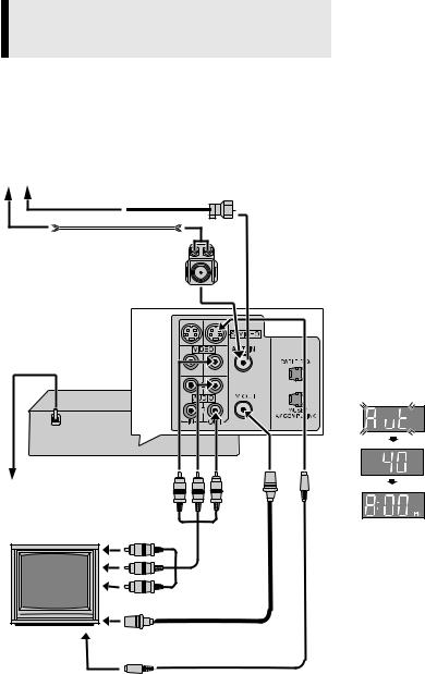
C Connect VCR to TV
Antenna or cable
Coaxial cable
Flat feeder |
Matching transformer (not supplied)
AC power cord |
Back of VCR |
AC outlet
To audio/video |
Audio/video |
|
input connectors |
||
|
cable |
|
|
(not supplied) |
|
To 75 terminal |
|
|
TV |
RF cable |
|
(supplied) |
||
|
||
To S-video input |
S-video cable |
|
connector |
(supplied) |
RF Connection
A Disconnect the TV antenna from the TV.
BConnect the TV antenna cable to the ANT. IN terminal on the rear of the VCR.
CConnect the supplied RF cable between the TV OUT terminal on the rear of the VCR and the TV’s antenna input terminal.
AV Connection
(improves picture quality during tape playback.)
If your TV is equipped with audio/video input connectors
A Connect the antenna, VCR and TV as shown in the illustration.
BConnect an audio/video cable between the AUDIO/VIDEO OUT connectors on the rear of the VCR and the audio/video input connectors on the TV.
S-video Connection
(allows you to make the most of the S-VHS picture performance.) If your TV is equipped with a S-video input connector
A Perform “RF Connection” previously described.
BConnect the supplied S-video cable between the S-VIDEO OUT connector on the rear of the VCR and the S-video input connector on the TV.
CConnect an audio cable between the AUDIO OUT connectors on the rear of the VCR and the audio input connectors on the TV.
●Even if you are using audio/video cables to connect your VCR to your TV, you must also connect it using the RF cable. This will ensure that you can record one show while watching another.
D Perform Plug&Play setup
Plug the AC power cord into an AC outlet. Do not turn on the VCR. The clock and tuner channels will be set automatically. The time and date can be set automatically by the clock setting data transmitted from one of the regular TV broadcast channels. We call this TV channel the “host channel” and it is a PBS channel in your area.
ATTENTION:
●If you use a cable box, Plug&Play will not function; set the clock and tuner channels separately ( pg. 6 – 7).
●Depending on areas or reception conditions, the VCR may not receive the Auto clock setting data from a PBS channel. If this function is taking a considerable amount of time, it may be
necessary to perform the procedure in “Semiauto Clock Set” ( pg. 6) or “Manual Clock Set” ( pg. 6).
During Initial Auto Clock Set
“Aut” blinks.
During Auto Channel Set
The channel numbers are displayed as they are scanned and set.
Plug&Play Completed
The current time is displayed.
What to do if Plug&Play setting failed
●If an incorrect time is displayed on the display panel, perform the procedure in “Semiauto Clock Set” ( pg. 6) or “Manual Clock Set” ( pg. 6).
●If “–:– –” appears on the display panel, ensure that the antenna cable is connected correctly. Then turn on and off the VCR; the Plug&Play setting will be automatically reactivated. If Plug&Play setting is not performed though the antenna cable is connected
correctly, perform the procedure in “Manual Clock Set” ( pg. 6) and “Auto Channel Set” ( pg. 7) or “Manual Channel Set” ( pg. 7).
E Set VCR channel
The VCR channel is the channel on which you can watch the picture from the VCR on the TV when only using the RF connection. Press POWER 1 to turn off the VCR, then press STOP/EJECT (0) on the VCR for more than 5 seconds. “CH3” appears on the display panel. Press CH+/– on the Remote to select “CH3”, “CH4” or “CH–”(OFF), then press OK.
●The VCR channel is preset to “CH3”. Set to “CH4” if CH3 is used for broadcasting in your area.
F Final preparation for use
Turn on the VCR and the TV, and select the VCR channel 3 or 4 (or AV mode) on the TV. You can now perform basic playback or basic recording.
●If you connect the TV and the VCR only using the RF connection, press TV/VCR on the Remote so that the VCR mode indicator lights on the display panel.
— 5 —
 Initial Settings
Language Setting
The default setting is “ENGLISH”.
Turn on the VCR and TV, and select the VCR channel (or AV mode).
A Access Main Menu screen, then Initial |
MAIN MENU |
||
Set screen |
TUNER SET |
||
|
|
FUNCTION SET |
|
Press MENU on the Remote. Press rtto |
INITIAL SET |
|
|
|
|
||
move the highlight bar (arrow) to “INITIAL |
|
|
|
SET”, then press OK or e. |
|
|
|
|
PRESS ( , ), THEN (OK) |
||
|
|
PRESS (MENU) TO END |
|
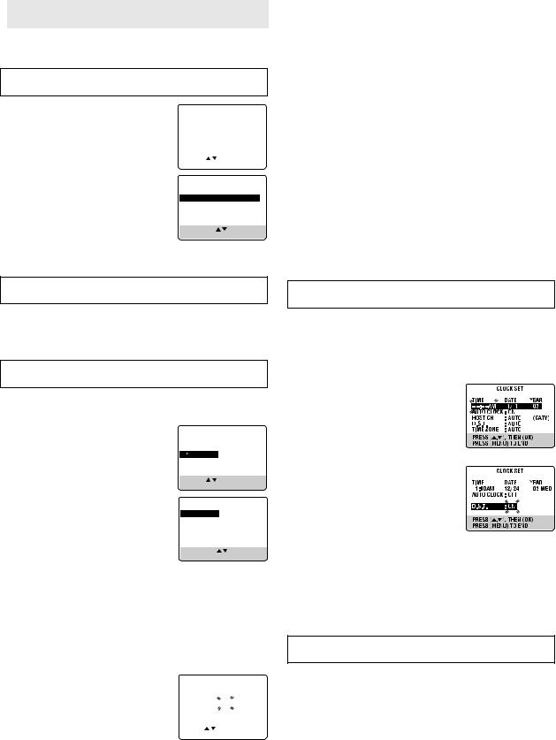
B Select language
This VCR offers you the language choice to view menus and some messages — in English, Spanish or French. Press rtto move the highlight bar (arrow) to “LANGUAGE”, then press OK or e repeatedly until the desired language is selected.
Press MENU to return to normal screen.
INITIAL SET
CLOCK SET
 LANGUAGE ENGLISH GUIDE CHANNEL SET CABLE BOX SET
DBS RECEIVER SET
SELECT WITH ( , ) AND (OK) PRESS (MENU) TO END
Language selection will be reset to “ENGLISH” after a power failure occurs.
C Select D.S.T. mode
Press OK or eto move the highlight bar to “D.S.T.”, then press rtrepeatedly until the desired setting is selected.
AUTO: Select if you want to adjust your VCR’s clock automatically by the incoming signal from the host channel. (Auto Daylight Saving Time enables automatic adjustment of the VCR’s clock at the start and end of Daylight Saving Time.) Be sure to select the correct time zone manually in step 4.
ON: Adjustment will be made by the built-in clock itself.
OFF: Select when Daylight Saving Time does not apply to you.
D Select time zone
Press OK or eto move the highlight bar to “TIME ZONE”, then press rtrepeatedly until “AUTO” or the desired time zone is selected. Each time you press the button, the time zone changes as follows:
{AUTO {ATLANTIC {EASTERN {CENTRAL
{MOUNTAIN {PACIFIC {ALASKA {HAWAII
{(back to the beginning)
E Complete Semiauto Clock Set
Press MENU to return to normal screen.Turn off the VCR. “Aut” will appear on the display panel while the clock is being set. The current clock time will appear automatically when the clock setting is complete.
Selections of host channel and D.S.T. mode will be reset to “AUTO” after a power failure occurs.
Clock Setting
Perform clock setting only if the clock has not been set correctly by the Plug&Play setting or if you use a cable box.
Turn on the VCR and TV, and select the VCR channel (or AV mode).
Preparations
A Access Main Menu screen, then Initial
Set screen
Press MENU on the Remote. Press rtto move the highlight bar (arrow) to “INITIAL SET”, then press OK or e.
MAIN MENU
FUNCTION SET
TUNER SET
INITIAL SET
PRESS ( , ), THEN (OK) PRESS (MENU) TO END
B Access Clock Set screen
Press rtto move the highlight bar (arrow) to “CLOCK SET”, then press OK or e.
Setting clock semiautomatically
— Semiauto Clock Set
INITIAL SET
 CLOCK SET
LANGUAGE ENGLISH GUIDE CHANNEL SET CABLE BOX SET
DBS RECEIVER SET
SELECT WITH ( , ) AND (OK) PRESS (MENU) TO END
Setting clock manually
— Manual Clock Set
First follow steps 1 to 2 in “Preparations” above, then go to the following steps.
A Set time, date and year
Press rtuntil the desired time appears, then press OK or e. Set the date and year
in the same way. ● Holding rtchanges the time in 30-
minute intervals, or changes the date in 15-day intervals.
B Select D.S.T. mode
Press OK or eto move the highlight bar to “D.S.T.”, then press rtto select the desired setting.
ON: Adjustment will be made by the
built-in clock itself. OFF: Select when Daylight Saving Time
does not apply to you.
C Start clock
Press MENU and normal screen appears.
You can change the host channel/D.S.T. (Daylight Saving Time)/ time zone setting manually. First follow steps 1 to 2 in “Preparations” above, then go to the following steps.
NOTE:
The time set previously will be erased when “AUTO CLOCK”, “HOST CH”, “D.S.T.” or “TIME ZONE” setting is changed.
A Set Auto Clock to ON |
|
CLOCK SET |
|
||
Press OK or eon the Remote repeatedly to |
|
TIME |
DATE |
YEAR |
|
move the highlight bar to “AUTO CLOCK”, |
|
– –:– – AM |
1/ 1 |
|
03 |
|
AUTO CLOCK : ON |
|
(CATV) |
||
then press rtso that “ON” is selected. |
|
HOST CH |
: AUTO |
||
|
D.S.T. |
: AUTO |
|
||
|
|
TIME ZONE |
: AUTO |
|
|
|
|
PRESS ( , |
), THEN (OK) |
||
B Select host channel |
|
PRESS (MENU) TO END |
|
||
|
|
|
|
|
|
To make corrections any time during the process
Press OK or erepeatedly until the item you want to change blinks, then press rt.
Manual setting of the clock will be lost after a power failure occurs.
You can either select “AUTO” or enter a PBS channel number. Press OK or eto move the highlight bar to “HOST CH”, then press rtrepeatedly until “AUTO” or the desired PBS channel number is selected.
● Some PBS channels do not transmit clock setting data.
CONTINUED ON NEXT PAGE
— 6 —
Tuner Setting
Turn on the VCR and TV, and select the VCR channel (or AV mode).
Setting channels automatically
— Auto Channel Set
Perform Auto Channel Set only if channels have not been set correctly by the Plug&Play setting.
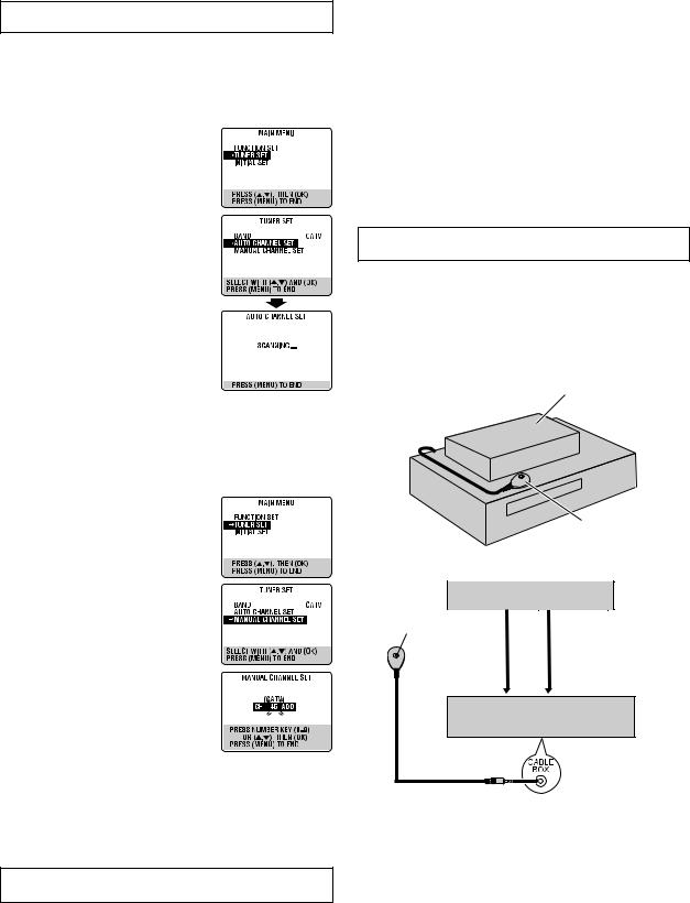
A Access Main Menu screen, then Tuner
Set screen
Press MENU on the Remote. Press rtto move the highlight bar (arrow) to “TUNER SET”, then press OK or e.
B Perform Auto Channel Set
Press rtto move the highlight bar (arrow) to “AUTO CHANNEL SET”, then press OK or e. The VCR selects the correct band (TV or CATV) automatically during Auto Channel Set.
● When Auto Channel Set is complete, “SCAN COMPLETED” appears on screen.
●If the scan was unsuccessful, “SCAN COMPLETED–NO SIGNAL–” appears on
screen. Check the connections and start again.
Press MENU to return to normal screen.
Setting channels manually
— Manual Channel Set
You can add the channels you want or delete the channels you do not want manually.
A Access Main Menu screen, then Tuner
Set screen
Press MENU on the Remote. Press rtto move the highlight bar (arrow) to “TUNER SET”, then press OK or e.
B Access Manual Channel Set screen
Press rtto move the highlight bar (arrow) to “MANUAL CHANNEL SET”, then press OK or e.
C Add or skip desired channels
To add channels
A Press the Number keys on the Remote to input a channel number you want to add.
B Press OK or eto set to “ADD”.
C Repeat A to B to add other channels. Press MENU to return to normal screen.
To skip channels
APress rtor the Number keys to select a channel number you want to skip.
B Press OK or eto set to “SKIP”.
CRepeat A and B to skip other channels. Press MENU to return to normal screen.
After a power failure occurs, band selection will be reset to “CATV”.
Cable Box and/or DBS Receiver Control Setting
The following procedure is required if you receive your TV channels through a cable box (descrambler) and/or if you receive satellite channels through DBS (Direct Broadcast Satellite) receiver. The Controller allows the VCR to automatically switch the cable box or DBS receiver’s channel during timer recording.
NOTES:
●The Controller is not supplied with this unit. It can be requested by mailing in the completed JVC Cable Mouse Certificate that is included with the accessory package.
●For the cable box, the Controller is effective for VCR Plus+ or Express timer programing.
●For the DBS receiver, the Controller is effective only for Express timer programing.
●When connecting your cable box or DBS receiver, refer to its instruction manual.
Turn on the VCR and TV, and select the VCR channel (or AV mode).
A Situate Controller
If both a cable box and a DBS receiver are used, position the Controller so its signal reaches the remote sensors on both the cable box and DBS receiver.
B Attach Controller
Fix securely using the adhesive strip attached on the back of the Controller.
Cable box or DBS receiver
Your VCR |
|
Controller |
|
(suggested locations) |
|
C Connect cable box and/or DBS receiver to VCR |
||
|
Cable box or DBS receiver |
|
Transmitter |
RF out |
Audio/video output |
|
|
|
Controller |
|
|
|
To ANT. IN |
To AUDIO/VIDEO IN |
|
|
VCR |
●If your cable box or DBS receiver does not have audio/video output connectors, connect the RF output terminal on the unit to the ANT. IN terminal on the rear of your VCR.
●If your cable box or DBS receiver has audio/video output connectors, connect an audio/video cable between the AUDIO/ VIDEO IN connectors on the rear of the VCR and the audio/ video output connectors on the unit.
●If both a cable box and a DBS receiver are used, it is recommended that you connect the DBS receiver to your VCR’s AUDIO/VIDEO IN connectors and the cable box to your VCR’s ANT. IN connector.
CONTINUED ON NEXT PAGE
— 7 —
D Connect Controller to VCR
Connect the Controller to the CABLE BOX Controller connector on the rear panel.
E Turn on cable box or DBS receiver
Select a channel other than channel 9 on your cable box, or channels 100, 205 on your DBS receiver.
F Access Main Menu screen, then Initial Set screen on VCR
Press MENU on the Remote. Press rtto move the highlight bar (arrow) to “INITIAL SET”, then press OK or e.
G Access Cable Box Set screen or DBS
Receiver Set screen
Press rtto move the highlight bar (arrow) to “CABLE BOX SET” or “DBS RECEIVER SET”, then press OK or e.
H Select output channel
Your selection depends on how the unit is connected to your VCR.
●If the unit is connected to your VCR’s ANT. IN terminal on the rear panel,
Press rtuntil the channel number representing the cable box’s output (CH2
– CH9) or DBS receiver’s output (CH3 or CH4) appears on the screen.
●If the unit is connected to your VCR’s AUDIO/VIDEO IN connectors on the front panel, press rtuntil “ON F-1 (FRONT)” appears on the screen.
●If the unit is connected to your VCR’s AUDIO/VIDEO IN connectors on the rear panel, press rtuntil “ON L-1 (REAR)” appears on the screen.
●If you do not use any unit, press rtuntil “OFF” appears on the screen.
I Access Brand Set screen
Press OK or e.
●If the Clock Set screen appears, perform “Manual Clock Set”. If you press MENU after the clock has been set, the Brand Set screen appears.
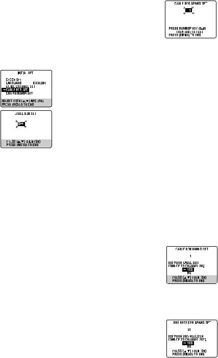
J Enter brand code and perform test
Press the appropriate Number keys on the Remote to enter the brand code from the following list, then press OK or e.
|
|
|
|
|
|
|
|
CABLE BOX BRAND |
CODE |
||
|
|
|
|
ARCHER |
1, 5, 17 |
|
|
CABLETENNA |
1, 17 |
|
|
CABLEVIEW |
15, 16, 17, 21, 25 |
|
|
CITIZEN |
15, 16, 17, 21, 25 |
|
|
CURTIS |
2, 8 |
|
|
DIAMOND |
1, 17 |
|
|
GC BRAND |
15, 16, 17, 21, 25 |
|
|
GEMINI |
15 |
|
|
GENERAL INSTRUMENTS |
1, 4, 6, 11, 12, 15, 28 |
|
|
HAMLIN |
10, 18, 23 |
|
|
JASCO |
15 |
|
|
JERROLD |
1, 4, 6, 11, 12, 15, 28 |
|
|
NOVAVISION |
2, 8 |
|
|
OAK |
7, 20 |
|
|
PANASONIC |
13, 14 |
|
|
PULSER |
15, 16, 17, 21, 25 |
|
|
RCA |
13, 14 |
|
|
REGAL |
10, 18, 23 |
|
|
REMBRANDT |
1, 16, 17 |
|
|
SAMSUNG |
5, 16, 24 |
|
|
SCIENTIFIC ATLANTA |
2, 8 |
|
|
SIGMA |
7, 20 |
|
|
SL MARX |
5, 16, 17, 24, 25 |
|
|
SPRUCER |
13, 14 |
|
|
STARGATE |
5, 15, 16, 17, 21, 24, 25 |
|
|
TELEVIEW |
5, 16, 24 |
|
|
TOCOM |
1, 4, 16 |
|
|
UNIKA |
1, 17 |
|
|
UNIVERSAL |
16, 17, 25 |
|
|
VIDEOWAY |
3, 9, 22 |
|
|
ZENITH |
3, 9, 22 |
|
|
|
|
|
|
DBS RECEIVER BRAND |
CODE |
DBS RECEIVER BRAND |
CODE |
|
|
|
|
JVC (DISH Network) |
51 |
SONY (DSS) |
41 |
ECHOSTAR (DISH |
51 |
RCA (DSS) |
40 |
Network) |
|
|
|
For cable box
●If the cable box’s channel changes to 9, setting is complete. Press OK.
● If the cable box’s channel does not change to 9;
A Press rtto move the highlight bar (arrow) to “NO”, then press OK or e.
BRepeat step 0 until the cable box’s channel changes to 9 by entering another code.
CIf the channel does not change after going through all the code numbers listed for your model of cable box, then try all the
other numbers.
For DBS receiver
● If the DBS receiver’s channel changes to the channel listed below for your brand, setting is complete. Press OK or e.
JVC |
] 205 |
SONY ]205 |
|
ECHOSTAR ] 205 |
RCA ]205 |
|
|
●If the DBS receiver’s channel does not change as shown above;
APress rtto move the highlight bar (arrow) to “NO”, then press OK or e.
B Repeat step 0.
— 8 —
 Loading...