


SERVICE MANUAL
DVD/CD PLAYER Hi-Fi STEREO VIDEO CASSETTE RECORDER
HR-XVC20US,
HR-XVC21UC
SPECIFICATIONS (The specifications shown pertain specifically to the model HR-XVC20US.)
GENERAL |
|
|
DVD section |
|
|
Power supply: |
AC 120V 60Hz |
Signal system: |
NTSC |
|
|
Power consumption: |
Operation: 16W |
Applicable disc: |
DVD (12cm, 8cm), CD (12cm, 8cm) |
||
|
Stand by: 2W |
Audio characteristics: |
DVD: 4Hz - 22KHz |
||
Weight: |
7.9lbs (3.6 kg) |
Frequency response: |
CD: 4Hz - 20KHz |
||
Dimensions: |
Width : 16-15/16 inches (430 mm) |
S/N Ratio: |
90dB |
|
|
|
Height: |
3-7/8 inches (99 mm) |
Harmonic distortion: |
0.02% |
|
|
Depth : |
9-13/16 inches (249 mm) |
Wow and flutter: |
Below Measurable Level |
|
Inputs/Outputs: |
|
|
Dynamic range: |
90dB |
|
Video: |
In: 1Vp-p/75 ohm |
Output: |
Video : |
(RCA) 1 Vp-p/75ohm |
|
|
Out: 1Vp-p/75 ohm |
|
Audio : |
(RCA) -8 dBm/1Kohm |
|
Audio: |
In: -8 dBm/50K ohm |
|
Digital Audio : 0.5Vp-p 75 ohm |
||
|
Out: -8 dBm/1K ohm |
Pickup: |
CD : |
Wavelength: 775 - 805 nm |
|
Antenna: |
UHF/VHF IN/OUT: 75 ohm coaxial |
|
|
Maximum output power: 0.5 mW |
|
Hi-Fi Frequency Response: 20Hz to 20,000Hz |
|
DVD : Wavelength: 640 - 660 nm |
|||
Hi-Fi Dynamic Range: |
More than 90dB |
|
|
Maximum output power: 1.0 mW |
|
VCR section |
|
|
ACCESSORIES: |
Remote control x 1 |
|
Video Head: |
4 Rotary Heads |
|
Batteries (2 x AA) |
||
Audio Track: |
Hi-Fi Sound - 2 Tracks / MONO Sound - 1 Track |
|
75 ohm Coaxial Cable x 1 |
||
Tuner: |
181 Channel Freq. Synthesized |
|
AUDIO/VIDEO Cable x 1 |
||
|
VHF |
2-13 |
|
|
|
|
UHF |
14-69 |
|
|
|
|
CATV |
14-36 (A)-(W) |
|
|
|
|
|
37-59 (AA)-(WW) |
|
|
|
|
|
60-85 (AAA)-(ZZZ) |
|
|
|
|
|
86-94 (86)-(94) |
|
|
|
|
|
95-99 (A-5)-(A-1) |
|
|
|
|
|
100-125 (100)-(125) |
|
|
|
|
|
01 (5A) |
|
|
|
RF Channel Output: |
Channel 3 or 4, Switchable |
|
|
|
|
F.FWD/REW Time: |
Approx. 1 minute 48 seconds (with T-120 Cassette Tape) (at+25°C) |
HR-XVC20US, HR-XVC21UC D2VP11 |
|||
|
|
|
|
||
|
|
This service manual is printed on 100% recycled paper. |
|
No.82948 |
|
|
|
COPYRIGHT © 2002 VICTOR COMPANY OF JAPAN, LTD |
|
2002/12 |
|
|
|
|
|
|
|
TABLE OF CONTENTS
Section |
Title |
Page |
Important Safety Precautions |
|
|
INSTRUCTIONS |
|
|
DISASSEMBLY INSTRUCTIONS |
|
|
1. REMOVAL OF MECHANICAL PARTS AND P.C.BOARDS ............... |
1-1 |
|
1-1 TOP CABINET AND FRONT CABINET ............................ |
1-1 |
|
1-2 FLAP .................................................................................. |
|
1-1 |
1-3 DECK CD ........................................................................... |
|
1-1 |
1-4 VCR DECK ........................................................................ |
|
1-2 |
1-5 VCR/DVD PCB .................................................................. |
|
1-2 |
2. REMOVAL OF VCR DECK PARTS ......................................... |
1-3 |
|
2-1 TOP BRACKET .................................................................. |
|
1-3 |
2-2 CASSETTE HOLDER ASS’Y ............................................. |
1-3 |
|
2-3 CASSETTE SIDE L/R ........................................................ |
|
1-3 |
2-4 LINK UNIT ......................................................................... |
|
1-3 |
2-5 LINK LEVER / FLAP LEVER ............................................. |
1-3 |
|
2-6 LOADING MOTOR / WORM .............................................. |
1-4 |
|
2-7 TENSION ASS’Y ................................................................ |
|
1-4 |
2-8 T BRAKE ARM / T BRAKE BAND ...................................... |
1-5 |
|
2-9 S REEL / T REEL / IDLER ARM ASS’Y / IDLER GEAR .............. |
1-5 |
|
2-10 CASSETTE OPENER / PINCH ROLLER BLOCK / P5ARM ASS’Y ............. |
1-6 |
|
2-11 A/C HEAD ........................................................................ |
|
1-6 |
2-12 FE HEAD ......................................................................... |
|
1-6 |
2-13 CYLINDER UNIT ASS’Y .................................................. |
1-6 |
|
2-14 CAPSTAN DD UNIT ......................................................... |
|
1-7 |
2-15 MAIN CAM / PINCH ROLLER CAM / JOINT GEAR ............ |
1-7 |
|
2-16 LOADING GEAR S/T UNIT .............................................. |
1-7 |
|
2-17 CLUTCH ASS’Y / RING SPRING / CLUTCH LEVER / CLUTCH GEAR ............... |
1-8 |
|
2-18 CASSETTE GUIDE POST / INCLINED BASE S/T UNIT / P4 CAP.............. |
1-8 |
|
3. REMOVAL AND INSTALLATION OF FLAT PACKAGE IC ........... |
1-9 |
|
REMOVAL ................................................................................ |
|
1-9 |
INSTALLATION ...................................................................... |
|
1-10 |
KEY TO ABBREVIATIONS ...................................................... |
|
1-11 |
SERVICE MODE LIST .............................................................. |
|
1-13 |
WHEN “N” IS ALWAYS BEING DISPLAYED ON THE TV MONITOR . 1-13 |
||
PARENTAL CONTROL - RATING LEVEL 4-DIGIT PASSWORD CANNCELLATION . 1-13 |
||
WHEN REPLACING EEPROM(MEMORY) IC ......................... |
1-14 |
|
PREVENTIVE CHECKS AND SERVICE INTERVALS ............. |
1-15 |
|
CONFIRMATION OF HOURS USED ....................................... |
1-15 |
|
CLEANING ............................................................................... |
|
1-15 |
SERVICING FIXTURES AND TOOLS ...................................... |
1-16 |
|
MECHANISM ADJUSTMENT PARTS LOCATION GUIDE ............ |
1-16 |
|
MECHANICAL ADJUSTMENT ................................................ |
1-17 |
|
TAPE REMOVAL METHOD AT NO POWER SUPPLY .......... |
1-17 |
|
DISC REMOVAL METHOD AT NO POWER SUPPLY ........... |
1-17 |
|
1. CONFIRMATION AND ADJUSTMENT ................................. |
1-17 |
|
1-1 CONFIRMATION AND ADJUSTMENT OF TENSION POST POSITION . 1-17 |
||
1-2 CONFIRMATION OF PLAYBACK TORQUE AND |
|
|
BACK TENSION TORQUE DURING PLAYBACK ........... |
1-17 |
|
1-3 CONFIRMATION OF VSR TORQUE ............................... |
1-17 |
|
1-4 CONFIRMATION OF REEL BRAKE TORQUE ................ |
1-18 |
|
2. CONFIRMATION AND ADJUSTMENT OF TAPE |
|
|
RUNNING MECHANISM .................................................. |
1-18 |
|
2-1 GUIDE ROLLER .............................................................. |
|
1-18 |
2-2 CONFIRMATION AND ADJUSTMENT OF AUDIO/CONTROL HEAD . 1-19 2-3 TAPE RUNNING ADJUSTMENT(X-VALUE ADJUSTMENT) . 1-19
ELECTRICAL ADJUSTMENTS ............................................... |
1-20 |
1. BASIC ADJUSMENT ............................................................ |
1-20 |
1-1 SWITCHING POINT ........................................................ |
1-20 |
ELECTRICAL ADJUSTMENT PARTS LOCATION GUIDE ............ |
1-20 |
IC DESCRIPTIONS .................................................................. |
1-21 |
SERVO TIMING CHART .......................................................... |
1-24 |
MECHANISM TIMING CHART ................................................. |
1-25 |
TROUBLE SHOOTING GUIDE ................................................ |
1-26 |
(VCR SECTION) .................................................................... |
1-26 |
(DVD SECTION) .................................................................... |
1-49 |
Section |
Title |
Page |
CHARTS AND DIAGRAMS |
|
|
INTERCONNECTION DIAGRAM ............................................ |
2-1 |
|
Y/C/AUDIO/CCD/HEAD AMP SCHEMATIC DIAGRAM .......... |
2-3 |
|
VCR SYSCON SCHEMTAIC DIAGRAM ................................. |
2-5 |
|
TUNER/JACK SCHEMATIC DIAGRAM .................................. |
2-7 |
|
OPERATION/DISPLAY SCHEMATIC DIAGRAM .................... |
2-9 |
|
HI-FI/DEMODULATOR SCHEMATIC DIAGRAM .................. |
2-11 |
|
POWER SCHEMATIC DIAGRAM ......................................... |
2-13 |
|
MPEG/MICOM SCHEMATIC DIAGRAM ............................... |
2-15 |
|
MEMORY SCHEMATIC DIAGRAM ....................................... |
2-17 |
|
DSP SCHEMATIC DIAGRAM |
................................................ |
2-19 |
MOTOR DRV SCHEMATIC DIAGRAM ................................. |
2-21 |
|
READ CHANNEL SCHEMATIC ...........................DIAGRAM |
2-23 |
|
AUDIO/VIDEO SCHEMATIC DIARAM .................................. |
2-25 |
|
OPERATION SCHEMATIC DIAGRAM .................................. |
2-27 |
|
PRINTED CIRCUIT BOARD OPERATION ............................ |
2-29 |
|
PRINTED CIRCUIT BOARD VCR/DVD ................................. |
2-31 |
|
WAVEFORMS ....................................................................... |
|
2-35 |
DVD BLOCK DIAGRAM ........................................................ |
|
2-37 |
Y/C/AUDIO/CCD/HEAD AMP .................BLOCK DIAGRAM |
2-39 |
|
SYSTEM CONTROL BLOCK ...............................DIAGRAM |
2-41 |
|
HI-FI/DEMODULATOR BLOCK ...........................DIAGRAM |
2-43 |
|
TUNER/JACK BLOCK DIAGRAM ......................................... |
2-45 |
|
POWER BLOCK DIAGRAM .................................................. |
|
2-47 |
PARTS LIST |
|
|
3.1 PACKING AND ACCESSORY ................ASSEMBLY<M1> |
3-1 |
|
3.2 FINAL ASSEMBLY<M2> ...................................................... |
|
3-2 |
3.3 MECHANISM ASSEMBLY<M4> .......................................... |
3-4 |
|
3.4 ELECTRICAL PARTS LIST .................................................. |
|
3-7 |
VCR/DVD BOARD ASSEMBLY<03> ....................................... |
3-7 |
|
OPERATION BOARD ASSEMBLY<28> ................................. |
3-15 |
|
REFERENCE |
|
|
SEMICONDUCTOR BASE CONNECTIONS .......................... |
4-1 |
|
GENERAL SPECIFICATIONS[HR ........................-XVC20US] |
4-2 |
|
Important Safety Precautions
Prior to shipment from the factory, JVC products are strictly inspected to conform with the recognized product safety and electrical codes of the countries in which they are to be sold. However, in order to maintain such compliance, it is equally important to implement the following precautions when a set is being serviced.
v Precautions during Servicing
1.Locations requiring special caution are denoted by labels and inscriptions on the cabinet, chassis and certain parts of the product. When performing service, be sure to read and comply with these and other cautionary notices appearing in the operation and service manuals.
2.Parts identified by the  symbol and shaded (
 ) parts are critical for safety.
Replace only with specified part numbers.
Note: Parts in this category also include those specified to comply with X-ray emission standards for products using cathode ray tubes and those specified for compliance with various regulations regarding spurious radiation emission.
3.Fuse replacement caution notice.
Caution for continued protection against fire hazard. Replace only with same type and rated fuse(s) as specified.
4.Use specified internal wiring. Note especially:
1)Wires covered with PVC tubing
2)Double insulated wires
3)High voltage leads
5.Use specified insulating materials for hazardous live parts.
Note especially: |
|
|
|
|
1) |
Insulation Tape |
3) |
Spacers |
5) Barrier |
2) |
PVC tubing |
4) |
Insulation sheets for transistors |
|
6.When replacing AC primary side components (transformers, power cords, noise blocking capacitors, etc.) wrap ends of wires securely about the terminals before soldering.
Fig.1
7.Observe that wires do not contact heat producing parts (heatsinks, oxide metal film resistors, fusible resistors, etc.)
8.Check that replaced wires do not contact sharp edged or pointed parts.
9.When a power cord has been replaced, check that 10-15 kg of force in any direction will not loosen it.
Power cord
Fig.2
10.Also check areas surrounding repaired locations.
11.Products using cathode ray tubes (CRTs)
In regard to such products, the cathode ray tubes themselves, the high voltage circuits, and related circuits are specified for compliance with recognized codes pertaining to X-ray emission.
Consequently, when servicing these products, replace the cathode ray tubes and other parts with only the specified parts.
Under no circumstances attempt to modify these circuits. Unauthorized modification can increase the high voltage value and cause X-ray emission from the cathode ray tube.
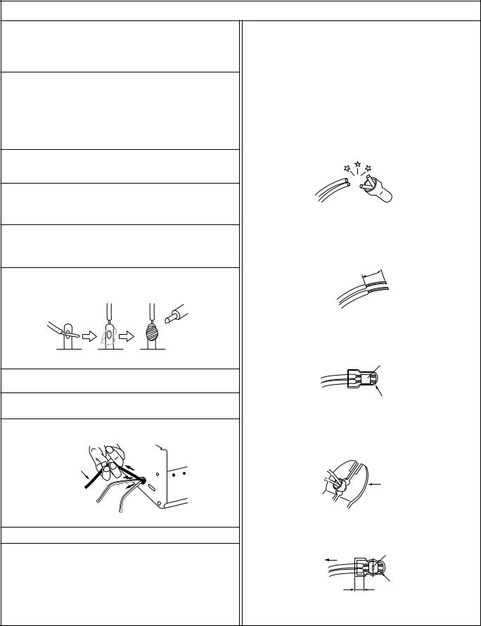
12.Crimp type wire connector
In such cases as when replacing the power transformer in sets where the connections between the power cord and power transformer primary lead wires are performed using crimp type connectors, if replacing the connectors is unavoidable, in order to prevent safety hazards, perform carefully and precisely according to the following steps.
1)Connector part number : E03830-001
2)Required tool : Connector crimping tool of the proper type which will not damage insulated parts.
3)Replacement procedure
(1)Remove the old connector by cutting the wires at a point close to the connector.
Important : Do not reuse a connector (discard it).
cut close to connector
Fig.3
(2)Strip about 15 mm of the insulation from the ends of the wires. If the wires are stranded, twist the strands to avoid frayed conductors.
15 mm
Fig.4
(3)Align the lengths of the wires to be connected. Insert the wires fully into the connector.
Metal sleeve
Connector
Fig.5
(4)As shown in Fig.6, use the crimping tool to crimp the metal sleeve at the center position. Be sure to crimp fully to the complete closure of the tool.
25 |
Crimping tool |
1. |
|
2. |
|
0 |
|
5. |
|
5 |
|
Fig.6
(5) Check the four points noted in Fig.7.
Not easily pulled free |
Crimped at approx. center |
|
|
of metal sleeve |
|
|
|
|
|
|
Conductors extended |
Wire insulation recessed |
|
|
more than 4 mm |
|
|
Fig.7 |
|
|
1 |
S40888-01 |

v Safety Check after Servicing
Examine the area surrounding the repaired location for damage or deterioration. Observe that screws, parts and wires have been returned to original positions, Afterwards, perform the following tests and confirm the specified values in order to verify compliance with safety standards.
1.Insulation resistance test
Confirm the specified insulation resistance or greater between power cord plug prongs and externally exposed parts of the set (RF terminals, antenna terminals, video and audio input and output terminals, microphone jacks, earphone jacks, etc.). See table 1 below.
2.Dielectric strength test
Confirm specified dielectric strength or greater between power cord plug prongs and exposed accessible parts of the set (RF terminals, antenna terminals, video and audio input and output terminals, microphone jacks, earphone jacks, etc.). See table 1 below.
3.Clearance distance
When replacing primary circuit components, confirm specified clearance distance (d), (d’) between soldered terminals, and between terminals and surrounding metallic parts. See table 1 below.
Chassis
Fig. 8
d |
d' |
Power cord, |
primary wire |
4.Leakage current test
Confirm specified or lower leakage current between earth ground/power cord plug prongs and externally exposed accessible parts (RF terminals, antenna terminals, video and audio input and output terminals, microphone jacks, earphone jacks, etc.).
Measuring Method : (Power ON)
Insert load Z between earth ground/power cord plug prongs and externally exposed accessible parts. Use an AC voltmeter to measure across both terminals of load Z. See figure 9 and following table 2.
|
a |
b |
Externally |
Z |
c |
|
|
|
exposed |
V |
|
accessible part |
|
|
|
Fig. 9 |
|
5.Grounding (Class 1 model only)
Confirm specified or lower grounding impedance between earth pin in AC inlet and externally exposed accessible parts (Video in, Video out, Audio in, Audio out or Fixing screw etc.).
Measuring Method:
Connect milli ohm meter between earth pin in AC inlet and exposed accessible parts. See figure 10 and grounding specifications.
AC inlet |
Grounding Specifications |
|
Exposed accessible part |
Grounding Impedance (Z) |
|
|
Region |
|
|
USA & Canada |
Z ≤ 0.1 ohm |
Earth pin |
Europe & Australia |
Z ≤ 0.5 ohm |
Milli ohm meter
Fig. 10
AC Line Voltage |
Region |
|
Insulation Resistance (R) |
Dielectric Strength |
Clearance Distance (d), (d') |
||||||||||||
|
|
|
|
|
|
|
|
|
|
|
|
|
|
|
|||
100 V |
Japan |
|
R |
≤ |
1 MΩ/500 V DC |
AC 1 kV 1 minute |
|
d, d' |
≤ |
3 mm |
|||||||
100 to 240 V |
|
AC 1.5 kV 1 miute |
|
d, d' |
≤ |
4 mm |
|||||||||||
|
|
|
|||||||||||||||
|
|
|
|
|
|
|
|
|
|
||||||||
|
|
|
|
|
|
|
|
|
|
|
|||||||
110 to 130 V |
USA & Canada |
|
1 MΩ |
≥ |
R |
≥ |
12 MΩ/500 V DC |
AC 1 kV 1 minute |
|
d, d' |
≤ |
3.2 mm |
|||||
|
|
|
|
|
|||||||||||||
110 to 130 V |
|
|
|
|
|
|
|
|
|
AC 3 kV 1 minute |
d |
≤ |
4 mm |
|
|||
Europe & Australia |
|
R |
≤ 10 MΩ/500 V DC |
|
|
(Class 2) |
d' |
≤ |
8 mm (Power cord) |
||||||||
200 to 240 V |
|
|
|
||||||||||||||
|
|
|
|
|
|
|
|
|
AC 1.5 kV 1 minute |
d' |
≤ |
6 mm (Primary wire) |
|||||
|
|
|
|
|
|
|
|
|
|
|
|
(Class 1) |
|||||
|
|
|
|
|
|
|
|
|
|
|
|
|
|||||
|
|
Table 1 Specifications for each region |
|
|
|
|
|
|
|||||||||
|
|
|
|
|
|
|
|
|
|
|
|
|
|
||||
AC Line Voltage |
Region |
|
|
|
|
Load Z |
Leakage Current (i) |
|
|
|
a, b, c |
||||||
100 V |
Japan |
|
|
|
|
|
1 kΩ |
i |
≤ |
1 mA rms |
Exposed accessible parts |
||||||
|
|
|
|
|
|
|
|
|
|
|
|
|
|
|
|||
|
|
|
|
|
|
|
|
|
|
|
|
|
|
|
|
||
110 to 130 V |
USA & Canada |
|
0.15 µF |
|
|
|
1.5 kΩ |
i |
≤ |
0.5 mA rms |
Exposed accessible parts |
||||||
|
|
|
|
||||||||||||||
|
|
|
|
|
|
|
|||||||||||
|
|
|
|
|
|
|
|
|
|
|
|
|
|
|
|
|
|
|
|
|
|
|
|
|
|
|
|
i |
≤ |
0.7 mA peak |
Antenna earth terminals |
||||
110 to 130 V |
Europe & Australia |
|
|
|
|
|
2 kΩ |
i |
≤ |
2 mA dc |
|||||||
220 to 240 V |
|
|
|
|
|
|
|
|
i |
≤ |
0.7 mA peak |
Other terminals |
|||||
|
|
|
|
|
|
|
|
|
|||||||||
|
|
|
|
|
|
|
50 kΩ |
i ≤ |
2 mA dc |
||||||||
|
|
|
|
|
|
|
|
|
|
|
|
||||||
Table 2 Leakage current specifications for each region
Note: These tables are unofficial and for reference only. Be sure to confirm the precise values for your particular country and locality.
2 |
S40888-01 |
|

DISASSEMBLY INSTRUCTIONS
1.REMOVAL OF MECHANICAL PARTS AND P.C. BOARDS
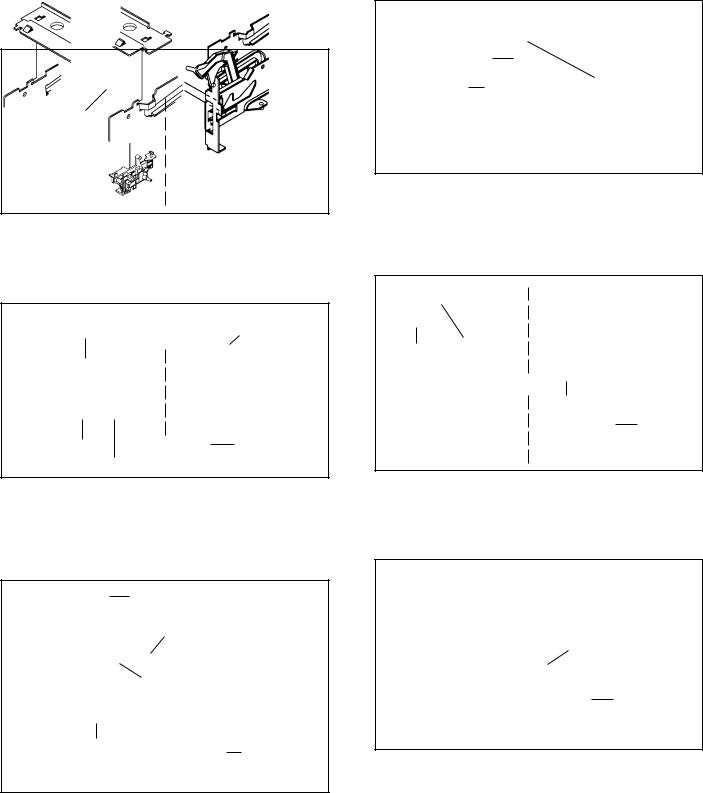
1-1: TOP CABINET AND FRONT CABINET (Refer to Fig. 1-1)
1.Remove the 5 screws 1.
2.Remove the Top Cabinet in the direction of arrow (A).
3.Disconnect the following connector: (CP651).
4.Unlock the 8 supports 2.
5.Remove the Front Cabinet in the direction of arrow (B).
6.Remove the 2 screws 3.
7.Remove the Operation PCB in the direction of arrow (C).
|
|
|
|
1 |
|
|
|
|
Top Cabinet |
|
|
|
|
1 |
|
|
|
1 |
|
|
|
|
|
1 |
|
|
|
|
(A) |
|
|
|
|
1 |
Front Cabinet |
|
|
|
|
2 |
2 |
(B) |
|
|
|
|
3 3 |
||
|
|
|
||
|
|
2 |
2 |
|
|
2 |
|
CP651 |
|
|
|
|
||
|
|
|
|
|
|
2 |
|
(C) |
|
|
|
|
|
|
|
|
2 |
2 |
Operation PCB |
|
|
|
Fig. 1-1 |
|
|
|
|
|
|
1-2: FLAP (Refer to Fig. 1-2) |
||||
1.Open Flap to 90˚ and flex in direction of arrow (A), at the same time slide in direction of arrow (B).
2.Then lift in direction of arrow (C).
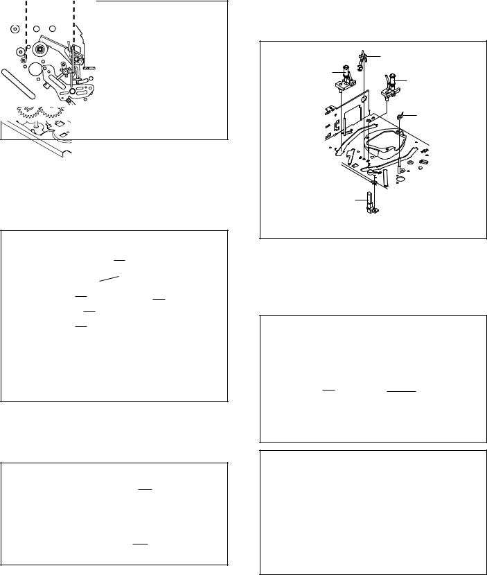
1-3: DECK CD (Refer to Fig. 1-3)
1.Make the short circuit on the position as shown Fig. 1-3 using a soldering. If you remove the Deck CD with no soldering, the Laser may be damaged.
2.Unlock the support 1 and remove the Deck Top Holder in the direction of arrow (A).
3.Remove the 2 screws 2.
4.Remove the 2 screws 3.
5.Disconnect the following connectors: (CP2301, CP2302, CP2601).
6.Remove the Deck CD in the direction of arrow (B).
7.Remove the 3 screws 4.
8.Remove the Front Angle in the direction of arrow (C).
|
|
|
Pick Up PCB |
|
|
3 |
|
|
Deck CD |
|
3 |
|
|
2 |
|
|
Deck Top Holder |
|
|
|
1 |
|
2 |
|
|
|
|
|
(A) |
|
Make the sort circuit |
|
|
(B) |
|
|
|
using a soldering. |
|
4 |
|
|
|
|
4 |
|
|
|
(C) |
CP2601 |
|
|
CP2301 |
|
|
|
|
|
|
|
|
CP2302 |
|
4 |
Front Angle |
|
|
|
|
Fig. 1-3 |
|
|
|
|
|
NOTE |
|
|
|
When the installation of the Deck CD, remove all the soldering on the short circuit position after the connection of Pick Up PCB and VCR/DVD PCB connector.
(A)
(C)
(B)
Flap
Fig. 1-2
1-1

DISASSEMBLY INSTRUCTIONS
1-4: VCR DECK (Refer to Fig. 1-4)
1. Remove the 3 screws 2.
2. Disconnect the following connectors: (CP101, CP102, CP103 and CP3001).
3. Remove the AC Head Cover and VCR Deck in the direction of arrow.
1 1
1
AC Head Cover
VCR Deck 

CP103 |
CP101 |
|
CP102 |
||
|
CP3001
Fig. 1-4
1-5: VCR/DVD PCB (Refer to Fig. 1-5)
1.Remove the screw 1.
2.Remove the 6 screws 2.
3.Remove the VCR/DVD PCB in the direction of arrow.
2
VCR/DVD PCB
1 2
 222
222  2
2
Fig. 1-5
1-2
DISASSEMBLY INSTRUCTIONS
2. REMOVAL OF VCR DECK PARTS
2-1: TOP BRACKET (Refer to Fig. 2-1)
1.Extend the 2 supports 1.
2.Slide the 2 supports 2 and remove the Top Bracket.
NOTE
1.After the installation of the Top Bracket, bend the support 1 so that the Top Bracket is fixed.
1 |
Top Bracket |
|
|
1 |
|
|
||
|
||
|
|
|
Top Bracket
2
2
Main Chassis
Main Chassis
Fig. 2-1
2-2: CASSETTE HOLDER ASS'Y (Refer to Fig. 2-2)
1.Move the Cassette Holder Ass'y to the front side.
2.Push the Locker R to remove the Cassette Side R.
3.Remove the Cassette Side L.
|
Cassette Side R |
|
Main Chassis |
|
Locker R |
|
|
|
Link Unit |
|
Main Chassis |
|
|
|
Cassette Side L |
|
Fig. 2-2 |
|
||
|
|
2-3: CASSETTE SIDE L/R (Refer to Fig. 2-3-A)
1.Remove the Locker Spring.
2.Unlock the 4 supports 1 and then remove the Cassette Side L/R.
3.Unlock the support 2 and then remove the Locker R.
Locker Spring
1
1Cassette Holder
2
Locker R
1
1
Cassette Side R
Cassette Side L
NOTE
1.In case of the Locker R installation, check if the one position of Fig. 2-3-B are correctly locked.
2.When you install the Cassette Side R, be sure to move the Locker R after installing.
Locker R |
|
|
Check if this position |
Cassette Side R |
is locked. |
|
Fig. 2-3-B
2-4: LINK UNIT (Refer to Fig. 2-4)
1.Set the Link Unit to the Eject position.
2.Unlock the support 1.
3.Remove the (A) side of the Link Unit first, then remove the (B) side.
Main Chassis
Link Unit
(A) |
(B) |
|
Link Unit
Main Chassis
Fig. 2-4
2-5: LINK LEVER/FLAP LEVER (Refer to Fig. 2-5)
1.Extend the support 1.
2.Remove the Link Lever.
3.Remove the Flap Lever.
Flap Lever
1
Link Lever
Fig. 2-5
Fig. 2-3-A
1-3
DISASSEMBLY INSTRUCTIONS
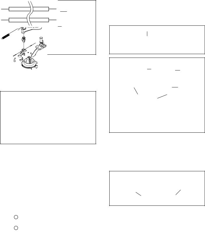
2-6: LOADING MOT OR/WORM (Refer to Fig. 2-6-A)
1.Remove the screw 1.
2.Remove the Loading Motor.
3.Remove the Worm.
Loading Motor
Worm
Main Chassis
• Screw Torque: 3 ± 0.5kgf•cm |
1 |
Fig. 2-6-A |
|
|
NOTE
1.In case of the Worm installation, check if the value of the Fig. 2-6-B is correct.
2.In case of the Loading Motor installation, hook the wire on the Cassette Opener as shown Fig. 2-6-C.
3.When installing the wires between Capstan DD Unit and Loading Motor, connect them correctly as shown Fig. 2-6-D.
19.2± 0.1mm
Safety surface for pressing
of the insert.
Fig. 2-6-B
|
|
|
|
|
|
|
Loading Motor |
|
|
|
|
|
|
|
|
||
|
|
|
|
|
|
|
Cassette Opener |
|
|
|
|
|
|
|
|||
|
|
|
|
|
|
|
|
Fig. 2-6-C |
|
|
|
|
|
|
|
|
|
|
|
|
|
|
||||
|
|
|
|
|
||||
|
|
Pink |
||||||
Loading |
Motor |
|
|
|
|
|
Capstan |
DD Unit |
- |
|
|
|
|
|
|
|
L2 |
|
|
|
|
|
|
|
||
+ |
|
|
|
|
|
|
|
L1 |
|
|
|
|
|
||||
|
|
White |
Fig. 2-6-D |
|||||
|
|
|
|
|
|
|
|
|
|
|
|
|
|
|
|
|
|
1-4
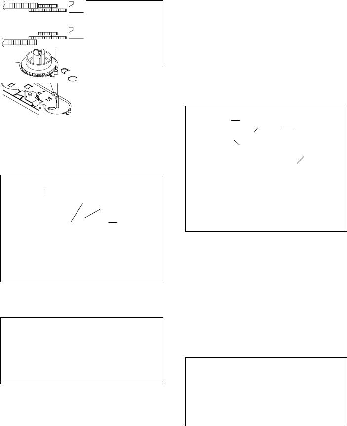
2-7: TENSION ASS’Y (Refer to Fig. 2-7-B)
1.Turn the Pinch Roller Cam clockwise so that the Tension Holder hook is set to the position of Fig. 2-7-A to move the Tension Arm Ass’y.
2.Remove the Tension Spring.
3.Unlock the 2 supports 1 and remove the Tension Band.
4.Unlock the support 2 and remove the Tension Arm Ass’y.
5.Unlock the support 3 and remove the Tension Connect.
6.Float the hook 4 and turn it clockwise then remove the Tension Holder.
Tension Arm Ass’y
Fig. 2-7-A
|
|
1 |
Tension Connect |
1 |
Tension Band |
|
|
|
|
3 |
|
Tension Spring
Tension Arm Ass’y
Tension Holder
2
4
Fig. 2-7-B
NOTE
1.In case of the Tension Band installation, note the direction of the installation. (Refer to Fig. 2-7-C)
2.In case of the Tension Band installation, install correctly as Fig. 2-7-D.
3.In case of the Tension Connect installation, install as the circled section of Fig. 2-7-E.
Tension Band
Tension Connect
Fig. 2-7-C
DISASSEMBLY INSTRUCTIONS
[OK] |
Tension Connect |
|
Tension Band |
[NG] |
Tension Connect |
|
|
|
|
Tension Band |
|
|
|
|
Fig. 2-7-D |
|
|
|
|
|
|
|
|
|
|
Tension Connect |
|
|
|
|
|
|
Main Chassis |
Fig. 2-7-E |
|
|
|
|||
|
|
|
||
|
|
|
|
|
|
|
|
|
|
2-8: T BRAKE ARM/T BRAKE BAND (Refer to Fig. 2-8-A)
1.Remove the T Brake Spring.
2.Turn the T Brake Arm clockwise and bend the hook section to remove it.
3.Unlock the 2 supports 1 and remove the T Brake Band.
T Brake Band
Hook section
T Brake Arm
1
1 |
T Brake Spring |
Fig. 2-8-A
NOTE
1.In case of the T Brake Band installation, install correctly as Fig. 2-8-B.
[OK] |
|
T Brake Arm |
T Brake Band |
|
|
|
|
|
[NG] |
|
T Brake Arm |
|
|
|
|
T Brake Band |
|
|
|
|
Fig. 2-8-B
2-9: S REEL/T REEL/IDLER ARM ASS’Y/IDLER GEAR (Refer to Fig. 2-9-A)
1.Remove the S Reel and T Reel.
2.Remove the 2 Polyslider Washers 1.
3.Remove the Idler Arm Ass’y and Idler Gear.
NOTE
1.Take care not to damage the gears of the S Reel and T Reel.
2.The Polyslider Washer may be remained on the back of the reel.
3.Take care not to damage the shaft.
4.Do not touch the section “A” of S Reel and T Reel. (Use gloves.) (Refer to Fig. 2-9-A) Do not adhere the stains on it.
5.When you install the reel, clean the shaft and grease it (FG-84M). (If you do not grease, noise may be heard in FF/REW mode.)
6.After installing the reel, adjust the height of the reel.
(Refer to MECHANICAL ADJUSTMENT)
Idler Gear
|
|
|
Idler Arm Ass’y |
|
|
S Reel |
(B) |
||
|
|
|
|
|
(A) |
|
|
T Reel |
|
1 |
|
|||
|
|
|
(A) |
|
|
|
|
|
|
|
|
|
|
|
1
Fig. 2-9-A
NOTE
1.In case of the S Reel and T Reel installation, check if the correct parts are installed. (Refer to Fig. 2-9-B)
2.In case of the Idler Arm Ass’y installation, install correctly as Fig. 2-9-C. And also set it so that the section “B” of Fig. 2-9-A is placed under the Main Chassis tab.
Big Hole |
Small Hole |
Fig. 2-9-B |
(S Reel) |
(T Reel) |
|
|
|
|
[OK]
Clutch Gear
Idler Arm Ass’y
[NG]
Idler Arm Ass’y
Clutch Gear
Fig. 2-9-C
1-5

DISASSEMBLY INSTRUCTIONS
2-10: CASSETTE OPENER/PINCH ROLLER BLOCK/P5 ARM ASS’Y (Refer to Fig. 2-10-A)
1. Unlock the support 1 and remove the Cassette Opener. 2. Remove the Pinch Roller Block and P5 Arm Ass’y.
1 |
|
|
|
|
|
Cassette Opener |
|
|
|
|
|
|
|||
|
|
|
|
|
|
|
|
|
|
|
|
|
Pinch Roller Block |
||
|
|
|
|
|
|||
|
|
|
|
|
P5 Arm Ass’y |
||
|
|
|
|
|
|||
|
|
|
|
|
|
|
Main Chassis |
|
|
|
|
|
|
|
|
Fig. 2-10-A
NOTE
1.Do not touch the Pinch Roller. (Use gloves.)
2.In case of the Pinch Roller Block and the Pinch Roller Cam installation, install correctly as Fig. 2-10-B.
Pinch Roller Block |
Can be seen the hole of |
|
|
|
the Pinch Roller Cam. |
P5 Arm Ass’y |
|
Can be seen the hole of the |
|
Main Cam. |
Fig. 2-10-B |
|
|
2-11: A/C HEAD (Refer to Fig. 2-11-A)
1.Remove the screw 1.
2.Remove the A/C Head Base.
3.Remove the 3 screws 2.
4.Remove the A/C Head and A/C Head Spring.
NOTE
1.Do not touch the A/C Head. (Use gloves.)
2.When you install the A/C Head Spring, install as shown in Fig. 2-11-B.
3.When you install the A/C Head, tighten the screw (1) first, then tighten the screw (2), finally tighten the screw (3).
|
(1) |
(3) |
|
|
|
2 |
|
2 |
2
(2) |
|
|
|
A/C Head |
|
|
|
|
|
||
1 |
|
|
A/C Head Spring |
||
|
|
||||
|
|
|
|
|
|
• Screw Torque: 5 ± 0.5kgf•cm (Screw 1) |
|
|
|
A/C Head Base |
|
|
|
|
|||
|
|
|
Fig. 2-11-A |
||
|
|
|
|
|
|
Spring Position |
Fig. 2-11-B |
|
2-12: FE HEAD (RECORDER ONLY) (Refer to Fig. 2-12)
1.Remove the screw 1.
2.Remove the FE Head.
 1
1
FE Head
• Screw Torque: 5 ± 0.5kgf•cm |
|
• The FE Head is not installed on the Video Cassette Player. |
Fig. 2-12 |
|
2-13: CYLINDER UNIT ASS’Y (Refer to Fig. 2-13)
1.Disconnect the following connector: (CD2001)
2.Remove the 3 screws 1.
3.Remove the Cylinder Unit Ass’y.
NOTE
1.When you install the Cylinder Unit Ass’y, tighten the screws from (1) to (3) in order while pulling the Ass’y toward the left front direction.
CD2001
Cylinder Unit Ass’y
(3)
(2) 1
(1)1
• Screw Torque: 3 ± 0.5kgf•cm |
1 |
|
Fig. 2-13 |
||
|
1-6
DISASSEMBLY INSTRUCTIONS
2-14: CAPSTAN DD UNIT (Refer to Fig. 2-14-A)
1.Remove the Capstan Belt.
2.Remove the 3 screws 1.
3.Remove the Capstan DD Unit.
Capstan Belt
Capstan DD Unit
1
1 1
• Screw Torque: 4 ± 0.5kgf•cm |
Fig. 2-14-A |
|
NOTE
1.In case of the Capstan DD Unit installation, apply the silicon bond (TSE3843-W) on the position Fig. 2-14-B correctly. (If no silicon bond applied, abnormal noise will be heard on the deck operation.)
(Refer to Fig. 2-14-B, C)
Applied position of silicon bond
Be careful not to apply the silicon bond to the Pinch Roller.
Fig. 2-14-B
Silicon Bond
Main Chassis
Capstan DD Unit
Fig. 2-14-C
2-15: MAIN CAM/PINCH ROLLER CAM/JOINT GEAR (Refer to Fig. 2-15-A)
1.Remove the E-Ring 1, then remove the Main Cam.
2.Remove the E-Ring 2, then remove the Pinch Roller Cam and Joint Gear.
1
Main Cam
2
Pinch Roller Cam
Joint Gear
Fig. 2-15-A
NOTE
1.In case of the Pinch Roller Cam and Main Cam installation, install them as the circled section of Fig. 2-15-B so that the each markers are met. (Refer to Fig. 2-15-B)
And also can be seen the Main Chassis hole through the Main Cam maker hole.
Pinch Roller Cam
Marker
Main Cam
Fig. 2-15-B
2-16: LOADING GEAR S/T UNIT (Refer to Fig. 2-16-A)
1.Remove the E-Ring 1 and remove the Main Loading Gear.
2.Remove the Main Rod, Tension Lever, Loading Arm S Unit and Loading Arm T Unit.
1
Main Loading Gear
Main Rod
Loading Arm T Unit
Tension Lever
Loading Arm S Unit
Fig. 2-16-A
1-7
DISASSEMBLY INSTRUCTIONS
NOTE
1.When you install the Loading Arm S Unit, Loading Arm T Unit and Main Loading Gear, align each marker. (Refer to Fig. 2-16-B)
Marker
Main Loading Gear
Marker
Loading Arm T Unit |
Loading Arm S Unit |
Fig. 2-16-B
2-17: CLUTCH ASS’Y/RING SPRING/CLUTCH LEVER/ CLUTCH GEAR (Refer to Fig. 2-17-A)
1.Remove the Polyslider Washer 1.
2.Remove the Clutch Ass’y and Ring Spring.
3.Remove the Clutch Lever.
4.Remove the Coupling Gear, Coupling Spring and Clutch Gear.
1
Clutch Ass’y
Ring Spring
Coupling Gear
Clutch Lever
Coupling Spring
Clutch Gear
Fig. 2-17-A
NOTE
1.In case of the Clutch Ass’y installation, install it with inserting the spring of the Clutch Ass’y into the dent of the Coupling Gear. (Refer to Fig. 2-17-B)
Clutch Ass’y
Coupling Gear
Fig. 2-17-B
1-8
2-18: CASSETTE GUIDE POST/INCLINED BASE S/T UNIT/P4 CAP (Refer to Fig. 2-18-A)
1.Remove the P4 Cap.
2.Unlock the support 1 and remove the Cassette Guide Post.
3.Remove the Inclined Base S/T Unit.
4.Remove the screw 2.
5.Remove the LED Reflector.
Cassette Guide Post
Inclined Base S |
1 |
|
|
Unit |
Inclined Base T |
|
|
|
Unit |
|
P4 Cap |
LED Reflector
 2
2
Fig. 2-18-A
NOTE
1.Do not touch the roller of Guide Roller.
2.In case of the P4 Cap installation, install it with parallel for “A” and “B” of Fig. 2-18-B.
3.In case of the Cassette Guide Post installation, install correctly as the circled section of Fig. 2-18-C.
“A” “B”
P4 Cap |
Cassette Opener |
|
Fig. 2-18-B
[OK]
Cassette Guide Post
[NG]
Cassette Guide Post
Fig. 2-18-C

DISASSEMBLY INSTRUCTIONS
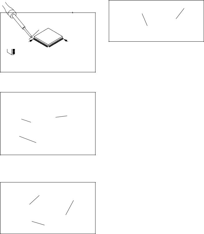
3.REMOVAL AND INSTALLATION OF FLAT PACKAGE IC
REMOVAL
1.Put the Masking Tape (cotton tape) around the Flat Package IC to protect other parts from any damage.
(Refer to Fig. 3-1.) NOTE
Masking is carried out on all the parts located within 10 mm distance from IC leads.
IC
Masking Tape
(Cotton Tape)
Fig. 3-1
2.Heat the IC leads using a blower type IC desoldering machine. (Refer to Fig. 3-2.)
NOTE
Do not add the rotating and the back and forth directions force on the IC, until IC can move back and forth easily after desoldering the IC leads completely.
Blower type IC desoldering machine
3.When IC starts moving back and forth easily after desoldering completely, pickup the corner of the IC using a tweezers and remove the IC by moving with the IC desoldering machine. (Refer to Fig. 3-3.)
NOTE
Some ICs on the PCB are affixed with glue, so be careful not to break or damage the foil of each IC leads or solder lands under the IC when removing it.
Blower type IC desoldering machine
Tweezers
IC
Fig. 3-3
4.Peel off the Masking Tape.
5.Absorb the solder left on the pattern using the Braided Shield Wire. (Refer to Fig. 3-4.)
NOTE
Do not move the Braided Shield Wire in the vertical direction towards the IC pattern.
Braided Shield Wire
Soldering Iron
IC
Fig. 3-2 |
IC pattern |
|
Fig. 3-4
1-9
DISASSEMBLY INSTRUCTIONS
INSTALLATION
1.Take care of the polarity of new IC and then install the new IC fitting on the printed circuit pattern. Then solder each lead on the diagonal positions of IC temporarily.
(Refer to Fig. 3-5.)
Soldering Iron
Solder temporarily |
Solder temporarily |
Fig. 3-5
2.Supply the solder from the upper position of IC leads sliding to the lower position of the IC leads.
(Refer to Fig. 3-6.)
Soldering Iron
Solder
IC |
Supply soldering |
|
from upper position |
|
to lower position |
Fig. 3-6
3.Absorb the solder left on the lead using the Braided Shield Wire. (Refer to Fig. 3-7.)
NOTE
Do not absorb the solder to excess.
4.When bridge-soldering between terminals and/or the soldering amount are not enough, resolder using a Thintip Soldering Iron. (Refer to Fig. 3-8.)
IC
Thin-tip Soldering Iron
Fig. 3-8
5.Finally, confirm the soldering status on four sides of the IC using a magnifying glass.
Confirm that no abnormality is found on the soldering position and installation position of the parts around the IC. If some abnormality is found, correct by resoldering.
NOTE
When the IC leads are bent during soldering and/or repairing, do not repair the bending of leads. If the bending of leads are repaired, the pattern may be damaged. So, be always sure to replace the IC in this case.
Soldering Iron
IC
Braided Shield Wire
Fig. 3-7
1-10
KEY TO ABBREVIATIONS
A |
A/C |
: |
Audio/Control |
|
H.SW |
: |
Head Switch |
|
ACC |
: |
Automatic Color Control |
|
Hz |
: |
Hertz |
|
AE |
: |
Audio Erase |
I |
IC |
: |
Integrated Circuit |
|
AFC |
: |
Automatic Frequency Control |
|
IF |
: |
Intermediate Frequency |
|
AFT |
: |
Automatic Fine Tuning |
|
IND |
: |
Indicator |
|
AFT DET |
: |
Automatic Fine Tuning Detect |
|
INV |
: |
Inverter |
|
AGC |
: |
Automatic Gain Control |
K |
KIL |
: |
Killer |
|
AMP |
: |
Amplifier |
L |
L |
: |
Left |
|
ANT |
: |
Antenna |
|
LED |
: |
Light Emitting Diode |
|
A.PB |
: |
Audio Playback |
|
LIMIT AMP |
: |
Limiter Amplifier |
|
APC |
: |
Automatic Phase Control |
|
LM, LDM |
: |
Loading Motor |
|
ASS’Y |
: |
Assembly |
|
LP |
: |
Long Play |
|
AT |
: |
All Time |
|
L.P.F |
: |
Low Pass Filter |
|
AUTO |
: |
Automatic |
|
LUMI. |
: |
Luminance |
|
A/V |
: |
Audio/Video |
M M |
: |
Motor |
|
B BGP |
: |
Burst Gate Pulse |
|
MAX |
: |
Maximum |
|
|
BOT |
: |
Beginning of Tape |
|
MINI |
: |
Minimum |
|
BPF |
: |
Bandpass Filter |
|
MIX |
: |
Mixer, mixing |
|
BRAKE SOL |
: |
Brake Solenoid |
|
MM |
: |
Monostable Multivibrator |
|
BUFF |
: |
Buffer |
|
MOD |
: |
Modulator, Modulation |
|
B/W |
: |
Black and White |
|
MPX |
: |
Multiplexer, Multiplex |
C C |
: |
Capacitance, Collector |
|
MS SW |
: |
Mecha State Switch |
|
|
CASE |
: |
Cassette |
N |
NC |
: |
Non Connection |
|
CAP |
: |
Capstan |
|
NR |
: |
Noise Reduction |
|
CARR |
: |
Carrier |
O OSC |
: |
Oscillator |
|
|
CH |
: |
Channel |
|
OPE |
: |
Operation |
|
CLK |
: |
Clock |
P |
PB |
: |
Playback |
|
CLOCK (SY-SE) |
: |
Clock (Syscon to Servo) |
|
PB CTL |
: |
Playback Control |
|
COMB |
: |
Combination, Comb Filter |
|
PB-C |
: |
Playback-Chrominance |
|
CONV |
: |
Converter |
|
PB-Y |
: |
Playback-Luminance |
|
CPM |
: |
Capstan Motor |
|
PCB |
: |
Printed Circuit Board |
|
CTL |
: |
Control |
|
P. CON |
: |
Power Control |
|
CYL |
: |
Cylinder |
|
PD |
: |
Phase Detector |
|
CYL-M |
: |
Cylinder-Motor |
|
PG |
: |
Pulse Generator |
|
CYL SENS |
: |
Cylinder-Sensor |
|
P-P |
: |
Peak-to Peak |
D |
DATA (SY-CE) |
: Data (Syscon to Servo) |
R |
R |
: |
Right |
|
|
dB |
: |
Decibel |
|
REC |
: |
Recording |
|
DC |
: |
Direct Current |
|
REC-C |
: |
Recording-Chrominance |
|
DD Unit |
: Direct Drive Motor Unit |
|
REC-Y |
: |
Recording-Luminance |
|
|
DEMOD |
: |
Demodulator |
|
REEL BRK |
: |
Reel Brake |
|
DET |
: |
Detector |
|
REEL S |
: |
Reel Sensor |
|
DEV |
: |
Deviation |
|
REF |
: |
Reference |
E |
E |
: |
Emitter |
|
REG |
: |
Regulated, Regulator |
|
EF |
: |
Emitter Follower |
|
REW |
: |
Rewind |
|
EMPH |
: |
Emphasis |
|
REV, RVS |
: |
Reverse |
|
ENC |
: |
Encoder |
|
RF |
: |
Radio Frequency |
|
ENV |
: |
Envelope |
|
RMC |
: |
Remote Control |
|
EOT |
: |
End of Tape |
|
RY |
: |
Relay |
|
EQ |
: |
Equalizer |
S |
S. CLK |
: |
Serial Clock |
|
EXT |
: |
External |
|
S. COM |
: |
Sensor Common |
F |
F |
: |
Fuse |
|
S. DATA |
: |
Serial Data |
|
FBC |
: |
Feed Back Clamp |
|
SEG |
: |
Segment |
|
FE |
: |
Full Erase |
|
SEL |
: |
Select, Selector |
|
FF |
: |
Fast Forward, Flipflop |
|
SENS |
: |
Sensor |
|
FG |
: |
Frequency Generator |
|
SER |
: |
Search Mode |
|
FL SW |
: |
Front Loading Switch |
|
SI |
: |
Serial Input |
|
FM |
: |
Frequency Modulation |
|
SIF |
: |
Sound Intermediate Frequency |
|
FSC |
: |
Frequency Sub Carrier |
|
SO |
: |
Serial Output |
|
FWD |
: |
Forward |
|
SOL |
: |
Solenoid |
G GEN |
: |
Generator |
|
SP |
: |
Standard Play |
|
|
GND |
: |
Ground |
|
STB |
: |
Serial Strobe |
H |
H.P.F |
: |
High Pass Filter |
|
SW |
: |
Switch |
|
|
|
|
|
|
|
1-11 |
|
|
|
KEY TO ABBREVIATIONS |
S |
SYNC |
: |
Synchronization |
|
SYNC SEP |
: |
Sync Separator, Separation |
T |
TR |
: |
Transistor |
|
TRAC |
: |
Tracking |
|
TRICK PB |
: |
Trick Playback |
|
TP |
: |
Test Point |
U UNREG |
: |
Unregulated |
|
V |
V |
: |
Volt |
|
VCO |
: |
Voltage Controlled Oscillator |
|
VIF |
: |
Video Intermediate Frequency |
|
VP |
: |
Vertical Pulse, Voltage Display |
|
V. PB |
: |
Video Playback |
|
VR |
: |
Variable Resistor |
|
V.REC |
: |
Video Recording |
|
VSF |
: |
Visual Search Fast Forward |
|
VSR |
: |
Visual Search Rewind |
|
VSS |
: |
Voltage Super Source |
|
V-SYNC |
: |
Vertical-Synchronization |
|
VT |
: |
Voltage Tuning |
X |
X’TAL |
: |
Crystal |
Y |
Y/C |
: |
Luminance/Chrominance |
1-12

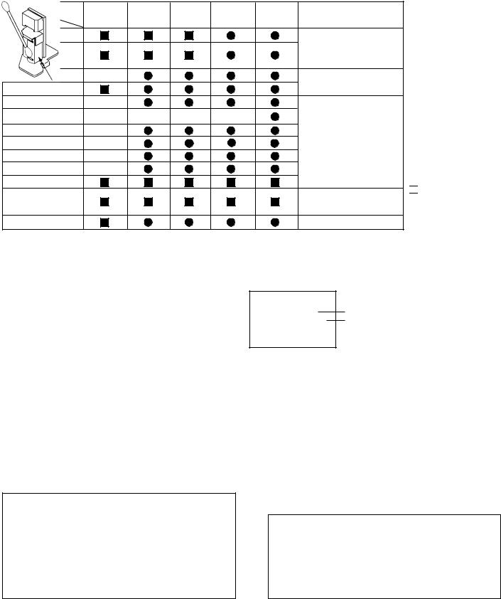
SERVICE MODE LIST
This unit provided with the following SERVICE MODES so you can repair, examine and adjust easily.
To enter to the SERVICE MODE function, press and hold both buttons simultaneously on the main unit or on the main unit and on the remote control for more than a standard time (second).
Set Key |
|
Set Key |
Standard Time |
Operations |
|
|
(seconds) |
|
|||
|
|
||||
|
|
|
|
|
|
|
|
|
|
|
|
|
|
|
|
PLAY/REC total hours are displayed on the TV Monitor. |
|
|
|
|
|
Refer to the “PREVENTIVE CHECKS AND SERVICE INTERVALS” |
|
|
|
|
|
|
|
CH UP |
|
FF |
2 |
(CONFIRMATION OF HOURS USED). |
|
|
|
||||
|
|
|
|||
|
|
|
|
Can be checked of the INITIAL DATA of MEMORY IC. |
|
|
|
|
|
|
|
|
|
|
|
|
|
|
|
|
|
Refer to the “WHEN REPLACING EEPROM (MEMORY) IC”. |
|
|
|
|
|
|
|
CH UP |
|
STOP |
2 |
Adjust the SWITHCHING POINT automatically. |
|
|
|
||||
|
Refer to the “ELECTRICAL ADJUSTMENT” (SWITHCHING POINT). |
|
|||
|
|
|
|
|
|
|
|
|
|
|
|
|
|
|
|
Initialization of the factory on VCR. |
|
|
|
|
|
|
|
CH UP |
|
PLAY |
2 |
NOTE: Do not use this for the normal servicing. |
|
|
If you set a factory initialization, the memories are reset such as |
|
|||
|
|
||||
|
|
|
|
|
|
|
|
|
|
the clock setting, the channel setting, and PLAY/REC total hours. |
|
|
|
|
|
|
|
|
|
|
|
|
|
|
|
|
|
VCR operation mode at no connection of DVD. |
|
|
|
|
|
|
|
CH DOWN |
|
POWER |
2 |
Refer to the “PREPARATION FOR SERVICING” |
|
|
|
||||
|
|
|
|
NOTE: Although the DVD is connected, the DVD mode cannot be selected. |
|
|
|
|
|
|
|
|
|
|
|
|
|
Set Key |
|
Remocon Key |
Standard Time |
Operations |
|
||||
|
(seconds) |
|||
|
|
|
|
|
|
|
|
|
|
|
|
|
|
Initialization of the factory on DVD. |
|
|
|
|
|
REC |
|
4 |
2 |
NOTE: The function will only work without the setting of DVD disc at DVD |
|
mode. |
|||
|
|
|
|
|
|
|
|
|
Do not use this for the normal servicing. |
|
|
|
|
|
|
|
|
|
|
|
|
|
|
Releasing of PARENTAL LOCK. |
|
|
|
|
|
STOP |
|
7 |
3 |
Refer to the “PARENTAL CONTROL - RATING LEVEL”. |
|
||||
|
||||
|
NOTE: The function will only work without the setting of DVD disc at DVD |
|||
|
|
|
|
|
|
|
|
|
mode. |
|
|
|
|
|
|
|
|
|
|
<NOTE> WHEN "N" IS ALWAYS BEING DISPLAYED ON THE TV MONITOR.
(REMOTE CONTROLLER FORMAT)
This product is usable the remote controller which is used by DVD+VHS of the other brand.
If "N" is always being displayed on the TV monitor, can not control from provided remote controller since this product is other brand format.
•How to return a JVC format.
Turn off the power of the set and push the CHANNEL+ button and the REC button of the set simultaneously.
PARENTAL CONTROL - RATING LEVEL (4 DIGIT PASSWORD CANCELLATION)
If the stored 4 digit password in the Rating Level menu needs to be cancelled, please follow the steps below.
1.Turn Unit ON.
2.Press and hold the '7' key on the remote control unit.
3.Simultaneously press and hold the 'STOP' key on the front panel.
4.Hold both keys for more than 3 seconds.
5.The On Screen Display message 'PASSWORD CLEAR' will appear.
6.The 4 digit password has now been cleared.
1-13
WHEN REPLACING EEPROM (MEMORY) IC
If a service repair is undertaken where it has been required to change the MEMORY IC, the following steps should be taken to ensure correct data settings while making reference to TABLE 1.
NOTE: No need setting for after INI 2F.
INI |
+0 |
+1 |
+2 |
+3 |
+4 |
+5 |
+6 |
|
+7 |
|
+8 |
+9 |
+A |
+B |
+C |
+D |
+E |
+F |
|
ADDRESS DATA |
||||
|
|
|
|
|
|
|
|
|||||||||||||||||
|
|
|
|
|
|
|
|
|||||||||||||||||
|
|
|
|
|
|
|
|
|
|
|
|
|
|
|
|
|
|
|
|
|
|
|
|
|
00 |
0E |
30 |
BA |
60 |
64 |
64 |
4A |
|
86 |
|
0B |
2B |
86 |
32 |
8A |
08 |
0A |
0F |
|
INIT 00 |
0E |
|||
|
|
|
|
|
|
|
|
|
|
|
|
|
|
|
|
|
|
|
|
|||||
|
|
|
|
|
|
|
|
|
|
|
|
|
|
|
|
|
|
|
||||||
10 |
AF |
97 |
95 |
8A |
A0 |
55 |
31 |
|
04 |
|
88 |
A5 |
9F |
3A |
00 |
10 |
BF |
00 |
|
PLAY/REC |
0003 |
|||
|
|
|
|
|
|
|
|
|
|
|
|
|
|
|
|
|
|
|
|
|
|
|
|
|
20 |
3A |
11 |
22 |
70 |
61 |
2A |
3A |
|
00 |
|
00 |
00 |
00 |
85 |
A2 |
B0 |
00 |
00 |
|
|
|
|
|
|
|
|
|
|
|
|
|
|
|
|
|
|
|
|
|
|
|
|
|
|
|
|
|
|
|
|
|
|
|
|
|
|
|
|
|
|
|
|
|
|
|
|
|
|
|
Fig. 1 |
|
|
||
|
|
|
|
|
|
|
|
Table 1 |
|
|
|
|
|
|
|
|
|
|
|
|||||
|
|
|
|
|
|
|
|
|
|
|
|
|
|
|
|
|
|
|
|
|
|
|||
1.Connect the set to TV Monitor.
2.Turn on the POWER.
3.Press both CH UP button on the set and the FF button on the set for more than 2 seconds. ADDRESS and DATA will appear on TV Monitor as Fig 1.
4.ADDRESS is now selected and should “blink”. Using the SET + or - button on the remote, step through the ADDRESS until required ADDRESS to be changed is reached.
5.Press ENTER to select DATA. When DATA is selected, it will “blink”.
6.Again, step through the DATA using SET + or - button until required DATA value has been selected.
7.Pressing ENTER will take you back to ADDRESS for further selection if necessary.
8.Repeat steps 4 to 7 until all data has been checked.
9.When satisfied correct DATA has been entered, turn POWER off (return to STANDBY MODE) to finish DATA input.
After the data input, set to the initializing of shipping.
10.Turn on the POWER.
11.Press both CH UP button on the set and the PLAY button on the set for more than 2 seconds.
12.After the finishing of the initializing of shipping, the unit will turn off automatically.
The unit will now have the correct DATA for the new MEMORY IC.
1-14
PREVENTIVE CHECKS AND SERVICE INTERVALS
The following standard table depends on environmental conditions and usage. Parts replacing time does not mean the life span for individual parts.
Also, long term storage or misuse may cause transformation and aging of rubber parts. The following list means standard hours, so the checking hours depends on the conditions.
Time |
500 |
1,000 |
1,500 |
2,000 |
2,500 |
Notes |
|
Parts Name |
hours |
hours |
hours |
hours |
hours |
||
|
|||||||
Audio Control Head |
|
|
|
|
|
Clean those parts in |
|
Full Erase Head |
|
|
|
|
|
||
|
|
|
|
|
contact with the tape. |
||
(Recorder only) |
|
|
|
|
|
||
|
|
|
|
|
|
||
Capstan Belt |
|
|
|
|
|
Clean the rubber, and parts |
|
Pinch Roller |
|
|
|
|
|
which the rubber touches. |
|
Capstan DD Unit |
|
|
|
|
|
|
|
Loading Motor |
|
|
|
|
|
|
|
Tension Band |
|
|
|
|
|
|
|
T Brake Band |
|
|
|
|
|
|
|
Clutch Ass’y |
|
|
|
|
|
|
|
Idler Arm Ass’y |
|
|
|
|
|
|
|
Capstan Shaft |
|
|
|
|
|
|
|
Tape Running |
|
|
|
|
|
Replace when rolling |
|
Guide Post |
|
|
|
|
|
becomes abnormal. |
|
Cylinder Unit |
|
|
|
|
|
Clean the Head |

 : Clean
 : Check it and if necessary, replace it.
CONFIRMATION OF HOURS USED
PLAY/REC total hours can be checked on the FIP.
Total hours are displayed in 16 system of notation.
NOTE: If you set a factory initialization, the total hours is reset to “0”.
1.Connect the set to TV Monitor.
2.Turn on the POWER.
3.Press both CH UP button on the set and the FF button on the set for more than 2 seconds.
4.After the confirmation of using hours, turn off the power.
CLEANING
NOTE
After cleaning the heads with isopropyl alcohol, do not run a tape until the heads dry completely. If the heads are not completely dry and alcohol gets on the tape, damage may occur.
1. AUDIO CONTROL HEAD
Clean the Audio Control Head with the cotton stick soaked by alcohol. Clean the full erase head in the same manner. (Refer to the figure below.)
INIT 00 0E Initial setting content of MEMORY IC. PLAY/REC 0003 PLAY/REC total hours.
= (16 x 16 x 16 x thousands digit value)
+(16 x 16 x hundreds digit value)
+(16 x tens digit value)
+(ones digit value)
2.TAPE RUNNING SYSTEM
When cleaning the tape transport system, use the gauze moistened with isopropyl alcohol.
3. CYLINDER
Wrap a piece of chamois around your finger. Dip it in isopropyl alcohol. Hold it to the cylinder head softly.
Turn the cylinder head counterclockwise to clean it (in the direction of the arrow). (Refer to the figure below.)
NOTE
Do not exert force against the cylinder head. Do not move the chamois upward or downward on the head.
Use the chamois one by one.
Cylinder Head
Audio Control Head
1-15

SERVICING FIXTURES AND TOOLS
(4 heads model) |
Torque Gauge |
Roller Driver |
X-JG153 X Value Adjustment |
VHS Alignment Tape |
PUJ48075-2 |
PTU94002-2 |
Screwdriver |
MHP |
|
|
|
|
|
|
|
|
|
|
|
|
|
|
|
|
|
|
|
|
|
|
|
|
|
|
|
|
|
|
|
|
|
|
|
|
|
|
|
|
|
|
|
Torque Tape |
Short Jumper |
|
|
|
|
||||
|
|
|
|
|
|
|
|
|
|
|
|
|
|
|
|
|
|
|
|
MECHANISM ADJUSTMENT PARTS LOCATION GUIDE
4
5
3
2
1
10 |
9 |
8 |
1.Tension Connect
2.Tension Arm
3.Guide Roller
4.Audio/Control Head
5.X value adjustment driver hole
6.P4 Post
7.T Brake Spring
8.T Reel
9.S Reel
10.Adjusting section for the Tension Arm position
1-16
6
7
MECHANICAL ADJUSTMENTS
TAPE REMOVAL METHOD AT NO POWER SUPPLY
1.Remove the Top Cabinet, Front Cabinet and DVD Block.
(Refer to item 1 of the DISASSEMBLY INSTRUCTIONS.)
2.Remove the screw 1 of the Deck Chassis and remove the Loading Motor. (Refer to Fig. 2)
3.Rotate the Pinch Roller Cam in the direction of the arrow by hand to slacken the Video Tape.
4.Rotate the Clutch Ass'y either of the derections to wind the Video Tape in the Cassette Case.
5.Repeat the above step 3~4. Then take out the Video Cassette from the Deck Chassis.
Be careful not to scratch on the tape.
Loading Motor
Screw 1
Capstan DD Unit
Pinch Roller Cam
Main Cam
Clutch Ass'y
Main Chassis (Front Side)
DISC REMOVAL METHOD AT NO POWER SUPPLY
1.Remove the Top Cabinet and Front Cabinet. (Refer to item
1 of the DISASSEMBLY INSTRUCTIONS.)
2.Rotate the gear of Deck CD section in the direction of the arrow by hand, remove the disc from Deck CD.
Gear
Deck CD
1. CONFIRMATION AND ADJUSTMENT
Read the following NOTES before starting work.
•Place an object which weighs between 450g~500g on the Cassette Tape to keep it steady when you want to make the tape run without the Cassette Holder. (Do not place an object which weighs over 500g.)
1-1: CONFIRMATION AND ADJUSTMENT OF TENSION POST POSITION
1.Set to the PLAY mode.
2.Adjust the adjusting section for the Tension Arm position so that the Tension Arm top is within the standard line of Main Chassis.
3.While turning the S Reel clockwise, confirm that the edge of the Tension Arm is located in the position described above.
Standard line of Main Chassis
Tension Arm
0.5mm (Adjusting range)
Fig. 1-1-A
Adjusting section for the
Tension Arm position
Tension Band
The Tension Arm top will |
The Tension Arm top will |
move to the inside direction |
move to the outside direction |
of the Main Chassis. |
of the Main Chassis. |
|
Bend |
|
Fig. 1-1-B |
1-2: CONFIRMATION OF PLAYBACK TORQUE AND BACK TENSION TORQUE DURING PLAYBACK
1.After confirmation and adjustment of Tension Post position (Refer to item 1-1), load the cassette type torque tape and set to the PLAY mode.
2.Confirm that the right meter of the torque tape indicates 50~90gf•cm during playback in SP mode.
3.Confirm that the left meter of the torque tape indicates 25~40gf•cm during playback in SP mode.
1-3: CONFIRMATION OF VSR TORQUE
1.Install the Torque Gauge on the S Reel. Set to the Picture Search (Rewind) mode. (Refer to Fig.1-2-B)
2.Then, confirm that it indicates 120~180gf•cm.
NOTE
Install the Torque Gauge on the reel disk firmly. Press the REW button to turn the reel disk.
1-17
MECHANICAL ADJUSTMENTS
1-4: CONFIRMATION OF REEL BRAKE TORQUE
(S Reel Brake) (Refer to Fig. 1-2-B)
1.Once set to the Fast Forward mode then set to the Stop mode. While, unplug the AC cord when the Pinch Roller Block is on the position of Fig. 1-2-A.
2.Move the Idler Ass’y from the S Reel.
3.Install the Torque Gauge on the S Reel. Turn the Torque Gauge clockwise.
4.Then, confirm that it indicates 60~100gf•cm.
(T Reel Brake) (Refer to Fig. 1-2-B)
1.Once set to the Fast Forward mode then set to the Stop mode. While, unplug the AC cord when the Pinch Roller Block is on the position of Fig. 1-2-A.
2.Move the Idler Ass’y from the T Reel.
3.Install the Torque Gauge on the T reel. Turn the Torque Gauge counterclockwise.
4.Then, confirm that it indicates 30~50gf•cm.
The position at FF mode.
Pinch Roller Block
Stop at this position.
Cassette Opener
The position at STOP mode.
Capstan DD Unit
Cassette Holder Ass’y
Fig. 1-2-A
Torque Gauge
Torque Gauge
S Reel
T Reel
Fig. 1-2-B
NOTE
If the torque is out of the range, replace the following parts.
Check item |
Replacement Part |
1-3 |
Idler Ass’y/Clutch Ass’y |
|
|
1-4 |
S Reel side: S Reel/Tension Band/Tension |
|
Connect/Tension Arm Ass’y |
|
T Reel side: T Reel/T Brake Band//T Brake |
|
Spring/T Brake Arm |
|
|
2.CONFIRMATION AND ADJUSTMENT OF TAPE RUNNING MECHANISM
Tape Running Mechanism is adjusted precisely at the factory. Adjustment is not necessary as usual. When you replace the parts of the tape running mechanism because of long term usage or failure, the confirmation and adjustment are necessary.
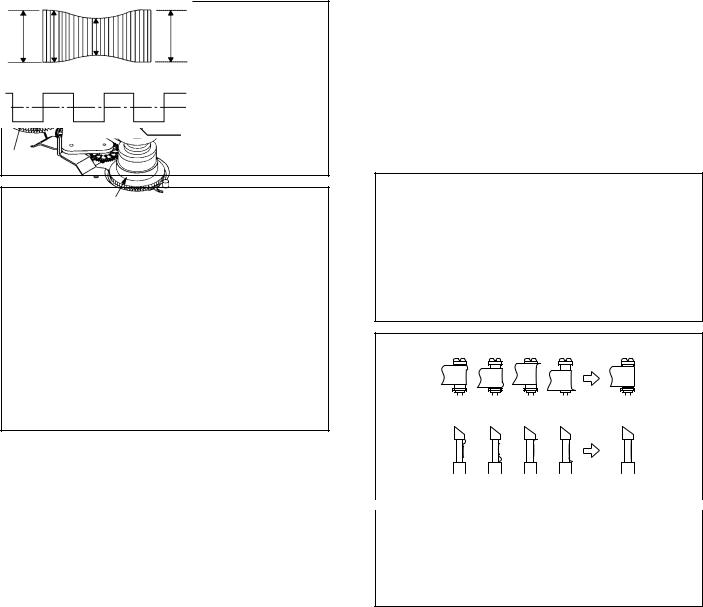
2-1: GUIDE ROLLER
1.Playback the VHS Alignment Tape (MHP).
2.Connect CH-1 of the oscilloscope to TP101 (Envelope) and CH-2 to TP3002 (SW Pulse).
3.Press and hold the Tracking-Auto button on the remote control more than 2 seconds to set tracking to center.
4.Trigger with SW Pulse and observe the envelope. (Refer to Fig. 2-1-A)
5.When observing the envelope, adjust the Roller Driver (PTU94002-2) slightly until the envelope will be flat. Even if you press the Tracking Button, adjust so that flatness is not moved so much. (Refer to Fig. 2-1-B)
6.Adjust so that the A : B ratio is better than 3 : 2 as shown in Fig. 2-1-C, even if you press the Tracking Button to move the envelope (The envelope waveform will begin to decrease when you press the Tracking Button).
7.Adjust the PG shifter during playback.
(Refer to the ELECTRICAL ADJUSTMENTS)
NOTE
After adjustment, confirm and adjust A/C head.
(Refer to item 2-2)
CH-1 Envelope (TP101)
CH-1 CH-2
Track Track
CH-2
SW Pulse (TP3002)
Fig. 2-1-A
Improper |
Proper |
(a) Guide roller
|
(b) P4 Cap |
|
Fig. 2-1-B |
||
|
|
|
|
|
|
|
|
|
|
|
|
|
|
|
|
|
|
|
Entrance |
|
Exit |
||
Max |
|
|
|
|
|
|
A |
|
B |
Max |
|
|
|
|
|
|
|
A : B ≥ 3 : 2
Fig. 2-1-C
1-18
MECHANICAL ADJUSTMENTS
2-2: CONFIRMATION AND ADJUSTMENT OF AUDIO/ CONTROL HEAD
When the Tape Running Mechanism does not work well, adjust the following items.
1.Playback the VHS Alignment Tape (MHP).
2.Confirm that the reflected picture of stamp mark is appeared on the tape prior to P4 Post as shown in Fig. 2- 2-A.
a)When the reflected picture is distorted, turn the screw 1 clockwise until the distortion is disappeared.
b)When the reflected picture is not distorted, turn the screw 1 counterclockwise until little distortion is appeared, then adjust the a).
3.Turn the screw 2 to set the audio level to maximum.
4.Confirm that the bottom of the Audio/ Control Head and the bottom of the tape is shown in Fig. 2-2-C.
c)When the height is not correct, turn the screw 3 to adjust the height. Then, adjust the 1~3 again.
Audio/Control Head
Reflected picture of
Stamp Mark
P4 Cap
Stamp Mark |
Fig. 2-2-A |
|
Audio/Control Head
31
2
4
Fig. 2-2-B
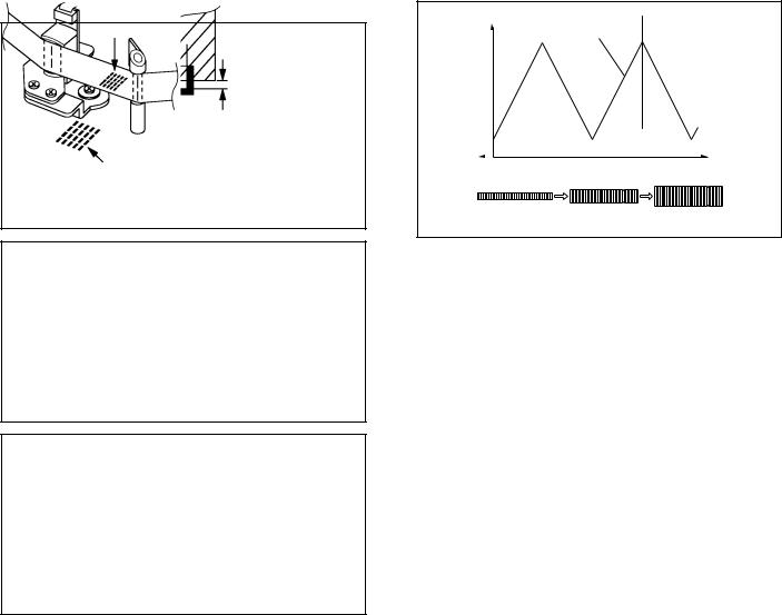
2-3: TAPE RUNNING ADJUSTMENT
(X VALUE ADJUSTMENT)
1.Confirm and adjust the position of the Tension Post.
(Refer to item 1-1)
2.Adjust the Guide Roller. (Refer to item 2-1)
3.Confirm and adjust the Audio/Control Head.
(Refer to item 2-2)
4.Connect CH-1 of the oscilloscope to TP3002, CH-2 to
TP101 and CH-3 to Audio Out.
5.Playback the VHS Alignment Tape (MHP).
6.Press and hold the Tracking-Auto button on the remote control more than 2 seconds to set tracking to center.
7.Set the X Value adjustment driver (X-JG153) to the 4 of Fig. 2-2-B. At first, turn the Audio/Control Head position fully toward the capstan side. Then adjust X Value to turn it back gradually toward the cylinder side and stop on the second peak point position of the envelope.
output |
Play MHP |
|
|
|||
|
|
|
|
|||
Waveform |
|
|
|
|
||
|
|
|
|
|
|
|
|
|
|
|
X-value adjustment point |
|
|
|
|
|
|
|
|
|
Drum side |
Control head position |
Capstan side |
||||
Maximum
Fig. 2-3
8.Perform tracking operation and confirm the envelope is maximum on the tracking center position.
9.Playback the VHS Alignment Tape (MHP-L).
10.Perform tracking operation and confirm the envelope is maximum on the tracking center position. If envelope is
not maximum, should be fine-tune the X-VALUE.
Audio/Control Head
Tape
0.25±0.05mm
Fig. 2-2-C
1-19

ELECTRICAL ADJUSTMENTS
Read and perform this adjustment when repairing the circuits or replacing electrical parts or PCB assemblies.
1. BASIC ADJUSTMENT
CAUTION
When you exchange IC and Transistor for a heat sink, apply the silicon grease (YG6260M) on the contact section of the heat sink. Before applying new silicon grease, remove all the old silicon grease. (Old grease may cause damages to the IC and Transistor.)
1-1: SWITCHING POINT
CONDITIONS
MODE-PLAYBACK
Input Signal-Alignment Tape (MHP)
INSTRUCTIONS
1.Connect CH-1 on the oscilloscope to TP3002 and CH-2 to TP8001.
2.Playback the alignment tape. (MHP)
3.Press and hold the Tracking-Auto button on the remote control more than 2 seconds to set tracking to center.
4.Press both CH UP button on the set and the STOP button on the set for more than 2 seconds.
CH-2
6.5H
CH-1
Fig. 1-1-A
CH-2
CH-1
6.5H
Fig. 1-1-B
ELECTRICAL ADJUSTMENT PARTS LOCATION GUIDE (Connector Connections)
TU301
J8001 |
J8007 |
OS8001 |
J8006 |
SW7001 |
J8008 |
TP8001
CP102
CD501
AC IN
|
|
|
CD102 |
|
FE HEAD |
|
|
CP103 |
|
|
AC HEAD |
|
|
|
|
TP3001 |
|
|
|
TP101 |
|
|
|
TP3002 |
|
|
|
J8003 |
J8004 |
J8005 |
OS651 |
V651
VCR/DVD PCB
CP681
OPERATION PCB
TP101 : Envelope
TP3001 : Service Mode
TP3002 : Switching Pulse
TP8001 : Switching Point
CP2601
CP2301
CP2302
CP651
CD2601
CD681
CD2302 |
CD2301 |
DECK CD
1-20
IC DESCRIPTIONS
VCR/DVD PCB OEC0132A (IC3001)
No. |
PORT |
PIN NAME |
I/O |
DESCRIPRION |
1 |
SVSS |
SVSS |
- |
Ground. |
2 |
CTL_REF |
CTL_REF |
|
Output terminal for CTL amp REF (1/2 SVCC) |
3 |
CTL-H(+) |
CTL-H(+) |
|
Input and output terminal of Control Head. |
4 |
CTL-H(-) |
CTL-H(-) |
|
Input terminal of Control Head. |
5 |
CTL_BIAS |
CTL_BIAS |
|
Output terminal for bias. |
6 |
CTL_FB |
CTL_FB |
|
Input terminal for CTL feedback |
7 |
CTL_AMP(O) |
CTL_AMP(O) |
|
Output terminal for amp out. |
8 |
CTL_AMP(I) |
CTL_AMP(I) |
|
Input terminal for CTL shumit amp . |
9 |
CFG |
CFG |
|
Input terminal for CAPSTAN FG signal detection. |
10 |
SVCC |
SVCC |
|
+ 5V (Servo) |
11 |
AFC_PC |
AFC_PC |
|
AFC oscilator (external circuit). |
12 |
AFC_OSC |
AFC_OSC |
|
AFC oscilator (external circuit). |
13 |
AFC_LPF |
AFC_LPF |
|
LPF connection for AFC OSC. |
14 |
CSYN/HSYN |
CSYNC |
OUT |
Output terminal for composite SYNC. |
15 |
VLPF/VSYN |
VSYNC |
IN |
Input terminal for composite SYNC.(from 14pin) |
16 |
CV_IN2 |
CV_IN2 |
IN |
Composite Video input terminal.(for data slicer) |
17 |
CV_IN1 |
CV_IN1 |
IN |
Composite Video input terminal.(for OSD) |
18 |
OSD VCC |
OSDVCC |
- |
+ 5V |
19 |
CV_OUT |
CV_OUT |
OUT |
Composite Video output.(with OSD) |
20 |
OSD_VSS |
OSD_VSS |
- |
Ground. |
21 |
4/2 FSC_OUT |
4/2 FSC_OUT |
OUT |
4 FSC pulse. |
22 |
4/2 FSC_IN |
4/2 FSC_IN |
IN |
4 FSC pulse. |
23 |
AVSS |
AVSS |
- |
Ground. |
24 |
AN-B |
VIDEO_ENV |
IN |
Input terminal of video RF envelope. |
25 |
AN-A |
BOT-H |
IN |
Tape start sensor input signal. |
26 |
AN-9 |
EOT-H |
IN |
Tape end sensor input signal. |
27 |
AN8 |
MS_SEN-B |
IN |
Input terminal of mecha state sensor. |
28 |
P07/AN7 |
MS_SEN-A |
IN |
|
29 |
P06/AN6 |
KEY-B |
IN |
Main unit key input. |
30 |
P05/AN5 |
KEY-A |
IN |
|
31 |
P04/AN4 |
STEREO_SEL |
IN |
Input terminal for the judgement of voice reception condition. |
32 |
P03/AN3 |
HI-FI_ENV |
IN |
Input terminal of HiFi RF envelope. |
33 |
P02/AN2 |
AFT-S_CURVE |
IN |
AFT S CURVE input for tuner. |
34 |
P01/AN1 |
SERVICE |
IN |
Input terminal for Service Mode. |
35 |
P00/AN0 |
TAB SW |
IN |
Input terminal for judge the tape if it has TAB or not. |
36 |
AVCC |
AVCC |
- |
ON/OFF control Micon AD section. |
37 |
P10/IRQ0 |
POWER_FAIL |
IN |
Input terminal of Power fail signal. |
38 |
P11/IRQ1 |
VIDEO MUTE H |
OUT |
H for at AUTO_CLOCK in POWER OFF. |
39 |
P12/IRQ2 |
POWER ON L |
OUT |
For control the user power switch ON/OFF. |
1-21
IC DESCRIPTIONS
VCR/DVD PCB OEC0132A (IC3001)
40 |
P13/IRQ3 |
REEL-S |
IN |
Input terminal of reel sensor supply. |
41 |
P14/IRQ4 |
REEL-T |
IN |
Input terminal of reel sensor take up. |
42 |
P15/IRQ5 |
POWER ON-H |
OUT |
For control the user power switch ON/OFF. |
43 |
P16/IC |
REM_IN |
IN |
Receive the remote control signal. |
44 |
P17/TMOW |
DVD RESET |
OUT |
For control the DVD RESET. |
45 |
P67/RP7/TMB |
DVD POWER CTL |
OUT |
Output terminal for DVD power CTL.(3.3V/9V) |
46 |
P66/RP6/ADTRG |
DVD LED |
OUT |
The DVD LED light-up/put-off control output. |
47 |
P65/RP5 |
VCR LED |
OUT |
The VCR LED light-up/put-off control output. |
48 |
P64/RP4 |
1G/T-REC LED |
OUT |
LEM(LED Module) control terminal. |
49 |
P63/RP3 |
2G/REC LED |
OUT |
LEM(LED Module) control terminal. |
50 |
P62/RP2 |
3G/TV/VCR LED |
OUT |
LEM(LED Module) control terminal. |
51 |
P61/RP1 |
4G |
OUT |
LEM(LED Module) control terminal. |
52 |
P60/RP0 |
5G |
OUT |
LEM(LED Module) control terminal. |
53 |
P37/TM0 |
Y/C CLOCK |
OUT |
Control terminal for Y/C. (CLOCK). |
54 |
P36/BUZZ |
Y/C DATA |
OUT |
Control terminal for Y/C.(DATA). |
55 |
P35 |
SEG1 |
OUT |
LEM(LED Module) control terminal. |
|
|
|
|
|
56 |
VCC |
VCC |
- |
Power of CPU. |
57 |
VSS |
VSS |
- |
Ground. |
58 |
P27 |
SEG2 |
OUT |
LEM(LED Module) control terminal. |
|
|
|
|
|
59 |
P26 |
SEG3 |
OUT |
LEM(LED Module) control terminal. |
60 |
P25 |
SEG4 |
OUT |
LEM(LED Module) control terminal. |
61 |
P24/SCL1 |
IIC CLK |
OUT |
CLOCK terminal for IIC BUS communication. |
62 |
P23/SDA1 |
IIC DATA |
OUT |
DATA terminal for IIC BUS communication. |
63 |
P22/SCK1 |
SEG5 |
OUT |
LEM(LED Module) control terminal. |
64 |
P21/SO1 |
SO1/TX |
OUT |
Input terminal for DVD communication.(asynchronous) |
65 |
P20/SI1 |
SI1/RX |
IN |
Output terminal for DVD communication.(asynchronous) |
66 |
P47/RPTRG |
SEG6 |
OUT |
LEM(LED Module) control terminal. |
67 |
P46/FTOB |
SEG7 |
OUT |
LEM(LED Module) control terminal. |
68 |
P45/FTOA |
SEG8 |
OUT |
LEM(LED Module) control terminal. |
69 |
P44/FTID |
NC |
OUT |
Not used. |
70 |
P43/FTIC |
NC |
OUT |
Not used. |
71 |
P42/FTIB |
SEG9 |
OUT |
LEM(LED Module) control terminal. |
72 |
P41/FTIA |
NC |
OUT |
Not used. |
73 |
P40/PWM14 |
SEG10 |
OUT |
LEM(LED Module) control terminal. |
74 |
FEW |
FEW |
IN |
FZTAT Write protect. |
75 |
X2 |
X2 |
OUT |
Subclock pulse(32.768KHz) |
76 |
X1 |
X1 |
IN |
|
77 |
/RESET |
/RESET |
IN |
RESET will be done when the voltage goes to HIGH after the |
|
|
|
|
reset signal. |
78 |
OSC1 |
OSC1 |
IN |
Connect the main crystal(10MHz) |
1-22
IC DESCRIPTIONS
VCR/DVD PCB OEC0132A (IC3001)
79 |
VSS |
VSS |
- |
Ground. |
80 |
OSC2 |
OSC2 |
OUT |
Connect the main crystal(10MHz) |
81 |
VCL |
VCL |
IN |
Connect the capacitor |
82 |
MD0 |
MD0 |
IN |
FZTAT Write MODE. |
83 |
P34/PWM2 |
NC |
OUT |
not used. |
84 |
P33/PWM1 |
CAP_LIMIT |
OUT |
Switch the maximum output current of the Capstan Motor. |
85 |
P32/PWM0 |
TUNER AUDIO MUTE-H |
OUT |
Output low at tuner and output high at external input/play. |
86 |
P31/SV2 |
VCR-H |
OUT |
H for at PLAY in VCR MODE. L for except above case. |
87 |
P30/SV1 |
POWER_MUTE |
OUT |
audio mute at POWER ON/OFF. |
88 |
P70/PPG0 |
SYS_MUTE |
OUT |
audio mute for DVD at POWER ON/OFF. |
89 |
P71/PPG1 |
NC |
OUT |
Not used. |
90 |
P72/PPG2 |
NC |
OUT |
Not used. |
91 |
P73/PPG3 |
AV SW_2 |
OUT |
Control rear/front video signal.(at AV X 2) |
92 |
P74/PPG4/RP8 |
AV SW_1 |
OUT |
Control DVD/VCR video/audio signal. |
93 |
P75/PPG5/RP9 |
Y/C CS |
OUT |
Control terminal for Y/C. (CHIP SELECT). |
94 |
P76/PPG6/RPA |
RF CH SW |
OUT |
3/4 ch Selection for the RF CH. |
95 |
P77/RPG7/RPB |
AUDIO_MUTE-H |
OUT |
L for at AUDIO MUTE and POWER OFF. H for except above case. |
96 |
P80/YCO |
V_REC_ST-H |
OUT |
On control of A/V recording(Whole width erase) circuit. |
97 |
P81/EXCAP/YBO |
LDM CTL |
OUT |
Loading motor control terminal. |
98 |
P82/EXCTL |
CAP_FWD-H |
OUT |
Capstan forward and backward command. |
99 |
P83/C,ROT/R |
C.ROTARY |
OUT |
Color Rotary Control output. |
100 |
P84/H.AMP/SW/G |
H.AMP.SW |
OUT |
Switching output of Head Amp SW. |
101 |
P85/COMP/B |
COMP |
IN |
Comparison results input of Playback Envelope level on SP/LP |
|
|
|
|
heads (4 heads). |
102 |
P85/EZTTRG |
CAP_FULL |
OUT |
Output the HIGH during the acceleration force of capstan motor at |
|
|
|
|
SLOW mode. |
103 |
P87/DPG |
CYL_SPEED_UP |
OUT |
Output terminal for correct cylinder during SLOW. |
104 |
DFG |
D FG/PG |
IN |
Input terminal for DRUM FG signal detection. |
105 |
VIDEO_FF |
VIDEO_H.SW |
OUT |
Output terminal of Video Head SW. |
106 |
AUDIO_FF |
HI-FI H.SW |
OUT |
Output terminal of HI-FI Head SW. |
107 |
DRUM_PWM |
DRUM_PWM |
OUT |
PWM output of Cylinder control. |
108 |
CAP_PWM |
CAP_PWM |
OUT |
PWM output of Capastan control. |
109 |
V-PULSE |
DUMMY_V-SYNC |
OUT |
Virtual V Pulse output. |
110 |
SV VSS |
SV VSS |
- |
Ground. |
111 |
C.SYNC_IN |
SYNC |
IN |
Input terminal for composite SYNC. |
112 |
VCC |
VCC(SV) |
- |
+ 5V |
1-23

SERVO TIMING CHART
VCR/DVD PCB IC3001 (OEC0132A)
DPG 104 PIN
DFG 104 PIN
24 Cycle
H. SW. P 105 PIN |
|
CH 1 |
CH 2 |
|
V-SYNC (E-E) 111 PIN
REC CTL (REC) 7 PIN
V-SYNC (TRICK PB) 109 PIN
• WAVEFORM CHANGES DEPENDED ON THE TAPE SPEED
1-24

MECHANISM TIMING CHART
Please see the list below for the operational timing and the mode sensor output of the main parts on each mechanism modes.
MECHANISM MODE |
|
EJECT |
STBY |
UNLOAD |
STOP3 |
VSR |
F.SLOW |
PB |
STOP2 |
FF/REW |
|
Mode Dealing |
|
|
|
|
|
|
|
|
|
|
|
Directions |
|
|
|
|
|
|
|
|
|
|
|
Revolutional Angle of |
0 |
3 |
15 |
100 |
206.3 |
226.4 |
255 |
272.2 |
303.7 |
323.8 |
|
MAIN CAM |
|
||||||||||
|
|
|
|
|
|
|
|
|
|
|
|
Moving Quantity of |
|
|
|
0 |
18 |
21.5 |
26.5 |
29.5 |
35 |
38.5 |
|
MAIN ROD (mm) |
|
|
|
||||||||
|
|
|
|
|
|
|
|
|
|
||
MODE |
HIGH |
|
|
|
|
|
|
|
|
|
|
MS-1 |
|
|
|
|
|
|
|
|
|
|
|
SENSOR |
LOW |
|
|
|
|
|
|
|
|
|
|
Output |
|
|
|
|
|
|
|
|
|
|
|
|
HIGH |
|
|
|
|
|
|
|
|
|
|
|
MS-2 |
|
|
|
|
|
|
|
|
|
|
|
LOW |
|
|
|
|
|
|
|
|
|
|
INCLINED BASE S/T UNIT |
|
|
|
|
|
|
PRESS |
|
|
|
|
PINCH ROLLER BLOCK |
|
|
|
|
|
|
PRESS |
|
|
|
|
P5 ARM ASS'Y |
|
|
(T BRAKE:LOW) |
|
|
P5-ON (T BRAKE HIGH) |
|
|
|||
TENSION LEVER |
|
|
|
|
|
|
|
S BRAKE:HIGH |
|
||
|
|
|
|
|
|
S BRAKE:LOW |
|
|
|
|
|
TENSION ARM ASS'Y |
|
|
|
|
|
BRAKE-ON |
|
|
|
||
(S REEL BRAKE) |
|
|
|
|
|
|
|
|
|
|
|
TENSION CONNECT |
|
|
|
BRAKE-ON |
|
|
|
|
|
|
|
(S REEL BRAKE) |
|
|
|
|
|
|
|
|
|
|
|
|
|
|
|
|
|
|
|
|
|
|
BRAKE-ON |
T BRAKE ARM |
|
|
|
|
BRAKE-ON |
|
|
|
|
|
|
(T REEL BRAKE) |
|
|
|
|
|
|
|
|
|
|
|
CLUTCH LEVER |
|
|
|
CLUTCH-ON |
|
|
|
|
DIRECT |
||
LINK UNIT |
|
|
|
|
|
PRESS |
|
|
|
|
|
|
|
|
|
UP |
|
|
|
|
|
|
|
FLAP LEVER |
|
|
|
|
|
|
|
|
|
|
|
1-25
TROUBLESHOOTING GUIDE
(VCR SECTION)
POWER DOES NOT TURN ON
Does display light? |
NO |
Is the voltage |
NO |
Check of T501 |
||
|
|
linked to L506? |
|
|
and peripheral circuit. |
|
|
|
|
|
|
||
YES |
|
|
YES |
|
|
|
|
|
|
|
|
||
|
|
|
|
|
|
|
|
|
|
Check of V651 |
|
|
|
|
|
|
and peripheral circuit. |
|
|
|
Is the voltage at |
|
|
|
|
|
|
|
NO |
|
|
|
|
|
|
|
|
|
Check IC3001. |
||
pin 30 of IC 3001 |
|
|
|
|
|
|
|
|
|
|
|
|
|
0V? |
|
|
|
|
|
|
|
|
|
|
|
|
|
YES |
|
|
|
|
|
|
Check of T501 and peripheral circuit.
1-26
 Loading...