

Page 1

Operators and Safety Manual
Model
450A
450AJ
3120868
April 24, 2002
Page 2

Page 3
FOREWORD
f
FOREWORD
The purpose of this manual is to provide users with the operating procedures essential for the promotion o
proper machine operation for its intended purpose. It is important to over-stress proper machine usage. All
information in this manual should be READ and UNDERSTOOD before any attempt is made to operate the
machine. YOUR OPERATING MANUAL IS YOUR MOST IMPORTANT TOOL - Keep it with the machine.
REMEMBER ANY EQUIPMENT IS ONLY AS SAFE AS THE OPERATOR.
BECAUSE THE MANUFACTURER HAS NO DIRECT CONTROL OVER MACHINE APPLICATION AND
OPERATION, PROPER SAFETY PRACTICES ARE THE RESPONSIBILITY OF THE USER AND HIS OPERATING PERSONNEL.
ALL INSTRUCTIONS IN THIS MANUAL ARE BASED ON THE USE OF THE MACHINE UNDER PROPER
OPERATING CONDITIONS, WITH NO DEVIATIONS FROM THE ORIGINAL DESIGN. ALTERATION AND/OR
MODIFICATION OF THE MACHINE IS STRICTLY FORBIDDEN, WITHOUT WRITTEN APPROVAL FROM
JLG INDUSTRIES, PER OSHA REGULATIONS AND APPLICABLE ANSI STANDARDS.
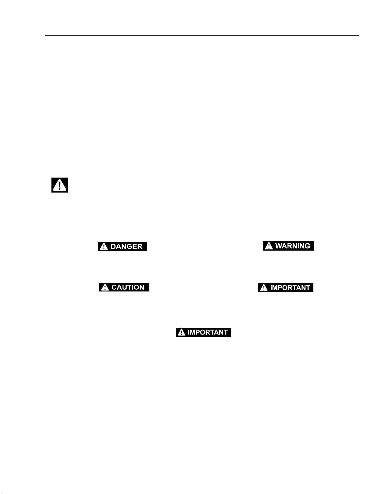
THIS SAFETY ALERT SYMBOL IS USED TO CALL ATTENTION TO POTENTIAL HAZARDS WHICH
MAY LEAD TO SERIOUS INJURY OR DEATH IF IGNORED.
Safety of personnel and proper use of the machine are of primary concern, DANGER, WARNING, CAUTION, IMPORTANT, INSTRUCTIONS and NOTE are inserted throughout this manual to emphasize these
areas. They are defined as follows:
DANGER INDICATES AN IMMINENTLY HAZARDOUS SITUATION
WHICH, IF NOT AVOIDED WILL RESULT IN SERIOUS INJURY OR
DEATH.]
CAUTION INDICATES A POTENTIALLY HAZARDOUS SITUATION
WHICH, IF NOT AVOIDED, MAY RESULT IN MINOR OR MODERATE
INJURY. IT MAY ALSO BE USED TO ALERT AGAINST UNSAFE
PRACTICES
WARNING INDICATES A POTENTIALLY HAZARDOUS SITUATION
WHICH, IF NOT AVOIDED COULD RESULT IN SERIOUS INJURY
OR DEATH.
IMPORTANT OR INSTRUCTIONS INDICATES A PROCEDURES
ESSENTIAL FOR SAFE OPERATION AND WHICH, IF NOT FOLLOWED, MAY RESULT IN A MALFUNCTION OR DAMAGE TO THE
MACHINE.
JLG INDUSTRIES MAY HAVE ISSUED SAFETY RELATED BULLETINS FOR YOUR JLG PRODUCT. CONTACT JLG INDUSTRIES INC.
OR THE LOCAL AUTHORIZED JLG DISTRIBUTOR FOR INFORMATION CONCERNING SAFETY RELATED BULLETINS WHICH MAY
HAVE BEEN ISSUED FOR YOUR JLG PRODUCT. ALL ITEMS REQUIRED BY THE SAFETY RELATED BULLETINS MUST BE COMPLETED ON THE AFFECTED JLG PRODUCT
Due to continuous product improvements, JLG Industries, Inc. reserves the right to make specification changes without prior notification. Contact JLG Industries, Inc. for updated information.
3120868 – JLG Lift – a
Page 4

FOREWORD
This page left blank intentionally.
b – JLG Lift – 3120868
Page 5

FOREWORD
All procedures herein are based on the use of the
machine under proper operating conditions, with no
deviations from original design intent... as per OSHA
regulations.
READ & HEED!
The ownership, use, service, and/or maintenance of
this machine is subject to various governmental and
local laws and regulations. It is the responsibility of
the owner/user to be knowledgeable of these laws
and regulations and to comply with them. The most
prevalent regulations of this type in the United States
are the Federal OSHA Safety Regulations*. Listed
below, in abbreviated form are some of the requirements of Federal OSHA regulations in effect as of the
date of publication of this handbook.
The listing of these requirements shall not relieve
the owner/user of the responsibility and obligation
to determine all applicable laws and regulations and
their exact wording and requirements, and to comply with the requirements. Nor shall the listing of
these requirements constitute an assumption of
responsibility of liability on the part of JLG Industries, Inc.
1. Only trained and authorized operators shall be
permitted to operate the aerial lift.
2. A malfunctioning lift shall be shut down until
repaired.
3. The controls shall be plainly marked as to their
function.
4. The controls shall be tested each day prior to
use to determine that they are in safe operating
condition.
5. All personnel in the platform shall, at all times,
wear approved fall protection devices and
other safety gear as required.
6. Load limits specified by the manufacturer shall
not be exceeded.
7. Instruction and warning placards must be legible.
8. Aerial lifts may be field modified for uses other
than those intended by the manufacturer only if
certified in writing by the manufacturer to be in
conformity to JLG requirements and to be at
least as safe as it was prior to modification.
9. Aerial lifts shall not be used near electric power
lines unless the lines have been de energized
or adequate clearance is maintained.
10. Employees using aerial lifts shall be instructed
on how to recognize and avoid unsafe conditions and hazards.
11. Ground controls shall not be operated unless
permission has been obtained from personnel
in the platform, except in case of an emergency.
12. Regular inspection of the job site and aerial lift
shall be performed by competent persons.
13. Personnel shall always stand on the floor of the
platform, not on boxes, planks, railing or other
devices, for a work position.
*Applicable Federal OSHA regulations for the
United States, as of the date of publication of this
manual, include, but are not limited to, 29 CFR
1910.67, 29 CFR 1926.20, 29 CFR 1926.21, 29 CFR
1926.28, and 29 CFR 1926.453.
3120868 – JLG Lift – c
Page 6

FOREWORD
REVISON LOG
Original Issue - May, 1998
Revised - August 1, 1999
2-12 and 2-13 - Updated 11-2-99
5-3 - Updated 2-16-00
3-6 - Updated 9-19-00
3-10 - Updated 4-24-02
d – JLG Lift – 3120868
Page 7

TABLE OF CONTENTS
TABLE OF CONTENTS
SUBJECT - SECTION, PARAGRAPH PAGE NO.
SECTION - FOREWORD
SECTION 1 - SAFETY PRECAUTIONS
1.1 General . . . . . . . . . . . . . . . . . . . . . . . . . . . . . . . . . . . . . . . . . . . . . . . . . . . . . . . . . . . . . . . . . . . . . .1-1
1.2 Driving/Towing. . . . . . . . . . . . . . . . . . . . . . . . . . . . . . . . . . . . . . . . . . . . . . . . . . . . . . . . . . . . . . . . .1-1
1.3 Electrocution Hazard. . . . . . . . . . . . . . . . . . . . . . . . . . . . . . . . . . . . . . . . . . . . . . . . . . . . . . . . . . . . 1-2
1.4 Pre-Operational . . . . . . . . . . . . . . . . . . . . . . . . . . . . . . . . . . . . . . . . . . . . . . . . . . . . . . . . . . . . . . . .1-2
1.5 Driving . . . . . . . . . . . . . . . . . . . . . . . . . . . . . . . . . . . . . . . . . . . . . . . . . . . . . . . . . . . . . . . . . . . . . . .1-4
1.6 Operation. . . . . . . . . . . . . . . . . . . . . . . . . . . . . . . . . . . . . . . . . . . . . . . . . . . . . . . . . . . . . . . . . . . . . 1-5
1.7 Towing and Hauling . . . . . . . . . . . . . . . . . . . . . . . . . . . . . . . . . . . . . . . . . . . . . . . . . . . . . . . . . . . .1-8
SECTION 2 - PREPARATION AND INSPECTION
2.1 General . . . . . . . . . . . . . . . . . . . . . . . . . . . . . . . . . . . . . . . . . . . . . . . . . . . . . . . . . . . . . . . . . . . . . .2-1
2.2 Preparation For Use . . . . . . . . . . . . . . . . . . . . . . . . . . . . . . . . . . . . . . . . . . . . . . . . . . . . . . . . . . . .2-1
2.3 Delivery and Frequent Inspection . . . . . . . . . . . . . . . . . . . . . . . . . . . . . . . . . . . . . . . . . . . . . . . . . .2-1
2.4 Daily Walk-Around Inspection. . . . . . . . . . . . . . . . . . . . . . . . . . . . . . . . . . . . . . . . . . . . . . . . . . . . .2-5
2.5 Daily Functional Check . . . . . . . . . . . . . . . . . . . . . . . . . . . . . . . . . . . . . . . . . . . . . . . . . . . . . . . . . .2-9
2.6 Battery Maintenance . . . . . . . . . . . . . . . . . . . . . . . . . . . . . . . . . . . . . . . . . . . . . . . . . . . . . . . . . . . .2-10
SECTION 3 - USER RESPONSIBILITIES AND MACHINE CONTROL
3.1 General . . . . . . . . . . . . . . . . . . . . . . . . . . . . . . . . . . . . . . . . . . . . . . . . . . . . . . . . . . . . . . . . . . . . . .3-1
3.2 Personnel Training . . . . . . . . . . . . . . . . . . . . . . . . . . . . . . . . . . . . . . . . . . . . . . . . . . . . . . . . . . . . .3-1
3.3 Operating Characteristics and Limitations . . . . . . . . . . . . . . . . . . . . . . . . . . . . . . . . . . . . . . . . . . . 3-2
3.4 Controls and Indicators. . . . . . . . . . . . . . . . . . . . . . . . . . . . . . . . . . . . . . . . . . . . . . . . . . . . . . . . . .3-5
3.5 Placards and Decals . . . . . . . . . . . . . . . . . . . . . . . . . . . . . . . . . . . . . . . . . . . . . . . . . . . . . . . . . . . .3-11
SECTION 4 - MACHINE OPERATION
4.1 Description . . . . . . . . . . . . . . . . . . . . . . . . . . . . . . . . . . . . . . . . . . . . . . . . . . . . . . . . . . . . . . . . . . .4-1
4.2 General . . . . . . . . . . . . . . . . . . . . . . . . . . . . . . . . . . . . . . . . . . . . . . . . . . . . . . . . . . . . . . . . . . . . . .4-1
4.3 Engine Operation . . . . . . . . . . . . . . . . . . . . . . . . . . . . . . . . . . . . . . . . . . . . . . . . . . . . . . . . . . . . . .4-2
4.4 Traveling (Driving) . . . . . . . . . . . . . . . . . . . . . . . . . . . . . . . . . . . . . . . . . . . . . . . . . . . . . . . . . . . . . .4-2
4.5 Steering . . . . . . . . . . . . . . . . . . . . . . . . . . . . . . . . . . . . . . . . . . . . . . . . . . . . . . . . . . . . . . . . . . . . . .4-3
4.6 Parking and Stowing . . . . . . . . . . . . . . . . . . . . . . . . . . . . . . . . . . . . . . . . . . . . . . . . . . . . . . . . . . . .4-3
4.7 Platform . . . . . . . . . . . . . . . . . . . . . . . . . . . . . . . . . . . . . . . . . . . . . . . . . . . . . . . . . . . . . . . . . . . . . . 4-3
4.8 Boom . . . . . . . . . . . . . . . . . . . . . . . . . . . . . . . . . . . . . . . . . . . . . . . . . . . . . . . . . . . . . . . . . . . . . . . .4-4
4.9 Lift Up and Platform Level Down Disable Switch Functional Check . . . . . . . . . . . . . . . . . . . . . . . 4-5
4.10 Shut Down and Park . . . . . . . . . . . . . . . . . . . . . . . . . . . . . . . . . . . . . . . . . . . . . . . . . . . . . . . . . . . . 4-5
4.11 Tie Down and Lifting . . . . . . . . . . . . . . . . . . . . . . . . . . . . . . . . . . . . . . . . . . . . . . . . . . . . . . . . . . . .4-5
4.12 Oscillating Axle Lockout Test (If Equipped) . . . . . . . . . . . . . . . . . . . . . . . . . . . . . . . . . . . . . . . . . .4-9
4.13 Towing . . . . . . . . . . . . . . . . . . . . . . . . . . . . . . . . . . . . . . . . . . . . . . . . . . . . . . . . . . . . . . . . . . . . . . .4-10
SECTION 5 - OPTIONAL EQUIPMENT
5.1 Dual Fuel System (Gas Engine Only) . . . . . . . . . . . . . . . . . . . . . . . . . . . . . . . . . . . . . . . . . . . . . . .5-1
5.2 Oscillating Axle . . . . . . . . . . . . . . . . . . . . . . . . . . . . . . . . . . . . . . . . . . . . . . . . . . . . . . . . . . . . . . . .5-1
5.3 Platform W/soft Touch Proximity System Bumper . . . . . . . . . . . . . . . . . . . . . . . . . . . . . . . . . . . . .5-1
5.4 Four Wheel Drive. . . . . . . . . . . . . . . . . . . . . . . . . . . . . . . . . . . . . . . . . . . . . . . . . . . . . . . . . . . . . . .5-1
5.5 Cold Weather Package . . . . . . . . . . . . . . . . . . . . . . . . . . . . . . . . . . . . . . . . . . . . . . . . . . . . . . . . . .5-1
5.6 Travel Alarm . . . . . . . . . . . . . . . . . . . . . . . . . . . . . . . . . . . . . . . . . . . . . . . . . . . . . . . . . . . . . . . . . . .5-2
5.7 Electric Generator . . . . . . . . . . . . . . . . . . . . . . . . . . . . . . . . . . . . . . . . . . . . . . . . . . . . . . . . . . . . . .5-2
5.8 Rotating Beacon . . . . . . . . . . . . . . . . . . . . . . . . . . . . . . . . . . . . . . . . . . . . . . . . . . . . . . . . . . . . . . .5-2
5.9 Cylinder Bellows . . . . . . . . . . . . . . . . . . . . . . . . . . . . . . . . . . . . . . . . . . . . . . . . . . . . . . . . . . . . . . .5-2
5.10 Boom Wipers . . . . . . . . . . . . . . . . . . . . . . . . . . . . . . . . . . . . . . . . . . . . . . . . . . . . . . . . . . . . . . . . . .5-2
5.11 Hostile Environment Package. . . . . . . . . . . . . . . . . . . . . . . . . . . . . . . . . . . . . . . . . . . . . . . . . . . . .5-3
5.12 Motion Alarm . . . . . . . . . . . . . . . . . . . . . . . . . . . . . . . . . . . . . . . . . . . . . . . . . . . . . . . . . . . . . . . . . .5-3
3120868 – JLG Lift – i
Page 8

TABLE OF CONTENTS (Continued)
TABLE OF CONTENTS (continued)
SUBJECT - SECTION, PARAGRAPH PAGE NO.
5.13 Semi-Track . . . . . . . . . . . . . . . . . . . . . . . . . . . . . . . . . . . . . . . . . . . . . . . . . . . . . . . . . . . . . . . . . . .5-3
SECTION 6 - EMERGENCY PROCEDURES
6.1 General . . . . . . . . . . . . . . . . . . . . . . . . . . . . . . . . . . . . . . . . . . . . . . . . . . . . . . . . . . . . . . . . . . . . . . 6-1
6.2 Emergency Towing Procedures . . . . . . . . . . . . . . . . . . . . . . . . . . . . . . . . . . . . . . . . . . . . . . . . . . .6-1
6.3 Emergency Controls and Their Locations . . . . . . . . . . . . . . . . . . . . . . . . . . . . . . . . . . . . . . . . . . .6-1
6.4 Emergency Operation . . . . . . . . . . . . . . . . . . . . . . . . . . . . . . . . . . . . . . . . . . . . . . . . . . . . . . . . . . . 6-2
6.5 Incident Notification. . . . . . . . . . . . . . . . . . . . . . . . . . . . . . . . . . . . . . . . . . . . . . . . . . . . . . . . . . . . .6-2
SECTION 7 - INSPECTION AND REPAIR LOG
LIST OF FIGURES
FIGURE NO. TITLE PAGE NO.
2-1. Machine Nomenclature . . . . . . . . . . . . . . . . . . . . . . . . . . . . . . . . . . . . . . . . . . . . . . . . . . . . . . . . . . 2-3
2-2. Daily Walk-Around Inspection - Sheet 1 of 3 . . . . . . . . . . . . . . . . . . . . . . . . . . . . . . . . . . . . . . . . .2-6
2-3. Daily Walk-Around Inspection - Sheet 2 of 3 . . . . . . . . . . . . . . . . . . . . . . . . . . . . . . . . . . . . . . . . .2-7
2-4. Daily Walk-Around Inspection - Sheet 3 of 3 . . . . . . . . . . . . . . . . . . . . . . . . . . . . . . . . . . . . . . . . .2-8
2-5. Lubrication Diagram . . . . . . . . . . . . . . . . . . . . . . . . . . . . . . . . . . . . . . . . . . . . . . . . . . . . . . . . . . . . 2-11
2-6. Torque Chart . . . . . . . . . . . . . . . . . . . . . . . . . . . . . . . . . . . . . . . . . . . . . . . . . . . . . . . . . . . . . . . . . .2-14
3-1. Position of Least Forward Stability . . . . . . . . . . . . . . . . . . . . . . . . . . . . . . . . . . . . . . . . . . . . . . . . .3-3
3-2. Position of Least Backward Stability. . . . . . . . . . . . . . . . . . . . . . . . . . . . . . . . . . . . . . . . . . . . . . . .3-4
3-3. Ground Control Indicator Panel . . . . . . . . . . . . . . . . . . . . . . . . . . . . . . . . . . . . . . . . . . . . . . . . . . . 3-6
3-4. Ground Control Station . . . . . . . . . . . . . . . . . . . . . . . . . . . . . . . . . . . . . . . . . . . . . . . . . . . . . . . . . . 3-7
3-5. Platform Station. . . . . . . . . . . . . . . . . . . . . . . . . . . . . . . . . . . . . . . . . . . . . . . . . . . . . . . . . . . . . . . .3-9
3-6. Danger and Warning Decal Location . . . . . . . . . . . . . . . . . . . . . . . . . . . . . . . . . . . . . . . . . . . . . . . 3-12
3-7. Control Panel Symbols - Sheet 1 of 2. . . . . . . . . . . . . . . . . . . . . . . . . . . . . . . . . . . . . . . . . . . . . . .3-15
3-8. Control Panel Symbols - Sheet 2 of 2. . . . . . . . . . . . . . . . . . . . . . . . . . . . . . . . . . . . . . . . . . . . . . .3-16
4-1. Grade and Sideslope . . . . . . . . . . . . . . . . . . . . . . . . . . . . . . . . . . . . . . . . . . . . . . . . . . . . . . . . . . .4-3
4-2. Functional Check . . . . . . . . . . . . . . . . . . . . . . . . . . . . . . . . . . . . . . . . . . . . . . . . . . . . . . . . . . . . . .4-5
4-3. Machine Tie Down - A Models . . . . . . . . . . . . . . . . . . . . . . . . . . . . . . . . . . . . . . . . . . . . . . . . . . . .4-6
4-4. Machine Tie Down - AJ Models . . . . . . . . . . . . . . . . . . . . . . . . . . . . . . . . . . . . . . . . . . . . . . . . . . .4-7
4-5. Lifting Chart . . . . . . . . . . . . . . . . . . . . . . . . . . . . . . . . . . . . . . . . . . . . . . . . . . . . . . . . . . . . . . . . . . .4-8
4-6. Drive Disconnect Hub . . . . . . . . . . . . . . . . . . . . . . . . . . . . . . . . . . . . . . . . . . . . . . . . . . . . . . . . . . .4-10
LIST OF TABLES
TABLE NO. TITLE PAGE NO.
1-1 Minimum Safe Approach Distances (M.S.A.D.) to energized (exposed or insulated)
power lines and parts . . . . . . . . . . . . . . . . . . . . . . . . . . . . . . . . . . . . . . . . . . . . . . . . . . . . . .1-2
2-1 Lubrication Chart. . . . . . . . . . . . . . . . . . . . . . . . . . . . . . . . . . . . . . . . . . . . . . . . . . . . . . . . . . . . . . .2-12
7-1 Inspection and Repair Log . . . . . . . . . . . . . . . . . . . . . . . . . . . . . . . . . . . . . . . . . . . . . . . . . . . . . . .7-1
ii – JLG Lift – 3120868
Page 9
SECTION 1 - SAFETY PRECAUTIONS
SECTION 1. SAFETY PRECAUTIONS
1.1 GENERAL
This section prescribes the proper and safe practices for
major areas of machine usage. In order to promote proper
usage of the machine, it is mandatory that a daily routine
be established based on instructions given in this section.
A maintenance program must also be established by a
qualified person and must be followed to ensure that the
machine is safe to operate.
The owner/user/operator of the machine should not
accept operating responsibility until this manual has been
read and understood, and operation of the machine,
under the supervision of an experienced and qualified person, has been completed. If there is a question on application and/or operation, JLG Industries Inc., should be
consulted.
MODIFICATION OR ALTERATION OF AN AERIAL PLATFORM
SHALL BE MADE ONLY WITH PRIOR WRITTEN PERMISSION OF
THE MANUFACTURER.
1.2 DRIVING/TOWING
Before driving the machine, the user must be familiar with
the drive, steer and stopping characteristics. This is especially important when driving in close quarters.
The user should be familiar with the driving surface before
driving. The surface should be firm and level and grades
should not exceed the allowable grade for the machine.
NOTE: Remember that the key to safe and proper usage is
common sense and its careful application.
The machine is not equipped with provisions for towing.
Refer to Section 6 for emergency towing procedures.
SPECIAL NOTE:
FAILURE TO COMPLY WITH SAFETY PRECAUTIONS LISTED IN
THIS SECTION AND ON THE MACHINE COULD RESULT IN
MACHINE DAMAGE, PERSONNEL INJURY OR DEATH, AND IS A
SAFETY VIOLATION.
3120868 – JLG Lift – 1-1
Page 10
SECTION 1 - SAFETY PRECAUTIONS
Table 1-1.Minimum Safe Approach Distances (M.S.A.D.) to energized (exposed or insulated) power lines and parts
Voltage Range
(Phase to Phase)
0 to 300V AVOID CONTACT
Over 300V to 50 KV 3
Over 50KV to 200 KV 5
Over 200 KV to 350 KV 6
Over 350 KV to 500 KV 8
Over 500 KV to 750 KV 11
Over 750 KV to 1000 KV 14
DANGER: DO NOT maneuver machine or personnel inside PROHIBITED ZONE. ASSUME all electric al parts and wiring
are ENERGIZED unless known othe rwise.
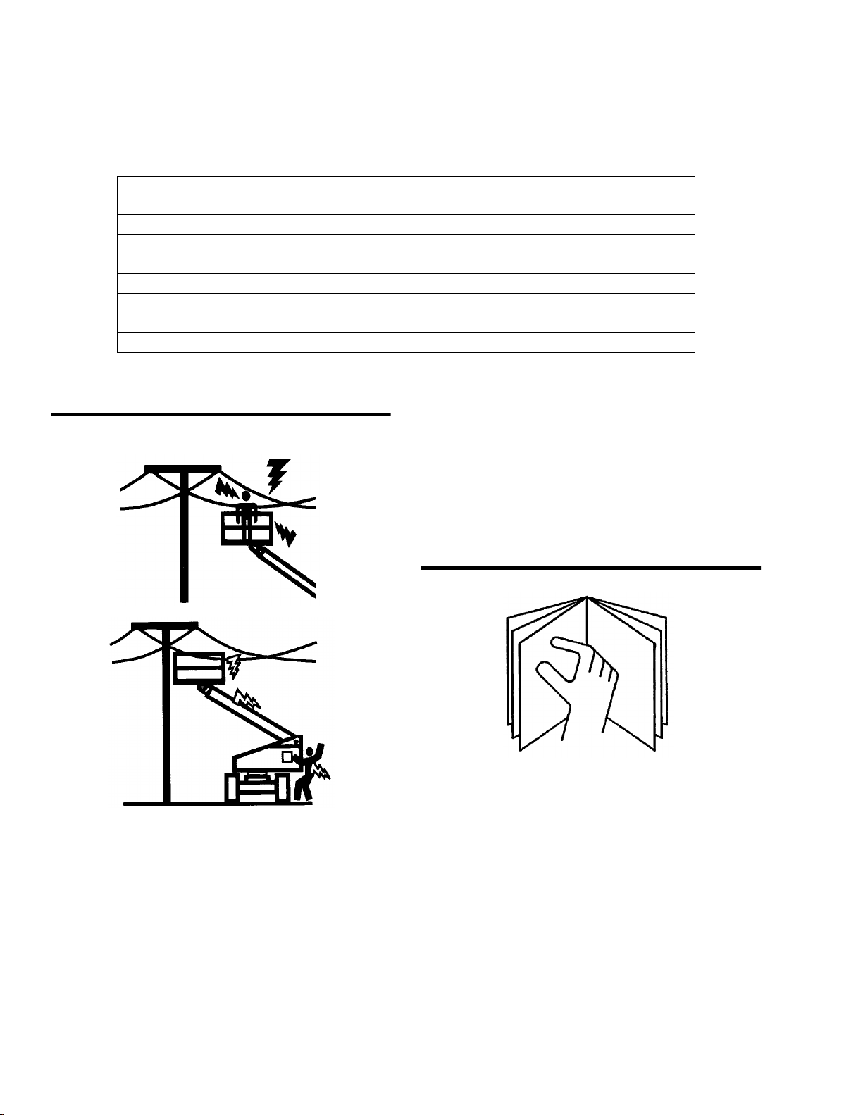
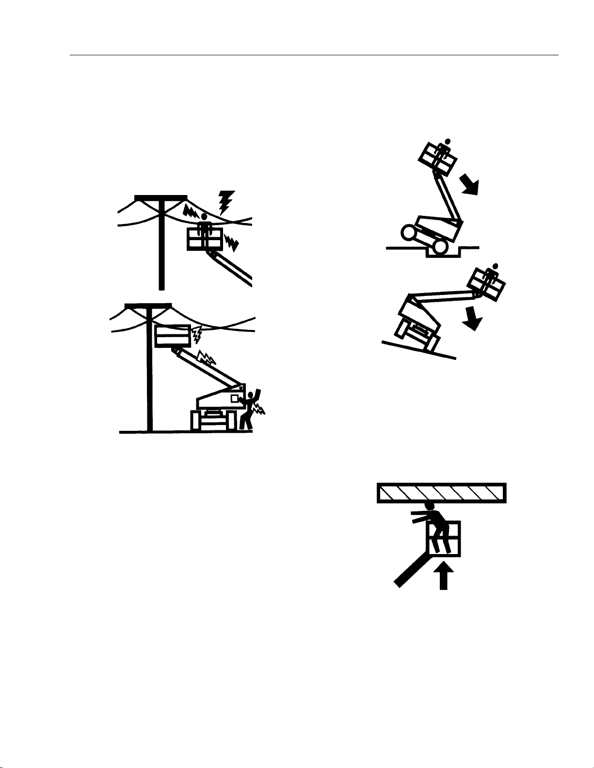
1.3 ELECTROCUTION HAZARD
MINIMUM SAFE APPROACH DISTANCE
in Meters
FROM CONTACT WITH OR PROXIMITY TO AN ELECTRICALLY CHARGED CONDUCTOR.
• MAINTAIN A CLEARANCE OF AT LEAST 3 M (10
FEET) BETWEEN ANY PART OF THE MACHINE OR
ITS LOAD AND ANY ELECTRICAL LINE OR APPARATUS CARRYING UP TO 50,000 VOLTS. 30.5 cm ADDITIONAL CLEARANCE IS REQUIRED FOR EVERY
ADDITIONAL 30,000 VOLTS OR LESS.
1.4 PRE-OPERATIONAL
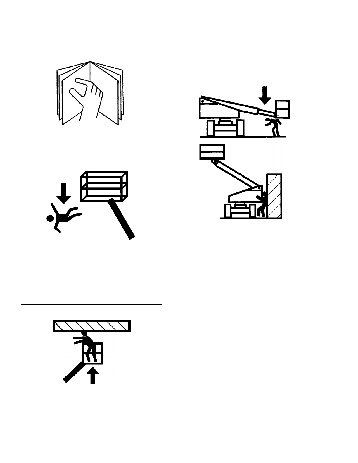
• READ YOUR MANUAL. UNDERSTAND WHAT YOU’VE
READ - THEN BEGIN OPERATIONS.
• MAINTAIN SAFE CLEARANCE FROM ELECTRICAL
LINES AND APPARATUS. ALLOW FOR BOOM SWAY,
ROCK OR SAG AND ELECTRICAL LINE SWAYING.
THE MACHINE DOES NOT PROVIDE PROTECTION
• ALLOW ONLY AUTHORIZED AND QUALIFIED PERSONNEL TO OPERATE MACHINE WHO HAVE DEMONSTRATED THAT THEY UNDERSTAND SAFE AND
PROPER OPERATION AND MAINTENANCE OF THE
UNIT.
1-2 – JLG Lift – 3120868
Page 11
SECTION 1 - SAFETY PRECAUTIONS
• AN OPERATOR MUST NOT ACCEPT OPERATING
RESPONSIBILITIES UNTIL ADEQUATE TRAINING HAS
BEEN GIVEN BY COMPETENT AND AUTHORIZED
PERSONS.
• BEFORE OPERATION, CHECK WORK AREA FOR
OVERHEAD ELECTRIC LINES, MACHINE TRAFFIC
SUCH AS BRIDGE CRANES, HIGHWAY, RAILWAY AND
CONSTRUCTION EQUIPMENT.
• NEVER DISABLE OR MODIFY THE FOOTSWITCH OR
ANY OTHER SAFETY DEVICE. UNAUTHORIZED MODIFICATION OF THE MACHINE IS A SAFETY VIOLATION.
• PRECAUTIONS TO AVOID ALL KNOWN HAZARDS IN
THE WORK AREA MUST BE TAKEN BY THE OPERATOR AND HIS SUPERVISOR BEFORE STARTING THE
WORK.
• DO NOT OPERATE THIS MACHINE UNLESS IT HAS
BEEN SERVICED AND MAINTAINED ACCORDING TO
THE MANUFACTURERS SPECIFICATIONS AND
SCHEDULE.
• ENSURE DAILY INSPECTION AND FUNCTION CHECK
IS PERFORMED PRIOR TO PLACING MACHINE INTO
OPERATION.
• DO NOT OPERATE MACHINE WHEN WIND CONDITIONS EXCEED 12.5 M/S (30MPH).
• NEVER OPERATE BOOM FUNCTIONS (TELE, SWING,
LIFT) WHEN MACHINE IS ON A TRUCK, OTHER VEHICLE, OR ABOVE GROUND STRUCTURE.
• THIS MACHINE CAN BE OPERATED IN NOMINAL
AMBIENT TEMPERATURES OF -20° C TO 40° C (0° F
TO 104° F). CONSULT FACTORY TO OPTIMIZE
OPERATION OUTSIDE THIS RANGE.
• APPROVED HEAD GEAR MUST BE WORN BY ALL
OPERATING AND GROUND PERSONNEL.
3120868 – JLG Lift – 1-3
Page 12
SECTION 1 - SAFETY PRECAUTIONS
.
• READ AND OBEY ALL DANGERS, WARNINGS, CAUTIONS AND OPERATING INSTRUCTIONS ON
MACHINE AND IN THIS MANUAL.
• BE FAMILIAR WITH LOCATION AND OPERATION OF
GROUND STATION CONTROLS.
• ALWAYS POSITION BOOM OVER REAR (DRIVE) AXLE
IN LINE WITH DIRECTION OF TRAVEL. REMEMBER,
IF BOOM IS OVER FRONT (STEER) AXLE, DIRECTION
OF STEER AND DRIVE MOVEMENT WILL BE OPPOSITE FROM NORMAL OPERATION.
• ALWAYS USE THREE POINT CONTACT WHEN
ENTERING OR EXITING THE MACHINE. FACE THE
MACHINE WHEN YOU ENTER OR LEAVE. THREE
POINT CONTACT MEANS THAT TWO HANDS AND
ONE FOOT OR ONE HAND AND TWO FEET ARE IN
CONTACT WITH THE MACHINE AT ALL TIMES DURING MOUNT AND DISMOUNT.
1.5 DRIVING
• WATCH FOR OBSTRUCTIONS AROUND MACHINE
AND OVERHEAD WHEN DRIVING.
• DO NOT USE DRIVE FUNCTION TO POSITION PLATFORM CLOSE TO OBSTACLES. USE BOOM FUNCTION INSTEAD.
• WHEN DRIVING IN HIGH SPEED, SWITCH TO LOW
SPEED BEFORE STOPPING. TRAVEL GRADES IN
LOW DRIVE, HIGH ENGINE ONLY.
• DO NOT USE HIGH SPEED DRIVE WHEN IN
RESTRICTED OR CLOSE QUARTERS, OR WHEN
DRIVING IN REVERSE.
• BE AWARE OF STOPPING DISTANCES WHEN TRAVELING IN HIGH AND LOW SPEEDS.
• ALWAYS POST A LOOKOUT AND SOUND HORN
WHEN DRIVING IN AREAS WHERE VISION IS
OBSTRUCTED.
• KEEP NON-OPERATING PERSONNEL AT LEAST 2 M
(6 FEET) AWAY FROM MACHINE DURING DRIVING
OPERATIONS.
1-4 – JLG Lift – 3120868
Page 13
SECTION 1 - SAFETY PRECAUTIONS
1.6 OPERATION.
• READ YOUR MANUAL. UNDERSTAND WHAT YOU’VE
READ - THEN BEGIN OPERATIONS.
• CHECK TRAVEL PATH FOR PERSONS, DEPRESSIONS, HOLES, BUMPS, DROP-OFFS, OBSTRUCTIONS, DEBRIS, AND COVERINGS WHICH MAY
CONCEAL HOLES AND OTHER HAZARDS.
• TRAVEL IS PERMITTED ON GRADES NO GREATER
THAN THOSE INDICATED ON THE SERIAL NUMBER
PLATE.
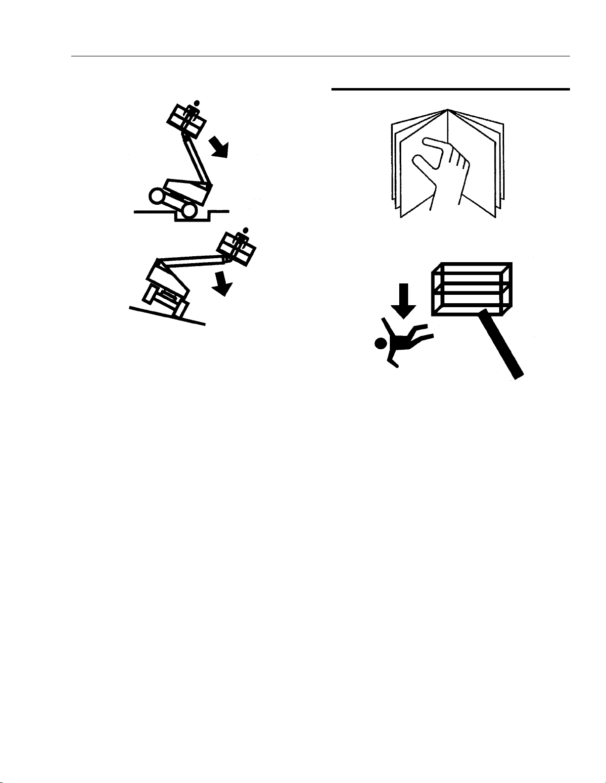
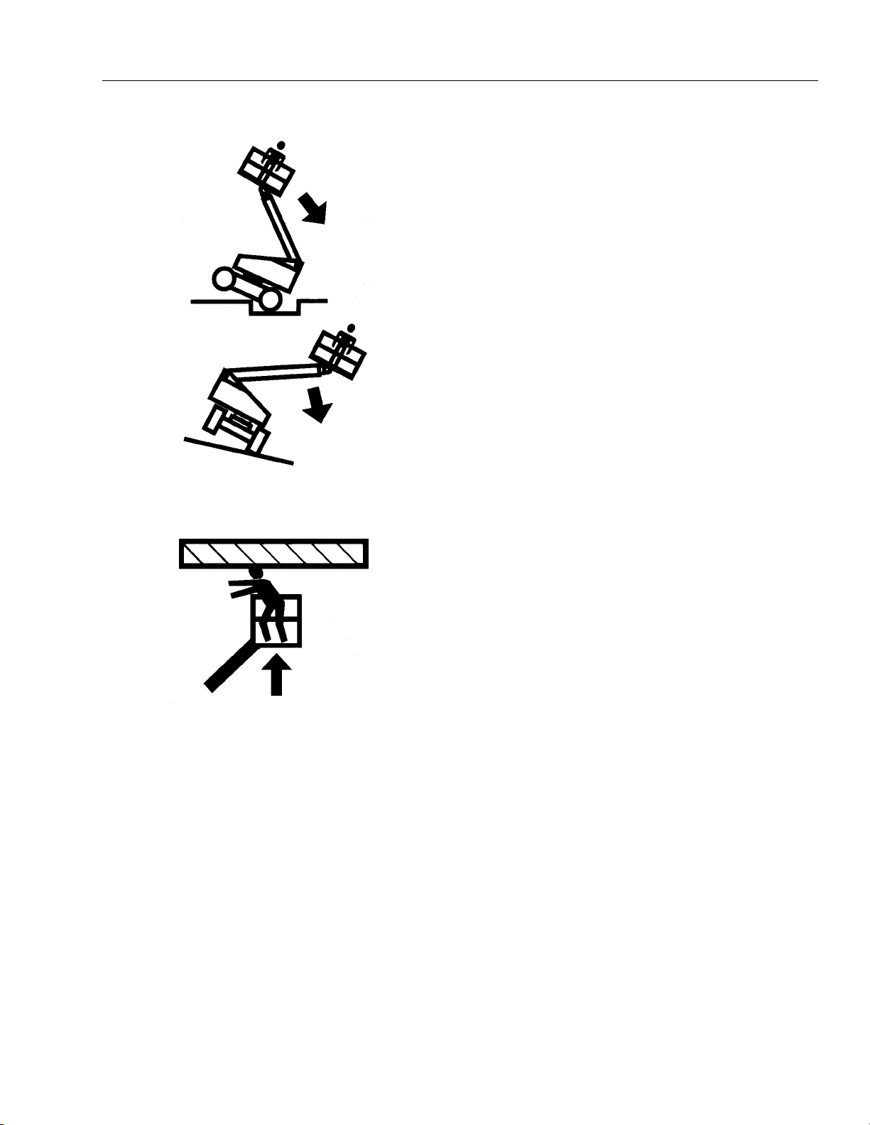
• DO NOT DRIVE ON SIDESLOPES WHICH EXCEED 5°.
• DO NOT TRAVEL ON SOFT OR UNEVEN SURFACES,
AS TIPPING WILL OCCUR.
• DO NOT DRIVE MACHINE NEAR PITS, LOADING
DOCKS OR OTHER DROP-OFFS.
• PRIOR TO ENTERING AND EXITING PLATFORM AT
GROUND LEVEL, FULLY LOWER THE BOOM.
EXTEND BOOM UNTIL END OF FLY BOOM CONTACTS GROUND. WITH BOOM LIFT IN THIS CONFIGURATION, ENTER AND/OR EXIT PLATFORM
THROUGH GATE OPENING.
• JLG RECOMMENDS ALL PERSONS IN THE PLATFORM TO WEAR LANYARDS WITH AN APPROVED
FALL PROTECTION DEVICE. SECURE LANYARD TO
DESIGNATED LANYARD ATTACH POINT ON PLATFORM. KEEP GATE CLOSED AT ALL TIMES.
• TO AVOID FALLING - USE EXTREME CAUTION WHEN
ENTERING OR LEAVING PLATFORM ABOVE
GROUND. ENTER OR EXIT THRU GATE ONLY. PLATFORM FLOOR MUST BE WITHIN 30CM (1 FOOT) OF
ADJACENT - SAFE AND SECURE - STRUCTURE.
ALLOW FOR PLATFORM VERTICAL MOVEMENT AS
WEIGHT IS TRANSFERRED TO OR FROM PLATFORM.
3120868 – JLG Lift – 1-5
Page 14
SECTION 1 - SAFETY PRECAUTIONS
• TRANSFERS BETWEEN A STRUCTURE AND THE
AERIAL PLATFORM EXPOSE OPERATORS TO FALL
HAZARDS. THIS PRACTICE SHOULD BE DISCOURAGED WHEREVER POSSIBLE. WHERE TRANSFER
MUST BE ACCOMPLISHED TO PERFORM THE JOB
TWO LANYARDS WITH AN APPROVED FALL PROTECTION DEVICE WILL BE USED. ONE LANYARD
SHOULD BE ATTACHED TO THE AERIAL PLATFORM.
THE OTHER TO THE STRUCTURE. THE LANYARD
THAT IS ATTACHED TO THE AERIAL PLATFORM
SHOULD NOT BE DISCONNECTED UNTIL SUCH
TIME AS THE TRANSFER TO THE STRUCTURE IS
COMPLETE. OTHERWISE, DO NOT STEP OUTSIDE
OF PLATFORM.
• DO NOT ADD NOTICE BOARDS OR SIMILAR ITEMS
TO THE PLATFORM. ADDITION OF SUCH ITEMS
INCREASES THE EXPOSED WIND AREA OF THE
MACHINE.
• NEVER POSITION LADDERS, STEPS, OR SIMILAR
ITEMS ON UNIT TO PROVIDE ADDITIONAL REACH
FOR ANY PURPOSE.
• WHEN RIDING IN OR WORKING FROM PLATFORM,
BOTH FEET MUST BE FIRMLY POSITIONED ON THE
FLOOR.
• KEEP OIL, MUD AND SLIPPERY SUBSTANCES
CLEANED FROM FOOTWEAR AND PLATFORM
FLOOR.
• NEVER "WALK" THE BOOM TO GAIN ACCESS TO OR
LEAVE PLATFORM.
• NEVER PLACE HANDS OR ARMS IN TOWER BOOM
OR UPRIGHT MECHANISM.
• KEEP ALL NON-OPERATING PERSONNEL AT LEAST
2 METERS (6 FEET) AWAY FROM THE MACHINE AT
ALL TIMES.
• IF PLATFORM OR BOOM IS CAUGHT SO THAT ONE
OR MORE WHEELS ARE OFF THE FLOOR, ALL PERSONNEL MUST BE REMOVED FROM PLATFORM
BEFORE ATTEMPTING TO FREE MACHINE. USE
CRANES, FORKLIFT TRUCKS OR OTHER EQUIPMENT TO REMOVE PERSONNEL AND STABILIZE
MACHINE MOTION, IF NECESSARY.
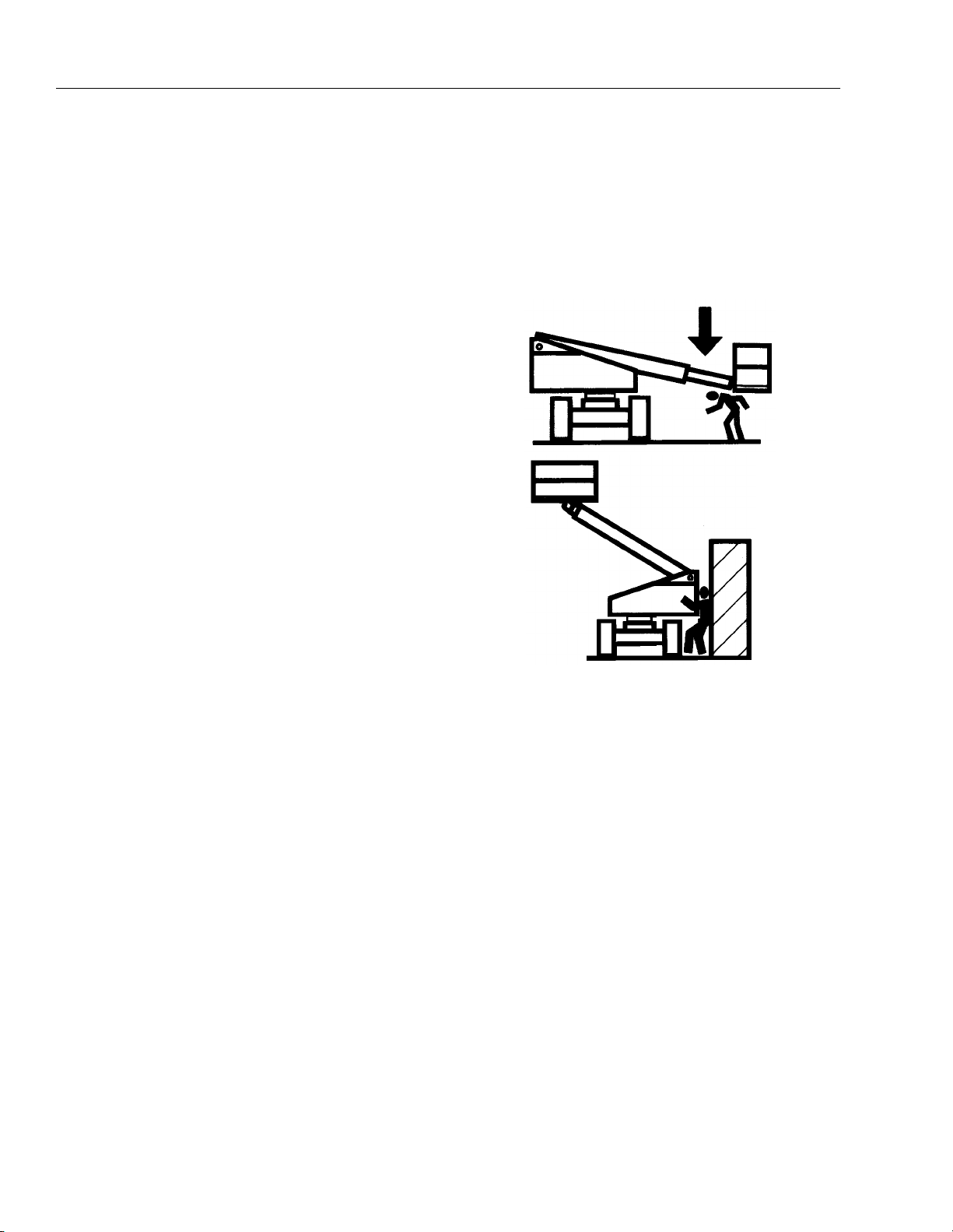
• THE OPERATOR IS RESPONSIBLE TO AVOID OPERATING MACHINE OVER GROUND PERSONNEL AND
TO WARN THEM NOT TO WORK, WALK OR STAND
UNDER A RAISED BOOM OR PLATFORM. POSITION
BARRICADES ON FLOOR IF NECESSARY.
1-6 – JLG Lift – 3120868
Page 15
SECTION 1 - SAFETY PRECAUTIONS
.
• ENSURE MACHINE IS POSITIONED ON A FIRM,
LEVEL AND UNIFORM SUPPORTING SURFACE
BEFORE RAISING OR EXTENDING BOOM.
• CHECK CLEARANCES ABOVE, ON SIDES AND BOTTOM OF PLATFORM WHEN RAISING, LOWERING,
SWINGING, AND TELESCOPING BOOM.
• EXERCISE EXTREME CAUTION AT ALL TIMES TO
PREVENT OBSTACLES FROM STRIKING OR INTER-
FERING WITH OPERATING CONTROLS AND PERSONS IN PLATFORM.
• ENSURE THAT OPERATORS OF OTHER OVERHEAD
AND FLOOR MACHINES ARE AWARE OF THE AERIAL
PLATFORMS PRESENCE. DISCONNECT POWER TO
OVERHEAD CRANES. POSITION BARRICADES ON
FLOOR IF NECESSARY.
• NEVER "SLAM" A CONTROL SWITCH OR LEVER
THROUGH NEUTRAL TO THE OPPOSITE DIRECTION.
ALWAYS RETURN SWITCH TO NEUTRAL AND STOP;
THEN MOVE SWITCH TO THE DESIRED POSITION.
OPERATE LEVERS WITH SLOW, EVEN PRESSURE.
• DO NOT CARRY MATERIALS ON PLATFORM RAILING
UNLESS APPROVED BY JLG INDUSTRIES INC.
• NEVER PUSH OR PULL THE MACHINE OR OTHER
OBJECTS BY TELESCOPING THE BOOM.
• NEVER USE BOOM FOR ANY PURPOSE OTHER
THAN POSITIONING PERSONNEL, THEIR TOOLS
AND EQUIPMENT.
• NEVER EXCEED MANUFACTURERS RATED PLATFORM CAPACITY - REFER TO CAPACITY DECAL ON
MACHINE. DISTRIBUTE LOADS EVENLY ON PLATFORM FLOOR.
• NEVER OPERATE A MALFUNCTIONING MACHINE. IF
A MALFUNCTION OCCURS, SHUT DOWN THE
MACHINE, RED TAG IT, AND NOTIFY PROPER
AUTHORITIES.
• DO NOT REMOVE, MODIFY, OR DISABLE FOOTSWITCH BY BLOCKING OR ANY OTHER MEANS.
• DO NOT ASSIST A STUCK OR DISABLED MACHINE
BY PUSHING OR PULLING EXCEPT BY PULLING AT
CHASSIS TIE-DOWN LUGS.
• NEVER ATTEMPT USING BOOM AS A CRANE.
STRUCTURAL DAMAGE OR TIPPING MAY OCCUR.
• STOW BOOM AND SHUT OFF ALL POWER BEFORE
LEAVING MACHINE.
• NO STUNT DRIVING OR HORSEPLAY IS PERMITTED.
3120868 – JLG Lift – 1-7
Page 16

SECTION 1 - SAFETY PRECAUTIONS
• NEVER ATTEMPT TO FREE A MACHINE STUCK IN
SOFT GROUND OR ASSIST A MACHINE UP A STEEP
HILL OR RAMP BY USING BOOM "LIFT", "TELESCOPE", OR "SWING" FUNCTIONS.
• NEVER ATTACH WIRE, CABLE, OR ANY SIMILAR
ITEMS TO PLATFORM.
• DO NOT PLACE BOOM OR PLATFORM AGAINST ANY
STRUCTURE TO STEADY PLATFORM OR SUPPORT
STRUCTURES.
• DO NOT USE THE LIFT, SWING, OR TELESCOPE
FUNCTIONS FOR THE BOOM, TO MOVE EITHER THE
MACHINE OR OTHER OBJECTS.
• HYDRAULIC CYLINDERS SHOULD NEVER BE LEFT
FULLY EXTENDED OR RETRACTED FOR ANY
LENGTH OF TIME. ALWAYS "BUMP" CONTROL IN
OPPOSITE DIRECTION SLIGHTLY WHEN FUNCTION
BEING USED REACHES END OF TRAVEL. THIS
APPLIES TO MACHINES IN OPERATION OR IN
STOWED MODE.
• DO NOT OPERATE ANY MACHINE ON WHICH DANGER, WARNING, CAUTION OR INSTRUCTION PLACARDS OR DECALS ARE MISSING OR ILLEGIBLE.
• MACHINE MUST ALWAYS BE SHUT DOWN WHEN
REFUELING. NO SMOKING IS MANDATORY. NEVER
REFUEL DURING AN ELECTRICAL STORM. ENSURE
THAT FUEL CAP IS CLOSED AND SECURE AT ALL
OTHER TIMES.
1.7 TOWING AND HAULING
• DO NOT TOW A MACHINE EXCEPT IN AN EMERGENCY. SEE SECTION 6 FOR EMERGENCY TOWING
PROCEDURES.
• LOCK TURNTABLE BEFORE TRAVELING LONG DISTANCES OR BEFORE HAULING MACHINE ON A
TRUCK OR TRAILER.
1-8 – JLG Lift – 3120868
Page 17

SECTION 2 - PREPARATION AND INSPECTION
SECTION 2. PREPARATION AND INSPECTION
2.1 GENERAL
This section provides the necessary information needed
by those personnel that are responsible to place the
machine in operation readiness, and lists checks that are
performed prior to use of the machine. It is important that
the information contained in this section be read and
understood before any attempt is made to operate the
machine. Ensure that all the necessary inspections have
been completed successfully before placing the machine
into service. These procedures will aid in obtaining maximum service life and safe operation.
SINCE THE MACHINE MANUFACTURER HAS NO DIRECT CONTROL OVER THE FIELD INSPECTION AND MAINTENANCE,
SAFETY IS THE RESPONSIBILITY OF THE OWNER/OPERATOR.
2.2 PREPARATION FOR USE
Before a new machine is put into operation it must be
carefully inspected for any evidence of damage resulting
from shipment and inspected periodically thereafter, as
outlined in Delivery and Frequent Inspection (see section
2-3). During initial start-up and run, the unit should be
thoroughly checked for hydraulic leaks. A check of all
components should be made to assure their security.
All preparation necessary to place the machine in operation readiness status is the responsibility of management
personnel. Preparation requires good common sense,
(i.e. telescope works smoothly and brakes operate properly) coupled with a series of visual inspections. The mandatory requirements are given in the Daily Walk Around
Inspection (see section 2-4).
It should be assured that the items appearing in the Delivery and Frequent Inspection and Functional Check are
complied with prior to putting the machine into service.
2.3 DELIVERY AND FREQUENT INSPECTION
NOTE: This machine requires periodic safety and mainte-
nance inspections by an authorized JLG Dealer.
NOTE: An annual inspection shall be performed on the
aerial platform no later than thirteen (13) months
from the date of the prior annual inspection. The
inspection shall be performed by person(s) qualified
as a mechanic on the specific make and model of
the aerial platform.
The following checklist provides a systematic inspection
to assist in detecting defective, damaged, or improperly
installed parts. The checklist denotes the items to be
inspected and conditions to examine.
Frequent inspection shall be performed every 3 months or
150 hours whichever comes first, or more often when
required by environment, severity, and frequency of
usage.
This inspection checklist is also applicable and must be
followed for all machines that have been in storage or for
all machines that will be exposed to harsh or changing climates.
These checks are also to be performed after maintenance
has been performed on the machine.
Chassis
1. Check front tires and wheel assemblies for loose or
worn spindles, components and hardware for security, tires for wear and damage.
2. Check steering assembly for loose or bent tie rod,
cylinder and hydraulic lines for leaks and security,
and hardware for proper installation.
3. If equipped with 4WD, check drive hubs, hydraulic
motors, brakes and hydraulic lines for damage and
leaks.
4. Check rear tires and wheel assemblies for security,
tires for wear and damage.
5. Check drive hubs, hydraulic motors, brakes and
hydraulic lines for damage and leaks.
6. Check oil level in drive hub by removing pipe plug
on side and feeling for oil level. (Contact Service
Personnel for assistance if needed).
NOTE: Torque hubs should be one-half full of lubricant.
7. Check oscillating axle (if equipped) for loose, missing and worn parts, pivot pin and lockout cylinder
pins for security, lockout cylinders and hydraulic
hoses for damage and leaks.
3120868 – JLG Lift – 2-1
Page 18

SECTION 2 - PREPARATION AND INSPECTION
Turnt abl e
1. Check turntable for damage, loose or missing parts,
and security. Check swing drive and brake for damage, loose or missing parts, hydraulic lines and
component housings for evidence of leakage; worm
gear for proper mesh with swing gear.
2. Check swing bearing for damage, wear, lubrication
and loose or missing bearing bolts.
3. Check solenoid valves and hydraulic lines for damage, leakage, security and electrical connections for
tightness and evidence of corrosion.
4. Check ground controls for damage, loose or missing parts, security, electrical connections for evidence of corrosion and tightness and wiring for
insulation damage. Assure that all switches function
properly.
5. Check battery for damage, loose or missing vent
caps, electrical connections for tightness, and evidence of corrosion, hold-down brackets for tightness, and electrolyte for proper water level. Add only
clean distilled water to battery.
6. Check engine tray pivot assembly for damage, loose
or missing parts, and security.
7. Check engine and accessories for damage, loose or
missing parts, leakage and security. Check throttle
solenoid and linkage for damage, electrical connections for tightness, and evidence of corrosion and
wiring for insulation damage.
8. Check fuel lines for damage, leakage and security.
9. Check all access doors for damage, proper operation of latches, props and security.
10. Check fuel tank for damage, leakage and filler cap
for security.
11. Check hydraulic reservoir and hydraulic lines for
damage, leakage and security.
NOTE: JLG recommends replacing the hydraulic filter ele-
ment after the first 50 hours of operation and then
every 300 hours thereafter, unless system indicator
require earlier replacement.
12. Check all pin and shaft retaining hardware for security and wear.
13. Check all electrical cables for defects, damage,
loose or corroded connections.
Boom
1. Check Lower Boom and leveling link for damage,
missing parts and security.
2. Check all pin and shaft retaining hardware for security and wear.
3. Check hydraulic lines and electrical cable for damage, missing parts and security.
4. Check limit switch connections and plunger for corrosion and security.
5. Check Lower Upright, cross pins and hydraulic lines
for damage, wear, lubrication, leakage and security.
6. Check Lower Upright for damage, wear, lubrication
and security.
7. Check hydraulic lines mounted on upright for damage, leakage and security.
8. Check boom pivot bushings for wear.
9. Check boom lift cylinder and hydraulic lines for damage, leakage and security. Check lift cylinder cross
pins for damage, wear and security.
10. Check all pin and shaft retaining hardware for security and wear.
11. Check Upper Upright, cross pins and hydraulic lines
for damage, wear, lubrication, leakage and security.
12. Check Upper Upright for damage, wear, lubrication
and security.
13. Check hydraulic lines mounted on upright for damage, leakage and security.
14. Check Upper Boom Lift Cylinder and cross pins and
hydraulic lines for damage, wear, lubrication, leakage and security.
2-2 – JLG Lift – 3120868
Page 19
SECTION 2 - PREPARATION AND INSPECTION
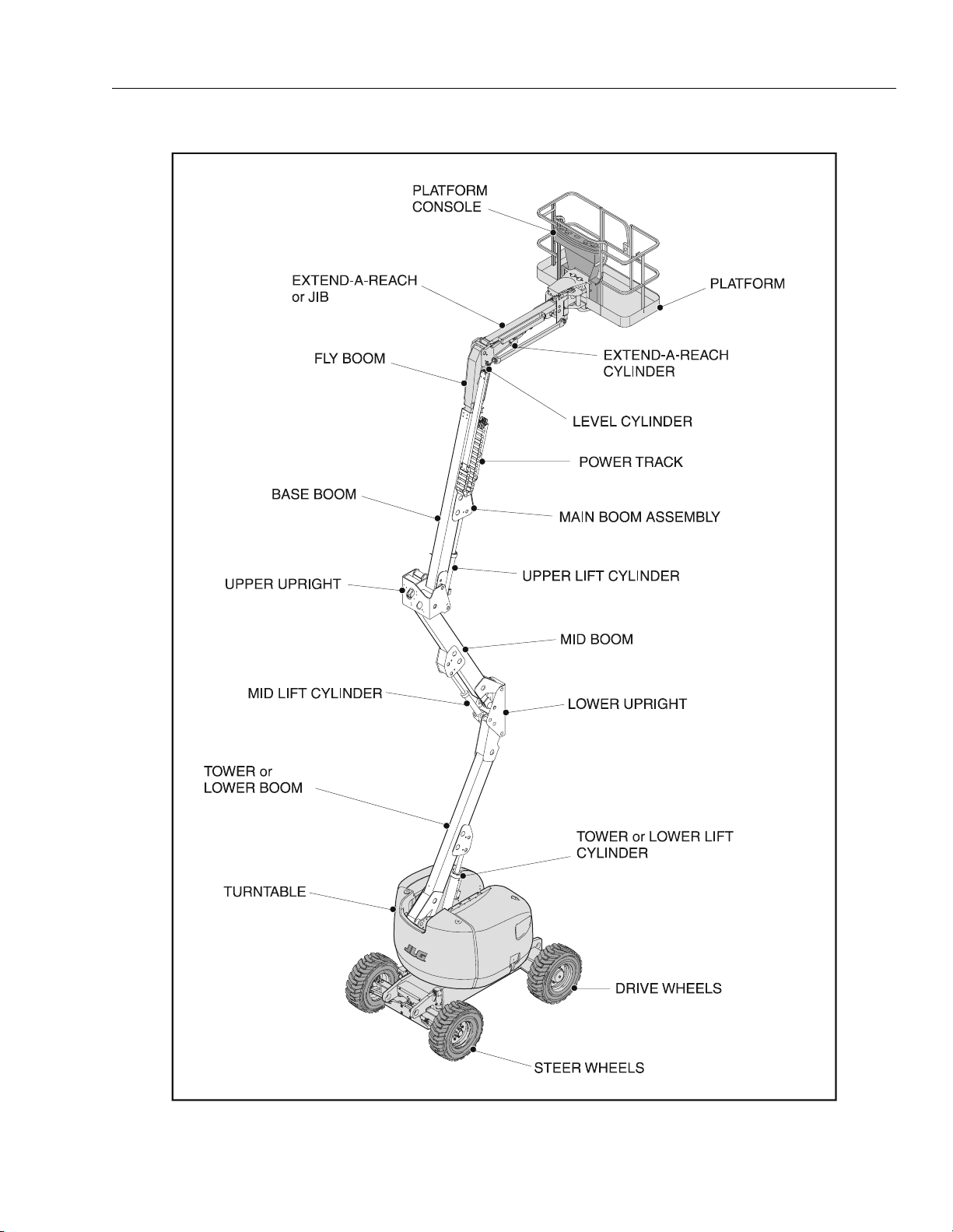
Figure 2-1. Machine Nomenclature
3120868 – JLG Lift – 2-3
Page 20

SECTION 2 - PREPARATION AND INSPECTION
15. Check Upper Boom pivot pin for damage, wear,
lubrication and security.
16. Check Upper Boom for damage, missing parts and
security.
17. Check Upper Boom wear pads for damage, missing
parts and security.
18. Check Upper Boom telescope cylinder, cross pins
and hydraulic lines for damage, wear, lubrication,
leakage and security.
19. Check Platform Leveling Cylinder, cross pins and
hydraulic lines for damage, wear, lubrication, leakage and security.
Platform
1. Check platform and control console for damage,
loose or missing parts, and security.
2. Check control switches and levers for damage,
loose or missing parts and security. Assure that
levers function properly.
3. Check control switches, levers and electrical connections for tightness and evidence of corrosion,
and wiring for defects and chafing damage. Assure
that switches function properly.
4. Check access gate hinges, stop, and latch for
proper operation, damage and security.
5. Check platform rotator mechanism for proper operation, damage, security. Check hydraulic lines for
leakage, damage and security.
NOTE: Check all DANGER, WARNING, CAUTION and
INSTRUCTION placards for legibility and security on
the entire machine.
Tor q ue R e q u i r e m e n t s
The Torque Chart (Figure 2-6.) consists of standard torque
values based on bolt diameter and grade, also specifying
dry and wet torque values in accordance with recommended shop practices. This chart is provided as an aid
to the operator in the event he/she notices a condition that
requires prompt attention during the walk-around inspection or during operation, until the proper service personnel
can be notified. The Service and Maintenance manual
provides specific torque values and periodic maintenance
procedures with a listing of individual components. Utilizing this Torque Chart in conjunction with the preventive
maintenance section in the Service and Maintenance
manual will enhance safety, reliability, and performance of
the machine.
2-4 – JLG Lift – 3120868
Page 21

SECTION 2 - PREPARATION AND INSPECTION
2.4 DAILY WALK-AROUND INSPECTION
It is the operators responsibility to inspect the machine
before the start of each workday. It is recommended that
each operator inspect the machine before operation, even
if the machine has already been put into service under
another operator. This Daily Walk-Around Inspection is the
preferred method of inspection.
These checks are also to be performed after maintenance
has been performed on the machine.
In addition to the Daily Walk-Around Inspection, be sure to
include the following as part of the daily inspection:
1. Overall cleanliness.
Check all standing surfaces for oil, fuel and hydraulic oil spillage and foreign objects. Ensure overall
cleanliness.
2. Placards.
Keep all information and operating placards clean
and unobstructed. Cover when spray painting or
shot blasting to protect legibility.
3. Operator’s and Safety Manual.
Ensure a copy of this manual and the ANSI A92.51992 Responsibilities, are enclosed in the manual
storage box.
4. Machine Log.
Ensure a machine operating record or log is kept,
check to see that it is current and that no entries
have been left uncleared, leaving machine in an
unsafe condition for operation.
5. Start each day with a full fuel tank.
TO AVOID INJURY, DO NOT OPERATE A MACHINE UNTIL ALL
MALFUNCTIONS HAVE BEEN CORRECTED. USE OF A MALFUNCTIONING MACHINE IS A SAFETY VIOLATION.
TO AVOID POSSIBLE INJURY, BE SURE MACHINE POWER IS
"OFF" DURING WALK-AROUND INSPECTION.
NOTE: Check boom limit switches on upright for proper
operation and security, both visually and manually.
The lower switch cuts out drive speed when the
lower boom is above horizontal. The upper switch
cuts out drive speed when the upper boom is above
horizontal. Only creep drive speed will continue to
function.
6. Check platform footswitch for proper operation.
Switch must be released to start engine and
depressed to operate machine.
7. Check that drive brakes hold when machine is
driven up a grade not greater than specified on the
serial number placard and stopped.
NOTE: On new machines, those recently overhauled, or
after changing hydraulic oil, operate all systems a
minimum of two complete cycles and recheck oil
level in reservoir.
8. Assure that all items requiring lubrication are serviced. Refer to Figure 2-5., Lubrication Diagram for
specific requirements.
3120868 – JLG Lift – 2-5
Page 22

SECTION 2 - PREPARATION AND INSPECTION
Figure 2-2. Daily Walk-Around Inspection - Sheet 1 of 3
2-6 – JLG Lift – 3120868
Page 23

SECTION 2 - PREPARATION AND INSPECTION
GENERAL
Begin the "Walk-Around Inspection" at Item 1, as noted on
the diagram. Continue to the right (counterclockwise
viewed from top) checking each item in sequence for the
conditions listed in the Walk-Around Inspection Checklist.
TO AVOID INJURY, DO NOT OPERATE A MACHINE UNTIL ALL
MALFUNCTIONS HAVE BEEN CORRECTED. USE OF A MALFUNCTIONING MACHINE IS A SAFETY VIOLATION. TO AVOID POSSIBLE INJURY, BE SURE MACHINE POWER IS OFF DURING WALKAROUND INSPECTION.
NOTE: Do not overlook visual inspection of chassis under-
side. Checking this area often results in discovery of
conditions which could cause extensive machine
damage.
1. Platform Assembly - No loose or missing parts, no
visible damage. Lockbolts in place. Footswitch in
good working order, not modified, disabled or
blocked.
2. Platform Control Console - Switches and levers
return to neutral and are properly secured, no loose
or missing parts, no visible damage, decals/placards
secure and legible, control marking legible.
3. Slave Cylinder - No visible damage; pivot pins
secure hydraulic hoses undamaged, not leaking.
4. Boom Sections/Uprights/Lift Cylinders and Master
Cylinder - No visible damage; pivot pins secure;
hydraulic hoses undamaged, not leaking. Uprights
in vertical position.
5. Horizontal Limit Switches - Switches operable; no
visible damage.
6. Drive Motor, Brake, and Hub - No visible damage; no
evidence of leakage.
7. Wheel/Tire Assembly, Right Rear - Properly secured,
no loose or missing lug nuts, no visible damage.
8. Hydraulic Filter - Housing secure no visible damage;
no evidence of leakage.
9. Hood, Right Side - Properly secured; no loose or
missing parts.
10. Control Valve - No loose or missing parts; evidence
of leakage; unsupported wires or hoses; damaged
or broken wires.
11. Fuel Supply - Filler cap secure, no visible damage to
the tank or evidence of leaks.
12. Ground Controls - Switches operable, no visible
damage, decals secure and legible.
13. Hydraulic Oil Supply - Recommended oil level sight
gauge. (Check level with cold oil, systems shut
down, machine in stowed position) Cap in place and
secure.
14. Wheel/Tire Assembly, Right Front - Properly secured,
no loose or missing lug nuts, no visible damage.
15. Oscillating Axle - No loose or missing hardware; no
visible damage.
16. Steer Cylinder - Properly secured; no visible damage
or signs of leakage; evidence of proper lubrication.
17. Tie Rod Ends and Steering Spindles - No loose or
missing parts; no visible damage.
18. Wheel/Tire Assembly, Left Front - Properly secured,
no loose or missing lug nuts, no visible damage.
19. Battery - Proper electrolyte levels; cables tight, no
visible damage or corrosion.
20. Engine Air Filter - No loose or missing parts; no visible damage; element clean.
21. Hood, Right Side - Properly secured; no loose or
missing parts.
22. Engine Oil Supply - Full mark on dipstick; filler cap
secure.
Figure 2-3. Daily Walk-Around Inspection - Sheet 2 of 3
3120868 – JLG Lift – 2-7
Page 24

SECTION 2 - PREPARATION AND INSPECTION
23. Turntable Bearing - No loose or missing hardware;
no visible; evidence of proper lubrication; no evidence of loose bolts or looseness between bearing
or structure.
24. Swing Motor and Worm Gear - No loose or missing
hardware; no visible damage; evidence of proper
lubrication.
25. Muffler and Exhaust System - Properly secured, no
evidence of leakage.
26. Auxiliary Power Pump - No loose or missing parts, no
evidence of leakage, no damaged wires.
Figure 2-4. Daily Walk-Around Inspection - Sheet 3 of 3
27. Hydraulic Pump - No loose or missing parts, no evidence of leakage.
28. Wheel/Tire Assembly, Left Rear - Properly secured,
no loose or missing lug nuts, no visible damage.
29. Rotator Cylinders - No visible damage; cylinder pins
secure; hydraulic hoses undamaged and not leaking.
30. Platform Gate - Latch, stop, and hinges or drop bar
in working condition and properly secured; no loose
or missing parts.
2-8 – JLG Lift – 3120868
Page 25

SECTION 2 - PREPARATION AND INSPECTION
2.5 DAILY FUNCTIONAL CHECK
A functional check of all systems must be performed,
once the walk-around inspection is complete, in an area
free of overhead and ground level obstructions. First,
using the ground controls, check all functions controlled
by the ground controls. Next, using the platform controls,
check all functions controlled by the platform controls.
TO AVOID SERIOUS INJURY, DO NOT OPERATE MACHINE IF ANY
CONTROL LEVERS OR TOGGLE SWITCHES CONTROLLING
PLATFORM MOVEMENTS DO NOT RETURN TO THE OFF OR NEUTRAL POSITION WHEN RELEASED.
TO AVOID A COLLISION AND INJURY IF PLATFORM DOES NOT
STOP WHEN A CONTROL SWITCH OR LEVER IS RELEASED,
REMOVE FOOT FROM FOOTSWITCH OR USE EMERGENCY STOP
TO STOP THE MACHINE.
NOTE: When the boom is raised above horizontal, high
drive speed is cut out.
1. Check boom horizontal limit switches to see that
they are operable and not damaged. Raise and
lower Lower Boom. Check for smooth operation.
Check Boom Upright tilting for proper synchronization. If the upright is tilted or the boom will not fully
lower, refer to the Boom Synchronizing Procedure in
Section 3.
NOTE: Perform checks from ground controls first, then from
platform controls.
2. Raise, extend, retract and lower Upper Boom.
Check for smooth operation.
3. Telescope boom IN and OUT several cycles at various degrees of elevation lengths. Check for smooth
telescope operation.
4. Swing turntable to LEFT and RIGHT a minimum of
45 degrees. Check for smooth motion.
5. With the aid of an assistant to monitor the CHASSIS
OUT OF LEVEL indicator light on the platform console, manually activate the indicator light by compressing one of the three tilt indicator mounting
springs. If the light does not illuminate, shut down
machine and contact a qualified service technician
before continuing operation.
6. Check that platform self-leveling system functions
properly during raising and lowering of boom.
7. Check rotator for smooth operation and assure platform will rotate 75 degrees in both directions from
centerline of boom.
8. Drive forward and reverse; check for proper operation.
9. Steer left and right; check for proper operation.
10. Footswitch.
FOOTSWITCH MUST BE ADJUSTED SO THAT FUNCTIONS WILL
OPERATE WHEN PEDAL IS APPROXIMATELY AT ITS CENTER OF
TRAVEL. IF SWITCH OPERATES WITHIN LAST 1/4" OF TRAVEL,
TOP OR BOTTOM, IT SHOULD BE ADJUSTED.
a. Activate hydraulic system, by depressing foot-
switch. Operate Telescope and hold control.
Remove foot from footswitch, motion should
stop. If it does not, shut down machine and contact a certified JLG service technician.
b. With footswitch depressed, operate Lift and hold
control. Remove foot from footswitch, motion
should stop. If it does not, shut down machine
and contact a certified JLG service technician.
c. With engine power shut down, depress the foot-
switch. Attempt to start engine. Engine should
not attempt to start when footswitch is
depressed. If starter engages or engine turns
over, shut down machine and contact a certified
JLG service technician.
11. Auxiliary Power.
Operate each function control switch (e.g. Tele, Lift,
and Swing) to assure that they function in both
directions using auxiliary power instead of engine
power.
12. Ground Controls.
Place Ground/Platform Select switch to Ground.
Start engine. Platform controls should not operate.
3120868 – JLG Lift – 2-9
Page 26

SECTION 2 - PREPARATION AND INSPECTION
2.6 BATTERY MAINTENANCE
TO AVOID INJURY FROM AN EXPLOSION, DO NOT SMOKE OR
ALLOW SPARKS OR A FLAME NEAR BATTERY DURING SERVICING.
ALWAYS WEAR EYE PROTECTION WHEN SERVICING BATTERIES.
1. The battery is maintenance free except for occasional battery terminal cleaning, as noted in the following.
2. Remove battery cables from each battery post one
at a time, negative first. Clean cables with acid neutralizing solution (e.g. baking soda and water or
ammonia) and wire brush. Replace cables and/or
cable clamp bolts as required.
3. Clean battery post with wire brush then re-connect
cable to post. Coat non-contact surfaces with mineral grease or petroleum jelly (Vaseline).
4. When all cables and terminal posts have been
cleaned, ensure all cables are properly positioned
and are not pinched. Close battery compartment
cover.
2-10 – JLG Lift – 3120868
Page 27

SECTION 2 - PREPARATION AND INSPECTION
Figure 2-5. Lubrication Diagram
3120868 – JLG Lift – 2-11
Page 28

SECTION 2 - PREPARATION AND INSPECTION
Table 2-1. Lubrication Chart
Components
Lubrication
Swing Bearing - Internal
1
Ball Bearing
Swing Bearing - Teeth
2a
End Bearings - Worm
2b
Gear*
Wheel Bearings (2WD
3
Only)
Wheel Drive Hub
4
Hydraulic Return Filter
5
Hydraulic Charge Filter
6
Hydraulic Oil
7
Suction Strainer s (In Tank)
8
Steer Cylinder
9
Oscillation Cylinders
10
Number/Type
Lube Points
Capacity Lube
2 Grease Fitt ing A/R MPG X
Spray On A/R OGL X More frequent lubrication intervals may be
2 A/R MPG X Remove grease fittings and install plugs after
Repack A/R MPG X
Level/Fill Pl ug 0.5 lite rs (1/2 full) EPGL X Change after fi rst 150 hours the n every 1200
N/A N/A N/A X Change afte r first 50 hours and e very 300
N/A N/A N/A X Change afte r first 50 hours and e very 300
F il l C a p 11 6 l i te r s Ta n k
124 liters System
2 N/A N/A X Remove and clean at time of hydraulic oil
4A/RMPGX
2A/RMPGX
Interval Hours
3
Months
150 hrs
HO X Check level daily.
6
Months
300 hrs
1 Year
600 hrs
2 Years
1200 hrs
required.
greasing.
hours of op eration.
hours thereafter or as indicated by condition
indicator.
hours thereafter or as indicated by condition
indicator.
Change eve ry 1200 hours.
change.
Comments
Engines
Oil Change w/Filter - Ford
11
Oil Change w/Filter - Deutz
12
Oil Change w/Filter - Isuzu
13
Fuel Filter - Ford
14
Fill Cap/Spin-on
Element
Fill Cap/Spin-on
Element
Fill Cap/Spin-on
Element
Replaceable
5 Quarts (4.7 L) EO X Check le vel daily; chan ge every 150 hour s.
Adjust final oil level by mark on dipstick.
6 liters crankcase
**4. 5 liters cooler
5.6 liters crankcase
6.1 liters w /cooler
EO X Check level dail y; change every 600 hours.
Adjust final oil level by mark on dipstick.
EO X Check level dail y; change every 150 hours.
Adjust final oil level by mark on dipstick.
N/A N/A X
Element
15
Fuel Filter - Deutz
Replaceable
N/A N/A X
Element
Fuel Filter - Isuzu
16
Replaceable
Element
N/A N/A X
Updated 11-2-99
2-12 – JLG Lift – 3120868
Page 29

SECTION 2 - PREPARATION AND INSPECTION
Table 2-1. Lubrication Chart
Interval Hours
Components
Air Filter - Ford
17
Air Filter - Deut z
18
Air Filter - Isuzu
19
NOTES: KEY TO LUBRICANTS
Lubrication intervals are based on machine operation under normal conditions. For machines used in multi shift operations and/or exposed to hostile environments or conditions, lubrication frequencies must be increased accordingly.
* If necessary install grease fittings into worm gear housing and grease bearings.
DO NOT OVERGREASE BEARINGS. OVERGREASING BEARINGS WILL RESULT IN
BLOWING OUTER SEAL IN HOUSING.
**When changing oil in the Deutz oil cooled engine, drain both the crankcase and the cooler. When refilling it is acceptable to overfill crankcase (10.5 L),
capacity of both crankcase and cooler combined). Start engine, allow the engine to run until the thermostat opens (approximately 105 degrees C) cooler will
fill up within minutes; shut down and wait for approximately two minutes. Check oil level, fill oil to max marking on dipstick.
Number/Type
Lube Points
Replaceable
Element
Replaceable
Element
Replaceable
Element
Capacity Lube
N/A N/A X Or as indicated by condition indicator
N/A N/A X Or as indicated by condition indicator
N/A N/A X Or as indicated by condition indicator
3
Months
150 hrs
6
Months
300 hrs
1 Year
600 hrs
2 Years
1200 hrs
EO
EPGL
HO
MPG
OGL
Engine Oil
Extreme Pres sure Gear Lube
Hydraulic Fluid (Mobil DTE-11M)
Multi-Pu rpose Grease
Open Gear Lubricant - Mobiltac 375 or
equivalent
Comments
Updated 11-2-99
3120868 – JLG Lift – 2-13
Page 30

SECTION 2 - PREPARATION AND INSPECTION
95
68
61
37
34
19
18
3493
2631
2377
1651
1442
41
41
21
18
54
34
30
6
5
4
12
14
25
27
68
48
4822
3983
75
109
85
61
75
48
102
5384
122
95
81
UNPLATED
CAP SCREWS
WITH LOC-WEL PATCH
UNBRAKO 1960 SERIES
SOCKET HEAD CAP SCREW
TORQUE
NM
TORQUE
(as received)
(KG)
CLAMP LOAD
)
M
N
(LOCTITE
242 OR 271
M
262)
N
(LOCTITE
M
N
(LUB.)
4
2
2
1
1
156
149
7253
6437
163
183
146
130
109
122
224
210
9208
8256
224
209
188
176
149
258
298
285
11612
10251
359
326
277
244
244
231
542
495
16919
15150
631
570
456
408
434
380
861
793
23088
20956
983
895
724
658
678
624
1241
1173
30074
27488
1492
1342
931
1079
922
1003
1871
1681
38828
34610
2136
1898
1566
1396
1302
1464
2549
2373
48671
43954
2983
2712
2183
1970
2034
1844
3308
3145
59648
52391
4068
3559
2586
2935
2766
2413
4433
4122
71669
63731
4712
5322
3856
3430
3200
3607
SAE GRADE 8
SAE GRADE 5
VALUES FOR ZINC PLATED BOLTS ONLY
(DRYOR
SAE GRADE 8 BOLTS & GRADE 8 NUTS
CLAMP
(LOCTITE
(LOCTITE
TORQUE
(DRYOR
SAE GRADE 5 BOLTS & GRADE 2 NUTS
CLAMP
AREA
STRESS
THREAD
DIA.
BOLT
M
N
LOC. 263)
(KG)
LOAD
)
M
N
242 OR 271
M
262)
N
M
N
(LUB.)
M
N
LOC. 263)
(KG)
LOAD
(SQ. CM)
(CM)
2
2
272
245
1
1
1
1
172
191
0.0168
0.0153
0.2845
3
3
417
372
2
2
2
2
263
277
0.0258
0.0232
0.3505
5
5
599
572
3
3
4
4
408
426
0.0374
0.0356
0.4166
8
7
817
717
4
4
6
5
508
583
0.0445
0.0508
0.4826
19
16
1488
1297
12
16
9
10
11
14
916
1052
0.0808
0.0925
0.6350
34
34
2821
2141
29
26
23
22
19
18
26
23
1515
1678
0.1473
0.1331
0.7938
61
68
3583
3175
54
48
43
38
34
31
48
41
2241
2540
0.2230
0.1969
0.9525
95
109
4332
4854
81
75
61
68
68
48
68
75
3425
3085
0.3015
0.2700
1.1112
163
149
6532
5783
115
136
92
108
75
88
102
122
4105
4854
0.4061
0.3604
1.2700
231
204
8278
7539
163
183
133
148
109
122
149
163
5874
5262
0.5156
0.4623
1.4288
326
298
9231
10433
224
258
207
183
149
176
204
231
7394
6532
0.6502
0.5740
1.5875
570
515
15241
13653
387
448
363
325
271
298
407
353
9662
10796
0.9474
0.8484
1.9050
895
814
20775
18870
644
705
576
523
434
475
637
583
14697
13336
1.2929
1.1735
2.2225
1220
1356
27080
23360
915
997
785
858
651
719
868
949
19142
17509
1.6840
1.5392
2.5400
1953
1736
34927
31162
1139
1254
968
1087
814
895
1085
1193
21546
19187
2.1742
1.9380
2.8575
2712
2468
43818
38554
1593
1762
1516
1368
1139
1247
1681
1519
27035
24404
2.7254
2.4613
3.1750
3688
3227
53570
47174
2068
2373
2042
1792
1492
1708
1980
2278
29076
33113
2.9337
3.3401
3.4925
4827
4284
57380
142200
3118
2746
2676
2379
2224
1980
2983
2630
39781
35381
4.0132
3.5687
3.8100
Figure 2-6. Torque Chart
9
8
7
7
6
THD
SIZE
40
48
40
36
32
32
24
6
4
8
10
32
20
1/4
28
18
5/16
24
16
3/8
24
14
7/16
20
13
1/2
20
12
9/16
18
11
5/8
18
10
3/4
16
7/8
14
12
12
1
1-1/8
1-1/4
12
12
1-1/2
6
1-1/2
12
Note: These torque values do not apply to cadium plated fasteners.
2-14 – JLG Lift – 3120868
Page 31

SECTION 3 - USER RESPONSIBILITIES AND MACHINE CONTROL
SECTION 3. USER RESPONSIBILITIES AND MACHINE CONTROL
3.1 GENERAL
SINCE THE MANUFACTURER HAS NO DIRECT CONTROL OVER
MACHINE APPLICATION AND OPERATION, CONFORMANCE WITH
GOOD SAFETY PRACTICES IN THESE AREAS IS THE RESPONSIBILITY OF THE USER AND HIS/HER OPERATING PERSONNEL.
This section provides the necessary information needed
to understand control functions. Included in this section
are the operating characteristics and limitations, and functions and purposes of controls and indicators. It is important that the user and/or operator read and understand the
proper procedures before operating the machine. These
procedures will aid in obtaining optimum lift service and
safe operation.
3.2 PERSONNEL TRAINING
The aerial platform is a personnel handling device; therefore it is essential that it be operated and maintained only
by authorized and qualified personnel who have demonstrated that they understand the proper use and maintenance of the machine. It is important that all personnel
who are assigned to and responsible for the operation
and maintenance of the machine undergo a thorough
training program and check out period in order to become
familiar with the characteristics prior to operating the
machine.
Persons under the influence of drugs or alcohol or who
are subject to seizures, dizziness or loss of physical control must not be permitted to operate the machine.
Operator Training
Operator training must include instruction in the following
areas:
1. Use and limitations of the platform controls, ground
controls, emergency controls and safety systems.
2. Knowledge and understanding of this manual and of
the control markings, instructions and warnings on
the machine itself.
3. Knowledge and understanding of all safety work
rules of the employer and of Federal, State and local
statutes, including training in the recognition and
avoidance of potential hazards in the work place;
with particular attention to the work to be performed.
4. Proper use of all required personnel safety equipment, in particular the wearing of a safety harness or
other approved fall protection devices with a lanyard
attached to the platform at all times.
5. Sufficient knowledge of the mechanical operation of
the machine to recognize a malfunction or potential
malfunction.
6. The safest means to operate the machine where
overhead obstructions, other moving equipment,
and obstacles, depressions, holes, drop-offs, etc. on
the supporting surface exist.
7. Means to avoid the hazards of unprotected electrical
conductors.
8. Any other requirements of a specific job or machine
application.
Tra ini ng Su pe rv is io n
Training must be done under the supervision of a qualified
person in an open area free of obstructions until the
trainee has developed the ability to safely control a
machine in congested work locations.
Operator Responsibility
The operator must be instructed that he/she has the
responsibility and authority to shut down the machine in
case of a malfunction or other unsafe condition of either
the machine or the job site and to request further information from his/her supervisor or an authorized JLG Distributor before proceeding.
NOTE: Manufacturer or distributor will provide qualified per-
sons for training assistance with first unit(s) delivered
and thereafter as requested by the user or his/her
personnel.
3120868 – JLG Lift – 3-1
Page 32

SECTION 3 - USER RESPONSIBILITIES AND MACHINE CONTROL
3.3 OPERATING CHARACTERISTICS AND LIMITATIONS
General
A thorough knowledge of the operating characteristics
and limitations of the machine is always the first requirement for any user, regardless of the user’s experience with
similar types of equipment.
Placards
Important points to remember during operation are provided at the control stations by DANGER, WARNING,
CAUTION, IMPORTANT and INSTRUCTION placards. This
information is placed at various locations for the express
purpose of alerting personnel of potential hazards constituted by the operating characteristics and load limitations
of the machine. See FOREWORD for definitions of the
above placards.
Capacities
Raising boom above horizontal and/or extension of boom
beyond retracted position with or without any load in platform, is based on the following criteria:
1. Machine is positioned on a smooth, firm and level
surface.
2. Load is within manufacturer’s rated design capacity.
3. All machine systems are functioning properly.
4. Proper tire pressure exists in the tires.
5. Machine is as originally equipped from JLG.
Stability
This machine as originally manufactured by JLG Industries Inc., when operated within its rated capacity on a
smooth, firm and level supporting surface, and in accordance with the instructions provided on the machine and
this manual, provides a stable machine for all platform
positions.
Machine stability is based on two positions which are
called FORWARD STABILITY and BACKWARD STABILITY.
The machines position of least forward stability is shown
in Figure 3-1., and its position of least backward stability is
shown in Figure 3-2.
TO AVOID FORWARD OR BACKWARD UPSET, DO NOT OVERLOAD MACHINE OR OPERATE ON AN OUT-OF-LEVEL SURFACE.
Boom Synchronizing Procedure
If the lower boom does not fully lower, use the following
procedure.
1. Remove all personnel from the platform.
2. Pull out the red EMS (emergency stop) knob located
on the ground control station.
3. Turn the platfrom/ground select switch to the ground
control position.
4. If applicable, start the engine.
5. Pull and hold out the red re-level knob on the synchronizing valve located beside the main control
valve.
6. From the ground controls, activate the lift control
switch, and raise the lower boom approximately 2 m
(6 feet).
7. After raising the lower boom, release the red knob.
8. Activate the lift control switch and fully lower the
boom and continue to hold down the switch for an
additional 5 seconds.
9. Repeat steps 5 thru 8 if necessary.
3-2 – JLG Lift – 3120868
Page 33

SECTION 3 - USER RESPONSIBILITIES AND MACHINE CONTROL
Figure 3-1. Position of Least Forward Stability
3120868 – JLG Lift – 3-3
Page 34

SECTION 3 - USER RESPONSIBILITIES AND MACHINE CONTROL
Figure 3-2. Position of Least Backward Stability
3-4 – JLG Lift – 3120868
Page 35

SECTION 3 - USER RESPONSIBILITIES AND MACHINE CONTROL
3.4 CONTROLS AND INDICATORS
NOTE: This machines is equipped with control panels that
use symbols to indicate control functions. Refer to
Figure 3-7. and Figure 3-8. for the symbols on the
decal located on the control box guard in front of the
control box or by the ground controls for these control panel symbols and the corresponding functions.
Ground Controls
PERFORM PRE-OPERATIONAL CHECKS AND
INSPECTIONS FROM THE GROUND CONTROL STATION. WHEN PERSONNEL ARE IN THE PLATFORM,
OPERATION OF THE BOOM WILL ONLY BE PERFORMED WITH THE PERMISSION OF THE PLATFORM
OCCUPANT(S).
NOTE: When Power/Emergency Stop switch is in the on
position and engine is not running, an alarm will
sound, indicating Ignition is on.
WHEN THE MACHINE IS SHUT DOWN THE MASTER/EMERGENCY
STOP SWITCH MUST BE POSITIONED TO THE OFF POSITION TO
PREVENT DRAINING THE BATTERY.
1. Power/Emergency Stop Switch.
Pull out on-off Power/Emergency Stop Switch to turn
on engine ignition and power to the electrical system. Push in to shut off engine and remove power
from the controls. The Ground Control Emergency
Stop Switch must be pulled out to operate the
machine from either Ground Control or Platform
Control. This allows the machine to be shut down in
emergency situations by those untrained in the
operation of the lift but who recognize the Emergency Stop Switch. The keyed Master Switch can
also be used for the same purpose.
2. Engine Start/ Auxiliary Power Switch.
A toggle-type Engine Start/Auxiliary Power control
switch, on the ground control panel, energizes the
engine starter or the electrically operated auxiliary
hydraulic pump, when actuated. To start the engine,
the switch must be held up until the engine starts. To
use auxiliary power, the switch must be held down
for duration of auxiliary pump use.
auxiliary pump enables the tower boom lift and
telescope and swing to be operated.
b. It should be noted that the functions will operate
at a slower than normal rate because of the
lower flow of hydraulic fluid delivered.
NOTE: When operating on auxiliary power, do not operate
more than one function at a time. (Simultaneous
operation can overload the 12-volt auxiliary pump
motor.)
c. Position PLATFORM/GROUND switch to
GROUND.
d. Position POWER/EMERGENCY STOP switch to
ON.
e. Operate appropriate control switch or lever for
desired function and hold.
f. Position ENGINE START/AUXILIARY POWER
switch to DOWN and hold.
g. Release AUXILIARY POWER switch, followed by
the selected control switch or lever.
h. Position the POWER/EMERGENCY STOP
SWITCH to off.
3. Control Station Selector.
A three position, center off, key activated PLATFORM/GROUND SELECT switch supplies power to
the platform control console when positioned to
PLATFORM. With the switch in GROUND position,
power is shut off to the platform control console, and
only the controls on the ground control panel are
operable.
NOTE: With the Platform/Ground Select Switch in the center
position, power is shut off to controls at both operating stations. Remove the key to prevent the controls
from being actuated.
NOTE: Engine Start/Auxiliary Power, Main Lift, Swing, Plat-
form Level, Main Telescope, Tower Lift and Platform
Rotator control switches are spring-loaded and will
automatically return to neutral (off) when released.
WHEN OPERATING THE BOOM ENSURE THERE ARE NO PERSONNEL AROUND OR UNDER PLATFORM.
NOTE: Auxiliary power only works if there is no oil pressure,
and is disabled if engine is running.
a. The auxiliary pump functions to provide suffi-
cient oil flow to operate the basic machine functions should the main pump or engine fail. The
TO AVOID SERIOUS INJURY, DO NOT OPERATE MACHINE IF ANY
CONTROL LEVERS OR TOGGLE SWITCHES CONTROLLING
PLATFORM MOVEMENT DO NOT RETURN TO THE OFF POSITION
WHEN RELEASED.
3120868 – JLG Lift – 3-5
Page 36

SECTION 3 - USER RESPONSIBILITIES AND MACHINE CONTROL
4. Tower Lift.
The Tower Lift control switch provides raising and
lowering of the lower and mid booms when positioned up or down.
5. Main Lift Control.
The Main Lift control switch provides raising and
lowering of the main boom when positioned up or
down.
6. Main Telescope Control.
The Main Telescope control switch provides extension and retraction of the main boom, when positioned to in or out.
7. Swing Control.
The Swing control switch provides 360 degrees noncontinuous turntable rotation when positioned to the
right or left.
8. Hourmeter.
An hourmeter, installed in the bottom left of the
Ground Control box, registers the amount of time
the machine has been in use, with engine running.
By connecting into the oil pressure circuit of the
engine, only engine run hours are recorded. The
hourmeter registers up to 9,999.9 hours and cannot
be reset.
9. Platform Rotate.
12. Battery Charging Indicator.
When illuminated indicates a problem in the battery
or charging circuit, and service is required.
13. Engine Air Filter Indicator.
When illuminated indicates that the air filter is too
restrictive and needs to be replaced.
14. Engine Oil Pressure Indicator.
When illuminated indicates that engine oil pressure
is below normal and service is required.
15. Engine Coolant Temperature (Ford and Isuzu)
Indicator.
When illuminated indicates that engine coolant temperature is abnormally high and service is required.
16. Engine Oil Temperature Indicator (Deutz).
When illuminated indicates that the temperature of
the engine oil, which also serves as engine coolant,
is abnormally high and service is required.
A three position Rotate control switch permits rotation of the platform when positioned to the left or
right.
10. Platform Leveling Override.
A three position Platform Leveling Override control
switch allows the operator to compensate for any
difference in the automatic self leveling system by
positioning the control switch up or down.
11. Articulating Jib Boom. (If Equipped)
The Articulating Jib Boom control switch provides
raising and lowering of the jib when positioned up or
down.
Updated 9-19-00
Figure 3-3. Ground Control Indicator Panel
3-6 – JLG Lift – 3120868
Page 37

PLATFORM
ROTAT E
PLATFORM
LEVELING
OVERRIDE
ENGINE START/
AUX. POWER
SECTION 3 - USER RESPONSIBILITIES AND MACHINE CONTROL
INDICATOR
PAN E L
MAIN
TELESCOPE
MAIN
LIFT
POWER/
EMERGENCY
STOP
PLATFORM/GROUND
SELECT SWITCH
HOURMETER
PLATFORM
ROTAT E
PLATFORM
LEVELING
OVERRIDE
ARTICULATING
JIB BOOM
ENGINE START/
AUX. POWER
QUARTZ
HOURS
TOWER
LIFT
1
10
SWING
1703690
A Models
INDICATOR
PAN E L
MAIN
TELESCOPE
MAIN
LIFT
POWER/
EMERGENCY
STOP
PLATFORM/GROUND
SELECT SWITCH
HOURMETER
QUARTZ
HOURS
1
10
1703691
TOWER
LIFT
SWING
AJ Models
Figure 3-4. Ground Control Station
3120868 – JLG Lift – 3-7
Page 38

SECTION 3 - USER RESPONSIBILITIES AND MACHINE CONTROL
17. Low Fuel Level Indicator.
When illuminated indicates that the fuel level is 1/8
full or less. When the light first turns on, there are
approximately four usable gallons of fuel remaining.
18. Glow Plug Wait Indicator.
When illuminated, indicates the glow plugs are on.
The glow plugs are automatically turned on with the
ignition circuit and remain on for approximately
seven seconds. Start the engine only after the light
goes out.
Platform Station
NOTE: For engine starting, the footswitch must be in the
released (up) position. Footswitch must be actuated
in order for the platform controls to function.
NOTE: These machines have a 7 second delay timer. If
function has not been activated within 7 seconds
after depressing the footswitch, recycle footswitch.
1. Footswitch.
This feature makes it necessary to depress the footswitch to allow operation of the platform controls.
ond interval is exceeded, the enable light will go out
and the controls will not operate. To enable the controls again, remove your foot from the footswitch
and depress the footswitch.
4. Travel Warning Horn.
A push-type horn switch supplies electrical power to
an audible warning device when pressed.
5. Tilt Alarm Warning Light. (Orange)
This orange illuminator indicates that the chassis is
on a slope (over 3 degrees). If illuminated when
boom is raised or extended, retract and lower to
below horizontal then reposition machine so that it is
level before extending boom or raising boom above
horizontal. If the boom is above horizontal and the
machine is on a 3 degree slope, an alarm will sound
and Creep is automatically activated.
IF ILLUMINATED WHEN BOOM IS RAISED OR EXTENDED,
RETRACT AND LOWER TO BELOW HORIZONTAL THEN REPOSITION MACHINE SO THAT IT IS LEVEL BEFORE EXTENDING
BOOM OR RAISING BOOM ABOVE HORIZONTAL.
6. Tower or Lower Boom Lift.
TO AVOID SERIOUS INJURY, DO NOT REMOVE, MODIFY OR DISABLE THE FOOTSWITCH BY BLOCKING OR ANY OTHER MEANS.
FOOTSWITCH MUST BE ADJUSTED SO THAT FUNCTIONS WILL
OPERATE WHEN PEDAL IS APPROXIMATELY AT ITS CENTER OF
TRAVEL. IF SWITCH OPERATES WITHIN LAST 6.5 MM OF
TRAVEL, TOP OR BOTTOM, IT SHOULD BE ADJUSTED.
2. Power/Emergency Stop.
An on-off Power/Emergency Stop switch and a separate Engine Start/Auxiliary Power toggle switch on
the platform console supply electrical power to the
starter solenoid, when the ignition switch is placed in
the ON position and the ENGINE START switch is
push forward.
3. Enable Indicator. (Green)
This green illuminator indicates that the footswitch is
depressed and the platform controls are ready for
use. To enable the controls, depress the footswitch
and select any function within seven seconds. The
controls will then remain active as long as there is
not a delay of seven seconds between stopping one
function and starting the next one. If the seven sec-
The three position center-off toggle switch provides
for raising and lowering of the lower and mid booms
when positioned up or down.
NOTE: Main Lift, Swing, and Drive control levers are spring-
loaded and will automatically return to neutral (off)
position when released.
TO AVOID SERIOUS INJURY, DO NOT OPERATE MACHINE IF ANY
CONTROL LEVERS OR TOGGLE SWITCHES CONTROLLING
PLATFORM MOVEMENT DO NOT RETURN TO THE OFF OR NEUTRAL POSITION WHEN RELEASED.
7. Main Lift/Swing Controller.
The dual axis joystick is provided for main lift and
swing. Push forward to lift up, pull backward to lift
down. Move right to swing right, move left to swing
left. Moving the joystick activates switches to provide the functions selected. Proportional control of
these functions can be attained by using the Function Speed knob.
NOTE: Main lift and swing functions may be selected in
combination. The handle features a round gate so
that maximum speed is reduced when multiple functions are selected.
3-8 – JLG Lift – 3120868
Page 39

SECTION 3 - USER RESPONSIBILITIES AND MACHINE CONTROL
DRIVE
SPEED
1703679
INDICATOR
CREEP
INDICATOR
PLATFORM
LEVELING
OVERRIDE
TILT
1703689
HORN
500 LB
1000 LB
ENGINE
DISTRESS
INDICATOR
POWER/
EMERGENCY
STOP
ENABLE
INDICATOR
1703680
AUX.
POWER
FUEL
SELECT
LIGHTS
MAIN LIFT/
MAIN LIFT/
SWING
SWING
FUNCTION
SPEED
PLATFORM
ROTATE
TOWER or
LOWER
LIFT
TELESCOPE
ARTICULATING
JIB BOOM
DRIVE/
STEER
Figure 3-5. Platform Station
8. Main Telescope Control.
handle. Push on the left side of the switch to steer
left, on right side to steer right.
The Main Telescope control switch allows extension
and retraction of the main boom when positioned to
in or out.
NOTE: Both drive and steer functions work in the opposite
direction when the boom is positioned over front of
the chassis.
9. Drive/Steer.
NOTE: When boom is positioned above horizontal and any
Proportional single axis joystick is provided to control drive. Push forward to drive forward, pull back to
drive in reverse. Steering is accomplished via a
thumb-activated rocker switch on the end of the
of the following switches, Drive Speed/Torque Select
or Function Speed, are positioned to High, high function speeds are automatically cut out and the
machine continues to operate at a lower speed.
3120868 – JLG Lift – 3-9
Page 40

SECTION 3 - USER RESPONSIBILITIES AND MACHINE CONTROL
14. Platform Rotate.
DO NOT OPERATE MACHINE IF DRIVE SPEED/TORQUE SELECT
OR FUNCTION SPEED SWITCHES OPERATE WHEN BOOM IS
ABOVE HORIZONTAL.
10. Function Speed.
The knob provides variable speed control of all
boom functions grouped to the right of the knob. For
smoothest operation of these functions, use two
hands: rotate the knob counterclockwise to the
slowest position, select the function switch, and
while holding the switch on, rotate the knob to the
desired speed. To achieve a smooth stop, rotate the
knob ccw to a slow speed prior to letting go of the
function switch.
Rotating the knob fully counterclockwise until a click
is heard puts all controls, including drive, main lift,
and swing into creep speed. This slow speed is
used for fine positioning of the platform when close
to obstacles. A snail symbol is used to indicate
"creep" speed and is shown at the Function Speed
knob as well as near the proportional controllers to
act as a reminder.
11. Drive Speed Switch (4WD Equipped Machines).
On machines equipped with 4WD, the drive speed
switch also selects 2WD or 4WD modes. The forward position produces maximum speed by operating in 2WD at high engine rpm. The center position
selects 4WD at mid engine rpm. The backward position selects 4WD at high engine rpm.
12. Drive Speed Switch (2WD Equipped Machines).
The forward position produces maximum speed by
operating at high engine rpm. The backward position selects mid engine rpm.
13. Creep Speed Indicator.
The Platform Rotate control switch allows the operator to rotate the basket to the left or right when positioned to the desired direction.
15. Platform Leveling Override.
The Platform Level control switch allows the operator to adjust the level of the platform by positioning
the switch to UP or DOWN.
16. Articulating Jib Boom. (If Equipped)
Push level, toggle switch forward to lift up, pull back
to lift down.
17. Fuel Select (Dual Fuel Engine Only). (If Equipped)
Gasoline or liquid propane fuel may be selected by
moving the switch to the appropriate position. It is
unnecessary to purge the fuel system before switching fuels, so there is no waiting period when switching fuels while the engine is running.
18. Lights. (If Equipped)
This switch operates control console panel lights
and head lights if the machine is so equipped. The
ignition switch does not have to be on to operate the
lights, so care must be taken to avoid draining the
battery if left unattended. The master switch and / or
the ignition switch at the ground control will turn off
power to all lights.
19. Engine Distress Indicator Light (Yellow).
The light turns on and an alarm sounds when
machine’s power system requires immediate service. Any of the following conditions will turn on light
and alarm: low engine oil pressure, high engine
coolant temperature, clogged engine air filter, low
alternator output, clogged hydraulic oil return filter,
or clogged charge pump filter.
Illuminated (Green) when the Function Speed Control is turned to the creep position, the indicator acts
as a reminder that all functions are set to the slowest
speed.
3-10 – JLG Lift – 3120868
Updated 4-24-02
Page 41

SECTION 3 - USER RESPONSIBILITIES AND MACHINE CONTROL
20. Soft Touch Indicator. (If Equipped)
When illuminated (Yellow) the Soft Touch bumper is
against an object. All controls are cut out until the
override button is pushed, at which time controls are
active in the Creep mode.
21. AC Generator. (Green)
When illuminated (Green), the light indicates the
generator is in operation.
22. Low Fuel Indicator. (Yellow)
When illuminated (Yellow), the fuel tank is 1/8 full or
less. When the light first turns on, there are approximately four usable gallons of fuel remaining.
23. Auxiliary Power.
A toggle-type Auxiliary Power control switch energizes the electrically operated hydraulic pump,
when actuated. (Switch must be held ON for duration of auxiliary pump use.)
The auxiliary pump functions to provide sufficient oil
flow to operate the basic machine functions should
the main pump or engine fail. The auxiliary pump will
operate tower boom lift, tower telescope, main
boom lift, main telescope and swing.
It should be noted that the functions will operate at a
slower than normal rate because of the lower gpm
delivered.
NOTE: The main function of auxiliary power is to lower the
platform in the event of primary power failure. Determine the reason for primary power failure and have
the problem corrected by a certified JLG service
technician. Operate as follows:
a. Position Platform/Ground switch to Platform.
b. Position Power/Emergency Stop switch to the
on position.
c. Depress and hold footswitch.
d. Operate appropriate control switch or lever for
desired function and hold.
e. Position Auxiliary Power switch to the on posi-
tion and hold.
f. Release Auxiliary Power switch, selected control
switch or lever, and footswitch.
g. Position Power/Emergency Stop switch to the off
position.
3.5 PLACARDS AND DECALS
Read and understand all placards and decals. Do not
operate any machine on which DANGER, WARNING,
CAUTION OR INSTRUCTION PLACARDS OR DECALS
ARE MISSING OR ILLEGIBLE. Replace placards and
decals if damaged, missing or illegible.
Decals are made of Lexan Pressure Sensitive Adhesive
with a protective film on the front. Remove the damaged
decal and thoroughly clean surface before installing a new
decal. Simply peel off the back, and press new decal onto
surface.
WHEN OPERATING ON AUXILIARY POWER, DO NOT OPERATE
MORE THAN ONE FUNCTION AT THE SAME TIME. SIMULTANEOUS OPERATION CAN OVERLOAD THE AUXILIARY PUMP
MOTOR.
NOTE: Placards and Decals can be ordered by using part
numbers located by each placard or decal. (See Figure 3-7. Danger and Warning Decal Location.)
3120868 – JLG Lift – 3-11
Page 42

SECTION 3 - USER RESPONSIBILITIES AND MACHINE CONTROL
!
DANGER
BEWAREOF LIVE ELECTRICAL CONDUCTORS.
CONTACT THELOCAL ELECTRICITY AUTHORITIES TO
ENSUREADEQUATE CLEARANCES.
THISMACHINE IS NOT ELECTRICALLY INSULATED
DAILYCHECK LIST
1.CHECK TYRES AND THEIR CONDITION.
2.CHECK BOOM AND AXLE CUT-OUT SWITCHES.
3.CHECK SAFETY PROTECTION ITEMS.
4.CHECK ALL OPERATIONS FOR MALFUNCTION.
5.CHECK BRAKES.
6.ENSURE THAT JLG OPERATION AND SAFETY MANUAL IS WITH THE MACHINE.
7.DO NOT OPERATE A MALFUNCTIONING MACHINE.
8.CHECK THE ENGINE AND DRIVE SPEED CUT-OUT SWITCHES.
9.MAXIMUM OPERATING SLOPE: 3 DEGREES.
!
CAUTION
THISMACHINE MAY BE OPERATED
BY TRAINEDPERSONNEL ONLY.
REFERENCE SHOULDBE MADE TO THE
JLGOPERATION AND SAFETY MANUAL TO
ENSURE SAFEOPERATION OF THIS MACHINE.
UK
1703807A
!
DANGER
BEWAREOF LIVE ELECTRICAL CONDUCTORS.
CONTACT THELOCAL ELECTRICITY AUTHORITIES TO
ENSUREADEQUATE CLEARANCES.
THISMACHINE IS NOT ELECTRICALLY INSULATED
DAILYCHECK LIST
1.CHECK TYRES AND THEIR CONDITION.
2.CHECK BOOM AND AXLE CUT-OUT SWITCHES.
3.CHECK SAFETY PROTECTION ITEMS.
4.CHECK ALL OPERATIONS FOR MALFUNCTION.
5.CHECK BRAKES.
6.ENSURE THAT JLG OPERATION AND SAFETY MANUAL IS WITH
THEMACHINE.
7.DO NOT OPERATE A MALFUNCTIONING MACHINE.
8.CHECK THE ENGINE AND DRIVE SPEED CUT-OUT SWITCHES.
9.MAXIMUM OPERATING SLOPE: 3 DEGREES.
!
CAUTION
THISMACHINE MAY BE OPERATED
BYTRAINED PERSONNEL ONLY.
REFERENCESHOULD BE MADE TO THE
JLGOPERATION AND SAFETY MANUAL TO
ENSURESAFE OPERATION OF THIS MACHINE.
UK
230kg MAX
+ 70kg
400N MAX
12.5 m/s MAX
!
1703806 A
Figure 3-6. Danger and Warning Decal Location
3-12 – JLG Lift – 3120868
Page 43
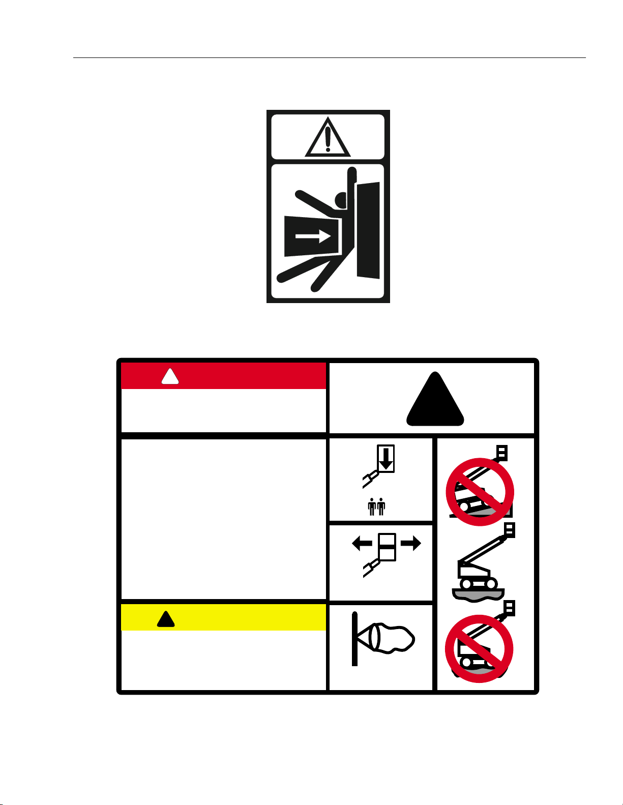
SECTION 3 - USER RESPONSIBILITIES AND MACHINE CONTROL
1701518
1701518
!
DANGER
BEWARE OF LIVE ELECTRICAL CONDUCTORS.
CONTACT THE LOCAL ELECTRICITY AUTHORITIES TO
ENSURE ADEQUATE CLEARANCES.
THIS MACHINE IS NOT ELECTRICALLY INSULATED
DAILY CHECK LIST
1. CHECK TYRES AND THEIR CONDITION.
2. CHECK BOOM AND AXLE CUT-OUT SWITCHES.
3. CHECK SAFETY PROTECTION ITEMS.
4. CHECK ALL OPERATIONS FOR MALFUNCTION.
5. CHECK BRAKES.
6. ENSURE THAT JLG OPERATION AND SAFETY MANUAL IS WITH
THE MACHINE.
7. DO NOT OPERATE A MALFUNCTIONING MACHINE.
8. CHECK THE ENGINE AND DRIVE SPEED CUT-OUT SWITCHES.
9. MAXIMUM OPERATING SLOPE: 3 DEGREES.
!
CAUTION
THIS MACHINE MAY BE OPERATED
BY TRAINED PERSONNEL ONLY.
REFERENCE SHOULD BE MADE TO THE
JLG OPERATION AND SAFETY MANUAL TO
UK
ENSURE SAFE OPERATION OF THIS MACHINE.
!
230kg MAX
+ 70kg
400N MAX
12.5 m/s MAX
1703806 A
1703806 A
3120868 – JLG Lift – 3-13
Page 44

SECTION 3 - USER RESPONSIBILITIES AND MACHINE CONTROL
!
DANGER
BEWARE OF LIVE ELECTRICAL CONDUCTORS.
CONTACT THE LOCAL ELECTRICITY AUTHORITIES TO
ENSURE ADEQUATE CLEARANCES.
THIS MACHINE IS NOT ELECTRICALLY INSULATED
DAILY CHECK LIST
1. CHECK TYRES AND THEIR CONDITION.
2. CHECK BOOM AND AXLE CUT-OUT SWITCHES.
3. CHECK SAFETY PROTECTION ITEMS.
4. CHECK ALL OPERATIONS FOR MALFUNCTION.
5. CHECK BRAKES.
6. ENSURE THAT JLG OPERATION AND SAFETY MANUAL IS WITH THE MACHINE.
7. DO NOT OPERATE A MALFUNCTIONING MACHINE.
8. CHECK THE ENGINE AND DRIVE SPEED CUT-OUT SWITCHES.
9. MAXIMUM OPERATING SLOPE: 3 DEGREES.
!
CAUTION
THIS MACHINE MAY BE OPERATED
BY TRAINED PERSONNEL ONLY.
REFERENCE SHOULD BE MADE TO THE
JLG OPERATION AND SAFETY MANUAL TO
ENSURE SAFE OPERATION OF THIS MACHINE.
UK
1703807 A
1703807 A
1703992 B
3-14 – JLG Lift – 3120868
Page 45

SECTION 3 - USER RESPONSIBILITIES AND MACHINE CONTROL
FUNCTION
DRIVE
SELECT
STEER
SELECT
PLATFORM
LEVEL
CHASSIS
OUT OF
LEVEL
FUNCTIONSYMBOL SYMBOL
MAIN
LIFT
Main
Lift
SWING
FUNCTION
SPEED
CONTROL
PLATFORM
ROTATE
CREEP
PLATFORM
CAPACITY
INDICATOR
ENGINE
DISTRESS
LOW FUEL
LEVEL
AC
GENERATOR
ON
500 LB
1000 LB
TOWER
LIFT
TOWER
TELESCOPE
ARTICULATING
FLY BOOM
MAIN
TELESCOPE
FUEL
SELECT
Figure 3-7. Control Panel Symbols - Sheet 1 of 2
3120868 – JLG Lift – 3-15
Page 46

SECTION 3 - USER RESPONSIBILITIES AND MACHINE CONTROL
FUNCTION
GLOW PLUG
INDICATOR
ENABLE
INDICATOR
POWER
EMERGENCY
STOP
START
AUXILIARY
POWER
FUNCTIONSYMBOL SYMBOL
SOFT
TOUCH
OVERRIDE
SOFT TOUCH
INDICATOR
DRIVE
STEER
Figure 3-8. Control Panel Symbols - Sheet 2 of 2
3-16 – JLG Lift – 3120868
Page 47

SECTION 4 - MACHINE OPERATION
SECTION 4. MACHINE OPERATION
4.1 DESCRIPTION
This machine is a self-propelled aerial work platform on
the end of an elevating, telescoping and rotating boom.
The JLG Lift is intended purpose is to position personnel
with their tools and supplies at positions above ground
level. The machine can be used to reach work areas
located above and over machinery or equipment.
The JLG Lift has a primary operator Control Station in the
platform. From this Control Station, the operator can drive
and steer the machine in both forward and reverse directions. The operator can raise, lower, extend or retract the
boom; swing the boom to the left or right; and when
equipped with a platform rotator, can rotate the platform
around the boom end. Standard boom swing is 357° noncontinuous left and right of the stowed position. The
machine has a Ground Control Station which will override
the Platform Control Station. Ground Controls operate
Tower Lift, Main Boom Lift, Main Boom Telescope and
Swing and are to be used only in an emergency to lower
the platform to the ground should the operator in the platform be unable to do so.
Instruction and hazard warnings are posted adjacent to
both operator control stations and at other places on the
machine. It is extremely important that operators know
what instructions and warnings are placed on the
machine, and review these periodically so that they are
fresh in their minds.
The JLG Lift is designed to provide efficient and safe operation when maintained and operated in accordance with
warnings on the machine, in the Operators and Safety
Manual, and all jobsite and government rules and regulations. As with any type of machinery, the operator is very
important to efficient and safe operation. It is absolutely
necessary that the JLG Lift be regularly maintained in
accordance with this manual and the machine Service
and Maintenance manual, and that any evidence of lack of
maintenance, malfunction, excessive wear, damage or
modification to the machine be reported immediately to
the machine owner or the jobsite supervisor or safety
manager and that the machine be taken out of service
until all discrepancies are corrected.
The JLG Lift is not intended to be used to lift material other
than supplies which personnel in the platform require to
do their job. Supplies or tools which extend outside the
platform are prohibited. It must not be used as a forklift,
crane, support for overhead structure, or to push or pull
another object.
The machine is equipped with an auxiliary battery operated power unit which will provide hydraulic power in the
event of a primary engine power loss. Auxiliary power can
be controlled from either the Platform Control Station or
the Ground Control Station. Follow the instructions placed
at the control stations.
The JLG Lift is hydraulically powered using hydraulic
motors and cylinders for various machine motions. The
hydraulic components are controlled by electrically activated hydraulic valves using switches and control levers.
The speeds of functions controlled by control levers are
variable from zero to maximum speed depending upon
the position of the control lever. Functions controlled by
toggle switches are either on or off and higher or lower
speed is possible when the Function Speed control switch
is used in conjunction with the function toggle switch. A
foot operated switch in the platform must be depressed
before any controls will function and provides a means of
emergency stop when the operator’s foot is removed from
the footswitch.
The JLG Lift is a two wheel drive (four wheel drive available) machine with drive power being supplied by a
hydraulic motor for each drive wheel. Each drive wheel is
supplied with a hydraulically released, spring-applied
brake (4WD machines only have brakes on the rear).
These brakes are automatically applied any time the Drive
Control lever is returned to the neutral position.
The unrestricted capacity of the JLG Lift is 230 kg. (500
lbs.) This means that with a platform load of 230 kg. (500
lbs.) or less, the platform may be positioned anywhere the
boom will reach.
4.2 GENERAL
This section provides the necessary information needed
to operate the machine. Included in this section are the
procedures for starting, stopping, traveling, steering, parking, platform loading and transporting. It is important that
the user read and understand the proper procedures
before operating the machine.
3120868 – JLG Lift – 4-1
Page 48

SECTION 4 - MACHINE OPERATION
4.3 ENGINE OPERATION
NOTE: Initial starting should always be performed from the
Ground Control station.
Starting Procedure
1. Check engine oil. If necessary, add oil in accordance with the Engine Manufacturer’s manual.
2. Check fuel level. Add fuel if necessary.
3. Check that air cleaner components are in place and
securely fastened.
IF ENGINE FAILS TO START PROMPTLY, DO NOT CRANK FOR AN
EXTENDED PERIOD. SHOULD ENGINE FAIL TO START ONCE
AGAIN, ALLOW STARTER TO "COOL OFF" FOR 2-3 MINUTES. IF
ENGINE FAILS AFTER SEVERAL ATTEMPTS, REFER TO ENGINE
MAINTENANCE MANUAL.
NOTE: Machines with diesel engines. After turning on igni-
tion, operator must wait until glow plug indicator light
goes out before cranking engine.
4. Turn key of SELECT switch to GROUND. Position
POWER/EMERGENCY STOP switch to ON, then
push the ENGINE START switch to the upward position until engine starts.
1. Remove all load and allow engine to operate at low
speed setting for 3-5 minutes; this allows for further
reduction of internal engine temperature.
2. Position POWER/EMERGENCY STOP switch to OFF.
3. Turn key of MASTER switch to OFF position.
NOTE: Refer to Engine Manufacturer’s manual for detailed
information.
4.4 TRAVELING (DRIVING)
DO NOT DRIVE WITH BOOM EXTENDED OR ABOVE HORIZONTAL
EXCEPT ON A SMOOTH, FIRM AND LEVEL SURFACE.
TO AVOID LOSS OF TRAVEL CONTROL OR UPSET ON GRADES
AND SIDESLOPES, DO NOT DRIVE MACHINE ON GRADES OR
SIDESLOPES EXCEEDING THOSE SPECIFIED ON MACHINE
INFORMATION PLACARD ON THE LEFT SIDE OF THE FRAME.
TRAVEL GRADES WITH DRIVE SPEED/TORQUE SELECT SWITCH
IN THE FORWARD POSITION. USE EXTREME CAUTION WHEN
DRIVING IN REVERSE AND AT ALL TIMES WHEN DRIVING WITH
PLATFORM ELEVATED AND ESPECIALLY WHEN DRIVING WITH
ANY PART OF MACHINE WITHIN 2 M OF AN OBSTRUCTION. DO
NOT USE DRIVE TO MANEUVER PLATFORM CLOSE TO AN
OBSTRUCTION...USE ONE OF THE BOOM FUNCTIONS.
ALLOW ENGINE TO WARM-UP FOR A FEW MINUTES AT LOW
SPEED BEFORE APPLYING ANY LOAD.
5. After engine has had sufficient time to warm up, shut
engine off.
6. Turn key of SELECT switch to PLATFORM.
7. From Platform position POWER/EMERGENCY
STOP switch to ON, then push the ENGINE START
switch to the forward position until engine starts.
NOTE: Footswitch must be in released (up) position before
starter will operate. If starter operates with footswitch
in the depressed position, DO NOT OPERATE
MACHINE.
Shutdown Procedure
IF AN ENGINE MALFUNCTION NECESSITATES UNSCHEDULED
SHUTDOWN, DETERMINE AND CORRECT CAUSE BEFORE
RESUMING ANY OPERATION.
BEFORE DRIVING, MAKE SURE BOOM IS POSITIONED OVER
REAR AXLE. IF BOOM IS OVER FRONT AXLE (STEER WHEELS),
STEER AND DRIVE CONTROLS WILL MOVE IN OPPOSITE DIRECTIONS TO MACHINE CONTROLS.
Tra ve li n g F or war d o r R ev er se
1. With engine running, depress footswitch and position DRIVE control to FORWARD and hold for the
duration of forward travel desired.
NOTE: When DRIVE or STEER functions are being oper-
ated there is an interlock which prevents operation of
boom functions.
2. Depress footswitch and position DRIVE control to
REVERSE and hold for duration of reverse travel
desired.
3. Depress footswitch and position STEER control to
RIGHT for traveling right and LEFT for traveling left.
4-2 – JLG Lift – 3120868
Page 49

SECTION 4 - MACHINE OPERATION
LEVEL
DO NOT DRIVE MACHINE ON GRADES AND
SIDESLOPES EXCEEDING THOSE SPECIFIED ON
THE SERIAL NUMBER PLACARD.
Figure 4-1. Grade and Sideslope
4. To obtain maximum travel speed, position the DRIVE
controller to FAST and activate the following
switches:
Position DRIVE SPEED/TORQUE SELECT switch to
FAST. (Forward Position)
5. Prior to stopping the machine, position switches as
follows:
Position DRIVE SPEED/TORQUE SELECT switch to
LOW. (Backward Position)
6. For traveling up grades, position switches as follows:
Position DRIVE SPEED/TORQUE SELECT switch to
HIGH.
NOTE: For smoother operation when driving with fully
extended boom, place DRIVE control to SLOW
before stopping.
4.5 STEERING
Depress footswitch to steer machine, push on the left side
of the switch to steer left, on the right side to steer right.
BEFORE OPERATING MACHINE, MAKE SURE BOOM IS POSITIONED OVER REAR AXLE. IF BOOM IS OVER FRONT AXLE
(STEER WHEELS), STEER AND DRIVE CONTROLS WILL MOVE IN
OPPOSITE DIRECTION THAN INDICATED ON MACHINE PLACARDS.
4.6 PARKING AND STOWING
Park and stow machine as follows:
1. Park machine in travel position; boom lowered over
rear, all access panels and doors closed and
secured, ignition off.
2. Check that brakes hold machine in position.
3. Chock wheels front and rear.
4. Turn off SELECT switch and remove key.
4.7 PLATFORM
Loading From Ground Level
1. Position chassis on a smooth, firm and level surface.
2. If total load (personnel, tools and supplies) is less
then rated capacity, distribute load uniformly on platform floor and proceed to work position.
3120868 – JLG Lift – 4-3
Page 50

SECTION 4 - MACHINE OPERATION
Loading From Positions Above Ground Level
Before loading weight to platform above ground level:
1. Determine what the total rated capacity weight will
be after additional weight is loaded (personnel, tools
and supplies).
2. If total weight in platform will be less then rated
capacity, proceed with adding weight.
Platform Level Adjustment
1. Leveling UP. Depress footswitch To raise platform,
position PLATFORM LEVEL control switch UP and
hold until platform is level.
2. Leveling DOWN. Depress footswitch To lower platform, position PLATFORM LEVEL control switch to
DOWN and hold until platform is level.
Platform Rotation
1. Depress footswitch to rotate platform to the left,
PLATFORM ROTATE control is positioned to the
LEFT and held until desired position is reached.
2. Depress footswitch to rotate platform to the right,
PLATFORM ROTATE control is positioned to the
RIGHT and held until desired position is reached.
4.8 BOOM
AN ORANGE TILT WARNING LIGHT IS LOCATED ON THE CONTROL CONSOLE WHICH LIGHTS WHEN THE CHASSIS IS ON A 5
DEGREE OR GREATER SLOPE. DO NOT SWING OR RAISE BOOM
ABOVE HORIZONTAL WHEN LIGHT IS LIT.
DO NOT DEPEND ON TILT ALARM AS A LEVEL INDICATOR FOR
THE CHASSIS. THE TILT ALARM INDICATES THE CHASSIS IS ON
A SEVERE SLOPE (3 DEGREE OR GREATER). CHASSIS MUST BE
LEVEL BEFORE SWINGING, OR RAISING BOOM ABOVE HORIZONTAL.
TO AVOID MACHINE UPSET IF THE ORANGE TILT WARNING
LIGHT ILLUMINATED WHEN THE BOOM IS RAISED ABOVE HORIZONTAL, LOWER THE PLATFORM TO GROUND LEVEL, THEN
REPOSITION MACHINE SO THAT CHASSIS IS LEVEL BEFORE
RAISING BOOM.
TRAVELING WITH BOOM BELOW HORIZONTAL IS PERMITTED
ON GRADES SPECIFIED ON SERIAL NUMBER PLACARD.
TO AVOID SERIOUS INJURY, DO NOT OPERATE MACHINERY IF
ANY CONTROL LEVER OR TOGGLE SWITCH CONTROLLING
PLATFORM MOVEMENT DOES NOT RETURN TO THE "OFF" POSITION WHEN RELEASED.
TO AVOID A COLLISION AND INJURY IF PLATFORM DOES NOT
STOP WHEN A CONTROL SWITCH OR LEVER IS RELEASED,
REMOVE FOOT FROM FOOTSWITCH OR USE EMERGENCY STOP
SWITCH TO STOP MACHINE.
Swinging the Boom
Depress footswitch to swing boom, with footswitch activated, position SWING control switch to RIGHT or LEFT
for direction desired.
WHEN SWINGING THE BOOM MAKE SURE THERE IS AMPLE
ROOM FOR THE BOOM TO CLEAR SURROUNDING WALLS, PARTITIONS AND EQUIPMENT.
Raising and Lowering the Lower and Mid
Boom.
To raise or lower the Lower and Mid Boom, with footswitch
activated, position Lower Boom Lift switch to UP or DOWN
as desired.
4-4 – JLG Lift – 3120868
Page 51

SECTION 4 - MACHINE OPERATION
Raising and Lowering the Main (Upper)
Boom
NOTE: Lift up will not function when the boom is near full
elevation and the platform is out of level.
To raise or lower the Main (Upper) Boom, with footswitch
activated, position Upper Boom Lift switch to UP or
DOWN until desired height is reached.
Telescoping the Main Boom
To extend or retract the main boom, with the footswitch
activated, position the Main Telescope Control Switch to
the in or out position and hold until the platform reaches
the desired position.
4.9 LIFT UP AND PLATFORM LEVEL DOWN DISABLE SWITCH FUNCTIONAL CHECK
The purpose of the disable switch is to prevent lift up
when the boom is near full elevation and the platform is
out of level.
4.10 SHUT DOWN AND PARK
4. Drive machine to a protected area.
5. Assure main boom is fully retracted and lowered
over rear (Drive) axle; all access panels and doors
closed and secured.
6. Remove all load and allow engine to operate 3-5
minutes at LOW setting to permit reduction of
engine internal temperatures.
7. At Ground Controls, turn KEY SELECT switch to
(center) OFF. Position, POWER/EMERGENCY STOP
switch (down) to OFF. Remove key.
8. Cover Platform Control console to protect instruction
placards, warning decals and operating controls
from hostile environment.
4.11 TIE DOWN AND LIFTING
When transporting machine, boom must be in the stowed
mode and machine securely tied down to truck or trailer
deck. Four tie down eyes are provided in the frame slab,
one at each corner of the machine. (See Figure 4-3. and
Figure 4-4.)
PROXIMITY SWITCH
CONTACT PLATE
COIN
Figure 4-2. Functional Check
DISABLE SWITCH FUNCTIONAL CHECK MUST BE PERFORMED
QUARTERLY, ANY TIME A SYSTEM COMPONENT IS REPLACED,
OR WHEN IMPROPER SYSTEM OPERATION IS SUSPECTED.
1. Tape a small piece of metal to the end of the limit
switch (e.g. a coin).
2. Using the controls in the platform basket, test the lift
up and platform level down functions. Both operations should be locked out and not function.
If it becomes necessary to lift the machine using an overhead or mobile crane, it is very important that the lifting
devices are attached only to the designated lifting eyes.
(See Figure 4-5. Lifting Chart)
NOTE: Crane and lifting devices, chains, slings, etc., must
be capable of handling at least:
450A - 2WD (pneumatic tires) - 6668 kg. (14,700 lbs.)
450AJ - 2WD (pneumatic tires) - 7030 kg. (15,500 lbs.)
450A - 2WD (foam-filled tires) - 6985 kg. (15,400 lbs.)
450AJ - 2WD (foam-filled tires) - 7122 kg. (15,700 lbs.)
ABOVE ARE MINIMUM WEIGHTS. CHECK WEIGHT OF UNIT
PRIOR TO LIFTING.
NOTE: Lifting eyes are provided at the front and rear in the
frame slab. Each of the four chains or slings used for
lifting machine must be adjusted individually so
machine remains level when elevated.
3. Remove metal (coin) and return machine to service.
3120868 – JLG Lift – 4-5
Page 52

SECTION 4 - MACHINE OPERATION
Note When transporting machine over rough terrain or long distance, the boom needs to be chocked and
strapped whenever the base boom is unable to rest on its pad. This prevents the boom from bouncing
up and down and preventing possible damage while transporting.
Figure 4-3. Machine Tie Down - A Models
4-6 – JLG Lift – 3120868
Page 53

SECTION 4 - MACHINE OPERATION
Note When transporting machine over rough terrain or long distance, the boom needs to be chocked and
strapped whenever the base boom is unable to rest on its pad. This prevents the boom from bouncing
up and down and preventing possible damage while transporting.
Figure 4-4. Machine Tie Down - AJ Models
3120868 – JLG Lift – 4-7
Page 54

SECTION 4 - MACHINE OPERATION
Figure 4-5. Lifting Chart
4-8 – JLG Lift – 3120868
Page 55

SECTION 4 - MACHINE OPERATION
4.12 OSCILLATING AXLE LOCKOUT TEST (IF EQUIPPED)
LOCKOUT SYSTEM TEST MUST BE PERFORMED QUARTERLY,
ANY TIME A SYSTEM COMPONENT IS REPLACED, OR WHEN
IMPROPER SYSTEM OPERATION IS SUSPECTED.
NOTE: Ensure boom is fully retracted, lowered, and cen-
tered between drive wheels prior to beginning lockout cylinder test.
1. Place a 15 cm high block with ascension ramp in
front of left front wheel.
2. From platform control station, start engine.
3. Place HIGH ENGINE, DRIVE SPEED and WHEEL
MOTOR SPEED (if equipped) control switches to
their respective LOW positions
4. Place DRIVE control lever to FORWARD position
and carefully drive machine up ascension ramp until
left front wheel is on top of block.
5. Carefully activate SWING control lever and position
boom over right side of machine.
6. With boom over right side of machine, place DRIVE
control lever to REVERSE and drive machine off of
block and ramp.
7. Have an assistant check to see that left front wheel
remains locked in position off of ground.
8. Carefully activate SWING control lever and return
boom to stowed position (centered between drive
wheels). When boom reaches center, stowed position, lockout cylinders should release and allow
wheel to rest on ground, it may be necessary activate DRIVE to release cylinders.
9. Place the 15 cm high block with ascension ramp in
front of right front wheel.
10. Place DRIVE control lever to FORWARD and carefully drive machine up ascension ramp until right
front wheel is on top of block.
11. Carefully activate SWING control lever and position
boom over left side of machine.
12. With boom over left side of machine, place DRIVE
control lever to REVERSE and drive machine off of
block and ramp.
13. Have an assistant check to see that right front wheel
remains locked in position off of ground.
14. Carefully activate SWING control lever and return
boom to stowed position (centered between drive
wheels). When boom reaches center, stowed position, lockout cylinders should release and allow
wheel to rest on ground, it may be necessary activate DRIVE to release cylinders.
15. If lockout cylinders do not function properly, have
qualified personnel correct the malfunction prior to
any further operation.
3120868 – JLG Lift – 4-9
Page 56

SECTION 4 - MACHINE OPERATION
4.13 TOWING
RUNAWAY VEHICLE/MACHINE HAZARD. MACHINE HAS NO TOWING BRAKES. TOWING VEHICLE MUST BE ABLE TO CONTROL
MACHINE AT ALL TIMES. ON-HIGHWAY TOWING NOT PERMITTED. FAILURE TO FOLLOW INSTRUCTIONS COULD CAUSE SERIOUS INJURY OR DEATH.
MAXIMUM TOWING SPEED 8 K.M.H. (5 M.P.H.) FOR NO LONGER
THAN 30-45 MINUTES.
MAXIMUM TOWING GRADE 25%.
Prior to towing the machine, complete the
following:
DO NOT TOW MACHINE WITH ENGINE OPERATING OR DRIVE
HUBS ENGAGED.
1. Retract, lower and position boom over rear drive
wheels in line with direction of travel.
2. Disconnect drive hubs by inverting disconnect cap.
(See Figure 4-6.) After towing the machine, complete the following:
3. Reconnect drive hubs by inverting disconnect cap.
(See Figure 4-6.)
Figure 4-6. Drive Disconnect Hub
4-10 – JLG Lift – 3120868
Page 57

SECTION 5 - OPTIONAL EQUIPMENT
SECTION 5. OPTIONAL EQUIPMENT
5.1 DUAL FUEL SYSTEM (GAS ENGINE ONLY)
Description
The dual fuel system enables the standard gasoline
engine to run on either gasoline or LP gas. The system
includes pressurized cylinders mounted on the frame, and
the valves and switches needed to switch the fuel supply
from gasoline to LP gas or from LP gas to gasoline.
A two position, FUEL SELECT toggle switch at the platform control station supplies electrical power to open the
gasoline shut-off solenoid and close the LP gas shut off
solenoid when positioned to the GASOLINE position. This
switch supplies electrical power to open the LP gas shutoff solenoid and close the gasoline shut-off solenoid when
positioned to the LP position.
IT IS POSSIBLE TO SWITCH FROM ONE FUEL SOURCE TO THE
OTHER WITHOUT ALLOWING THE ENGINE TO STOP. EXTREME
CARE MUST BE TAKEN AND THE FOLLOWING INSTRUCTIONS
MUST BE FOLLOWED.
Changing From Gasoline to LP Gas
5.3 PLATFORM W/SOFT TOUCH PROXIMITY SYSTEM BUMPER
This optional system incorporates a lower padded rail,
slightly larger than the platform. Four Proximity switches
are attached to each corner of the lower rail. The proximity
switches are set so that when the antenna comes into
contact with an object, electrical power is cut off from the
platform controls, shutting down all functions.
5.4 FOUR WHEEL DRIVE
Provides drive motors, brakes (rear only) and torque hubs
at each wheel to give extra traction. The system is available with either a fixed or oscillating front axle.
5.5 COLD WEATHER PACKAGE
Deutz Engine with Glow Plugs
The glow plugs are installed in the engine and automatically come on with the ignition circuit and remain on for a
period of seven seconds.
1. Start engine from Ground Control Station.
2. Open hand valve on LP gas supply tank by turning
counterclockwise.
3. While engine is operating on GASOLINE under a noload condition, place FUEL SELECT switch at Platform Control to LP position.
Changing From LP Gas to Gasoline
1. With engine operating on LP under a no-load condition, position FUEL SELECT switch at Platform Control Station to GASOLINE position.
2. Close hand valve on LP gas supply tank by turning
clockwise.
5.2 OSCILLATING AXLE
The oscillating front axle is attached to the frame by a
pivot pin which allows all four wheels to remain on the
ground when traveling on rough terrain. The oscillating
axle also incorporates two lockout cylinders connected
between the frame and each wheel end. The lockout cylinders permit axle oscillation when the boom is centered
over the rear, and lock and hold the axle when the boom is
moved off center.
In addition to the glow plugs, the cold weather package
also includes an electric immersion heater for the hydraulic oil tank, and an electric blanket type heater for the battery. These components can be plugged in together or
singly to preheat their associated components for easier
cold weather starting.
3120868 – JLG Lift – 5-1
Page 58

SECTION 5 - OPTIONAL EQUIPMENT
Deutz Engine with Ether Start
The ether start system in the diesel engine functions automatically to provide starting fluid, as necessary, to the
engine. A sensor switch mounted on the engine will permit ether injection when the engine is cold. The sensor will
not permit ether injection to a warm engine.
In addition to the ether start system, the cold weather
package also includes an electric immersion heater for the
hydraulic oil tank, and an electric blanket type heater for
the battery. These components can be plugged in
together or singly to preheat their associated components
for easier cold weather starting.
Isuzu Engine
The cold weather package for the Isuzu engine consists of
the engine block heater (an electrical heater installed in
the left front core plug hole), an electric immersion heater
for the hydraulic oil tank, and an electric blanket type
heater for the battery. These components can be plugged
in together or singly to preheat their associated components for easier cold weather starting.
Ford Engine
Two different options are available for cold weather with
the Ford engine; an engine block heater and a cold
weather package which also includes the engine block
heater.
5.6 TRAVEL ALARM
A 12-volt alarm horn, mounted on the turntable, provides
an audible warning when the machine is in the travel
(DRIVE) mode. It will function in FORWARD or REVERSE
to warn jobsite personnel the machine is traveling.
5.7 ELECTRIC GENERATOR
An electric generator mounted on the machine functions
to supply electrical power to the platform. This device will
provide enough power to run assorted power tools.
5.8 ROTATING BEACON
An amber or red rotating beacon may be installed on the
hood or platform, and can be controlled by a two position
toggle switch mounted on the platform control console.
When the switch is placed in the ON position, the light is
activated and provides a visual warning to the machine’s
operation.
5.9 CYLINDER BELLOWS
A one piece accordion shaped rubber bellows may be
attached to the rod end of the cylinder barrel and to the
cylinder rod as close to the rod attach bushing as possible. The bellows affords protection to the cylinder rod in
either the extended or retracted position. The bellows are
installed on the lift cylinder, slave cylinder, master cylinder
and steer cylinder.
5.10 BOOM WIPERS
A one piece U-shaped neoprene strip, be attached to the
front of the base boom section, wipes the top and both
sides of the fly section. The bottom side of the fly section
is protected by a straight neoprene strip which also
attaches to the base section.
The engine block heater is an electrical heater installed in
the left (intake side) core plug hole. When plugged in, it
heats the engine coolant to warm the engine prior to starting.
The cold weather package consists of the engine block
heater mentioned above, an immersion heater for the
hydraulic oil tank, and an electric blanket type heater for
the battery. These components can be plugged in
together or singly to preheat their associated components
for easier cold weather starting.
5-2 – JLG Lift – 3120868
Page 59

SECTION 5 - OPTIONAL EQUIPMENT
5.11 HOSTILE ENVIRONMENT PACKAGE
The hostile environment package provides additional protection against the entry of dust, dirt, sand and other abrasive materials into the hydraulic system, control handles
and switches, cylinders, boom wire ropes and wear pads,
and the air inlet of the engine. The package is intended for
machines that will be exposed to painting, sandblasting or
other similar hostile conditions. The hostile environment
package includes boom wipers, cylinder bellows, heavy
duty reservoir breather, an engine air cleaner and control
console cover, as required.
5.12 MOTION ALARM
A motion alarm horn provides an audible warning when
the platform controls are selected at the PLATFORM/
GROUND SELECT switch, the POWER/EMERGENCY
STOP switch is ON, and the footswitch is depressed. The
alarm warns personnel in the jobsite area to avoid the
operating machine.
5.13 SEMI-TRACK
The semi-track option consists of steel tracks and idler
wheels. The idler wheels are mounted to the chassis just
forward of the drive wheels. The steel tracks are installed
around the drive wheels and idler wheels. This option provides increased traction for operation in rough terrain.
Updated 2-16-00
3120868 – JLG Lift – 5-3
Page 60

SECTION 5 - OPTIONAL EQUIPMENT
This page left blank intentionally.
5-4 – JLG Lift – 3120868
Page 61

SECTION 6 - EMERGENCY PROCEDURES
SECTION 6. EMERGENCY PROCEDURES
6.1 GENERAL
This section provides information on the procedures to be
followed and on the systems and controls to be used in
the event an emergency situation is encountered during
machine operation. Prior to operation of the machine and
periodically thereafter, the entire operating manual, including this section, should be reviewed by all personnel
whose responsibilities include any work or contact with
the machine.
6.2 EMERGENCY TOWING PROCEDURES
Towing this machine is prohibited, unless properly
equipped. However, provisions for moving the machine, in
case of a malfunction or power failure, have been incorporated. The following procedures are to be used ONLY for
emergency movement to a suitable maintenance area.
1. Chock wheels securely.
2. Disengage drive hubs by reversing disconnect caps.
3. Connect suitable equipment, remove chocks, and
move machine.
After moving machine, complete the following procedures:
1. Position machine on a firm and level surface.
2. Chock wheels securely.
3. Engage drive hubs by reversing disconnect caps on
hubs.
4. Remove chocks from wheels as needed.
2. Installed on the Platform Console, this round red
switch is pulled up for normal machine functions. In
an emergency, push the button to the down position
with your palm and machine will immediately stop.
Ground Control Station
The Ground Control Station is located on the right front
side of the turntable. The controls on this panel provide
the means for overriding the platform controls, and for
controlling the boom and swing functions from the
ground. Place the KEY SELECT switch to GROUND position and operate the proper switch to lift, swing, or telescope the boom, or level the platform.
Auxiliary Power
A toggle type auxiliary power control switch is located on
the platform control station and another is located on the
ground control station. Operation of either switch turns on
the electrically driven auxiliary hydraulic pump. This
should be used in case of failure of the main power plant.
The auxiliary pump will operate boom lift, telescope and
swing. To activate auxiliary power:
1. Position PLATFORM/GROUND SELECT KEY
SWITCH to PLATFORM.
2. Position POWER/EMERGENCY STOP switch to ON.
3. Depress and hold footswitch.
4. Operate appropriate control switch, lever or controller for desired function and hold.
5. Position AUXILIARY POWER switch to ON and hold.
6. Release AUXILIARY POWER switch, selected control
switch, lever or controller, and footswitch.
6.3 EMERGENCY CONTROLS AND THEIR LOCATIONS
Power/Emergency Stop Switches
1. There is one of these red mushroom shaped
switches at both the Ground Controls and Platform
Controls. When depressed it will immediately stop
the machine.
CHECK MACHINE DAILY TO MAKE SURE EMERGENCY STOP
SWITCH GUARD IS IN PLACE AND THAT GROUND CONTROL
INSTRUCTIONS ARE IN PLACE AND LEGIBLE.
7. Position POWER/EMERGENCY STOP switch to OFF.
To activate auxiliary power from the ground control station:
1. Position PLATFORM/GROUND SELECT KEY
SWITCH to GROUND.
2. Position POWER/EMERGENCY STOP switch to ON.
3. Operate appropriate control switch or controller for
desired function and hold.
4. Position AUXILIARY POWER switch to ON and hold.
5. Release AUXILIARY POWER switch, and appropriate
control switch or controller.
6. Position POWER/EMERGENCY STOP switch to OFF.
3120868 – JLG Lift – 6-1
Page 62

SECTION 6 - EMERGENCY PROCEDURES
6.4 EMERGENCY OPERATION
Use of Ground Controls
KNOW HOW TO USE THE GROUND CONTROLS IN AN
EMERGENCY SITUATION.
Ground personnel must be thoroughly familiar with the
machine operating characteristics and the ground control
functions. Training should include operation of the
machine, review and understanding of this section and
hands-on operation of the controls in simulated emergencies.
Operator Unable to Control Machine
IF THE PLATFORM OPERATOR IS PINNED, TRAPPED OR
UNABLE TO OPERATE OR CONTROL THE MACHINE:
DO NOT OPERATE WITH PRIMARY POWER SOURCE (ENGINE OR
ELECTRIC MOTOR) IF PERSONS ARE PINNED OR TRAPPED. USE
AUXILIARY POWER INSTEAD.
1. Operate the machine from ground controls ONLY
with the assistance of other personnel and equipment (cranes, overhead hoists, etc.) as may be be
required to safely remove the danger or emergency
condition.
2. Other qualified personnel on the platform may use
the platform controls with regular or auxiliary power.
DO NOT CONTINUE OPERATION IF CONTROLS
DO NOT FUNCTION NORMALLY.
3. Cranes, forklift trucks or other equipment which may
be available are to be used to remove platform
occupants and stabilize motion of the machine in
case machine controls are inadequate or malfunction when used.
Platform or Boom Caught Overhead
If the platform or boom becomes jammed or snagged in
overhead structures or equipment, do not continue operation of the machine from either the platform or the ground
until the operator and all personnel are safely moved to a
secure location. Only then should an attempt be made to
free the platform using any necessary equipment and personnel. Do not operate controls to cause one or more
wheels to leave the ground.
Post Incident Inspection and Repair
Following any incident, thoroughly inspect the machine
and test all functions first from the ground controls, then
from the platform controls. Do not lift above 3 m (10 feet)
until you are sure that all damage has been repaired, if
required, and that all controls are operating correctly.A
cold weather start system in the diesel engine functions
automatically to provide starting fluid, as necessary, to the
engine. A sensor switch mounted on the engine will permit ether injection when the engine is cold. The sensor will
not permit ether injection to a warm engine.
6.5 INCIDENT NOTIFICATION
It is imperative that JLG Industries, Inc. be notified immediately of any incident involving a JLG product. Even if no
injury or property damage is evident, the factory should
be contacted by telephone and provided with all necessary details.
Contact your local JLG office.
It should be noted that failure to notify the manufacturer of
an incident involving a JLG Industries product within 48
hours of such an occurrence may void any warranty consideration on that particular machine.
6-2 – JLG Lift – 3120868
Page 63

SECTION 7 - INSPECTION AND REPAIR LOG
SECTION 7. INSPECTION AND REPAIR LOG
Table 7-1.Inspection and Repair Log
Date Comments
3120868 – JLG Lift – 7-1
Page 64

SECTION 7 - INSPECTION AND REPAIR LOG
Table 7-1.Inspection and Repair Log
Date Comments
7-2 – JLG Lift – 3120868
Page 65

To: JLG, Gradall, Lull and Sky Trak product owner:
If you now own, but ARE NOT the original purchaser of the product covered by this manual, we would like
to know who you are. For the purpose of receiving safety-related bulletins, it is very important to keep JLG
Industries, Inc. updated with the current ownership of all JLG products. JLG maintains owner information for each
JLG product and uses this information in cases where owner notification is necessary.
Please use this form to provide JLG with updated information with regard to the current ownership of JLG
Products. Please return completed form to the JLG Product Safety & Reliability Department via facsimile (717) 4856573 or mail to address as specified on the back of this form.
NOTE: Leased or rented units should not be included on this form.
Mfg. Model:
Serial Number:
Previous Owner:
Address:
City: State:
Zip: Telephone: ( )
Date Of Transfer:
Current Owner:
Address:
City: State:
Zip: Telephone: ( )
Who in your organization should we notify?
Name:
Title:
JLG Industries, Inc.
TRANSFER OF OWNERSHIP
Thank you,
Product Safety & Reliability Department
JLG IIndustries, IInc.
1 JLG Drive
McConnellsburg, PA 17233-9533
Telephone: (717) 485-5161
Fax: (717) 485-6573
Please cut on the dotted line and fax to 717-485-6573
Page 66

Page 67

McConnellsburg PA. 17233-9533
Customer Support Toll Free: (877) 554-5438
JLG Worldwide Locations
Corporate Office
JLG Industries, Inc.
1 JLG Drive
USA
Phone: (717) 485-5161
Fax: (717) 485-6417
JLG Industries (Australia)
P.O. Box 5119
11 Bolwarra Road
Port Macquarie
N.S.W. 2444
Australia
Phone: (61) 2 65 811111
Fax: (61) 2 65 810122
JLG Latino Americana Ltda.
Rua Eng. Carlos Stevenson,
80-Suite 71
13092-310 Campinas-SP
Brazil
Phone: (55) 19 3295 0407
Fax: (55) 19 3295 1025
JLG Industries (Europe)
Kilmartin Place,
Tannochside Park
Uddingston G71 5PH
Scotland
Phone: (44) 1 698 811005
Fax: (44) 1 698 811055
JLG Industries (UK)
Unit 12, Southside
Bredbury Park Industrial Estate
Bredbury
Stockport
SK6 2sP
England
Phone: (44) 870 200 7700
Fax: (44) 870 200 7711
JLG Europe B.V.
Jupiterstraat 234
2132 HJ Foofddorp
The Netherlands
Phone: (31) 23 565 5665
Fax: (31) 23 557 2493
JLG Industries (Pty) Ltd.
Unit 1, 24 Industrial Complex
Herman Street
Meadowdale
Germiston
South Africa
Phone: (27) 11 453 1334
Fax: (27) 11 453 1342
JLG Deutschland GmbH
Max Planck Strasse 21
D-27721 Ritterhude/lhlpohl
Bei Bremen
Germany
Phone: (49) 421 693 500
Fax: (49) 421 693 5035
JLG Industries (Norge AS)
Sofeimyrveien 12
N-1412 Sofienyr
Norway
Phone: (47) 6682 2000
Fax: (47) 6682 2001
Plataformas Elevadoras
JLG Iberica, S.L.
Trapadella, 2
P.I. Castellbisbal Sur
08755Castellbisbal
Spain
Phone: (34) 93 77 24700
Fax: (34) 93 77 11762
JLG Industries (Italia)
Via Po. 22
20010 Pregnana Milanese - MI
Italy
Phone: (39) 02 9359 5210
Fax: (39) 02 9359 5845
JLG Polska
UI. Krolewska
00-060 Warsawa
Pol an d
Phone: (48) 91 4320 245
Fax: (48) 91 4358 200
JLG Industries (Sweden)
Enkopingsvagen 150
Box 704
SE - 175 27 Jarfalla
Sweden
Phone: (46) 8 506 59500
Fax: (46) 8 506 59534
Page 68

 Loading...