

Page 1
®
Operation and Safety Manual
Original Instructions - Keep this manual with the machine at all times.
Boom Lift Models
400S
460SJ
S/N 0300203771*
to Present
* See inside front cover for exceptions.
ANSI
3121670
January 19, 2016
Page 2

This manual also covers the following Serial Numbers.
0300184729
0300200144
0300200145
0300200476
0300200477
0300202446
0300202447
0300202448
0300202449
0300202450
0300203261
0300203262
0300203307
0300203308
0300203351
0300203352
0300203394
0300203395
0300203439
0300203440
0300203580
0300203581
0300203582
0300203583
0300203584
0300203628
0300203629
0300203630
0300203631
0300203632
0300203677
0300203678
0300203679
0300203680
0300203681
0300203724
0300203725
0300203727
0300203728
Page 3

FOREWORD
FOREWORD
This manual is a very important tool! Keep it with the machine at all times.
The purpose of this manual is to provide owners, users, operators, lessors, and lessees with the precautions and operating
procedures essential for the safe and proper machine operation for its intended purpose.
Due to continuous product improvements, JLG Industries, Inc. reserves the right to make specification changes without
prior notification. Contact JLG Industries, Inc. for updated information.
3121670 – JLG Lift – a
Page 4
FOREWORD
IMPORTANT
SAFETY ALERT SYMBOLS AND SAFETY SIGNAL WORDS
This is the Safety Alert Symbol. It is used to alert you to the potential personal injury
hazards. Obey all safety messages that follow this symbol to avoid possible injury or
death
INDICATES AN IMMINENTLY HAZARDOUS SITUATION. IF NOT AVOIDED, WILL
RESULT IN SERIOUS INJURY OR DEATH. THIS DECAL WILL HAVE A RED BACKGROUND.
INDICATES A POTENTIALLY HAZARDOUS SITUATION. IF NOT AVOIDED, COULD
RESULT IN SERIOUS INJURY OR DEATH. THIS DECAL WILL HAVE AN ORANGE BACKGROUND.
INDICATES A POTENTIALLY HAZARDOUS SITUATION. IF NOT AVOIDED, MAY RESULT
IN MINOR OR MODERATE INJURY. IT MAY ALSO ALERT AGAINST UNSAFE PRACTICES.
THIS DECAL WILL HAVE A YELLOW BACKGROUND.
INDICATES INFORMATION OR A COMPANY POLICY THAT RELATES DIRECTLY OR INDIRECTLY TO THE SAFETY OF PERSONNEL OR PROTECTION OF PROPERTY.
b – JLG Lift – 3121670
Page 5

THIS PRODUCT MUST COMPLY WITH ALL SAFETY RELATED BULLETINS. CONTACT JLG
IMPORTANT
IMPORTANT
INDUSTRIES, INC. OR THE LOCAL AUTHORIZED JLG REPRESENTATIVE FOR INFORMATION REGARDING SAFETY-RELATED BULLETINS WHICH MAY HAVE BEEN ISSUED FOR
THIS PRODUCT.
JLG INDUSTRIES, INC. SENDS SAFETY RELATED BULLETINS TO THE OWNER OF
RECORD OF THIS MACHINE. CONTACT JLG INDUSTRIES, INC. TO ENSURE THAT THE
CURRENT OWNER RECORDS ARE UPDATED AND ACCURATE.
JLG INDUSTRIES, INC. MUST BE NOTIFIED IMMEDIATELY IN ALL INSTANCES WHERE
JLG PRODUCTS HAVE BEEN INVOLVED IN AN ACCIDENT INVOLVING BODILY INJURY
OR DEATH OF PERSONNEL OR WHEN SUBSTANTIAL DAMAGE HAS OCCURRED TO PERSONAL PROPERTY OR THE JLG PRODUCT.
For:
• Accident Reporting
• Product Safety Publications
• Current Owner Updates
• Questions Regarding
Product Safety
Contact:
Product Safety and Reliability Department
JLG Industries, Inc.
13224 Fountainhead Plaza
Hagerstown, MD 21742
USA
or Your Local JLG Office
(See addresses on inside of manual cover)
In USA:
Toll Free: 877-JLG-SAFE (877-554-7233)
Outside USA:
Phone: 240-420-2661
Fax: 301-745-3713
E-mail: ProductSafety@JLG.com
FOREWORD
• Standards and Regulations
Compliance Information
• Questions Regarding Special
Product Applications
• Questions Regarding Product Modifications
3121670 – JLG Lift – c
Page 6

FOREWORD
Original Issue - March 12, 2015
Revised - March 21, 2015
Revised - April 2, 2015
Revised - July 30, 2015
Revised - January 19, 2016
REVISION LOG
d – JLG Lift – 3121670
Page 7

TABLE OF CONTENTS
SECTION - PARAGRAPH, SUBJECT PAGE SECTION - PARAGRAPH, SUBJECT PAGE
SECTION - 1 - SAFETY PRECAUTIONS
1.1 GENERAL . . . . . . . . . . . . . . . . . . . . . . . . . . . . . . . . . . . . . . . . . . . . 1-1
1.2 PRE-OPERATION . . . . . . . . . . . . . . . . . . . . . . . . . . . . . . . . . . . . . 1-1
Operator Training and Knowledge . . . . . . . . . . . . . . . . . 1-1
Workplace Inspection. . . . . . . . . . . . . . . . . . . . . . . . . . . . . . 1-2
Machine Inspection. . . . . . . . . . . . . . . . . . . . . . . . . . . . . . . . 1-3
1.3 OPERATION. . . . . . . . . . . . . . . . . . . . . . . . . . . . . . . . . . . . . . . . . . 1-3
General . . . . . . . . . . . . . . . . . . . . . . . . . . . . . . . . . . . . . . . . . . . 1-3
Trip and Fall Hazards. . . . . . . . . . . . . . . . . . . . . . . . . . . . . . . 1-4
Electrocution Hazards . . . . . . . . . . . . . . . . . . . . . . . . . . . . . 1-5
Tipping Hazards . . . . . . . . . . . . . . . . . . . . . . . . . . . . . . . . . . . 1-7
Crushing and Collision Hazards . . . . . . . . . . . . . . . . . . 1-10
1.4 TOWING, LIFTING, AND HAULING. . . . . . . . . . . . . . . . . . . . 1-11
1.5 MAINTENANCE. . . . . . . . . . . . . . . . . . . . . . . . . . . . . . . . . . . . . .1-11
Maintenance Hazards. . . . . . . . . . . . . . . . . . . . . . . . . . . . 1-11
Battery Hazards. . . . . . . . . . . . . . . . . . . . . . . . . . . . . . . . . . 1-13
SECTION - 2 - USER RESPONSIBILITIES, MACHINE PREPARATION,
AND INSPECTION
2.1 PERSONNEL TRAINING . . . . . . . . . . . . . . . . . . . . . . . . . . . . . . . 2-1
Operator Training . . . . . . . . . . . . . . . . . . . . . . . . . . . . . . . . . 2-1
Training Supervision . . . . . . . . . . . . . . . . . . . . . . . . . . . . . . . 2-1
Operator Responsibility . . . . . . . . . . . . . . . . . . . . . . . . . . . . 2-1
2.2 PREPARATION, INSPECTION, AND MAINTENANCE . . . . . 2-2
Pre-Start Inspection . . . . . . . . . . . . . . . . . . . . . . . . . . . . . . . 2-4
Function Check. . . . . . . . . . . . . . . . . . . . . . . . . . . . . . . . . . . . 2-5
SkyGuard Function Test. . . . . . . . . . . . . . . . . . . . . . . . . . . . 2-6
General . . . . . . . . . . . . . . . . . . . . . . . . . . . . . . . . . . . . . . . . . . . 2-9
2.3 OSCILLATING AXLE LOCKOUT TEST (IF EQUIPPED). . . . 2-11
SECTION - 3 - MACHINE CONTROLS AND INDICATORS
3.1 GENERAL . . . . . . . . . . . . . . . . . . . . . . . . . . . . . . . . . . . . . . . . . . . . 3-1
3.2 CONTROLS AND INDICATORS . . . . . . . . . . . . . . . . . . . . . . . . 3-1
Ground Control Console . . . . . . . . . . . . . . . . . . . . . . . . . . . 3-2
Ground Control Indicator Panel . . . . . . . . . . . . . . . . . . . . 3-9
Ground Control Console Display Gauge . . . . . . . . . . 3-12
Platform Console . . . . . . . . . . . . . . . . . . . . . . . . . . . . . . . . 3-15
Platform Control Indicator Panel . . . . . . . . . . . . . . . . . 3-21
SECTION - 4 - MACHINE OPERATION
4.1 DESCRIPTION . . . . . . . . . . . . . . . . . . . . . . . . . . . . . . . . . . . . . . . . 4-1
4.2 BOOM OPERATING CHARACTERISTICS AND
LIMITATIONS . . . . . . . . . . . . . . . . . . . . . . . . . . . . . . . . . . . . . . . . 4-2
Capacities . . . . . . . . . . . . . . . . . . . . . . . . . . . . . . . . . . . . . . . . . 4-2
Stability . . . . . . . . . . . . . . . . . . . . . . . . . . . . . . . . . . . . . . . . . . . 4-2
3121670 – JLG Lift – i
Page 8

TABLE OF CONTENTS
SECTION - PARAGRAPH, SUBJECT PAGE SECTION - PARAGRAPH, SUBJECT PAGE
4.3 ENGINE OPERATION . . . . . . . . . . . . . . . . . . . . . . . . . . . . . . . . . 4-2
Starting Procedure . . . . . . . . . . . . . . . . . . . . . . . . . . . . . . . . 4-2
Shutdown Procedure . . . . . . . . . . . . . . . . . . . . . . . . . . . . . . 4-4
Fuel Reserve / Shut-Off System (Diesel
Engines Only) . . . . . . . . . . . . . . . . . . . . . . . . . . . . . . . . . . . 4-4
4.4 TRAVELING (DRIVING). . . . . . . . . . . . . . . . . . . . . . . . . . . . . . . . 4-7
Traveling Forward and Reverse . . . . . . . . . . . . . . . . . . . . 4-9
Traveling on a Grade . . . . . . . . . . . . . . . . . . . . . . . . . . . . . 4-10
4.5 STEERING. . . . . . . . . . . . . . . . . . . . . . . . . . . . . . . . . . . . . . . . . . . 4-10
4.6 PLATFORM . . . . . . . . . . . . . . . . . . . . . . . . . . . . . . . . . . . . . . . . . 4-10
Platform Level Adjustment . . . . . . . . . . . . . . . . . . . . . . . 4-10
Platform Rotation . . . . . . . . . . . . . . . . . . . . . . . . . . . . . . . . 4-10
4.7 BOOM . . . . . . . . . . . . . . . . . . . . . . . . . . . . . . . . . . . . . . . . . . . . . . 4-11
Swinging the Boom . . . . . . . . . . . . . . . . . . . . . . . . . . . . . . 4-11
Raising and Lowering the Main Boom . . . . . . . . . . . . . 4-11
Telescoping the Main Boom . . . . . . . . . . . . . . . . . . . . . . 4-11
4.8 FUNCTION SPEED CONTROL . . . . . . . . . . . . . . . . . . . . . . . . 4-12
4.9 MACHINE SAFETY SYSTEM OVERRIDE
(MSSO)(CE ONLY) . . . . . . . . . . . . . . . . . . . . . . . . . . . . . . . . . . 4-12
4.10 SKYGUARD OPERATION . . . . . . . . . . . . . . . . . . . . . . . . . . . . . 4-13
4.11 SHUT DOWN AND PARK. . . . . . . . . . . . . . . . . . . . . . . . . . . . . 4-14
Shut Down and Park. . . . . . . . . . . . . . . . . . . . . . . . . . . . . . 4-14
4.12 LIFTING AND TIE DOWN . . . . . . . . . . . . . . . . . . . . . . . . . . . . . 4-14
Lifting. . . . . . . . . . . . . . . . . . . . . . . . . . . . . . . . . . . . . . . . . . . . 4-14
Tie Down. . . . . . . . . . . . . . . . . . . . . . . . . . . . . . . . . . . . . . . . . 4-15
SECTION - 5 - EMERGENCY PROCEDURES
5.1 GENERAL . . . . . . . . . . . . . . . . . . . . . . . . . . . . . . . . . . . . . . . . . . . . 5-1
5.2 INCIDENT NOTIFICATION. . . . . . . . . . . . . . . . . . . . . . . . . . . . . 5-1
5.3 EMERGENCY OPERATION . . . . . . . . . . . . . . . . . . . . . . . . . . . . 5-1
Operator Unable to Control Machine. . . . . . . . . . . . . . . 5-1
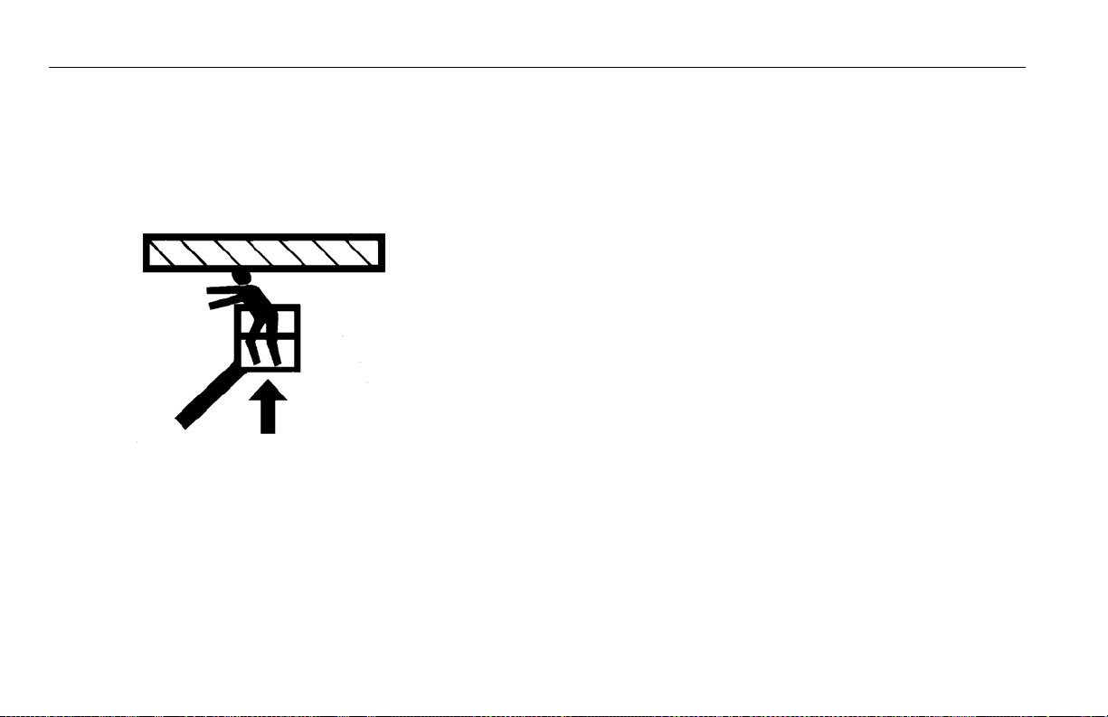
Platform or Boom Caught Overhead . . . . . . . . . . . . . . . 5-2
5.4 EMERGENCY TOWING PROCEDURES. . . . . . . . . . . . . . . . . . 5-2
5.5 MACHINE SAFETY SYSTEM OVERRIDE
(MSSO)(CE ONLY) . . . . . . . . . . . . . . . . . . . . . . . . . . . . . . . . . . . 5-3
SECTION - 6 - GENERAL SPECIFICATIONS & OPERATOR
MAINTENANCE
6.1 INTRODUCTION. . . . . . . . . . . . . . . . . . . . . . . . . . . . . . . . . . . . . . 6-1
6.2 OPERATING SPECIFICATIONS. . . . . . . . . . . . . . . . . . . . . . . . . 6-1
Capacities. . . . . . . . . . . . . . . . . . . . . . . . . . . . . . . . . . . . . . . . . 6-3
Engine Data. . . . . . . . . . . . . . . . . . . . . . . . . . . . . . . . . . . . . . . 6-4
Tires . . . . . . . . . . . . . . . . . . . . . . . . . . . . . . . . . . . . . . . . . . . . . . 6-5
Hydraulic Oil . . . . . . . . . . . . . . . . . . . . . . . . . . . . . . . . . . . . . . 6-6
Critical Stability Weights. . . . . . . . . . . . . . . . . . . . . . . . . . . 6-9
Serial Number Location. . . . . . . . . . . . . . . . . . . . . . . . . . . 6-10
6.3 OPERATOR MAINTENANCE . . . . . . . . . . . . . . . . . . . . . . . . . . 6-19
ii – JLG Lift – 3121670
Page 9

TABLE OF CONTENTS
SECTION - PARAGRAPH, SUBJECT PAGE SECTION - PARAGRAPH, SUBJECT PAGE
6.4 TIRES & WHEELS. . . . . . . . . . . . . . . . . . . . . . . . . . . . . . . . . . . . .6-30
Tire Inflation. . . . . . . . . . . . . . . . . . . . . . . . . . . . . . . . . . . . . 6-30
Tire Damage. . . . . . . . . . . . . . . . . . . . . . . . . . . . . . . . . . . . . 6-30
Tire Replacement . . . . . . . . . . . . . . . . . . . . . . . . . . . . . . . . 6-30
Wheel Replacement . . . . . . . . . . . . . . . . . . . . . . . . . . . . . 6-31
Wheel Installation . . . . . . . . . . . . . . . . . . . . . . . . . . . . . . . 6-31
6.5 PROPANE FUEL FILTER REPLACEMENT . . . . . . . . . . . . . . . 6-33
Removal. . . . . . . . . . . . . . . . . . . . . . . . . . . . . . . . . . . . . . . . . 6-33
Installation . . . . . . . . . . . . . . . . . . . . . . . . . . . . . . . . . . . . . . 6-33
6.6 PROPANE FUEL SYSTEM PRESSURE RELIEF . . . . . . . . . . . 6-34
6.7 SUPPLEMENTAL INFORMATION . . . . . . . . . . . . . . . . . . . . .6-35
SECTION - 7 - INSPECTION AND REPAIR LOG
3121670 – JLG Lift – iii
Page 10

TABLE OF CONTENTS
SECTION - PARAGRAPH, SUBJECT PAGE SECTION - PARAGRAPH, SUBJECT PAGE
This Page Left Blank Intentionally.
iv – JLG Lift – 3121670
Page 11

LIST OF FIGURES
FIGURE NUMBER - TITLE PAGE FIGURE NUMBER - TITLE PAGE
2-1. Basic Nomenclature. . . . . . . . . . . . . . . . . . . . . . . . . . . . . . . . . . 2-7
2-2. Daily Walk-Around Inspection - Sheet 1 of 3 . . . . . . . . . . 2-8
2-3. Daily Walk-Around Inspection - Sheet 2 of 3 . . . . . . . . . . 2-9
2-4. Daily Walk-Around Inspection - Sheet 3 of 3 . . . . . . . . .2-10
3-1. Ground Control Console - 400S. . . . . . . . . . . . . . . . . . . . . . . 3-3
3-2. Ground Control Console - 400S w/MSSO (CE Only) . . . . 3-4
3-3. Ground Control Console - 460SJ . . . . . . . . . . . . . . . . . . . . . . 3-5
3-4. Ground Control Console - 460SJ w/MSSO (CE Only) . . . 3-6
3-5. Ground Control Indicator Panel . . . . . . . . . . . . . . . . . . . . .3-10
3-6. Splash Screen. . . . . . . . . . . . . . . . . . . . . . . . . . . . . . . . . . . . . . .3-12
3-7. Diagnostic Screen. . . . . . . . . . . . . . . . . . . . . . . . . . . . . . . . . . . 3-13
3-8. Engine Diagnostic Screen . . . . . . . . . . . . . . . . . . . . . . . . . . . 3-13
3-9. Ground Control Console Display Gauge . . . . . . . . . . . . .3-14
3-10. Platform Control Console . . . . . . . . . . . . . . . . . . . . . . . . . . . 3-16
3-11. Platform Control Indicator Panel. . . . . . . . . . . . . . . . . . . . . 3-22
3-12. Fuel Level Indicator . . . . . . . . . . . . . . . . . . . . . . . . . . . . . . . . . 3-24
4-1. Position of Least Forward Stability . . . . . . . . . . . . . . . . . . . . 4-5
4-2. Position of Least Backward Stability . . . . . . . . . . . . . . . . . . 4-6
4-3. Grade and Side Slopes . . . . . . . . . . . . . . . . . . . . . . . . . . . . . . . 4-8
4-4. Traveling on a Grade . . . . . . . . . . . . . . . . . . . . . . . . . . . . . . . . 4-10
4-5. Lifting and Tie Down Chart . . . . . . . . . . . . . . . . . . . . . . . . . . 4-16
4-6. Decal Location Sheet 1 of 7. . . . . . . . . . . . . . . . . . . . . . . . . . 4-17
4-7. Decal Location Sheet 2 of 7. . . . . . . . . . . . . . . . . . . . . . . . . . 4-18
4-8. Decal Location Sheet 3 of 7. . . . . . . . . . . . . . . . . . . . . . . . . . 4-19
4-9. Decal Location Sheet 4 of 7. . . . . . . . . . . . . . . . . . . . . . . . . . 4-20
4-10. Decal Location Sheet 5 of 7. . . . . . . . . . . . . . . . . . . . . . . . . . 4-21
4-11. Decal Location Sheet 6 of 7 . . . . . . . . . . . . . . . . . . . . . . . . . 4-22
4-12. Decal Location Sheet 7 of 7 . . . . . . . . . . . . . . . . . . . . . . . . . 4-23
6-1. Serial Number Location . . . . . . . . . . . . . . . . . . . . . . . . . . . . . 6-10
6-2. Engine Operating Temperature Specifications -
Deutz. . . . . . . . . . . . . . . . . . . . . . . . . . . . . . . . . . . . . . . . . . . . . 6-11
6-3. Hydraulic Oil Operation Chart - Sheet 1 of 2. . . . . . . . . . 6-12
6-4. Hydraulic Oil Operation Chart - Sheet 2 of 2. . . . . . . . . . 6-13
6-5. Engine Operating Temperature Specifications -
GM - Sheet 1 of 2 . . . . . . . . . . . . . . . . . . . . . . . . . . . . . . . . . 6-14
6-6. Engine Operating Temperature Specifications -
GM - Sheet 2 of 2. . . . . . . . . . . . . . . . . . . . . . . . . . . . . . . . . . 6-15
6-7. Operator Maintenance and Lubrication Diagram -
Deutz 2.9L Engine. . . . . . . . . . . . . . . . . . . . . . . . . . . . . . . . . 6-16
6-8. Operator Maintenance and Lubrication Diagram -
Deutz 2011L Engine. . . . . . . . . . . . . . . . . . . . . . . . . . . . . . . 6-17
6-9. Operator Maintenance and Lubrication Diagram -
GM Engine. . . . . . . . . . . . . . . . . . . . . . . . . . . . . . . . . . . . . . . . 6-18
6-10. Filter Lock Assembly . . . . . . . . . . . . . . . . . . . . . . . . . . . . . . . . 6-34
3121670 – JLG Lift – v
Page 12

LIST OF FIGURES
FIGURE NUMBER - TITLE PAGE FIGURE NUMBER - TITLE PAGE
This Page Left Blank Intentionally.
vi – JLG Lift – 3121670
Page 13

LIST OF TABLES
TABLE NUMBER - TITLE PAGE TABLE NUMBER - TITLE PAGE
1-1 Minimum Approach Distances (M.A.D.) . . . . . . . . . . . . . . . 1-6
1-2 Beaufort Scale (For Reference Only). . . . . . . . . . . . . . . . . . . 1-9
2-1 Inspection and Maintenance Table . . . . . . . . . . . . . . . . . . . 2-3
4-1 Skyguard Function Table . . . . . . . . . . . . . . . . . . . . . . . . . . . .4-13
4-2 Decal Legend - 400S . . . . . . . . . . . . . . . . . . . . . . . . . . . . . . . .4-24
4-3 Decal Legend - 460SJ. . . . . . . . . . . . . . . . . . . . . . . . . . . . . . . .4-28
6-1 Operating Specifications - 400S. . . . . . . . . . . . . . . . . . . . . . . 6-1
6-2 Operating Specifications - 460SJ. . . . . . . . . . . . . . . . . . . . . . 6-2
6-3 Capacities . . . . . . . . . . . . . . . . . . . . . . . . . . . . . . . . . . . . . . . . . . . 6-3
6-4 Deutz D2011L03 . . . . . . . . . . . . . . . . . . . . . . . . . . . . . . . . . . . . . 6-4
6-5 Deutz D2.9L4 . . . . . . . . . . . . . . . . . . . . . . . . . . . . . . . . . . . . . . . . 6-4
6-6 GM 3.0L. . . . . . . . . . . . . . . . . . . . . . . . . . . . . . . . . . . . . . . . . . . . . . 6-5
6-7 Tires . . . . . . . . . . . . . . . . . . . . . . . . . . . . . . . . . . . . . . . . . . . . . . . . . 6-5
6-8 Hydraulic Oil . . . . . . . . . . . . . . . . . . . . . . . . . . . . . . . . . . . . . . . . . 6-6
6-9 Mobilfluid 424 Specs . . . . . . . . . . . . . . . . . . . . . . . . . . . . . . . . .6-6
6-10 Mobil DTE 13M Specs . . . . . . . . . . . . . . . . . . . . . . . . . . . . . . . . 6-7
6-11 UCon Hydrolube HP-50/46 . . . . . . . . . . . . . . . . . . . . . . . . . . . 6-7
6-12 Mobil EAL 224H Specs. . . . . . . . . . . . . . . . . . . . . . . . . . . . . . . . 6-8
6-13 Mobil EAL H 46 Specs . . . . . . . . . . . . . . . . . . . . . . . . . . . . . . . . 6-8
6-14 Exxon Univis HVI 26 Specs . . . . . . . . . . . . . . . . . . . . . . . . . . . . 6-9
6-15 Critical Stability Weights. . . . . . . . . . . . . . . . . . . . . . . . . . . . . .6-9
6-16 Lubrication Specifications . . . . . . . . . . . . . . . . . . . . . . . . . . .6-19
6-17 Wheel Torque Chart. . . . . . . . . . . . . . . . . . . . . . . . . . . . . . . . .6-32
7-1 Inspection and Repair Log. . . . . . . . . . . . . . . . . . . . . . . . . . . . 7-1
3121670 – JLG Lift – vii
Page 14

LIST OF TABLES
TABLE NUMBER - TITLE PAGE TABLE NUMBER - TITLE PAGE
This Page Left Blank Intentionally.
viii – JLG Lift – 3121670
Page 15
1.1 GENERAL
SECTION 1 - SAFETY PRECAUTIONS
SECTION 1. SAFETY PRECAUTIONS
This section outlines the necessary precautions for proper and
safe machine usage and maintenance. It is mandatory that a daily
routine is established based on the content of this manual to promote proper machine usage. A maintenance program, using the
information provided in this manual and the Service and Maintenance Manual, must also be established by a qualified person and
must be followed to ensure that the machine is safe to operate.
The owner/user/operator/lessor/lessee of the machine must not
accept operating responsibility until this manual has been read,
training is accomplished, and operation of the machine has been
completed under the supervision of an experienced and qualified operator.
This section contains the responsibilities of the owner, user, operator, lessor, and lessee concerning safety, training, inspection,
maintenance, application, and operation. If there are any questions with regard to safety, training, inspection, maintenance,
application, and operation, please contact JLG Industries, Inc.
(“JLG”).
FAILURE TO COMPLY WITH THE SAFETY PRECAUTIONS LISTED IN THIS MANUAL
COULD RESULT IN MACHINE DAMAGE, PROPERTY DAMAGE, PERSONAL INJURY OR
DEATH.
1.2 PRE-OPERATION
Operator Training and Knowledge
• The Operation and Safety Manual must be read and under-
stood in its entirety before operating the machine. For clarification, questions, or additional information regarding any
portions of this manual, contact JLG Industries, Inc.
3121670 – JLG Lift – 1-1
Page 16

SECTION 1 - SAFETY PRECAUTIONS
• An operator must not accept operating responsibilities until
adequate training has been given by competent and authorized persons.
• Allow only those authorized and qualified personnel to operate the machine who have demonstrated that they understand the safe and proper operation and maintenance of the
unit.
• Read, understand, and obey all DANGERS, WARNINGS, CAUTIONS, and operating instructions on the machine and in this
manual.
• Ensure that the machine is to be used in a manner which is
within the scope of its intended application as determined by
JLG.
• All operating personnel must be familiar with the emergency
controls and emergency operation of the machine as specified
in this manual.
• Read, understand, and obey all applicable employer, local, and
governmental regulations as they pertain to your utilization
and application of the machine.
Workplace Inspection
• Precautions to avoid all hazards in the work area must be
taken by the user before and during operation of the machine.
• Do not operate or raise the platform from a position on trucks,
trailers, railway cars, floating vessels, scaffolds or other equipment unless the application is approved in writing by JLG.
• Before operation, check work area for overhead hazards such
as electric lines, bridge cranes, and other potential overhead
obstructions.
• Check operating surfaces for holes, bumps, drop-offs, obstructions, debris, concealed holes, and other potential hazards.
• Check the work area for hazardous locations. Do not operate
the machine in hazardous environments unless approved for
that purpose by JLG.
• Ensure that the ground conditions are adequate to support
the maximum tire load indicated on the tire load decals
located on the chassis adjacent to each wheel. Do not travel
on unsupported surfaces.
1-2 – JLG Lift – 3121670
Page 17

SECTION 1 - SAFETY PRECAUTIONS
Machine Inspection
• Do not operate this machine until the inspections and functional checks as specified in Section 2 of this manual have
been performed.
• Do not operate this machine until it has been serviced and
maintained according to the maintenance and inspection
requirements as specified in the machine’s Service and Maintenance Manual.
• Ensure all safety devices are operating properly. Modification
of these devices is a safety violation.
MODIFICATION OR ALTERATION OF AN AERIAL WORK PLATFORM SHALL BE MADE
ONLY WITH PRIOR WRITTEN PERMISSION FROM THE MANUFACTURER.
• Do not operate any machine on which the safety or instruction
placards or decals are missing or illegible.
• Check the machine for modifications to original components.
Ensure that any modifications have been approved by JLG.
• Avoid accumulation of debris on platform floor. Keep mud, oil,
grease, and other slippery substances from footwear and platform floor.
1.3 OPERATION
General
• Machine operation requires your full attention. Bring the
machine to a full stop before using any device, i.e. cell phones,
two-way radios, etc. that will distract your attention from
safely operating the machine.
• Do not use the machine for any purpose other than positioning personnel, their tools, and equipment.
• Before operation, the user must be familiar with the machine
capabilities and operating characteristics of all functions.
• Never operate a malfunctioning machine. If a malfunction
occurs, shut down the machine. Remove the unit from service
and notify the proper authorities.
• Do not remove, modify, or disable any safety devices.
• Never slam a control switch or lever through neutral to an
opposite direction. Always return switch to neutral and stop
before moving the switch to the next function. Operate controls with slow and even pressure.
• Do not allow personnel to tamper with or operate the
machine from the ground with personnel in the platform,
except in an emergency.
3121670 – JLG Lift – 1-3
Page 18
SECTION 1 - SAFETY PRECAUTIONS
• Do not carry materials directly on platform railing unless
approved by JLG.
• When two or more persons are in the platform, the operator
shall be responsible for all machine operations.
• Always ensure that power tools are properly stowed and never
left hanging by their cord from the platform work area.
• When driving, always position boom over rear axle in line with
the direction of travel. Remember, if boom is over the front
axle, steer and drive functions will be reversed.
• Do not assist a stuck or disabled machine by pushing or pulling except by pulling at the chassis tie-down lugs.
• Fully lower platform and shut off all power before leaving
machine.
• Remove all rings, watches, and jewelry when operating
machine. Do not wear loose fitting clothing or long hair unrestrained which may become caught or entangled in equipment.
• Persons under the influence of drugs or alcohol or who are
subject to seizures, dizziness or loss of physical control must
not operate this machine.
• Hydraulic cylinders are subject to thermal expansion and contraction. This may result in changes to the boom and/or platform position while the machine is stationary. Factors
affecting thermal movement can include the length of time
the machine will remain stationary, hydraulic oil temperature,
ambient air temperature, and boom and platform position.
Trip and Fall Hazards
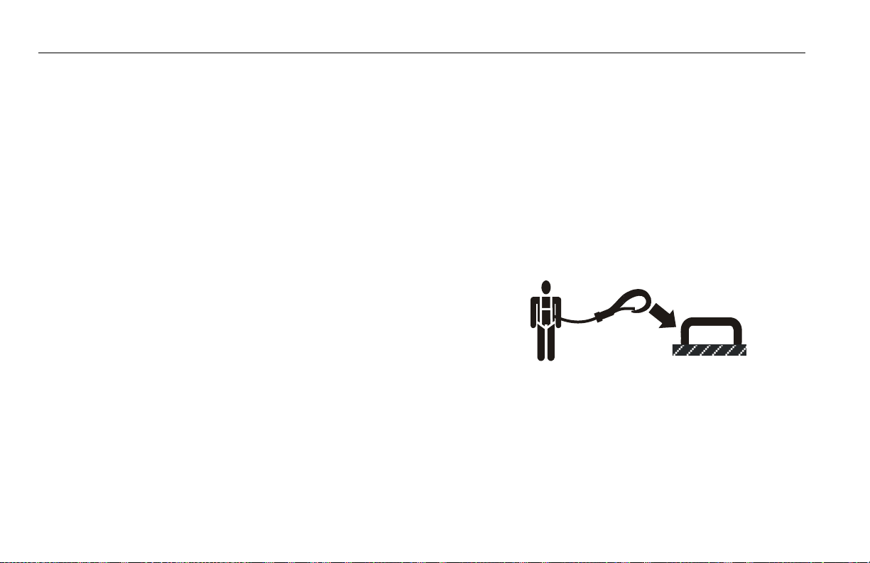
• During operation, occupants in the platform must wear a full
body harness with a lanyard attached to an authorized lanyard
anchorage point. Attach only one (1) lanyard per lanyard
anchorage point.
• Enter and exit only through gate area. Use extreme caution
when entering or leaving platform. Ensure that the platform
assembly is fully lowered. Face the machine when entering or
leaving the platform. Always maintain “three point contact”
with the machine, using two hands and one foot or two feet
and one hand at all times during entry and exit.
1-4 – JLG Lift – 3121670
Page 19
SECTION 1 - SAFETY PRECAUTIONS
• Before operating the machine, make sure all gates are closed
and fastened in their proper position.
• Keep both feet firmly positioned on the platform floor at all
times. Never position ladders, boxes, steps, planks, or similar
items on unit to provide additional reach for any purpose.
• Keep oil, mud, and slippery substances cleaned from footwear
and the platform floor.
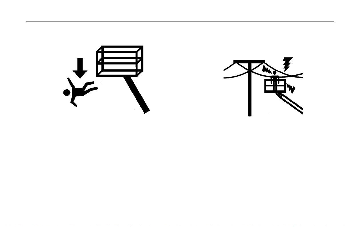
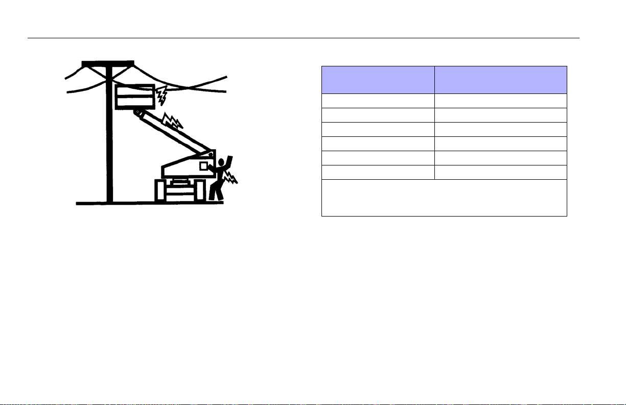
Electrocution Hazards
• This machine is not insulated and does not provide protection
from contact or proximity to electrical current.
3121670 – JLG Lift – 1-5
Page 20
SECTION 1 - SAFETY PRECAUTIONS
Table 1-1. Minimum Approach Distances (M.A.D.)
• Maintain distance from electrical lines, apparatus, or any energized (exposed or insulated) parts according to the Minimum
Approach Distance (MAD) as shown in Table 1-1.
• Allow for machine movement and electrical line swaying.
Voltage Range
(Phase to Phase)
0 to 50 KV 10 (3)
Over 50KV to 200 KV 15 (5)
Over 200 KV to 350 KV 20 (6)
Over 350 KV to 500 KV 25 (8)
Over 500 KV to 750 KV 35 (11)
Over 750 KV to 1000 KV 45 (14)
NOTE: This requirement shall apply except where
employer, local or governmental regulations are
more stringent.
• Maintain a clearance of at least 10 ft. (3m) between any part of
the machine and its occupants, their tools, and their equipment from any electrical line or apparatus carrying up to
50,000 volts. One foot additional clearance is required for
every additional 30,000 volts or less.
MINIMUM APPROACH DISTANCE
in Feet (Meters)
1-6 – JLG Lift – 3121670
Page 21
SECTION 1 - SAFETY PRECAUTIONS
• The minimum approach distance may be reduced if insulating
barriers are installed to prevent contact, and the barriers are
rated for the voltage of the line being guarded. These barriers
shall not be part of (or attached to) the machine. The minimum approach distance shall be reduced to a distance within
the designed working dimensions of the insulating barrier.
This determination shall be made by a qualified person in
accordance with the employer, local, or governmental requirements for work practices near energized equipment.
DO NOT MANEUVER MACHINE OR PERSONNEL INSIDE PROHIBITED ZONE (MAD).
ASSUME ALL ELECTRICAL PARTS AND WIRING ARE ENERGIZED UNLESS KNOWN OTHERWISE.
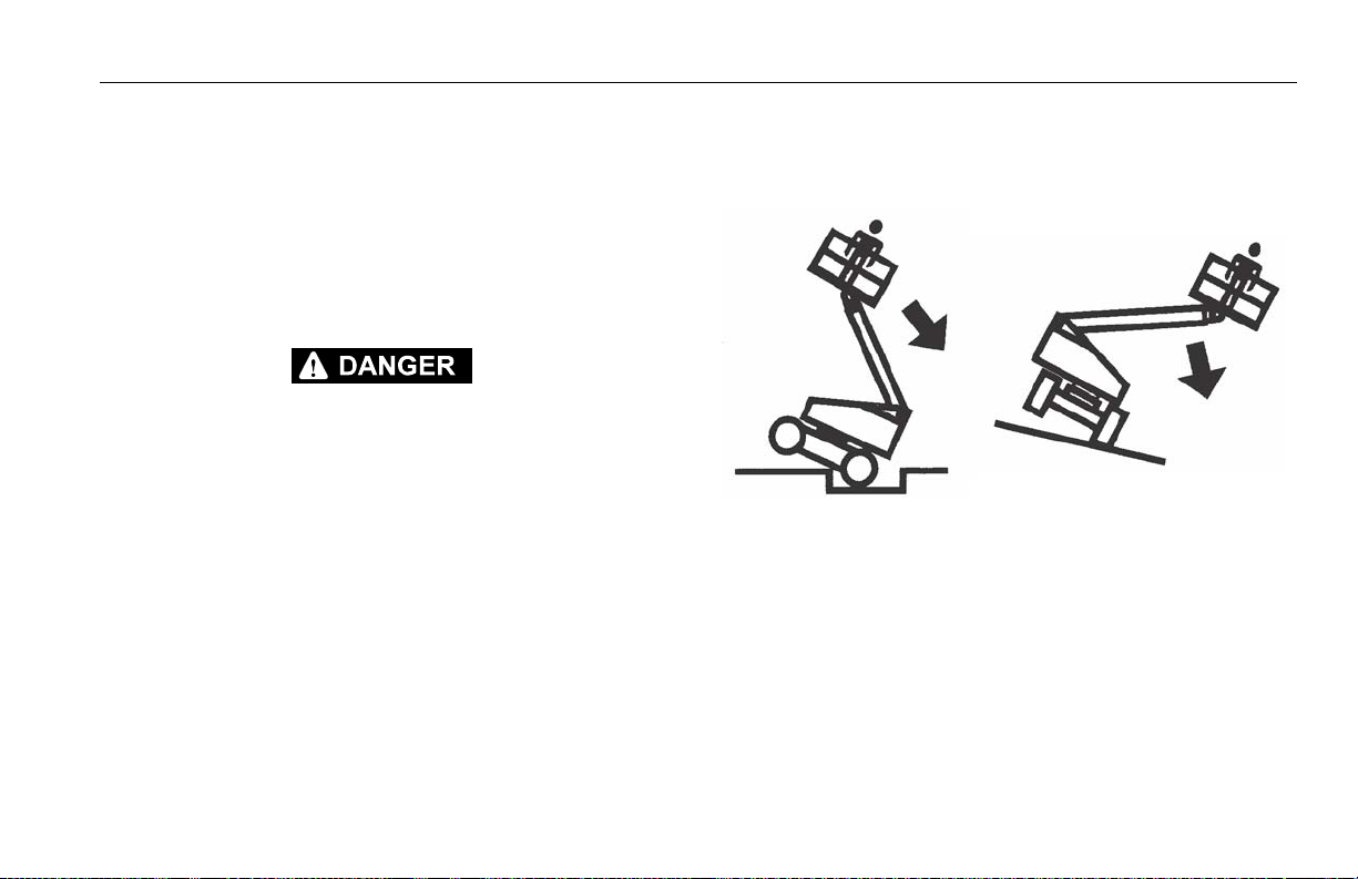
Tipping Hazards
• The user must be familiar with the surface before driving. Do
not exceed the allowable sideslope and grade while driving.
• Do not elevate platform or drive with platform elevated while
on or near a sloping, uneven, or soft surface. Ensure machine is
positioned on a firm, level and smooth surface before elevating platform or driving with the platform in the elevated position.
• Before driving on floors, bridges, trucks, and other surfaces,
check allowable capacity of the surfaces.
3121670 – JLG Lift – 1-7
Page 22

SECTION 1 - SAFETY PRECAUTIONS
• Never exceed the maximum work load as specified on the
platform. Keep all loads within the confines of the platform,
unless authorized by JLG.
• Keep the chassis of the machine a minimum of 2 ft. (0.6m)
from holes, bumps, drop-offs, obstructions, debris, concealed
holes, and other potential hazards at the ground level.
• Do not push or pull any object with the boom.
• Never attempt to use the machine as a crane. Do not tie-off
machine to any adjacent structure. Never attach wire, cable, or
any similar items to platform.
• If boom assembly or platform is in a position that one or more
wheels are off the ground, all persons must be removed before
attempting to stabilize the machine. Use cranes, forklift trucks,
or other appropriate equipment to stabilize machine.
• Do not operate the machine when wind conditions, including
gusts, may exceed 28 mph (12.5 m/s). Factors affecting wind
speed are; platform elevation, surrounding structures, local
weather events, and approaching storms. Refer to Table 1-2,
Beaufort scale (For Reference Only) or use other means to
monitor wind conditions.
• Wind speed can be significantly greater at height than at
ground level.
• Wind speed can change rapidly. Always consider approaching
weather events, the time required to lower the platform, and
methods to monitor current and potential wind conditions.
• Do not increase surface area of the platform or the load.
Increased areas exposed to wind will decrease stability.
• Do not increase the platform size with unauthorized modifications or attachments.
1-8 – JLG Lift – 3121670
Page 23
DO NOT OPERATE THE MACHINE WHEN WIND CONDITIONS EXCEED 28 MPH (12.5 M/
S).
Table 1-2. Beaufort Scale (For Reference Only)
SECTION 1 - SAFETY PRECAUTIONS
Beaufort
Number
0 0 0-0.2 Calm Calm. Smoke rises vertically
1 1-3 0.3-1.5 Light air Wind motion visible in smoke
2 4-7 1.6-3.3 Light breeze Wind felt on exposed skin. Leaves rustle
3 8-12 3.4-5.4 Gentle breeze Leaves and smaller twigs in constant motion
4 13-18 5.5-7.9 Moderate breeze Dust and loose paper raised. Small branches begin to move.
5 19-24 8.0-10.7 Fresh breeze Smaller trees sway.
6 25-31 10.8-13.8 Strong breeze Large branches in motion. Flags waving near horizontal. Umbrella use
7 32-38 13.9-17.1 Near Gale/Moderate Gale Whole trees in motion. Effort needed to walk against the wind.
8 39-46 17.2-20.7 Fresh Gale Twigs broken fro m trees. Cars veer on road.
9 47-54 20.8-24.4 Strong Gale Light structure damage.
Wind Speed
mph m/s
Description Land Conditions
becomes difficult.
3121670 – JLG Lift – 1-9
Page 24
SECTION 1 - SAFETY PRECAUTIONS
Crushing and Collision Hazards
• Approved head gear must be worn by all operating and
ground personnel.
• Check work area for clearances overhead, on sides, and bottom of platform when lifting or lowering platform, and driving.
• During operation, keep all body parts inside platform railing.
• Use the boom functions, not the drive function, to position the
platform close to obstacles.
• Always post a lookout when driving in areas where vision is
obstructed.
• Keep non-operating personnel at least 6 ft. (1.8m) away from
machine during all driving and swing operations.
• Under all travel conditions, the operator must limit travel
speed according to conditions of ground surface, congestion,
visibility, slope, location of personnel, and other factors which
may cause collision or injury to personnel.
• Be aware of stopping distances in all drive speeds. When driving in high speed, switch to low speed before stopping. Travel
grades in low speed only.
• Do not use high speed drive in restricted or close quarters or
when driving in reverse.
• Exercise extreme caution at all times to prevent obstacles from
striking or interfering with operating controls and persons in
the platform.
• Be sure that operators of other overhead and floor level
machines are aware of the aerial work platform’s presence. Disconnect power to overhead cranes.
• Warn personnel not to work, stand, or walk under a raised
boom or platform. Position barricades on floor if necessary.
1-10 – JLG Lift – 3121670
Page 25

SECTION 1 - SAFETY PRECAUTIONS
1.4 TOWING, LIFTING, AND HAULING
• Never allow personnel in platform while towing, lifting, or
hauling.
• This machine should not be towed, except in the event of
emergency, malfunction, power failure, or loading/unloading.
Refer to the Emergency Procedures section of this manual for
emergency towing procedures.
• Ensure boom is in the stowed position and the turntable
locked prior to towing, lifting or hauling. The platform must be
completely empty of tools.
• When lifting machine, lift only at designated areas of the
machine. Lift the unit with equipment of adequate capacity.
• Refer to the Machine Operation section of this manual for lifting information.
1.5 MAINTENANCE
This sub-section contains general safety precautions which must
be observed during maintenance of this machine. Additional precautions to be observed during machine maintenance are
inserted at the appropriate points in this manual and in the Service and Maintenance Manual. It is of utmost importance that
maintenance personnel pay strict attention to these precautions
to avoid possible injury to personnel or damage to the machine
or property. A maintenance program must be established by a
qualified person and must be followed to ensure that the
machine is safe.
Maintenance Hazards
• Shut off power to all controls and ensure that all moving parts
are secured from inadvertent motion prior to performing any
adjustments or repairs.
• Never work under an elevated platform until it has been fully
lowered to the full down position, if possible, or otherwise
supported and restrained from movement with appropriate
safety props, blocking, or overhead supports.
• DO NOT attempt to repair or tighten any hydraulic hoses or fittings while the machine is powered on or when the hydraulic
system is under pressure.
• Always relieve hydraulic pressure from all hydraulic circuits
before loosening or removing hydraulic components.
3121670 – JLG Lift – 1-11
Page 26
SECTION 1 - SAFETY PRECAUTIONS
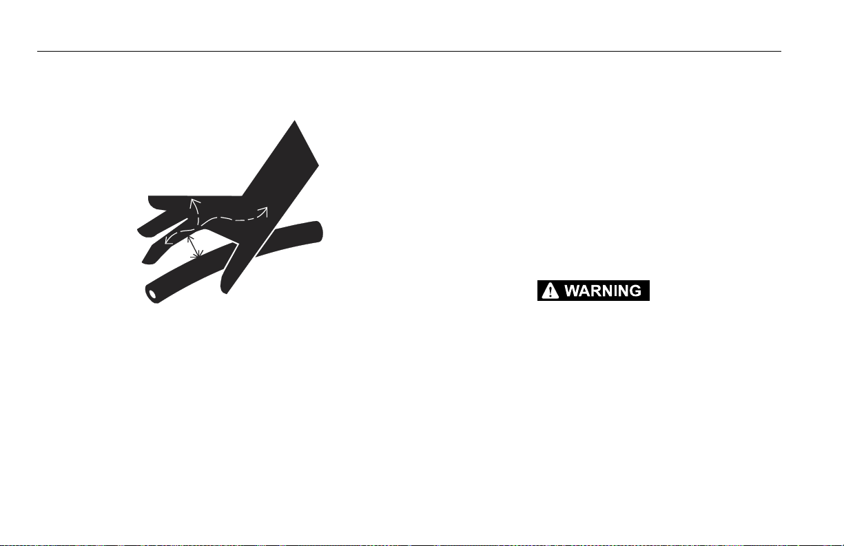
• DO NOT use your hand to check for leaks. Use a piece of cardboard or paper to search for leaks. Wear gloves to help protect
hands from spraying fluid.
• Ensure replacement parts or components are identical or
equivalent to original parts or components.
• Never attempt to move heavy parts without the aid of a
mechanical device. Do not allow heavy objects to rest in an
unstable position. Ensure adequate support is provided when
raising components of the machine.
• Do not use machine as a ground for welding.
• When performing welding or metal cutting operations, precautions must be taken to protect the chassis from direct
exposure to weld and metal cutting spatter.
• Do not refuel the machine with the engine running.
• Use only approved non-flammable cleaning solvents.
• Do not replace items critical to stability, such as batteries or
solid tires, with items of different weight or specification. Do
not modify unit in any way to affect stability.
• Refer to the Service and Maintenance Manual for the weights
of critical stability items.
MODIFICATION OR ALTERATION OF AN AERIAL WORK PLATFORM SHALL BE MADE
ONLY WITH PRIOR WRITTEN PERMISSION FROM THE MANUFACTURER.
1-12 – JLG Lift – 3121670
Page 27

Battery Hazards
SECTION 1 - SAFETY PRECAUTIONS
• Always disconnect batteries when servicing electrical components or when performing welding on the machine.
• Do not allow smoking, open flame, or sparks near battery during charging or servicing.
• Do not contact tools or other metal objects across the battery
terminals.
• Always wear hand, eye, and face protection when servicing
batteries. Ensure that battery acid does not come in contact
with skin or clothing.
BATTERY FLUID IS HIGHLY CORROSIVE. AVOID CONTACT WITH SKIN AND
CLOTHING AT ALL TIMES. IMMEDIATELY RINSE ANY CONTACTED AREA WITH
CLEAN WATER AND SEEK MEDICAL ATTENTION.
• Charge batteries only in a well ventilated area.
• Avoid overfilling the battery fluid level. Add distilled water to
batteries only after the batteries are fully charged.
3121670 – JLG Lift – 1-13
Page 28

SECTION 1 - SAFETY PRECAUTIONS
NOTES:
1-14 – JLG Lift – 3121670
Page 29

SECTION 2 - USER RESPONSIBILITIES, MACHINE PREPARATION, AND INSPECTION
SECTION 2. USER RESPONSIBILITIES, MACHINE PREPARATION, AND INSPECTION
2.1 PERSONNEL TRAINING
The aerial platform is a personnel handling device; so it is necessary that it be operated and maintained only by trained personnel.
Persons under the influence of drugs or alcohol or who are subject to seizures, dizziness or loss of physical control must not
operate this machine.
Operator Training
Operator training must cover:
1. Use and limitations of the controls in the platform and at the
ground, emergency controls and safety systems.
2. Control labels, instructions, and warnings on the machine.
3. Rules of the employer and government regulations.
4. Use of approved fall protection device.
5. Enough knowledge of the mechanical operation of the
machine to recognize a malfunction or potential malfunction.
6. The safest means to operate the machine where overhead
obstructions, other moving equipment, and obstacles,
depressions, holes, or drop-offs exist.
7. Means to avoid the hazards of unprotected electrical conductors.
8. Specific job requirements or machine application.
Training Supervision
Training must be done under the supervision of a qualified person in an open area free of obstructions until the trainee has
developed the ability to safely control and operate the machine.
Operator Responsibility
The operator must be instructed that he/she has the responsibility and authority to shut down the machine in case of a malfunction or other unsafe condition of either the machine or the job
site.
3121670 – JLG Lift – 2-1
Page 30

SECTION 2 - USER RESPONSIBILITIES, MACHINE PREPARATION, AND INSPECTION
2.2 PREPARATION, INSPECTION, AND MAINTENANCE
The following table covers the periodic machine inspections and
maintenance required by JLG Industries, Inc. Consult local regulations for further requirements for aerial work platforms. The frequency of inspections and maintenance must be increased as
necessary when the machine is used in a harsh or hostile environment, if the machine is used with increased frequency, or if the
machine is used in a severe manner.
JLG INDUSTRIES, INC. RECOGNIZES A FACTORY TRAINED SERVICE TECHNICIAN AS A
PERSON WHO HAS SUCCESSFULLY COMPLETED THE JLG SERVICE TRAINING SCHOOL
FOR THE SPECIFIC JLG PRODUCT MODEL.
2-2 – JLG Lift – 3121670
Page 31

SECTION 2 - USER RESPONSIBILITIES, MACHINE PREPARATION, AND INSPECTION
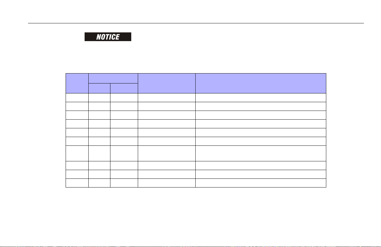
Table 2-1. Inspection and Maintenance Table
Type Frequenc y
Pre-Start Inspection Before using each day; or
whenever there’s an Operator change.
Pre-Delivery Inspection (See
Note)
Frequent Inspection
(See Note)
Annual Machine Inspection
(See Note)
Preventative Maintenance At intervals as specified in the Service and Maintenance
NOTE: Inspection forms are available from JLG. Use the Service and Maintenance Manual to perform inspections.
Before each sale, lease, or rental delivery. Owner, Dealer, or User Qualifie d JLG Mechanic Service and Maintenance Manual
In service for 3 months or 150 hours, whichever comes first;
or
Out of service for a period of mo re than 3 months; or
Purchase d used.
An n ua l ly , n o la t er t ha n 13 m on t hs f ro m th e da te o f p r i or
inspection.
Manual.
Primary
Responsibility
User or Operator User or Operator Operator and Safety Manual
Owner, Dealer, or User Qu alified JLG Mechanic Service and Maintenan ce Manual
Owner, Dealer, or User Factory Trained
Owner, Dealer, or User Qu alified JLG Mechanic Service and Maintenan ce Manual
Service
Qualification
Service Technician
(Recommended)
Reference
and applicable JLG inspection form
and applicable JLG inspection form
Service and Maintenance Manual
and applicable JLG inspection form
3121670 – JLG Lift – 2-3
Page 32

SECTION 2 - USER RESPONSIBILITIES, MACHINE PREPARATION, AND INSPECTION
Parent Metal Crack Weld Crack
Pre-Start Inspection
The Pre-Start Inspection should include each of the following:
1. Cleanliness – Check all surfaces for leakage (oil, fuel, or battery fluid) or foreign objects. Report any leakage to the
proper maintenance personnel.
2. Structure - Inspect the machine structure for dents, damage, weld or parent metal cracks or other discrepancies.
3. Decals and Placards – Check all for cleanliness and legibility. Make sure none of the decals and placards are missing.
Make sure all illegible decals and placards are cleaned or
replaced.
4. Operation and Safety Manuals – Make sure a copy of the
Operation and Safety Manual, AEM Safety Manual (ANSI
markets only), and ANSI Manual of Responsibilities (ANSI
markets only) is enclosed in the weather resistant storage
container.
5. “Walk-Around” Inspection – Refer to Figure 2-2.
6. Battery – Charge as required.
7. Fuel (Combustion Engine Powered Machines) – Add the
proper fuel as necessary.
8. Engine Oil Supply - Ensure the engine oil level is at the Full
mark on the dipstick and the filler cap is secure.
9. Hydraulic Oil – Check the hydraulic oil level. Ensure hydraulic oil is added as required.
10. Accessories/Attachments - Reference the Operator and
Safety Manual of each attachment or accessory installed
upon the machine for specific inspection, operation, and
maintenance instructions.
2-4 – JLG Lift – 3121670
Page 33

SECTION 2 - USER RESPONSIBILITIES, MACHINE PREPARATION, AND INSPECTION
11. Function Check – Once the “Walk-Around” Inspection is
complete, perform a functional check of all systems in an
area free of overhead and ground level obstructions. Refer to
Section 4 for more specific operating instructions.
IF THE MACHINE DOES NOT OPERATE PROPERLY, TURN OFF THE MACHINE IMMEDIATELY! REPORT THE PROBLEM TO THE PROPER MAINTENANCE PERSONNEL. DO NOT
OPERATE THE MACHINE UNTIL IT IS DECLARED SAFE FOR OPERATION.
Function Check
Perform the Function Check as follows:
1. From the ground control console with no load in the platform:
a. Check that all guards protecting the switches or locks
are in place;
b. Operate all functions and ensure proper operation;
c. Check auxiliary power and ensure proper operation;
d. Ensure that all machine functions are disabled when
the Emergency Stop Button is pushed in.
e. Ensure all boom functions stop when the function
enable switch is released.
2. From the platform control console:
a. Ensure that the control console is firmly secured in the
proper location;
b. Check that all guards protecting the switches or locks
are in place;
c. Operate all functions and ensure proper operation;
d. Ensure that all machine functions are disabled when
the Emergency Stop Button is pushed in.
e. Ensure that all machine functions stop when the foot-
switch is released.
3. With the platform in the stowed position:
a. Drive the machine on a grade, not to exceed the rated
gradeability, and stop to ensure the brakes hold;
b. Check that the tilt indicator is illuminated to ensure
proper operation.
4. Swing the boom over either of the rear tires and ensure that
the Drive Orientation indicator illuminates and that the
Drive Orientation Override switch must be used for the drive
function to operate.
3121670 – JLG Lift – 2-5
Page 34

SECTION 2 - USER RESPONSIBILITIES, MACHINE PREPARATION, AND INSPECTION
SkyGuard Function Test
From the Platform Console:
Test the SkyGuard feature by operating the telescope out functions and then activating the SkyGuard sensor. The telescope out
function will stop and the telescope in function will operate for a
short duration and the horn will sound until the SkyGuard sensor
and footswitch are disengaged.
NOTE: If equipped, ensure the blue beacon illuminates when SkyGuard
is activated.
Disengage the SkyGuard sensor, release controls, recycle the foot
switch, make sure normal operation is available.
If SkyGuard remains activated after function reversal or cutout,
depress and hold the SkyGuard Override Switch to allow normal
use of machine functions until the SkyGuard sensor is disengaged.
2-6 – JLG Lift – 3121670
Page 35

Figure 2-1. Basic Nomenclature
1. Platform
2. Platform Console
3. SkyGuard (If Equipped)
4. Cross Rail (If Equipped)
5. Fly Boom Se ction
6. Base Boom S ection
7. Front Drive/Steer Wheels
8. Rear Drive Wheels
9. Frame
10. Turntable
11. Oscillation Cylinder
12. Ground Console
OR
SECTION 2 - USER RESPONSIBILITIES, MACHINE PREPARATION, AND INSPECTION
3121670 – JLG Lift – 2-7
Page 36

SECTION 2 - USER RESPONSIBILITIES, MACHINE PREPARATION, AND INSPECTION
Figure 2-2. Daily Walk-Around Inspection - Sheet 1 of 3
2-8 – JLG Lift – 3121670
Page 37

SECTION 2 - USER RESPONSIBILITIES, MACHINE PREPARATION, AND INSPECTION
General
Begin the "Walk-Around Inspection" at Item 1, as noted on the
diagram. Continue checking each item in sequence for the conditions listed in the following checklist.
TO AVOID POSSIBLE INJURY, BE SURE MACHINE POWER IS OFF.
DO NOT OPERATE MACHINE UNTIL ALL MALFUNCTIONS HAVE BEEN CORRECTED.
INSPECTION NOTE: On all components, make sure there are no
loose or missing parts, that they are securely fastened, and no visible damage, leaks or excessive wear exists in addition to any other
criteria mentioned.
1. Platform Assembly and Gate - Footswitch works properly, not modified, disabled or blocked. Latch and hinges
in working condition.
2. Platform & Ground Control Consoles - Switches and
levers return to neutral, decals/placards secure and legible,
control markings legible.
3. Boom Sections/Turntable - See Inspection Note.
4. Swing Drive - No evidence of damage.
5. Wheel/Tire Assemblies - Properly secured, no missing lug
nuts. Inspect for worn tread, cuts, tears or other discrepancies. Inspect wheels for damage and corrosion.
6. Drive Motor, Brake, and Hub - No evidence of leakage.
7. Hood Assemblies - See Inspection Note.
8. All Hydraulic Cylinders - No visible damage; pivot pins
and hydraulic hoses undamaged, not leaking.
9. Turntable Bearing - Evidence of proper lubrication. No
evidence of loose bolts or looseness between bearing and
machine.
10. Tie Rod Ends and Steering Spindles - See Inspection
Note.
Figure 2-3. Daily Walk-Around Inspection - Sheet 2 of 3
3121670 – JLG Lift – 2-9
Page 38

SECTION 2 - USER RESPONSIBILITIES, MACHINE PREPARATION, AND INSPECTION
11. Hydraulic Pump - See Inspection Note.
12. Fuel Tank - See Inspection Note.
13. Hydraulic Reservoir - See Inspection Note.
14. Battery - Batteries have proper electrolyte level; cables
tight; see Inspection Note.
15. Platform Rotator - See Inspection Note.
16. SkyGuard (If Equipped) - See Inspection Note.
Figure 2-4. Daily Walk-Around Inspection - Sheet 3 of 3
2-10 – JLG Lift – 3121670
Page 39

SECTION 2 - USER RESPONSIBILITIES, MACHINE PREPARATION, AND INSPECTION
2.3 OSCILLATING AXLE LOCKOUT TEST (IF EQUIPPED)
LOCKOUT SYSTEM TEST MUST BE PERFORMED QUARTERLY, ANY TIME A SYSTEM COMPONENT IS REPLACED, OR WHEN IMPROPER SYSTEM OPERATION IS SUSPECTED.
NOTE: Ensure boom is fully retracted, lowered, and centered between
rear wheels prior to beginning lockout cylinder test.
1. Place a 6 inches (15.2 cm) high block with ascension ramp in
front of left front wheel.
2. From platform control console, start engine.
3. Place the Drive control lever to the forward position and
carefully drive machine up ascension ramp until left front
wheel is on top of block.
4. Carefully activate Telescope or Main Boom Lift control and
take the boom out of the transport position.
5. Place Drive control lever to Reverse and drive machine off of
block and ramp.
6. Have an assistant check to see that left front or right rear
wheel remains elevated in position off of ground.
7. Return boom to stowed position. When boom reaches center, stowed position, lockout cylinders should release and
allow wheel to rest on ground, it may be necessary to activate Drive to release cylinders.
8. Place the 6 inches (15.2 cm) high block with ascension ramp
in front of right front wheel.
9. Place Drive control lever to Forward and carefully drive
machine up ascension ramp until right front wheel is on top
of block.
10. Repeat steps 4 thru 7 to check the opposite side of the oscillating axle.
11. If lockout cylinders do not function properly, have qualified
personnel correct the malfunction prior to any further operation.
3121670 – JLG Lift – 2-11
Page 40

SECTION 2 - USER RESPONSIBILITIES, MACHINE PREPARATION, AND INSPECTION
NOTES:
2-12 – JLG Lift – 3121670
Page 41

SECTION 3 - MACHINE CONTROLS AND INDICATORS
SECTION 3. MACHINE CONTROLS AND INDICATORS
3.1 GENERAL
THE MANUFACTURER HAS NO DIRECT CONTROL OVER MACHINE APPLICATION AND
OPERATION. THE USER AND OPERATOR ARE RESPONSIBLE FOR CONFORMING WITH
GOOD SAFETY PRACTICES.
This section provides the necessary information needed to
understand control functions.
3.2 CONTROLS AND INDICATORS
NOTE: All machines are equipped with control consoles that use sym-
bols to indicate control functions. On ANSI machines refer to
decal located on the control box guard in front of the control box
or by the ground controls for these symbols and the corresponding functions.
NOTE: The indicator panels use different shaped symbols to alert the
operator to different types of operational situations that could
arise. The meaning of those symbols are explained below.
Indicates a potentially hazardous situation, which if
not corrected, could result in serious injury or death.
This indicator will be red.
Indicates an abnormal operating condition, which if
not corrected, may result in machine interruption or
damage. This indicator will be yellow.
Indicates important information regarding the operating condition, i.e. procedures essential for safe operation. This indicator will be green with the exception of
the capacity indicator which will be green or yellow
depending upon platform position.
3121670 – JLG Lift – 3-1
Page 42

SECTION 3 - MACHINE CONTROLS AND INDICATORS
2. Display Gauge
TO AVOID SERIOUS INJURY, DO NOT OPERATE MACHINE IF ANY CONTROL LEVERS OR
TOGGLE SWITCHES CONTROLLING PLATFORM MOVEMENT DO NOT RETURN TO THE
OFF POSITION WHEN RELEASED.
Ground Control Console
(See Figure 3-1., Figure 3-2., Figure 3-3., and Figure 3-4.
1. Indicator Panel
The Indicator Panel contains indicator lights that signal
problem conditions or functions operating during machine
operation.
NOTE: The Function Enable switch must be held down in
order to operate Main Boom Telescope, Swing,
Main Lift, Jib Lift, Platform Level Override, and
Platform Rotate functions.
Registers the amount of time the machine
has been in use, with engine running. The
hourmeter registers up to 16,500 hours and
cannot be reset.
3. Engine Start/ Auxiliary Power /Function Enable
To start the engine, the switch must be held
"UP" until the engine starts.
To use auxiliary power, the switch must be
held “DOWN” for duration of function use.
When the engine is running, the switch must
be held "DOWN" to enable all boom controls.
3-2 – JLG Lift – 3121670
Page 43

SECTION 3 - MACHINE CONTROLS AND INDICATORS
Figure 3-1. Ground Control Console - 400S
1. Indicator Panel
2. Display Gauge
3. Engine Start/Auxiliar y Power/
Fu n c ti o n E n ab l e
4. Platform/Ground Select
5. Platform Level
6. Platform Rotate
7. Not Used
8. Telescope
9. Power/Emergency Stop
10. Main Boom Lif t
11. Swing
12. Not Used
3121670 – JLG Lift – 3-3
Page 44

SECTION 3 - MACHINE CONTROLS AND INDICATORS
Figure 3-2. Ground Control Console - 400S w/MSSO (CE Only)
1. Indicator Panel
2. Display Gauge
3. Engine Start/Auxiliar y Power/
Fu n c ti o n E n ab l e
4. Platform/Ground Select
5. Platform Level
6. Platform Rotate
7. Not Used
8. Telescope
9. Power/Emergency Stop
10. Main Boom Lif t
11. Swing
12. Machine Safety System Override (MSSO)
3-4 – JLG Lift – 3121670
Page 45

SECTION 3 - MACHINE CONTROLS AND INDICATORS
Figure 3-3. Ground Control Console - 460SJ
1. Indicator Panel
2. Display Gauge
3. Engine Start/Auxiliary Power/
Fu n c ti o n E n ab l e
4. Platform/Ground Select
5. Platform Level
6. Platform Rotate
7. Jib Lift
8. Telescope
9. Power/Emergency Stop
10. Main Boom Lif t
11. Swing
12. Not Used
3121670 – JLG Lift – 3-5
Page 46

SECTION 3 - MACHINE CONTROLS AND INDICATORS
Figure 3-4. Ground Control Console - 460SJ w/MSSO (CE Only)
1. Indicator Panel
2. Display Gauge
3. Engine Start/Auxiliar y Power/
Fu n c ti o n E n ab l e
4. Platform/Ground Select
5. Platform Level
6. Platform Rotate
7. Jib Lift
8. Telescope
9. Power/Emergency Stop
10. Main Boom Lif t
11. Swing
12. Machine Safety System Override (MSSO)
3-6 – JLG Lift – 3121670
Page 47

SECTION 3 - MACHINE CONTROLS AND INDICATORS
NOTE: When the Platform/Ground Select Switch is in the center posi-
tion, power is shut off to the controls at both operating consoles.
Remove the key to prevent the controls from being actuated.
4. Platform/Ground Select Switch
The three position, key operated switch supplies power to the platform control console
when positioned to PLATFORM. With the
switch key turned to the GROUND position
only ground controls are operable.
ONLY USE THE PLATFORM LEVELING OVERRIDE FUNCTION FOR SLIGHT LEVELING OF
THE PLATFORM. INCORRECT USE COULD CAUSE THE LOAD/OCCUPANTS TO SHIFT OR
FALL. FAILURE TO DO SO COULD RESULT IN DEATH OR SERIOUS INJURY.
5. Platform Leveling Override
A three position switch allows the operator to
adjust the automatic self leveling system. This
switch is used to adjust platform level in situations such as ascending/descending a grade.
6. Platform Rotate
Provides rotation of the platform.
7. Jib Lift (If Equipped)
Provides raising and lowering of the jib.
3121670 – JLG Lift – 3-7
Page 48

SECTION 3 - MACHINE CONTROLS AND INDICATORS
8. Telescope Control
Provides extension and retraction of the boom.
WHEN THE MACHINE IS SHUT DOWN THE POWER/EMERGENCY STOP SWITCH MUST BE
POSITIONED TO THE OFF POSITION TO PREVENT DRAINING THE BATTERIES.
9. Power/Emergency Stop Switch
A two-position red mushroom shaped switch
supplies power to PLATFORM/GROUND
SELECT switch when pulled out (on). When
pushed in (off ), power is shut off to the PLATFORM/GROUND
SELECT switch.
10. Main Boom Lift
Provides raising/lowering of the main boom
when positioning up or down.
11. Swing
Provides 360 degrees continuous turntable
rotation.
12. Machine Safety System Override (MSSO) (CE
Only)
Provides emergency override of function
controls that are locked out in the event of
Load Sense System activation.
3-8 – JLG Lift – 3121670
Page 49

SECTION 3 - MACHINE CONTROLS AND INDICATORS
Ground Control Indicator Panel
(See Figure 3-5., Ground Control Indicator Panel)
1. Battery Malfunction Indicator
Indicates a problem in the battery or charging
circuit, and service is required.
2. High Engine Temperature Indicator
Indicates that engine coolant temperature is
abnormally high and service is required.
3. Low Engine Oil Pressure Indicator
Indicates that engine oil pressure is below normal and service is required.
4. Engine Oil Temperature Indicator (Deutz)
Indicates that the temperature of the engine
oil, which also serves as engine coolant, is
abnormally high and service is required.
5. Low Fuel Level Indicator
Indicates the fuel level is low. The Fuel
Reserve/Cut-Out System will shut the engine
down (or allow it start and run for an additional minute, depending upon machine setup) before the
fuel tank is emptied.
6. Glow Plug Indicator
Indicates the glow plugs are operating. After
turning on ignition, wait until light goes out
before cranking engine.
3121670 – JLG Lift – 3-9
Page 50

SECTION 3 - MACHINE CONTROLS AND INDICATORS
Figure 3-5. Ground Control Indicator Panel
1. Battery Malfunction
2. Low Engine Oil Pressure
3. High Engine Coolant Temperature
4. Engine Oil Temperature
5. System Distress
6. Low Fuel
7. Glow Plug
8. Platform Overload (If Equipped)
9. Drive and Steer Disable (If Equipped)
3-10 – JLG Lift – 3121670
Page 51

SECTION 3 - MACHINE CONTROLS AND INDICATORS
7. System Distress Indicator
The light indicates that the JLG Control System
has detected an abnormal condition and a
Diagnostic Trouble Code has been set in the
system memory. Refer to the Service Manual for instructions
concerning the trouble codes and trouble code retrieval.
The system distress indicator light will illuminate for 2-3 seconds when the key is positioned to the on position to act as
a self test.
8. Platform Overload Indicator (If Equipped)
Indicates the platform has been overloaded.
9. Drive and Steer Disable Indicator (If Equipped)
Indicates the Drive and Steer Disable function
has been activated.
3121670 – JLG Lift – 3-11
Page 52

SECTION 3 - MACHINE CONTROLS AND INDICATORS
Figure 3-6. Splash Screen
Ground Control Console Display Gauge
(See Figure 3-9., Ground Control Console Display Gauge)
The Display Gauge shows engine hours, fuel level (if applicable),
and Diagnostic Trouble Codes (DTCs) from both the JLG Control
System and the engine control system. During machine start up,
with no active DTCs in the control system, the splash screen will
show for 3 seconds and then switch to main screen. If there is an
active DTC while powering up the machine, the splash screen will
show for 3 seconds, and then launch the Diagnostics Screen. The
indicator lamp will light when there is an active DTC in the Fault
Log.
3-12 – JLG Lift – 3121670
Page 53

SECTION 3 - MACHINE CONTROLS AND INDICATORS
Figure 3-7. Diagnostic Screen
Figure 3-8. Engine Diagnostic Screen
The Diagnostic Screen will show active and inactive faults from
the JLG Control System on the screen. An asterisk (*) will be displayed to show active faults.
The Engine Diagnostics Screen will show SPN (Suspect Parameter
Number), FMI (Failure Mode Identifier), and Occurrence count
information. Engine SPN text is not scrollable. If there is more
than one engine trouble code, the operator must exit from the
Engine DTC Screen to see other SPN and FMI information.
3121670 – JLG Lift – 3-13
Page 54

SECTION 3 - MACHINE CONTROLS AND INDICATORS
Figure 3-9. Ground Control Console Display Gauge
INDICATOR LAMP
ENGINE HOURS
FUEL LEVEL
NAVIGATE FORWARD ARROW
NAVIGATION BUTTONS
NAVIGATE BACK ARROW
3-14 – JLG Lift – 3121670
Page 55

Platform Console
SECTION 3 - MACHINE CONTROLS AND INDICATORS
(See Figure 3-10., Platform Control Console)
TO AVOID SERIOUS INJURY, DO NOT OPERATE MACHINE IF ANY CONTROL LEVERS OR
TOGGLE SWITCHES CONTROLLING PLATFORM MOVEMENT DO NOT RETURN TO THE
OFF OR NEUTRAL POSITION WHEN RELEASED.
1. Drive Speed/Torque Select
The forward position gives maximum drive
speed. The back position gives maximum
torque for rough terrain and climbing
grades.
ONLY USE THE PLATFORM LEVELING OVERRIDE FUNCTION FOR SLIGHT LEVELING OF
THE PLATFORM. INCORRECT USE COULD CAUSE THE LOAD/OCCUPANTS TO SHIFT OR
FALL. FAILURE TO DO SO COULD RESULT IN DEATH OR SERIOUS INJURY.
2. Platform Leveling Override
A three position switch allows the operator to
adjust the automatic self leveling system. This
switch is used to adjust platform level in situations such as ascending/descending a grade.
3. Fuel Select (Dual Fuel Engine Only) (If
Equipped)
Moving the switch to the appropriate position
selects gasoline or liquid propane fuel.
4. Horn
A push-type HORN switch supplies electrical
power to an audible warning device when pressed.
3121670 – JLG Lift – 3-15
Page 56

SECTION 3 - MACHINE CONTROLS AND INDICATORS
1. Drive Speed/Torque Select
2. Platform Leveling Override
3. Fuel Select (I f Equipped)
4. Horn
5. Power/Emergency Stop
6. Start/Auxiliary Power
7. Capacity Se lect
8. Drive Orientation Override
9. Drive/Steer
10. Telescope
11. Lights (If Equipped)
12. Jib Lift (If Equipped)
13. Soft Touch/SkyGuard Override (If Equipped)
14. Soft Touch/SkyGuard Indicator (If Equipped)
15. Platform Rotate
16. Function Speed Control
17. Main Lift/Swing Controller
Figure 3-10. Platform Control Console
3-16 – JLG Lift – 3121670
Page 57

SECTION 3 - MACHINE CONTROLS AND INDICATORS
5. Power/Emergency Stop Switch
A two-position red mushroom shaped switch
furnishes power to PLATFORM Controls when
pulled out (on). When pushed in (off ), power is
shut off to the platform functions.
6. Start/Auxiliary Power
When pushed forward, the switch energizes the
starter motor to start the engine.
The Auxiliary Power control switch energizes
the electrically operated hydraulic pump.
(Switch must be held ON for duration of auxiliary pump use.)
The auxiliary pump functions to provide sufficient oil flow to
operate the basic machine functions should the main pump
or engine fail. The auxiliary pump will operate main boom
lift, main telescope, jib (if equipped) and swing.
7. Capacity Select
This switch allows the operator to select
between an operating envelope with a 600 lb.
(272 kg for ANSI markets and 270 kg for CE and
Australia markets) capacity restriction or a 1000
lb. (454 kg for ANSI markets and 450 kg for CE
and Australia markets) capacity restriction.
8. Drive Orientation Override
When the boom is swung over the rear tires
or further in either direction, the Drive Orientation indicator will illuminate when the drive
function is selected. Push and release the
switch, and within 3 seconds move the Drive/Steer control
to activate drive or steer. Before driving, locate the black/
white orientation arrows on both the chassis and the platform controls. Move the drive controls in a direction matching the directional arrows for the intended direction of
travel.
3121670 – JLG Lift – 3-17
Page 58

SECTION 3 - MACHINE CONTROLS AND INDICATORS
NOTE: To operate the Drive joystick, pull up on the lock-
ing ring below the handle.
NOTE: The Drive joystick is spring loaded and will auto-
matically return to neutral (off) position when
released.
9. Drive/Steer
Push forward to drive forward,
pull back to drive in reverse.
Steering is accomplished via a
thumb-activated rocker switch on
the end of the steer handle.
10. Telescope
Provides extension and retraction of the main
boom.
11. Lights (If Equipped)
This switch operates the chassis lights if
the machine is so equipped.
12. Jib Lift (If Equipped)
Provides for raising or lowering of the jib by
positioning up/down.
3-18 – JLG Lift – 3121670
Page 59

SECTION 3 - MACHINE CONTROLS AND INDICATORS
13. Soft Touch/SkyGuard Override Switch (If equipped)
The machine can be equipped with one of three options. It
may have Soft Touch, SkyGuard, or both Soft Touch and SkyGuard.
If equipped with Soft Touch, the switch
enables the functions that were cut out
by the Soft Touch system to operate
again at creep speed, allowing the
operator to move the platform away from the obstacle that
caused the shutdown situation.
If equipped with SkyGuard, the switch
enables functions cut out by the Skyguard system to be operated again,
allowing the operator to resume use of
machine functions.
If equipped with both Soft Touch and
SkyGuard, the switch operates like
described above and allows the operator to override the system that has
experienced a cutout situation.
14. Soft Touch/SkyGuard Indicator (If Equipped)
Indicates the Soft Touch bumper is against an object or the
SkyGuard sensor has been activated. All controls are cut out
until the override button is pushed. For Soft Touch, controls
are then active in the Creep Mode or for SkyGuard, controls
will work normally.
When Soft Touch is active, the indicator will be on continuously and the alarm will sound. When SkyGuard is active, the
indicator will flash, and the horn will sound continuously.
15. Platform Rotate
Provides rotation of the platform when positioned to the right or left.
16. Function Speed Control
This control affects the speed of telescope
and jib lift (if equipped). Turning the knob
all the way counterclockwise until it clicks
puts drive and swing into creep mode.
3121670 – JLG Lift – 3-19
Page 60

SECTION 3 - MACHINE CONTROLS AND INDICATORS
NOTE: To operate the Main Boom Lift/Swing joystick,
pull up on the locking ring below the handle.
NOTE: The Main Boom Lift/Swing joystick is spring loaded and will
automatically return to neutral (off) position when released.
17. Main Lift/Swing Controller
Provides main lift and swing. Push forward to lift up, pull backward to boom
down. Move right to swing right, move
left to swing left. Moving the joystick
activates switches to provide the functions selected.
3-20 – JLG Lift – 3121670
Page 61

SECTION 3 - MACHINE CONTROLS AND INDICATORS
Platform Control Indicator Panel
(See Figure 3-11., Platform Control Indicator Panel)
NOTE: The indicator lights will illuminate for approximately 1 second
when the key is positioned to the on position to act as a self test.
1. AC Generator (If Equipped)
Indicates the generator is in operation.
2. Platform Overload Indicator (If Equipped)
Indicates the platform has been overloaded.
3. Capacity Indicator
Indicates the maximum platform capacity for
the current position of the platform. Restricted
capacities are permitted at restricted platform
positions (shorter boom lengths and higher
boom angles).
NOTE: Refer to the capacity decals on the machine for restricted and
unrestricted platform capacities.
3121670 – JLG Lift – 3-21
Page 62

SECTION 3 - MACHINE CONTROLS AND INDICATORS
1. AC Generator (If Equipped)
2. Platform Overload (If Equipped)
3. Capacity Indicator
4. Tilt
5. Glow Plug/Wait to Start
6. Enable/Footswitch
7. Fuel Level
8. Creep
9. System Distress
10. Drive Orientation
Figure 3-11. Platform Control Indicator Panel
3-22 – JLG Lift – 3121670
Page 63

SECTION 3 - MACHINE CONTROLS AND INDICATORS
Tilt Angle Market
5° All Markets
4. Tilt Alarm Warning Light and Alarm
This red illuminator indicates that the chassis is
on a slope. An alarm will also sound when the
chassis is on an excessive slope and the boom
is out of transport position. If lit when boom is out of transport position, lower to below horizontal then reposition
machine so that it is level before continuing operation. If the
boom is above horizontal and the machine is on a slope, the
tilt alarm warning light will illuminate and an alarm will
sound and CREEP is automatically activated.
IF TILT WARNING LIGHT IS ILLUMINATED WHEN BOOM IS RAISED OR EXTENDED,
RETRACT AND LOWER TO BELOW HORIZONTAL THEN REPOSITION MACHINE SO THAT
IT IS LEVEL BEFORE EXTENDING BOOM OR RAISING BOOM ABOVE HORIZONTAL.
5. Glow Plug/Wait to Start Indicator
Indicates the glow plugs are operating. After
turning on ignition, wait until light goes out
before starting engine.
6. Enable Indicator/Footswitch
To operate any function, the footswitch must
be depressed and the function selected within
seven seconds. The enable indicator shows
that the controls are enabled. If a function is not selected
within seven seconds, or if a seven second lapse between
ending one function and beginning the next function, the
enable light will go out and the footswitch must be released
and depressed again to enable the controls.
Releasing the footswitch removes power from all controls
and applies the drive brakes.
TO AVOID SERIOUS INJURY, DO NOT REMOVE, MODIFY OR DISABLE THE FOOTSWITCH
BY BLOCKING OR ANY OTHER MEANS.
FOOTSWITCH MUST BE ADJUSTED IF FUNCTIONS ACTIVATE WHEN SWITCH ONLY
OPERATES WITHIN LAST 1/4" OF TRAVEL, TOP OR BOTTOM.
3121670 – JLG Lift – 3-23
Page 64

SECTION 3 - MACHINE CONTROLS AND INDICATORS
Figure 3-12. Fuel Level Indicator
7. Fuel Level Indicator
Indicates the level of fuel in the tank.
8. Creep Speed Indicator
When the Function Speed Control is turned to
the creep position, the indicator acts as a
reminder that all functions are set to the slowest speed. The light will be on continuously if the operator
selects creep speed or if the control system puts the
machine into creep speed. In addition, if the control system
puts one or more individual functions in creep speed, the
indicator flashes when that function is selected.
9. System Distress Indicator
The light indicates that the JLG Control System
has detected an abnormal condition and a
Diagnostic Trouble Code has been set in the
system memory. Refer to the Service Manual for instructions
concerning the trouble codes and trouble code retrieval.
10. Drive Orientation Indicator
When the boom is swung beyond the rear
drive tires or further in either direction, the
Drive Orientation indicator will illuminate
when the drive function is selected. This is a signal for the
operator to verify that the drive control is being operated in
the proper direction (i.e. controls reversed situations).
3-24 – JLG Lift – 3121670
Page 65

SECTION 4. MACHINE OPERATION
SECTION 4 - MACHINE OPERATION
4.1 DESCRIPTION
This machine is a self-propelled hydraulic personnel lift equipped
with a work platform on the end of an elevating and rotating
boom.
The primary operator control console is in the platform. From this
control console, the operator can drive and steer the machine in
both forward and reverse directions. The operator can raise or
lower the boom or swing the boom to the left or right. Standard
boom swing is 360 degree continuous. The machine has a
Ground Control Console which will override the Platform Control
Console. Ground Controls operate all functions except drive and
steer and are to be used in an emergency to lower the platform to
the ground should the operator in the platform be unable to do
so.
3121670 – JLG Lift – 4-1
Page 66

SECTION 4 - MACHINE OPERATION
4.2 BOOM OPERATING CHARACTERISTICS AND LIMITATIONS
Capacities
Raising boom above horizontal with or without any load in platform, is based on the following criteria:
1. Machine is positioned on a smooth, firm and level surface.
2. Load is within manufacturers rated design capacity.
3. All machine systems are functioning properly.
4. Machine is as originally equipped from JLG.
Stability
Machine stability is based on two (2) conditions which are called
FORWARD and BACKWARD stability. The machine’s position of
least FORWARD stability is shown in Figure 4-1., and its position
of least BACKWARD stability is shown in Figure 4-2.
TO AVOID FORWARD OR BACKWARD TIPPING, DO NOT OVERLOAD MACHINE OR OPERATE THE MACHINE ON AN OUT-OF-LEVEL SURFACE.
4.3 ENGINE OPERATION
NOTE: Initial starting should always be per-
formed from the Ground Control console.
Starting Procedure
IF ENGINE FAILS TO START PROMPTLY, DO NOT CRANK FOR AN EXTENDED TIME.
SHOULD ENGINE FAIL TO START AGAIN, ALLOW STARTER TO “COOL OFF” FOR 2-3 MINUTES. IF ENGINE FAILS AFTER SEVERAL ATTEMPTS, REFER TO ENGINE MAINTENANCE
MANUAL.
NOTE: Diesel engines only: After turning on ignition,
operator must wait until glow plug indicator light
goes out before cranking engine.
4-2 – JLG Lift – 3121670
Page 67

SECTION 4 - MACHINE OPERATION
1. Turn key of Platform/Ground Select switch to
Ground.
2. Pull the Power/Emergency Stop switch to On.
3. Push the Engine Start switch until engine starts.
ALLOW ENGINE TO WARM-UP FOR A FEW MINUTES AT LOW SPEED BEFORE APPLYING
ANY LOAD.
4. After engine has had sufficient time to warm
up, push in the Power/Emergency Stop switch
and shut engine off.
5. Turn Platform/Ground Select switch to Platform.
6. Pull out the Ground Console Power/Emergency Stop switch to provide power to the
platform controls.
7. From Platform, pull Power/Emergency Stop
switch out.
8. Push the Engine Start switch until engine starts.
NOTE: Footswitch must be in released (up) position before starter will
operate. If starter operates with footswitch in the depressed position, DO NOT OPERATE MACHINE.
3121670 – JLG Lift – 4-3
Page 68

SECTION 4 - MACHINE OPERATION
Shutdown Procedure
IF AN ENGINE MALFUNCTION CAUSES AN UNSCHEDULED SHUTDOWN, DETERMINE
THE CAUSE AND CORRECT IT BEFORE RESTARTING THE ENGINE.
1. Remove all load and allow engine to operate at low speed
for 3-5 minutes; this allows further reduction of internal
engine temperature.
2. Push Power/Emergency Stop switch in.
3. Turn Platform/Ground Select switch to Off.
Refer to Engine Manufacturer’s manual for detailed
information.
Fuel Reserve / Shut-Off System (Diesel Engines Only)
The Fuel Shutoff System senses when the fuel level is getting low
and automatically shuts the engine down before the fuel tank is
emptied.
Depending upon machine setup, the machine will either keep
the engine shut down until the fuel tank is refilled or the operator
will be able to restart and run the engine for an additional minute. After 1 minute, the engine will shut off for a second time and
the machine will return to the engine shutdown mode until the
fuel tank is refilled.
4-4 – JLG Lift – 3121670
Page 69

SECTION 4 - MACHINE OPERATION
Figure 4-1. Position of Least Forward Stability
JIB
HORIZONTAL
BOOM
FULLY EXTENDED
MACHINE WILL "TIP OVER" IN THIS
DIRECTION IF OVERLOADED OR
OPERATED ON AN
OUT-OF-LEVEL SURFACE
3121670 – JLG Lift – 4-5
Page 70

SECTION 4 - MACHINE OPERATION
Figure 4-2. Position of Least Backward Stability
JIB
FULLY ELEVATED
MAIN BOOM FULLY ELEVATED
AND FULLY RETRACTED
MACHINE WILL "TIP OVER" IN THIS
DIRECTION IF OVERLOADED OR
OPERATED ON AN
OUT-OF-LEVEL SURFACE
PLATFORM ROTATED
90 DEGREES
.
4-6 – JLG Lift – 3121670
Page 71

4.4 TRAVELING (DRIVING)
SECTION 4 - MACHINE OPERATION
See Figure 4-3., Grade and Side Slopes
NOTE: Refer to the Operating Specifications table for Gradeability and
Sideslope ratings.
All ratings for Gradeability and Sideslope are based upon the
machine’s boom being in the stowed position, fully lowered, and
retracted.
Traveling is limited by two factors:
1. Gradeability, which is the percent of grade of the incline the
machine can climb.
2. Sideslope, which is the angle of the slope the machine can
be driven across.
DO NOT DRIVE WITH BOOM OUT OF TRANSPORT MODE EXCEPT ON A SMOOTH, FIRM
AND LEVEL SURFACE.
TO AVOID LOSS OF TRAVEL CONTROL OR “TIP OVER”, DO NOT DRIVE MACHINE ON
GRADES EXCEEDING THOSE SPECIFIED IN THE OPERATING SPECIFICATIONS SECTION
OF THIS MANUAL.
DO NOT DRIVE ON SIDESLOPES WHICH EXCEED 5 DEGREES.
USE EXTREME CAUTION WHEN DRIVING IN REVERSE AND AT ALL TIMES WHEN THE
PLATFORM IS ELEVATED.
BEFORE DRIVING, LOCATE THE BLACK/WHITE ORIENTATION ARROWS ON BOTH THE
CHASSIS AND THE PLATFORM CONTROLS. MOVE THE DRIVE CONTROLS IN A DIRECTION MATCHING THE DIRECTIONAL ARROWS FOR THE INTENDED DIRECTION OF
TRAVEL
3121670 – JLG Lift – 4-7
Page 72

SECTION 4 - MACHINE OPERATION
Figure 4-3. Grade and Side Slopes
4-8 – JLG Lift – 3121670
Page 73

SECTION 4 - MACHINE OPERATION
Traveling Forward and Reverse
1. At Platform Controls, pull out Emergency Stop
switch, start the engine, and activate footswitch.
2. Position Drive controller to FORWARD or REVERSE as desired.
This machine is equipped with a Drive Orientation Indicator. The
yellow light on the platform control console indicates that the
boom is swung beyond the rear drive tires and the machine may
Drive/Steer in the opposite direction from the movement of the
controls. If the indicator is illuminated, operate the Drive function
in the following manner:
1. Match the black and
white direction arrows
on both platform control console and the
chassis to determine
the direction the
machine will travel.
2. Push and release the Drive Orientation Override switch. Within 3 seconds, slowly move the
Drive control toward the arrow matching the
intended direction of machine travel. The indicator light will flash during the 3 second interval until the drive function is selected.
3121670 – JLG Lift – 4-9
Page 74

SECTION 4 - MACHINE OPERATION
Figure 4-4. Traveling on a Grade
Traveling on a Grade
When traveling a grade, maximum braking and traction are obtained
with the boom stowed, in position over the rear (drive) axle, and in
line with the direction of travel. Drive the machine forward when
climbing a grade, and in reverse when descending a grade. Do not
exceed the machine's maximum rated gradeability.
IF THE BOOM IS OVER THE FRONT (STEER) AXLE, DIRECTION OF STEER AND DRIVE
MOVEMENT WILL BE OPPOSITE FROM THE MOVEMENT OF THE CONTROLS.
4.5 STEERING
Position thumb switch on Drive/Steer controller to
Right for steering right, or to Left for steering left.
4.6 PLATFORM
Platform Level Adjustment
ONLY USE THE PLATFORM LEVELING OVERRIDE FUNCTION FOR SLIGHT LEVELING OF
THE PLATFORM. INCORRECT USE COULD CAUSE THE LOAD/OCCUPANTS TO SHIFT OR
FALL. FAILURE TO DO SO COULD RESULT IN DEATH OR SERIOUS INJURY.
To Level Up or Down - Position the Platform/Level
control switch Up or Down and hold until the platform is level.
Platform Rotation
To rotate the platform to the left or right, use the
Platform Rotate control switch to select the direction and hold until desired position is reached.
4-10 – JLG Lift – 3121670
Page 75

4.7 BOOM
A RED TILT WARNING LIGHT IS LOCATED ON THE CONTROL CONSOLE WHICH LIGHTS
WHEN THE CHASSIS IS ON AN EXCESSIVE SLOPE. DO NOT SWING OR RAISE BOOM
ABOVE HORIZONTAL WHEN LIGHT IS LIT.
SECTION 4 - MACHINE OPERATION
TO AVOID A COLLISION AND INJURY IF PLATFORM DOES NOT STOP WHEN A CONTROL
SWITCH OR LEVER IS RELEASED, REMOVE FOOT FROM FOOTSWITCH OR USE EMERGENCY STOP SWITCH TO STOP THE MACHINE.
Swinging the Boom
DO NOT DEPEND ON TILT ALARM AS A LEVEL INDICATOR FOR THE CHASSIS. TILT
ALARM INDICATES CHASSIS IS ON AN EXCESSIVE SLOPE (5 DEGREES OR GREATER).
CHASSIS MUST BE LEVEL BEFORE SWINGING, OR RAISING BOOM ABOVE HORIZONTAL
OR DRIVING WITH THE BOOM ELEVATED.
TO AVOID TIP OVER IF RED TILT WARNING LIGHT LIGHTS WHEN BOOM IS RAISED
ABOVE HORIZONTAL, LOWER PLATFORM TO GROUND LEVEL. THEN REPOSITION
MACHINE SO THAT CHASSIS IS LEVEL BEFORE RAISING BOOM.
TRAVELING WITH BOOM BELOW HORIZONTAL IS PERMITTED ON GRADES AND SIDE
SLOPES SPECIFIED IN THE OPERATING SPECIFICATIONS SECTION OF THIS MANUAL.
TO AVOID SERIOUS INJURY, DO NOT OPERATE MACHINERY IF ANY CONTROL LEVER OR
TOGGLE SWITCH CONTROLLING PLATFORM MOVEMENT DOES NOT RETURN TO THE
‘OFF’ OR NEUTRAL POSITION WHEN RELEASED.
To swing boom, use Swing control switch to select
Right or Left direction.
Raising and Lowering the Main Boom
To raise or lower the Main Boom, use Main Boom Lift
controller to select UP or DOWN movement.
Telescoping the Main Boom
To extend or retract the main boom, use the Main
Telescope Control Switch to select IN or OUT movement.
3121670 – JLG Lift – 4-11
Page 76

SECTION 4 - MACHINE OPERATION
4.8 FUNCTION SPEED CONTROL
This control affects the speed of telescope and
jib lift. Turning the knob all the way counterclockwise until it clicks puts drive, main lift, platform rotate, and swing into creep mode.
4.9 MACHINE SAFETY SYSTEM OVERRIDE (MSSO)(CE ONLY)
The Machine Safety System Override (MSSO) is
used to override function controls for Emergency
Platform Retrieval only. Refer to Section 5.5,
Machine Safety System Override (MSSO)(CE
Only)for operating procedures.
4-12 – JLG Lift – 3121670
Page 77

SECTION 4 - MACHINE OPERATION
4.10 SKYGUARD OPERATION
Skyguard is used to provide enhanced control panel protection.
When the SkyGuard sensor is activated, functions that were in
Table 4-1. Skyguard Function Table
Main
Main
Lift
RCRRRC*RRRC C CC
R = Indicates Reversal is Activated
C = Indicates Cutout is Activated
* Disregard when boom is in line and driving forward with or without steering and no other functions active.
Note: When Soft Touch is enabled with SkyGuard all functions are cut out only.
Tel e
In
Main
Tel e
Out
Swing
Drive
Forw ard
DOS
Enabled
Drive
Reverse
DOS
Not
Enabled
use at the time of actuation will reverse or cutout. The table
below outlines these functions.
Towe r
Towe r
Lift
Up
Lift
Down
Platform
Level
Platform
Rotate
Jib
Lift
3121670 – JLG Lift – 4-13
Page 78

SECTION 4 - MACHINE OPERATION
4.11 SHUT DOWN AND PARK
Shut Down and Park
The procedures to shut down and park the machine are as follows:
1. Drive machine to a reasonably well protected area.
2. Ensure boom is lowered over rear drive axle.
3. Shut down Emergency Stop at Platform Controls.
4. Shut down Emergency Stop at Ground Controls. Position
Platform/Ground Select switch to center OFF.
5. If necessary, cover Platform Controls to protect instruction
placards, warning decals, and operating controls from hostile environment.
4.12 LIFTING AND TIE DOWN
(See Figure 4-5.)
Lifting
1. Refer to the Serial Number Plate, refer to the Specifications
section of this manual, or weigh the individual unit to find
out the Gross Vehicle Weight.
2. Place the boom in the stowed position.
3. Remove all loose items from the machine.
4. Properly adjust the rigging to prevent damage to the
machine and so the machine remains level.
4-14 – JLG Lift – 3121670
Page 79

Tie Down
WHEN TRANSPORTING THE MACHINE IN THE STOWED POSITION, THE BOOM MUST BE
FULLY LOWERED INTO THE BOOM REST.
1. Place the boom in the stowed position or storage position.
2. Remove all loose items from the machine.
3. Secure the chassis and the platform using straps or chains of
adequate strength.
SECTION 4 - MACHINE OPERATION
3121670 – JLG Lift – 4-15
Page 80

SECTION 4 - MACHINE OPERATION
Figure 4-5. Lifting and Tie Down Chart
4-16 – JLG Lift – 3121670
Page 81

SECTION 4 - MACHINE OPERATION
Figure 4-6. Decal Location Sheet 1 of 7
3121670 – JLG Lift – 4-17
Page 82

SECTION 4 - MACHINE OPERATION
Figure 4-7. Decal Location Sheet 2 of 7
4-18 – JLG Lift – 3121670
Page 83

SECTION 4 - MACHINE OPERATION
Figure 4-8. Decal Location Sheet 3 of 7
3121670 – JLG Lift – 4-19
Page 84

SECTION 4 - MACHINE OPERATION
Figure 4-9. Decal Location Sheet 4 of 7
4-20 – JLG Lift – 3121670
Page 85

SECTION 4 - MACHINE OPERATION
Figure 4-10. Decal Location Sheet 5 of 7
3121670 – JLG Lift – 4-21
Page 86

SECTION 4 - MACHINE OPERATION
Figure 4-11. Decal Location Sheet 6 of 7
4-22 – JLG Lift – 3121670
Page 87

SECTION 4 - MACHINE OPERATION
Figure 4-12. Decal Location Sheet 7 of 7
3121670 – JLG Lift – 4-23
Page 88

SECTION 4 - MACHINE OPERATION
Table 4-2. Decal Legend - 400S
Item # ANSI
1001171366-D
1 1703797 1703926 1703927 1703923 1703924 1703925 1703928 1705921
2 1703798 1703932 1703933 1703929 1703930 1703931 1703934 1705822
3 1703805 1703938 1703939 1703935 1703936 1703937 1703940 1705961
4 1703804 1703950 1703951 1703947 1703948 1703949 1703952 1701518
5 1001173262 1001173262 1001173262 1001173262 1001173262 1001173262 1001173262 - 6 1001174313 1001174313 1001174313 1001174313 1001174313 1001174313 1001174313 - 7- -- -- -- -- -- -- -- 8- -- -- -- -- -- -- -- -
9- -- -- -- -- -- -- -- 10- -- -- -- -- -- -- -- 11 1702868 - - - - 1704001 1704000 - - 1704002 - 12 1704277 1704277 1704277 1704277 1704277 1704277 1704277 1704277
13 1001171335 1001171341 1001171345 1001171349 1001171351 1001171355 1001171359 1001185237
14 1001171336 1001171342 1001171346 1001171350 1001171352 1001171356 1001171360 1001185237
15 3251813 - - - - 3251813 3251813 - - 3251813 1001204510
16 1701504 1701504 1701504 1701504 1701504 17701504 1701504 1701504
17 1702631 1702631 1702631 1702361 1702631 1702631 1702631 1702631
Japan
1001171370-D
Korea
1001171372-D
Spanish
1001171374-D
French
1001171376-D
Chinese
1001171378-D
Port uguese /
Spanish
1001171380-D
CE
1001171369-G
4-24 – JLG Lift – 3121670
Page 89

Table 4-2. Decal Legend - 400S
SECTION 4 - MACHINE OPERATION
Item # ANSI
1001171366-D
18 1001131269 - - - - - - 1001131269 - - - - - 19 1706948 1706948 1706948 1706948 1706948 1706948 1706948 - 20 1701509 1701509 1701509 1701509 1701509 1701509 1701509 1701509
21 1702300 1702300 1702300 1702300 1702300 1702300 1702300 1702300
22 1701500 1701500 1701500 1701500 1701500 1701500 1701500 1701500
23 1701529 1701529 1701529 1701529 1701529 1701529 1701529 1701529
24 3251243 - - - - 3251243 3251243 - - 3251243 - 25- -- -- -- -- -- -- -- 26- -- -- -- -- -- -- -- 27- -- -- -- -- -- -- -- 28- -- -- -- -- -- -- -- 29 - - 1703980 1703981 1703983 1703984 1703982 1703985 - 30- -- -- -- -- -- -- -- 31- -- -- -- -- -- -- -- 32- -- -- -- -- -- -- -- 33- -- -- -- -- -- -- -- 34 1705514 - - - - - - 1705514 - - - - - 35- -- -- -- -- -- -- -- -
Japan
1001171370-D
Korea
1001171372-D
Spanish
1001171374-D
French
1001171376-D
Chinese
1001171378-D
Port uguese /
Spanish
1001171380-D
CE
1001171369-G
3121670 – JLG Lift – 4-25
Page 90

SECTION 4 - MACHINE OPERATION
Table 4-2. Decal Legend - 400S
Item # ANSI
1001171366-D
36- -- -- -- -- -- -- -- 37- -- -- -- -- -- -- -- 38 1701499 1701499 1701499 1701499 1701499 1701499 1701499 1701499
39- -- -- -- -- -- -- -- 40 1704412 1704412 1704412 1704412 1704412 1704412 1704412 1704412
41 1701691 1701691 1701691 1701691 1701691 1701691 1701691 1701691
42- -- -- -- -- -- -- -- 43- -- -- -- -- -- -- -- 44 1705351 1705426 1705427 - - 1705429 1705430 1705905 - 45 - - - - - - 1704007 1704006 - - 1704008 - 46 - - - - - - - - - - - - - - 1001189882
47- -- -- -- -- -- -- -- 48- -- -- -- -- -- -- -- 49- -- -- -- -- -- -- -- 50- -- -- -- -- -- -- -- 51- -- -- -- -- -- -- -- 52- -- -- -- -- -- -- -- -
Japan
1001171370-D
Korea
1001171372-D
Spanish
1001171374-D
French
1001171376-D
Chinese
1001171378-D
Port uguese /
Spanish
1001171380-D
CE
1001171369-G
4-26 – JLG Lift – 3121670
Page 91

Table 4-2. Decal Legend - 400S
SECTION 4 - MACHINE OPERATION
Item # ANSI
1001171366-D
53- -- -- -- -- -- -- -- 54 1703953 1703944 1703945 1703941 1703942 1703943 1705903 1701518
Japan
1001171370-D
Korea
1001171372-D
Spanish
1001171374-D
French
1001171376-D
Chinese
1001171378-D
Port uguese /
Spanish
1001171380-D
CE
1001171369-G
3121670 – JLG Lift – 4-27
Page 92

SECTION 4 - MACHINE OPERATION
Table 4-3. Decal Legend - 460SJ
Item # ANSI
1001171367-DCE1001171368-G
1 1703797 1705921 1703926 1703927 1703923 1703924 1703925 1703928 1705921
2 1703798 1705822 1703932 1703933 1703929 1703930 1703931 1703934 1705822
3 1703805 1705961 1703938 1703939 1703935 1703936 1703937 1703940 1705961
4 1703804 1701518 1703950 1703951 1703947 1703948 1703949 1703952 1701518
5 1001173262 - - 1001173262 1001173262 1001173262 1001173262 1001173262 1001173262 - 6 1001174313 - - 1001174313 1001174313 1001174313 1001174313 1001174313 1001174313 - 7- -- -- -- -- -- -- -- -- 8- -- -- -- -- -- -- -- -- -
9- -- -- -- -- -- -- -- -- 10- -- -- -- -- -- -- -- -- 11 1702868 - - - - - - 1704001 1704000 - - 1704002 - 12 1704277 1704277 1704277 1704277 1704277 1704277 1704277 1704277 1704277
13 1001171337 1001171339 1001171343 1001171347 1001171337 1001171353 1001171357 1001171361 1001171339
14 1001171337 1001171339 1001171343 1001171347 1001171337 1001171353 1001171357 1001171361 1001171339
15 3251813 1001204510 - - - - 3251813 3251813 - - 3251813 1705084
16 1701504 1701504 1701504 1701504 1701504 1701504 17701504 1701504 1701504
17 1702631 1702631 1702631 1702631 1702361 1702631 1702631 1702631 1702631
Japan
1001171371-D
Korea
1001171373-D
Spanish
1001171375-E
French
1001171377-D
Chinese
1001171379-D
Portuguese/
Spanish
1001171381-D
Australia
1001171382-E
4-28 – JLG Lift – 3121670
Page 93

Table 4-3. Decal Legend - 460SJ
SECTION 4 - MACHINE OPERATION
Item # ANSI
1001171367-DCE1001171368-G
18 1001131269 - - - - - - - - 1001131269 - - - - - 19 1706948 - - 1706948 1706948 1706948 1706948 1706948 1706948 - 20 1701509 1701509 1701509 1701509 1701509 1701509 1701509 1701509 1701509
21 1702300 1702300 1702300 1702300 1702300 1702300 1702300 1702300 1702300
22 1701500 1701500 1701500 1701500 1701500 1701500 1701500 1701500 1701500
23 1701529 1701529 1701529 1701529 1701529 1701529 1701529 1701529 1701529
24 3251243 - - - - - - 3251243 3251243 - - 3251243 - 25- -- -- -- -- -- -- -- -- 26- -- -- -- -- -- -- -- -- 27- -- -- -- -- -- -- -- -- 28- -- -- -- -- -- -- -- -- 29 - - - - 1703980 1703981 1703983 1703984 1703982 1703985 1705828
30- -- -- -- -- -- -- -- -- 31- -- -- -- -- -- -- -- -- 32- -- -- -- -- -- -- -- -- 33- -- -- -- -- -- -- -- -- 34 1705514 - - - - - - - - 1705514 - - - - - 35- -- -- -- -- -- -- -- -- -
Japan
1001171371-D
Korea
1001171373-D
Spanish
1001171375-E
French
1001171377-D
Chinese
1001171379-D
Portuguese/
Spanish
1001171381-D
Australia
1001171382-E
3121670 – JLG Lift – 4-29
Page 94

SECTION 4 - MACHINE OPERATION
Table 4-3. Decal Legend - 460SJ
Item # ANSI
1001171367-DCE1001171368-G
36- -- -- -- -- -- -- -- -- 37- -- -- -- -- -- -- -- -- 38 1701499 1701499 1701499 1701499 1701499 1701499 1701499 1701499 1701499
39- -- -- -- -- -- -- -- -- 40 1704412 1704412 1704412 1704412 1704412 1704412 1704412 1704412 1704412
41 1701691 1701691 1701691 1701691 1701691 1701691 1701691 1701691 1701691
42- -- -- -- -- -- -- -- -- 43- -- -- -- -- -- -- -- -- 44 1705351 - - 1705426 1705427 1705910 1705429 1705430 1705905 - 45 - - - - - - - - 1704007 1704006 - - 1704008 - 46 - - - - - - - - - - - - - - - - 1001112551
47- -- -- -- -- -- -- -- -- 48 - - 1001189882 - - - - - - - - - - - - - 49- -- -- -- -- -- -- -- -- 50- -- -- -- -- -- -- -- -- 51- -- -- -- -- -- -- -- -- 52- -- -- -- -- -- -- -- -- -
Japan
1001171371-D
Korea
1001171373-D
Spanish
1001171375-E
French
1001171377-D
Chinese
1001171379-D
Portuguese/
Spanish
1001171381-D
Australia
1001171382-E
4-30 – JLG Lift – 3121670
Page 95

Table 4-3. Decal Legend - 460SJ
SECTION 4 - MACHINE OPERATION
Item # ANSI
1001171367-DCE1001171368-G
53- -- -- -- -- -- -- -- -- 54 1703953 1701518 1703944 1703945 1703941 1703942 1703943 1705903 1701518
Japan
1001171371-D
Korea
1001171373-D
Spanish
1001171375-E
French
1001171377-D
Chinese
1001171379-D
Portuguese/
Spanish
1001171381-D
Australia
1001171382-E
3121670 – JLG Lift – 4-31
Page 96

SECTION 4 - MACHINE OPERATION
NOTES:
4-32 – JLG Lift – 3121670
Page 97

5.1 GENERAL
SECTION 5 - EMERGENCY PROCEDURES
SECTION 5. EMERGENCY PROCEDURES
This section explains the steps to be taken in case of an emergency situation while operating.
5.2 INCIDENT NOTIFICATION
JLG Industries, Inc. must be notified immediately of any incident
involving a JLG product. Even if no injury or property damage is
evident, the factory should be contacted by telephone and provided with all necessary details.
In USA:
JLG Phone: 877-JLG-SAFE (554-7233)
Outside USA:
240-420-2661
E-mail:
ProductSafety@JLG.com
Failure to notify the manufacturer of an incident involving a JLG
Industries product within 48 hours of such an occurrence may
void any warranty consideration on that particular machine.
FOLLOWING ANY INCIDENT, THOROUGHLY INSPECT THE MACHINE AND TEST ALL
FUNCTIONS FIRST FROM THE GROUND CONTROLS, THEN FROM THE PLATFORM CONTROLS. DO NOT LIFT ABOVE 3 M (10 FT.) UNTIL YOU ARE SURE THAT ALL DAMAGE HAS
BEEN REPAIRED, IF REQUIRED, AND THAT ALL CONTROLS ARE OPERATING CORRECTLY.
5.3 EMERGENCY OPERATION
Operator Unable to Control Machine
IF THE PLATFORM OPERATOR IS PINNED, TRAPPED OR UNABLE TO
OPERATE OR CONTROL MACHINE:
1. Other personnel should operate the machine from ground
controls only as required.
2. Other qualified personnel on the platform may use the platform controls. DO NOT CONTINUE OPERATION IF CONTROLS
DO NOT FUNCTION PROPERLY.
3. Cranes, forklift trucks or other equipment can be used to stabilize motion of the machine.
3121670 – JLG Lift – 5-1
Page 98

SECTION 5 - EMERGENCY PROCEDURES
Platform or Boom Caught Overhead
If the platform or boom becomes jammed or snagged in overhead structures or equipment, rescue platform occupants prior to
freeing the machine.
5.4 EMERGENCY TOWING PROCEDURES
Towing this machine is prohibited. However, provisions for moving
the machine have been incorporated. The following procedures are
to be used ONLY for emergency movement to a suitable maintenance area.
THE ALLOWABLE TOWING SPEED IS 1.9 MPH (3 KPH). THE MAXIMUM ALLOWABLE
TOWING DISTANCE IS 0.6 MILES (1 KM).
1. Chock wheels securely.
2. Engage the mechanical release on both drive hubs by loos-
ening, completely reversing, and tightening the two bolts on
each hub.
3. Connect suitable equipment, remove chocks, and move
machine.
After moving machine, complete the following procedure:
1. Position machine on a firm level surface.
2. Chock wheels securely.
3. Disengage the mechanical release on both drive hubs by
loosening, completely reversing, and tightening the two
bolts on each hub.
4. Remove chocks from wheels as desired.
5-2 – JLG Lift – 3121670
Page 99

SECTION 5 - EMERGENCY PROCEDURES
5.5 MACHINE SAFETY SYSTEM OVERRIDE (MSSO)(CE ONLY)
The Machine Safety System Override (MSSO) is
only to be used to retrieve an operator that is
pinned, trapped, or unable to operate the
machine. The MSSO will override function controls that are locked out from the platform and
ground consoles. An example of this would be in the case of Load
Sense System activation.
NOTE: If the MSSO functionality is used, the fault indicator will flash
and a fault code is set in the JLG Control System which must be
reset by a qualified JLG Service Technician.
NOTE: No functional checks of the MSSO system are necessary. The JLG
Control system will set a Diagnostic Trouble Code if the control
switch is faulty.
To operate the MSSO:
1. From the ground control console, place the Platform/
Ground Select switch in the Ground position.
2. Pull out the Power/Emergency Stop control.
3. Start the engine or MSSO will function through the Auxiliary
Power system.
4. Press and hold the MSSO switch and the control switch for
the desired function.
3121670 – JLG Lift – 5-3
Page 100

SECTION 5 - EMERGENCY PROCEDURES
NOTES:
5-4 – JLG Lift – 3121670
 Loading...