

JLG 3507, 3509, 3508, 4008, 4007 Service Manual
...
Service Manual
Models
3507, 3508,
3509, 3512,
3513, 4007,
4008, 4009,
4012, 4013
P/N - 3121852
Revised
April 20, 2007
Courtesy of Crane.Market

Courtesy of Crane.Market

EFFECTIVITY PAGE
June 16, 2003 - A - Original Issue Of Manual
January 20, 2006 - B - Complete Revision Of Manual
April 20, 2007 - C - Revised pages 5.3, 5.5, 5.10, 6.3, 6.5, 6.7, 8.8, & 8.20
3121852 3507, 3508, 3509, 3512, 3513, 4007, 4008, 4009, 4012, 4013 a
Courtesy of Crane.Market

EFFECTIVITY PAGE
3507, 3508, 3509, 3512, 3513, 4007, 4008, 4009, 4012, 4013-b
Courtesy of Crane.Market
SECTION CONTENTS
Section Subject Page
Section 1
Safety Practices . . . . . . . . . . . . . . . . . . . . . . . . . . . . . . . . . . . . . . . . . . . . . . . . . . . . . . . 1.1
1.1 Introduction . . . . . . . . . . . . . . . . . . . . . . . . . . . . . . . . . . . . . . . . . . . . . . . . . . . . . . . . . . 1.2
1.2 Disclaimer . . . . . . . . . . . . . . . . . . . . . . . . . . . . . . . . . . . . . . . . . . . . . . . . . . . . . . . . . . . 1.2
1.3 Operation & Safety Manual . . . . . . . . . . . . . . . . . . . . . . . . . . . . . . . . . . . . . . . . . . . . . . 1.2
1.4 Do Not Operate Tags . . . . . . . . . . . . . . . . . . . . . . . . . . . . . . . . . . . . . . . . . . . . . . . . . . . 1.2
1.5 Safety Information . . . . . . . . . . . . . . . . . . . . . . . . . . . . . . . . . . . . . . . . . . . . . . . . . . . . . 1.3
1.6 Safety Instructions . . . . . . . . . . . . . . . . . . . . . . . . . . . . . . . . . . . . . . . . . . . . . . . . . . . . .1.3
1.7 Safety Decals . . . . . . . . . . . . . . . . . . . . . . . . . . . . . . . . . . . . . . . . . . . . . . . . . . . . . . . . . 1.4
Section 2
General Information and Specifications . . . . . . . . . . . . . . . . . . . . . . . . . . . . . . . . . . . . 2.1
2.1 Replacement Parts and Warranty Information . . . . . . . . . . . . . . . . . . . . . . . . . . . . . . . . 2.2
2.2 Torques . . . . . . . . . . . . . . . . . . . . . . . . . . . . . . . . . . . . . . . . . . . . . . . . . . . . . . . . . . . . . 2.3
2.3 Specifications . . . . . . . . . . . . . . . . . . . . . . . . . . . . . . . . . . . . . . . . . . . . . . . . . . . . . . . . . 2.6
2.4 Fluids, Lubricants and Capacities . . . . . . . . . . . . . . . . . . . . . . . . . . . . . . . . . . . . . . . . . 2.8
2.5 Maintenance Schedules. . . . . . . . . . . . . . . . . . . . . . . . . . . . . . . . . . . . . . . . . . . . . . . . . 2.9
2.6 Lubrication Schedules . . . . . . . . . . . . . . . . . . . . . . . . . . . . . . . . . . . . . . . . . . . . . . . . . . 2.10
Section 3
Boom . . . . . . . . . . . . . . . . . . . . . . . . . . . . . . . . . . . . . . . . . . . . . . . . . . . . . . . . . . . 3.1
3.1 Boom System Component Terminology. . . . . . . . . . . . . . . . . . . . . . . . . . . . . . . . . . . . . 3.2
3.2 Boom System. . . . . . . . . . . . . . . . . . . . . . . . . . . . . . . . . . . . . . . . . . . . . . . . . . . . . . . . . 3.3
3.3 Boom Assembly Maintenance . . . . . . . . . . . . . . . . . . . . . . . . . . . . . . . . . . . . . . . . . . . . 3.3
3.4 Boom Wear Pads . . . . . . . . . . . . . . . . . . . . . . . . . . . . . . . . . . . . . . . . . . . . . . . . . . . . . . 3.7
3.5 Quick Switch Assembly . . . . . . . . . . . . . . . . . . . . . . . . . . . . . . . . . . . . . . . . . . . . . . . . . 3.8
3.6 Troubleshooting . . . . . . . . . . . . . . . . . . . . . . . . . . . . . . . . . . . . . . . . . . . . . . . . . . . . . . .3.9
Section 4
Cab and Covers . . . . . . . . . . . . . . . . . . . . . . . . . . . . . . . . . . . . . . . . . . . . . . . . . . . . . . . . 4.1
4.1 Operator’s Cab and Covers Component Terminology . . . . . . . . . . . . . . . . . . . . . . . . . . 4.2
4.2 Operator’s Cab. . . . . . . . . . . . . . . . . . . . . . . . . . . . . . . . . . . . . . . . . . . . . . . . . . . . . . . .4.3
4.3 Cab Components . . . . . . . . . . . . . . . . . . . . . . . . . . . . . . . . . . . . . . . . . . . . . . . . . . . . . . 4.3
4.4 Cab Removal . . . . . . . . . . . . . . . . . . . . . . . . . . . . . . . . . . . . . . . . . . . . . . . . . . . . . . . . . 4.8
4.5 Cab Installation . . . . . . . . . . . . . . . . . . . . . . . . . . . . . . . . . . . . . . . . . . . . . . . . . . . . . . . 4.9
Section 5
Axles, Drive Shafts, Wheels and Tires . . . . . . . . . . . . . . . . . . . . . . . . . . . . . . . . . . . . . 5.1
5.1 Axle, Drive Shaft and Wheel Component Terminology . . . . . . . . . . . . . . . . . . . . . . . . . 5.2
5.2 General Information . . . . . . . . . . . . . . . . . . . . . . . . . . . . . . . . . . . . . . . . . . . . . . . . . . . . 5.3
5.3 Axle Assemblies. . . . . . . . . . . . . . . . . . . . . . . . . . . . . . . . . . . . . . . . . . . . . . . . . . . . . . . 5.3
5.4 Drive Shafts . . . . . . . . . . . . . . . . . . . . . . . . . . . . . . . . . . . . . . . . . . . . . . . . . . . . . . . . . . 5.9
5.5 Wheels and Tires . . . . . . . . . . . . . . . . . . . . . . . . . . . . . . . . . . . . . . . . . . . . . . . . . . . . . . 5.10
5.6 Brakes . . . . . . . . . . . . . . . . . . . . . . . . . . . . . . . . . . . . . . . . . . . . . . . . . . . . . . . . . . . . . . 5.11
5.7 Towing A Disabled Machine . . . . . . . . . . . . . . . . . . . . . . . . . . . . . . . . . . . . . . . . . . . . . . 5.12
2004 JLG Industries, Inc.
3507, 3508, 3509, 3512, 3513, 4007, 4008, 4009, 4012, 4013
i
Courtesy of Crane.Market
Section Subject Page
Section 6
Transmission: . . . . . . . . . . . . . . . . . . . . . . . . . . . . . . . . . . . . . . . . . . . . . . . . . . . . . . . . .6.1
6.1 Transmission Assembly Component Terminology . . . . . . . . . . . . . . . . . . . . . . . . . . . . . 6.2
6.2 Transmission Description . . . . . . . . . . . . . . . . . . . . . . . . . . . . . . . . . . . . . . . . . . . . . . . . 6.3
6.3 Transmission Serial Number . . . . . . . . . . . . . . . . . . . . . . . . . . . . . . . . . . . . . . . . . . . . . 6.3
6.4 Transmission Specifications . . . . . . . . . . . . . . . . . . . . . . . . . . . . . . . . . . . . . . . . . . . . . . 6.3
6.5 Transmission Replacement . . . . . . . . . . . . . . . . . . . . . . . . . . . . . . . . . . . . . . . . . . . . . . 6.3
6.6 Troubleshooting . . . . . . . . . . . . . . . . . . . . . . . . . . . . . . . . . . . . . . . . . . . . . . . . . . . . . . .6.7
Section 7
Engine: Perkins 1104-42 & 1104-42T . . . . . . . . . . . . . . . . . . . . . . . . . . . . . . . . . . . . . . . 7.1
7.1 Introduction . . . . . . . . . . . . . . . . . . . . . . . . . . . . . . . . . . . . . . . . . . . . . . . . . . . . . . . . . . 7.2
7.2 Engine Serial Number . . . . . . . . . . . . . . . . . . . . . . . . . . . . . . . . . . . . . . . . . . . . . . . . . . 7.4
7.3 Specifications and Maintenance Information . . . . . . . . . . . . . . . . . . . . . . . . . . . . . . . . . 7.4
7.4 Engine Cooling System . . . . . . . . . . . . . . . . . . . . . . . . . . . . . . . . . . . . . . . . . . . . . . . . . 7.4
7.5 Engine Electrical System . . . . . . . . . . . . . . . . . . . . . . . . . . . . . . . . . . . . . . . . . . . . . . . . 7.6
7.6 Fuel System . . . . . . . . . . . . . . . . . . . . . . . . . . . . . . . . . . . . . . . . . . . . . . . . . . . . . . . . . .7.6
7.7 Engine Exhaust System . . . . . . . . . . . . . . . . . . . . . . . . . . . . . . . . . . . . . . . . . . . . . . . . . 7.8
7.8 Air Cleaner Assembly. . . . . . . . . . . . . . . . . . . . . . . . . . . . . . . . . . . . . . . . . . . . . . . . . . . 7.9
7.9 Engine Replacement . . . . . . . . . . . . . . . . . . . . . . . . . . . . . . . . . . . . . . . . . . . . . . . . . . . 7.9
7.10 Engine Drive Plate . . . . . . . . . . . . . . . . . . . . . . . . . . . . . . . . . . . . . . . . . . . . . . . . . . . . . 7.12
7.11 Troubleshooting . . . . . . . . . . . . . . . . . . . . . . . . . . . . . . . . . . . . . . . . . . . . . . . . . . . . . . .7.13
Section 8
Hydraulic System . . . . . . . . . . . . . . . . . . . . . . . . . . . . . . . . . . . . . . . . . . . . . . . . . . . . . . . 8.1
8.1 Hydraulic Component Terminology . . . . . . . . . . . . . . . . . . . . . . . . . . . . . . . . . . . . . . . . 8.2
8.2 Safety Information . . . . . . . . . . . . . . . . . . . . . . . . . . . . . . . . . . . . . . . . . . . . . . . . . . . . . 8.3
8.3 Hydraulic Pressure Diagnosis . . . . . . . . . . . . . . . . . . . . . . . . . . . . . . . . . . . . . . . . . . . . 8.3
8.4 Hydraulic Circuits . . . . . . . . . . . . . . . . . . . . . . . . . . . . . . . . . . . . . . . . . . . . . . . . . . . . . .8.4
8.5 Hydraulic Schematics. . . . . . . . . . . . . . . . . . . . . . . . . . . . . . . . . . . . . . . . . . . . . . . . . . . 8.5
8.6 Hydraulic Reservoir . . . . . . . . . . . . . . . . . . . . . . . . . . . . . . . . . . . . . . . . . . . . . . . . . . . . 8.8
8.7 Hydraulic System Pump . . . . . . . . . . . . . . . . . . . . . . . . . . . . . . . . . . . . . . . . . . . . . . . . . 8.9
8.8 Valves and Manifolds . . . . . . . . . . . . . . . . . . . . . . . . . . . . . . . . . . . . . . . . . . . . . . . . . . . 8.11
8.9 Hydraulic Cylinders . . . . . . . . . . . . . . . . . . . . . . . . . . . . . . . . . . . . . . . . . . . . . . . . . . . . 8.16
Section 9
Electrical System . . . . . . . . . . . . . . . . . . . . . . . . . . . . . . . . . . . . . . . . . . . . . . . . . . . . . . . 9.1
9.1 Electrical Component Terminology. . . . . . . . . . . . . . . . . . . . . . . . . . . . . . . . . . . . . . . . . 9.3
9.2 Specifications . . . . . . . . . . . . . . . . . . . . . . . . . . . . . . . . . . . . . . . . . . . . . . . . . . . . . . . . . 9.4
9.3 Service Warning. . . . . . . . . . . . . . . . . . . . . . . . . . . . . . . . . . . . . . . . . . . . . . . . . . . . . . . 9.4
9.4 Fuses and Relays . . . . . . . . . . . . . . . . . . . . . . . . . . . . . . . . . . . . . . . . . . . . . . . . . . . . . 9.4
9.5 Electrical System Schematics . . . . . . . . . . . . . . . . . . . . . . . . . . . . . . . . . . . . . . . . . . . . 9.7
9.6 Circuit Breakdowns . . . . . . . . . . . . . . . . . . . . . . . . . . . . . . . . . . . . . . . . . . . . . . . . . . . . 9.17
9.7 Engine Start Circuit . . . . . . . . . . . . . . . . . . . . . . . . . . . . . . . . . . . . . . . . . . . . . . . . . . . . 9.20
9.8 Charging Circuit . . . . . . . . . . . . . . . . . . . . . . . . . . . . . . . . . . . . . . . . . . . . . . . . . . . . . . .9.21
9.9 Electrical System Components . . . . . . . . . . . . . . . . . . . . . . . . . . . . . . . . . . . . . . . . . . . 9.22
9.10 Window Wiper/Washer. . . . . . . . . . . . . . . . . . . . . . . . . . . . . . . . . . . . . . . . . . . . . . . . . . 9.24
9.11 Cab Heater and Fan. . . . . . . . . . . . . . . . . . . . . . . . . . . . . . . . . . . . . . . . . . . . . . . . . . . . 9.26
9.12 Switches, Solenoids and Senders . . . . . . . . . . . . . . . . . . . . . . . . . . . . . . . . . . . . . . . . . 9.27
9.13 Display Monitor and Gauges . . . . . . . . . . . . . . . . . . . . . . . . . . . . . . . . . . . . . . . . . . . . . 9.33
ii
3507, 3508, 3509, 3512, 3513, 4007, 4008, 4009, 4012, 4013
Courtesy of Crane.Market
Section 1
Safety Practices
Contents
PARAGRAPH TITLE PAGE
1.1 Introduction . . . . . . . . . . . . . . . . . . . . . . . . . . . . . . . . . . . . . . . . . . . . . . . . . . . . . . . 1.2
1.2 Disclaimer . . . . . . . . . . . . . . . . . . . . . . . . . . . . . . . . . . . . . . . . . . . . . . . . . . . . . . . . 1.2
1.3 Operation & Safety Manual. . . . . . . . . . . . . . . . . . . . . . . . . . . . . . . . . . . . . . . . . . . 1.2
1.4 Do Not Operate Tags. . . . . . . . . . . . . . . . . . . . . . . . . . . . . . . . . . . . . . . . . . . . . . . . 1.2
1.5 Safety Information. . . . . . . . . . . . . . . . . . . . . . . . . . . . . . . . . . . . . . . . . . . . . . . . . . 1.3
1.5.1 Safety Alert System and Signal Words . . . . . . . . . . . . . . . . . . . . . . . . . . . 1.3
1.6 Safety Instructions . . . . . . . . . . . . . . . . . . . . . . . . . . . . . . . . . . . . . . . . . . . . . . . . . 1.3
1.6.1 Personal Hazards . . . . . . . . . . . . . . . . . . . . . . . . . . . . . . . . . . . . . . . . . . . 1.3
1.6.2 Equipment Hazards. . . . . . . . . . . . . . . . . . . . . . . . . . . . . . . . . . . . . . . . . . 1.3
1.6.3 General Hazards . . . . . . . . . . . . . . . . . . . . . . . . . . . . . . . . . . . . . . . . . . . . 1.4
1.6.4 Operational Hazards . . . . . . . . . . . . . . . . . . . . . . . . . . . . . . . . . . . . . . . . . 1.4
1.7 Safety Decals . . . . . . . . . . . . . . . . . . . . . . . . . . . . . . . . . . . . . . . . . . . . . . . . . . . . . . 1.4
3507, 3508, 3509, 3512, 3513, 4007, 4008, 4009, 4012, 4013
1.1
Courtesy of Crane.Market
Safety Practices
1.1 INTRODUCTION
This service manual provides general directions for
accomplishing service and repair procedures. Following
the procedures in this manual will help assure safety and
equipment reliability.
Read, understand and follow the information in this
manual, and obey all locally approved safety practices,
procedures, rules, codes, regulations and laws.
These instructions cannot cover all details or variations in
the equipment, procedures, or processes described, nor
provide directions for meeting every possible contingency
during operation, maintenance, or testing. When additional
information is desired consult the local JLG distributor.
Many factors contribute to unsafe conditions: carelessness,
fatigue, overload, inattentiveness, unfamiliarity, even
drugs and alcohol, among others. For optimal safety,
encourage everyone to think, and to act, safely.
Appropriate service methods and proper repair
procedures are essential for the safety of the individual
doing the work, for the safety of the operator, and for the
safe, reliable operation of the machine.
the right side, left side, front and rear are given from the
operator’s seat looking in a forward direction.
Supplementary information is available from JLG in the
form of Service Bulletins, Service Campaigns, Service
Training Schools, the JLG website, other literature, and
through updates to the manual itself.
All references to
1.2 DISCLAIMER
All information in this manual is based on the latest
product information available at the time of publication.
JLG reserves the right to make changes and
improvements to its products, and to discontinue the
manufacture of any product, at its discretion at any time
without public notice or obligation.
1.3 OPERATION & SAFETY MANUAL
The mechanic must not operate the machine until the
Operation & Safety Manual has been read & understood,
training has been accomplished and operation of the
machine has been completed under the supervision of an
experienced and qualified operator.
An Operation & Safety Manual is supplied with each
machine and must be kept in the cab. In the event that the
Operation & Safety Manual is missing, consult the local
JLG distributor before proceeding.
1.4 DO NOT OPERATE TAGS
Place Do Not Operate Tags on the ignition key switch and
the steering wheel before attempting to perform any
service or maintenance. Remove key and disconnect
battery leads.
1.2
3507, 3508, 3509, 3512, 3513, 4007, 4008, 4009, 4012, 4013
Courtesy of Crane.Market

Safety Practices
1.5 SAFETY INFORMATION
To avoid possible death or injury, carefully read,
understand and comply with all safety messages.
In the event of an accident, know where to obtain medical
assistance and how to use a first-aid kit and fire
extinguisher/fire suppression system. Keep emergency
telephone numbers (fire department, ambulance, rescue
squad/paramedics, police department, etc.) nearby. If
working alone, check with another person routinely to
help assure personal safety.
1.5.1 Safety Alert System and Signal Words
DANGER
DANGER indicates an imminently hazardous situation
which, if not avoided, will result in death or serious injury.
WARNING
WARNING indicates a potentially hazardous situation
which, if not avoided, could result in death or serious
injury.
1.6 SAFETY INSTRUCTIONS
Following are general safety statements to consider
performing maintenance procedures on the telehandler.
Additional statements related to specific tasks and
procedures are located throughout this manual and are
listed prior to any work instructions to provide safety
information before the potential of a hazard occurs.
For all safety messages, carefully read, understand and
follow the instructions
before
proceeding.
1.6.1 Personal Hazards
PERSONAL SAFETY GEAR: Wear all the protective
clothing and personal safety gear necessary to perform
the job safely. This might include heavy gloves, safety
glasses or goggles, filter mask or respirator, safety shoes
or a hard hat.
LIFTING: NEVER lift a heavy object without the help of at
least one assistant or a suitable sling and hoist.
1.6.2 Equipment Hazards
LIFTING OF EQUIPMENT: Before using any lifting
equipment (chains, slings, brackets, hooks, etc.), verify
that it is of the proper capacity, in good working order, and
is properly attached.
NEVER stand or otherwise become positioned under a
suspended load or under raised equipment. The load or
equipment could fall or tip.
DO NOT use a hoist, jack or jack stands only to support
equipment. Always support equipment with the proper
capacity blocks or stands properly rated for the load.
HAND TOOLS: Always use the proper tool for the job;
keep tools clean and in good working order, and use
special service tools only as recommended.
before
3507, 3508, 3509, 3512, 3513, 4007, 4008, 4009, 4012, 4013
1.3
Courtesy of Crane.Market
Safety Practices
1.6.3 General Hazards
SOLVENTS: Only use approved solvents that are known
to be safe for use.
HOUSEKEEPING: Keep the work area and operator’s
cab clean, and remove all hazards (debris, oil, tools, etc.).
FIRST AID: Immediately clean, dress and report all injuries
(cuts, abrasions, burns, etc.), no matter how minor the
injury may seem. Know the location of a First Aid Kit, and
know how to use it.
CLEANLINESS: Wear eye protection, and clean all
components with a high-pressure or steam cleaner
before attempting service.
When removing hydraulic components, plug hose ends
and connections to prevent excess leakage and
contamination. Place a suitable catch basin beneath the
machine to capture fluid run-off.
Check and obey all Federal, State and/or Local
regulations regarding waste storage, disposal and
recycling.
1.6.4 Operational Hazards
ENGINE: Stop the engine before performing any service
unless specifically instructed otherwise.
VENTILATION: Avoid prolonged engine operation in
enclosed areas without adequate ventilation.
SOFT SURFACES AND SLOPES: NEVER work on a
machine that is parked on a soft surface or slope. The
machine must be on a hard level surface, with the wheels
blocked before performing any service.
FLUID TEMPERATURE: NEVER work on a machine
when the engine, cooling or hydraulic systems are hot.
Hot components and fluids can cause severe burns.
Allow systems to cool before proceeding.
FLUID PRESSURE: Before loosening any hydraulic or
diesel fuel component, hose or tube, turn the engine
OFF. Wear heavy, protective gloves and eye protection.
NEVER check for leaks using any part of your body; use
a piece of cardboard or wood instead. If injured, seek
medical attention immediately. Diesel fluid leaking under
pressure can explode. Hydraulic fluid and diesel fuel
leaking under pressure can penetrate the skin, cause
infection, gangrene and other serious personal injury.
Relieve all pressure before disconnecting any
component, part, line or hose. Slowly loosen parts and
allow release of residual pressure before removing any
part or component. Before starting the engine or applying
pressure, use components, parts, hoses and pipes that
are in good condition, connected properly and are
tightened to the proper torque. Capture fluid in an
appropriate container and dispose of in accordance with
prevailing environmental regulations.
RADIATOR CAP: Always wear steam-resistant, heat
protective gloves when opening the radiator cap. Cover
the cap with a clean, thick cloth and turn slowly to the first
stop to relieve pressure.
FLUID FLAMABILTITY: DO NOT service the fuel or
hydraulic systems near an open flame, sparks or smoking
materials.
NEVER drain or store fluids in an open container. Engine
fuel and hydraulic fluid are flammable and can cause a
fire and/or explosion.
DO NOT mix gasoline or alcohol with diesel fuel. The
mixture can cause an explosion.
PRESSURE TESTING: When conducting any test, only
use test equipment that is correctly calibrated and in good
condition. Use the correct equipment in the proper
manner, and make changes or repairs as indicated by the
test procedure to achieve the desired result.
LEAVING MACHINE: Lower the forks or attachment to
the ground before leaving the machine.
TIRES: Always keep tires inflated to the proper pressure
to help prevent tipover. DO NOT over-inflate tires.
NEVER use mismatched tire types, sizes or ply ratings.
Always use matched sets according to machine
specifications.
MAJOR COMPONENTS: Never alter, remove, or
substitute any items such as counterweights, tires,
batteries or other items that may reduce or affect the
overall weight or stability of the machine.
BATTERY: DO NOT charge a frozen battery.Charging a
frozen battery may cause it to explode. Allow the battery
to thaw before jump-starting or connecting a battery
charger.
1.7 SAFETY DECALS
Check that all safety decals are present and readable on
the machine. Refer to the Operation & Safety Manual
supplied with machine for information.
1.4
3507, 3508, 3509, 3512, 3513, 4007, 4008, 4009, 4012, 4013
Courtesy of Crane.Market
Section 2
General Information and Specifications
Contents
PARAGRAPH TITLE PAGE
2.1 Replacement Parts and Warranty Information . . . . . . . . . . . . . . . . . . . . . . . . . . . 2.2
2.2 Torques. . . . . . . . . . . . . . . . . . . . . . . . . . . . . . . . . . . . . . . . . . . . . . . . . . . . . . . . . . . 2.3
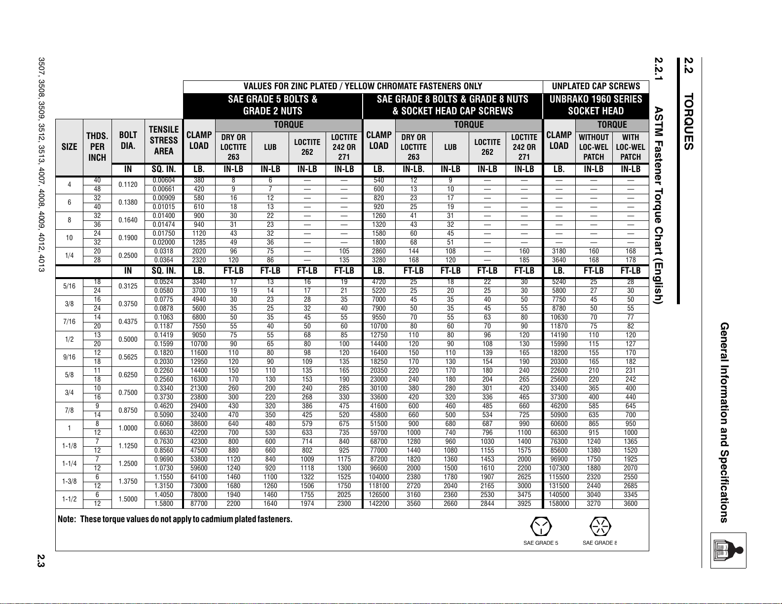
2.2.1 ASTM Fastener Torque Chart (English) . . . . . . . . . . . . . . . . . . . . . . . . . . 2.3
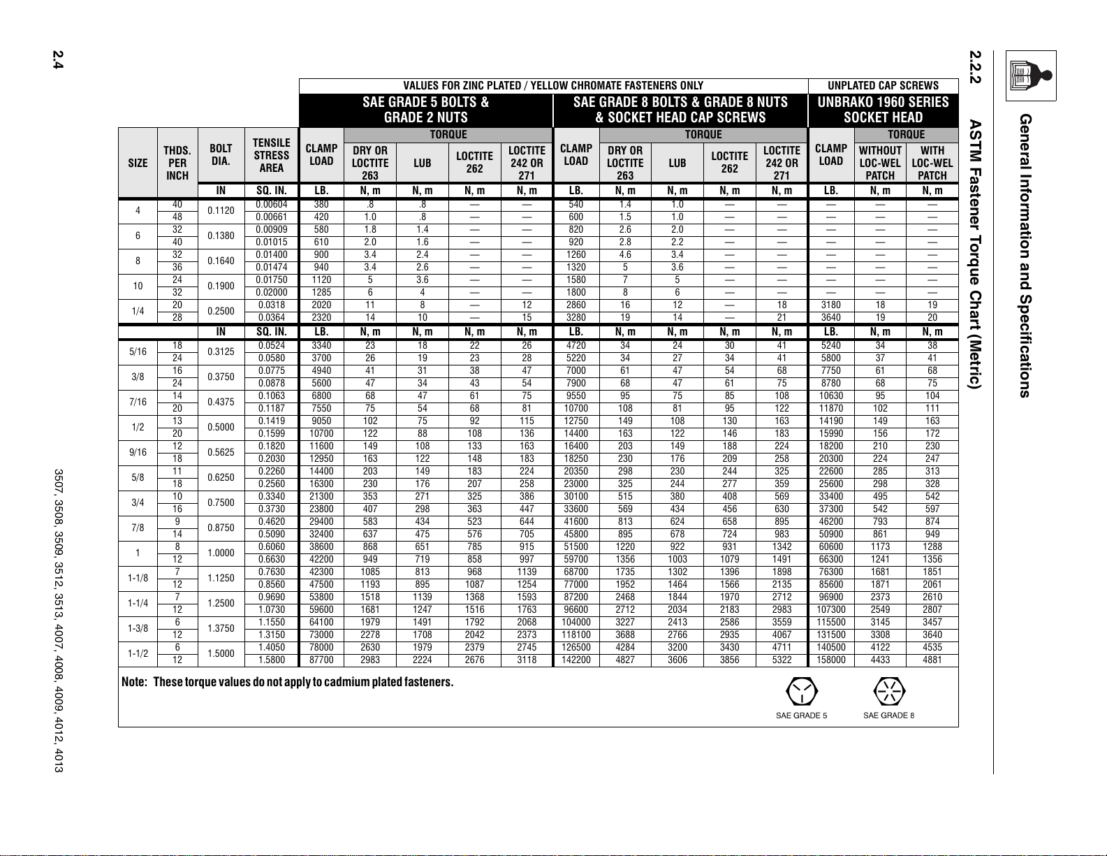
2.2.2 ASTM Fastener Torque Chart (Metric) . . . . . . . . . . . . . . . . . . . . . . . . . . . 2.4
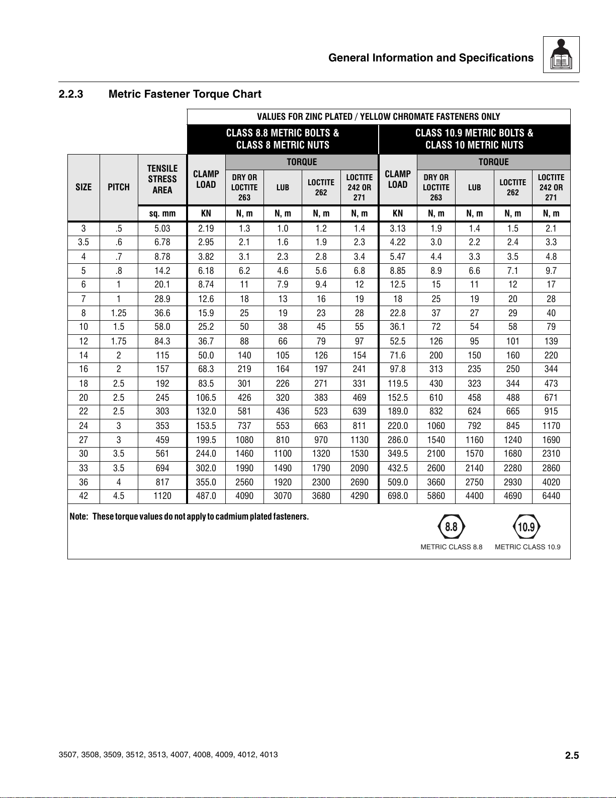
2.2.3 Metric Fastener Torque Chart . . . . . . . . . . . . . . . . . . . . . . . . . . . . . . . . . . 2.5
2.3 Specifications . . . . . . . . . . . . . . . . . . . . . . . . . . . . . . . . . . . . . . . . . . . . . . . . . . . . . 2.6
2.3.1 Travel Speeds . . . . . . . . . . . . . . . . . . . . . . . . . . . . . . . . . . . . . . . . . . . . . . 2.6
2.3.2 Hydraulic Cylinder Performance Specifications. . . . . . . . . . . . . . . . . . . . . 2.6
2.3.3 Electrical System . . . . . . . . . . . . . . . . . . . . . . . . . . . . . . . . . . . . . . . . . . . . 2.6
2.3.4 Engine Performance Specifications. . . . . . . . . . . . . . . . . . . . . . . . . . . . . . 2.7
2.3.5 Tires . . . . . . . . . . . . . . . . . . . . . . . . . . . . . . . . . . . . . . . . . . . . . . . . . . . . . 2.7
2.4 Fluids, Lubricants and Capacities . . . . . . . . . . . . . . . . . . . . . . . . . . . . . . . . . . . . . 2.8
2.5 Maintenance Schedules . . . . . . . . . . . . . . . . . . . . . . . . . . . . . . . . . . . . . . . . . . . . . 2.9
2.5.1 8 & 1st 50 Hour Maintenance Schedule . . . . . . . . . . . . . . . . . . . . . . . . . . 2.9
2.5.2 50, 250 & 500 Hour Maintenance Schedule . . . . . . . . . . . . . . . . . . . . . . . 2.9
2.5.3 1000 & 1500 Hour Maintenance Schedule . . . . . . . . . . . . . . . . . . . . . . . . 2.9
2.6 Lubrication Schedules . . . . . . . . . . . . . . . . . . . . . . . . . . . . . . . . . . . . . . . . . . . . . . 2.10
2.6.1 8 Hour Lubrication Schedule . . . . . . . . . . . . . . . . . . . . . . . . . . . . . . . . . . . 2.10
2.6.2 50 Hour Lubrication Schedule . . . . . . . . . . . . . . . . . . . . . . . . . . . . . . . . . . 2.11
3507, 3508, 3509, 3512, 3513, 4007, 4008, 4009, 4012, 4013
2.1
Courtesy of Crane.Market
General Information and Specifications
2.1 REPLACEMENT PARTS AND
WARRANTY INFORMATION
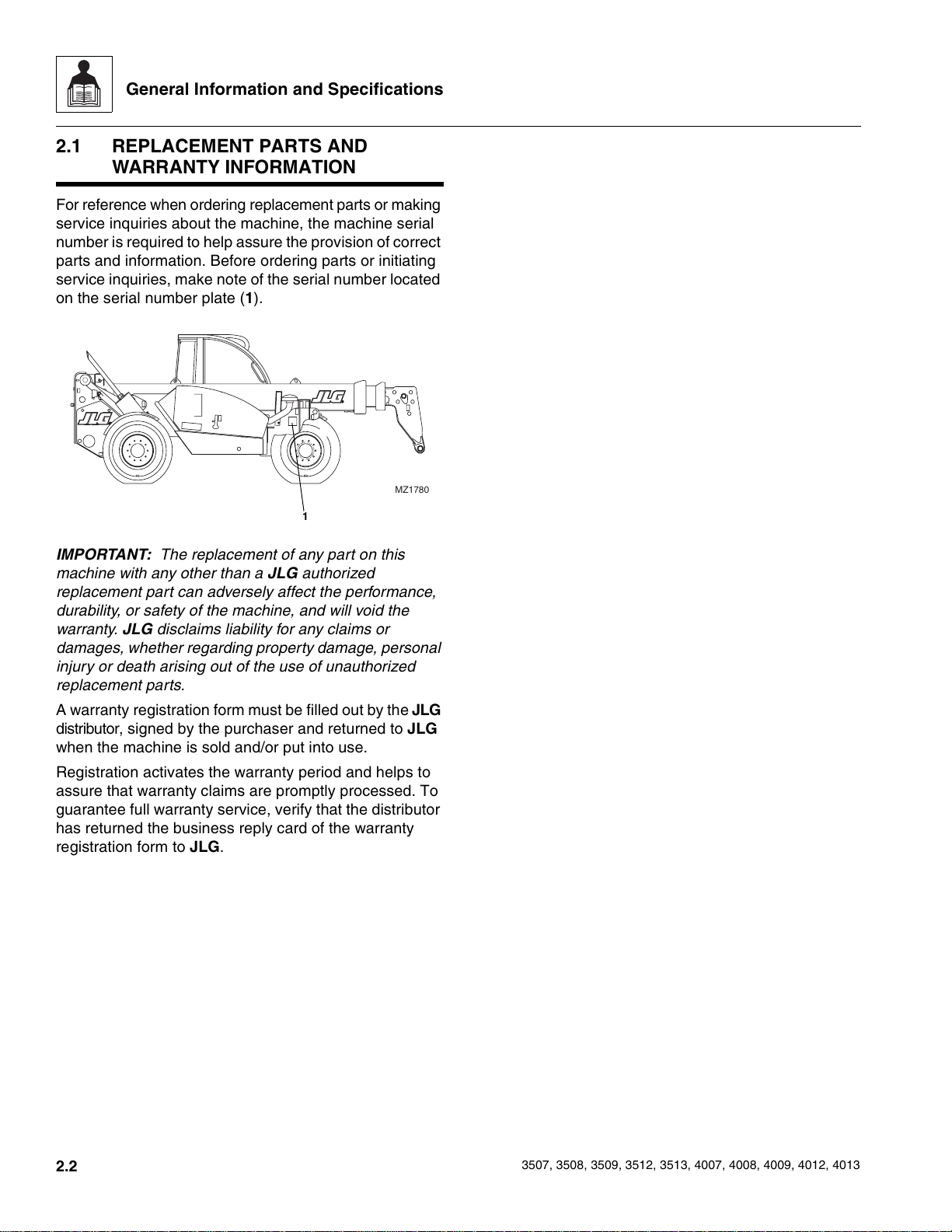
For reference when ordering replacement parts or making
service inquiries about the machine, the machine serial
number is required to help assure the provision of correct
parts and information. Before ordering parts or initiating
service inquiries, make note of the serial number located
on the serial number plate (1).
MZ1780
1
IMPORTANT: The replacement of any part on this
machine with any other than a JLG authorized
replacement part can adversely affect the performance,
durability, or safety of the machine, and will void the
warranty. JLG disclaims liability for any claims or
damages, whether regarding property damage, personal
injury or death arising out of the use of unauthorized
replacement parts.
A warranty registration form must be filled out by the JLG
distributor, signed by the purchaser and returned to JLG
when the machine is sold and/or put into use.
Registration activates the warranty period and helps to
assure that warranty claims are promptly processed. To
guarantee full warranty service, verify that the distributor
has returned the business reply card of the warranty
registration form to JLG.
2.2
3507, 3508, 3509, 3512, 3513, 4007, 4008, 4009, 4012, 4013
Courtesy of Crane.Market
3507, 3508, 3509, 3512, 3513, 4007, 4008, 4009, 4012, 4013
VALUES FOR ZINC PLATED / YELLOW CHROMATE FASTENERS ONLY UNPLATED CAP SCREWS
SAE GRADE 5 BOLTS &
GRADE 2 NUTS
TENSILE
PER
BOLT
DIA.
STRESS
AREA
THDS.
SIZE
INCH
IN SQ. IN. LB. IN-LB IN-LB IN-LB IN-LB LB. IN-LB. IN-LB IN-LB IN-LB LB. IN-LB IN-LB
40
4
6
8
10
1/4
0.1120
48 0.00661 420 9 7 — — 600 13 10 — — — — —
32
0.1380
40 0.01015 610 18 13 — — 920 25 19 — — — — —
32
0.1640
36 0.01474 940 31 23 — — 1320 43 32 — — — — —
24
0.1900
32 0.02000 1285 49 36 — — 1800 68 51 — — — — —
20
0.2500
28 0.0364 2320 120 86 — 135 3280 168 120 — 185 3640 168 178
0.00604 380 8 6 — — 540 12 9 — — — — —
0.00909 580 16 12 — — 820 23 17 — — — — —
0.01400 900 30 22 — — 1260 41 31 — — — — —
0.01750 1120 43 32 — — 1580 60 45 — — — — —
0.0318 2020 96 75 — 105 2860 144 108 — 160 3180 160 168
IN SQ. IN. LB. FT-LB FT-LB FT-LB FT-LB LB. FT-LB FT-LB FT-LB FT-LB LB. FT-LB FT-LB
5/16
3/8
7/16
1/2
9/16
5/8
3/4
7/8
1
1-1/8
1-1/4
1-3/8
1-1/2
18
0.3125
24 0.0580 3700 19 14 17 21 5220 25 20 25 30 5800 27 30
16
0.3750
24 0.0878 5600 35 25 32 40 7900 50 35 45 55 8780 50 55
14
0.4375
20 0.1187 7550 55 40 50 60 10700 80 60 70 90 11870 75 82
13
0.5000
20 0.1599 10700 90 65 80 100 14400 120 90 108 130 15990 115 127
12
0.5625
18 0.2030 12950 120 90 109 135 18250 170 130 154 190 20300 165 182
11
0.6250
18 0.2560 16300 170 130 153 190 23000 240 180 204 265 25600 220 242
10
0.7500
16 0.3730 23800 300 220 268 330 33600 420 320 336 465 37300 400 440
9
0.8750
14 0.5090 32400 470 350 425 520 45800 660 500 534 725 50900 635 700
8
1.0000
12 0.6630 42200 700 530 633 735 59700 1000 740 796 1100 66300 915 1000
7
1.1250
12 0.8560 47500 880 660 802 925 77000 1440 1080 1155 1575 85600 1380 1520
7
1.2500
12 1.0730 59600 1240 920 1118 1300 96600 2000 1500 1610 2200 107300 1880 2070
6
1.3750
12 1.3150 73000 1680 1260 1506 1750 118100 2720 2040 2165 3000 131500 2440 2685
6
1.5000
12 1.5800 87700 2200 1640 1974 2300 142200 3560 2660 2844 3925 158000 3270 3600
0.0524 3340 17 13 16 19 4720 25 18 22 30 5240 25 28
0.0775 4940 30 23 28 35 7000 45 35 40 50 7750 45 50
0.1063 6800 50 35 45 55 9550 70 55 63 80 10630 70 77
0.1419 9050 75 55 68 85 12750 110 80 96 120 14190 110 120
0.1820 11600 110 80 98 120 16400 150 110 139 165 18200 155 170
0.2260 14400 150 110 135 165 20350 220 170 180 240 22600 210 231
0.3340 21300 260 200 240 285 30100 380 280 301 420 33400 365 400
0.4620 29400 430 320 386 475 41600 600 460 485 660 46200 585 645
0.6060 38600 640 480 579 675 51500 900 680 687 990 60600 865 950
0.7630 42300 800 600 714 840 68700 1280 960 1030 1400 76300 1240 1365
0.9690 53800 1120 840 1009 1175 87200 1820 1360 1453 2000 96900 1750 1925
1.1550 64100 1460 1100 1322 1525 104000 2380 1780 1907 2625 115500 2320 2550
1.4050 78000 1940 1460 1755 2025 126500 3160 2360 2530 3475 140500 3040 3345
Note: These torque values do not apply to cadmium plated fasteners.
CLAMP
LOAD
DRY OR
LOCTITE
263
TORQUE
LUB
LOCTITE
262
LOCTITE
242 OR
271
SAE GRADE 8 BOLTS & GRADE 8 NUTS
& SOCKET HEAD CAP SCREWS
TORQUE
CLAMP
LOAD
DRY OR
LOCTITE
263
LUB
LOCTITE
262
LOCTITE
242 OR
271
UNBRAKO 1960 SERIES
SOCKET HEAD
TORQUE
CLAMP
LOAD
WITHOUT
LOC-WEL
PATCH
WITH
LOC-WEL
PATCH
2.2.1 ASTM Fastener Torque Chart (English)
2.2 TORQUES
General Information and Specifications
2.3
Courtesy of Crane.Market
2.4
2.2.2 ASTM Fastener Torque Chart (Metric)
3507, 3508, 3509, 3512, 3513, 4007, 4008, 4009, 4012, 4013
VALUES FOR ZINC PLATED / YELLOW CHROMATE FASTENERS ONLY UNPLATED CAP SCREWS
SAE GRADE 5 BOLTS &
GRADE 2 NUTS
TORQUE
LUB
SIZE
THDS.
PER
INCH
BOLT
DIA.
TENSILE
STRESS
AREA
CLAMP
LOAD
DRY OR
LOCTITE
263
IN SQ. IN. LB. N, m N, m N, m N, m LB. N, m N, m N, m N, m LB. N, m N, m
40
4
6
8
10
1/4
0.1120
48 0.00661 420 1.0 .8 — — 600 1.5 1.0 — — — — —
32
0.1380
40 0.01015 610 2.0 1.6 — — 920 2.8 2.2 — — — — —
32
0.1640
36 0.01474 940 3.4 2.6 — — 1320 5 3.6 — — — — —
24
0.1900
32 0.02000 1285 6 4 — — 1800 8 6 — — — — —
20
0.2500
28 0.0364 2320 14 10 — 15 3280 19 14 — 21 3640 19 20
0.00604 380 .8 .8 — — 540 1.4 1.0 — — — — —
0.00909 580 1.8 1.4 — — 820 2.6 2.0 — — — — —
0.01400 900 3.4 2.4 — — 1260 4.6 3.4 — — — — —
0.01750 1120 5 3.6 — — 1580 7 5 — — — — —
0.0318 2020 11 8 — 12 2860 16 12 — 18 3180 18 19
IN SQ. IN. LB. N, m N, m N, m N, m LB. N, m N, m N, m N, m LB. N, m N, m
5/16
3/8
7/16
1/2
9/16
5/8
3/4
7/8
1
1-1/8
1-1/4
1-3/8
1-1/2
18
0.3125
24 0.0580 3700 26 19 23 28 5220 34 27 34 41 5800 37 41
16
0.3750
24 0.0878 5600 47 34 43 54 7900 68 47 61 75 8780 68 75
14
0.4375
20 0.1187 7550 75 54 68 81 10700 108 81 95 122 11870 102 111
13
0.5000
20 0.1599 10700 122 88 108 136 14400 163 122 146 183 15990 156 172
12
0.5625
18 0.2030 12950 163 122 148 183 18250 230 176 209 258 20300 224 247
11
0.6250
18 0.2560 16300 230 176 207 258 23000 325 244 277 359 25600 298 328
10
0.7500
16 0.3730 23800 407 298 363 447 33600 569 434 456 630 37300 542 597
9
0.8750
14 0.5090 32400 637 475 576 705 45800 895 678 724 983 50900 861 949
8
1.0000
12 0.6630 42200 949 719 858 997 59700 1356 1003 1079 1491 66300 1241 1356
7
1.1250
12 0.8560 47500 1193 895 1087 1254 77000 1952 1464 1566 2135 85600 1871 2061
7
1.2500
12 1.0730 59600 1681 1247 1516 1763 96600 2712 2034 2183 2983 107300 2549 2807
6
1.3750
12 1.3150 73000 2278 1708 2042 2373 118100 3688 2766 2935 4067 131500 3308 3640
6
1.5000
12 1.5800 87700 2983 2224 2676 3118 142200 4827 3606 3856 5322 158000 4433 4881
0.0524 3340 23 18 22 26 4720 34 24 30 41 5240 34 38
0.0775 4940 41 31 38 47 7000 61 47 54 68 7750 61 68
0.1063 6800 68 47 61 75 9550 95 75 85 108 10630 95 104
0.1419 9050 102 75 92 115 12750 149 108 130 163 14190 149 163
0.1820 11600 149 108 133 163 16400 203 149 188 224 18200 210 230
0.2260 14400 203 149 183 224 20350 298 230 244 325 22600 285 313
0.3340 21300 353 271 325 386 30100 515 380 408 569 33400 495 542
0.4620 29400 583 434 523 644 41600 813 624 658 895 46200 793 874
0.6060 38600 868 651 785 915 51500 1220 922 931 1342 60600 1173 1288
0.7630 42300 1085 813 968 1139 68700 1735 1302 1396 1898 76300 1681 1851
0.9690 53800 1518 1139 1368 1593 87200 2468 1844 1970 2712 96900 2373 2610
1.1550 64100 1979 1491 1792 2068 104000 3227 2413 2586 3559 115500 3145 3457
1.4050 78000 2630 1979 2379 2745 126500 4284 3200 3430 4711 140500 4122 4535
Note: These torque values do not apply to cadmium plated fasteners.
LOCTITE
262
LOCTITE
242 OR
271
SAE GRADE 8 BOLTS & GRADE 8 NUTS
& SOCKET HEAD CAP SCREWS
LUB
TORQUE
LOCTITE
262
CLAMP
LOAD
DRY OR
LOCTITE
263
LOCTITE
242 OR
271
UNBRAKO 1960 SERIES
SOCKET HEAD
CLAMP
LOAD
TORQUE
WITHOUT
LOC-WEL
PATCH
WITH
LOC-WEL
PATCH
General Information and Specifications
Courtesy of Crane.Market
General Information and Specifications
9
2.2.3 Metric Fastener Torque Chart
VALUES FOR ZINC PLATED / YELLOW CHROMATE FASTENERS ONLY
CLASS 8.8 METRIC BOLTS &
CLASS 8 METRIC NUTS
TORQUE
LUB
LOCTITE
262
LOCTITE
242 OR
271
CLAMP
SIZE PITCH
TENSILE
STRESS
AREA
CLAMP
LOAD
DRY OR
LOCTITE
263
sq. mm KN N, m N, m N, m N, m KN N, m N, m N, m N, m
3 .5 5.03 2.19 1.3 1.0 1.2 1.4 3.13 1.9 1.4 1.5 2.1
3.5 .6 6.78 2.95 2.1 1.6 1.9 2.3 4.22 3.0 2.2 2.4 3.3
4 .7 8.78 3.82 3.1 2.3 2.8 3.4 5.47 4.4 3.3 3.5 4.8
5 .8 14.2 6.18 6.2 4.6 5.6 6.8 8.85 8.9 6.6 7.1 9.7
6 1 20.1 8.74 11 7.9 9.4 12 12.5 15 11 12 17
7 1 28.9 12.6 18 13 16 19 18 25 19 20 28
81.2536.615.92519232822.837272940
10 1.5 58.0 25.2 50 38 45 55 36.1 72 54 58 79
12 1.75 84.3 36.7 88 66 79 97 52.5 126 95 101 139
14 2 115 50.0 140 105 126 154 71.6 200 150 160 220
16 2 157 68.3 219 164 197 241 97.8 313 235 250 344
18 2.5 192 83.5 301 226 271 331 119.5 430 323 344 473
20 2.5 245 106.5 426 320 383 469 152.5 610 458 488 671
22 2.5 303 132.0 581 436 523 639 189.0 832 624 665 915
24 3 353 153.5 737 553 663 811 220.0 1060 792 845 1170
27 3 459 199.5 1080 810 970 1130 286.0 1540 1160 1240 1690
30 3.5 561 244.0 1460 1100 1320 1530 349.5 2100 1570 1680 2310
33 3.5 694 302.0 1990 1490 1790 2090 432.5 2600 2140 2280 2860
36 4 817 355.0 2560 1920 2300 2690 509.0 3660 2750 2930 4020
42 4.5 1120 487.0 4090 3070 3680 4290 698.0 5860 4400 4690 6440
CLASS 10.9 METRIC BOLTS &
CLASS 10 METRIC NUTS
LOAD
DRY OR
LOCTITE
263
LUB
TORQUE
LOCTITE
262
LOCTITE
242 OR
271
Note: These torque values do not apply to cadmium plated fasteners.
3507, 3508, 3509, 3512, 3513, 4007, 4008, 4009, 4012, 4013
METRIC CLASS 8.8METRIC CLASS 10.
2.5
Courtesy of Crane.Market
General Information and Specifications
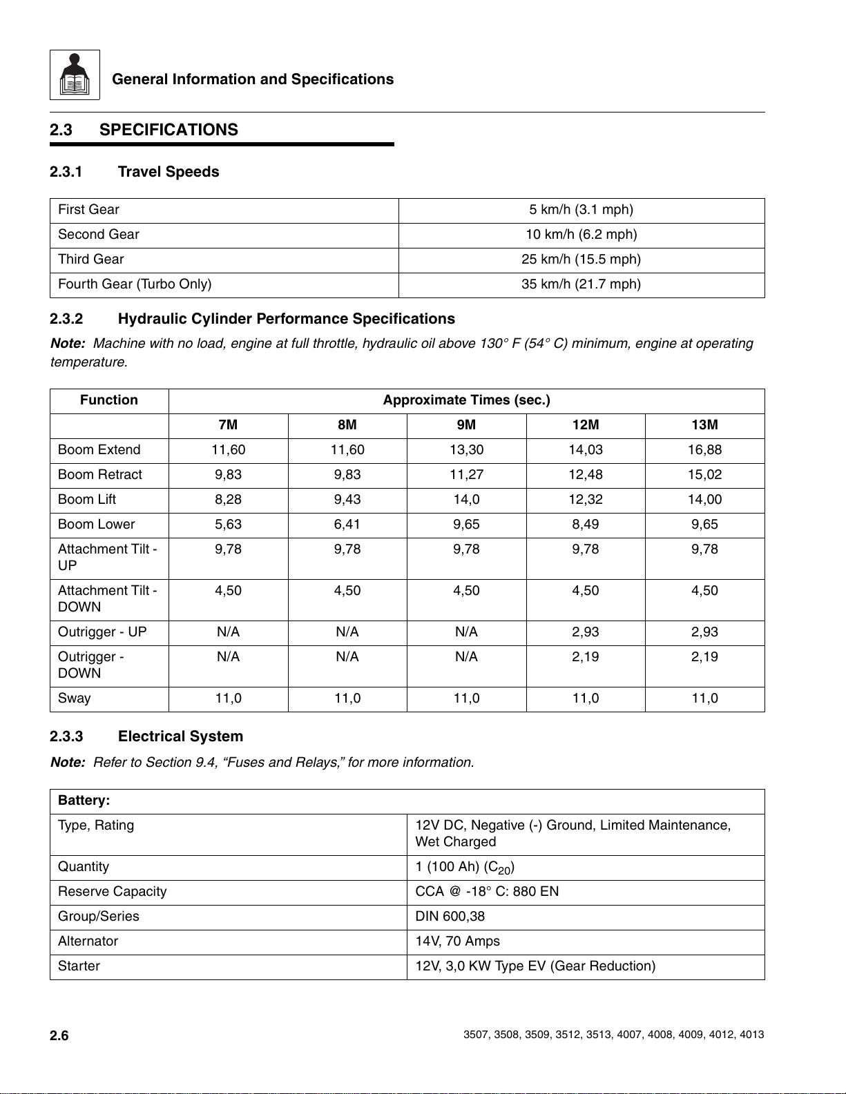
2.3 SPECIFICATIONS
2.3.1 Travel Speeds
First Gear 5 km/h (3.1 mph)
Second Gear 10 km/h (6.2 mph)
Third Gear 25 km/h (15.5 mph)
Fourth Gear (Turbo Only) 35 km/h (21.7 mph)
2.3.2 Hydraulic Cylinder Performance Specifications
Note: Machine with no load, engine at full throttle, hydraulic oil above 130° F (54° C) minimum, engine at operating
temperature.
Function Approximate Times (sec.)
7M 8M 9M 12M 13M
Boom Extend 11,60 11,60 13,30 14,03 16,88
Boom Retract 9,83 9,83 11,27 12,48 15,02
Boom Lift 8,28 9,43 14,0 12,32 14,00
Boom Lower 5,63 6,41 9,65 8,49 9,65
Attachment Tilt -
9,78 9,78 9,78 9,78 9,78
UP
Attachment Tilt -
4,50 4,50 4,50 4,50 4,50
DOWN
Outrigger - UP N/A N/A N/A 2,93 2,93
Outrigger -
N/A N/A N/A 2,19 2,19
DOWN
Sway 11,0 11,0 11,0 11,0 11,0
2.3.3 Electrical System
Note: Refer to Section 9.4, “Fuses and Relays,” for more information.
Battery:
Type, Rating 12V DC, Negative (-) Ground, Limited Maintenance,
Wet Charged
Quantity 1 (100 Ah) (C
Reserve Capacity CCA @ -18° C: 880 EN
20
)
Group/Series DIN 600,38
Alternator 14V, 70 Amps
Starter 12V, 3,0 KW Type EV (Gear Reduction)
2.6
3507, 3508, 3509, 3512, 3513, 4007, 4008, 4009, 4012, 4013
Courtesy of Crane.Market
General Information and Specifications
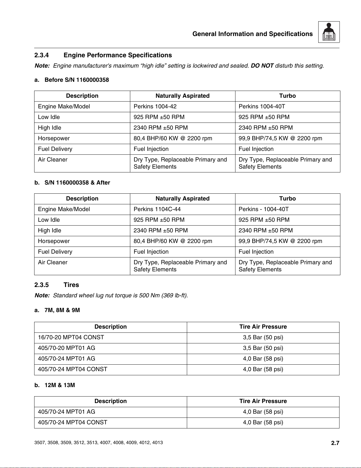
2.3.4 Engine Performance Specifications
Note: Engine manufacturer's maximum “high idle” setting is lockwired and sealed. DO NOT disturb this setting.
a. Before S/N 1160000358
Description Naturally Aspirated Turbo
Engine Make/Model Perkins 1004-42 Perkins 1004-40T
Low Idle 925 RPM ±50 RPM 925 RPM ±50 RPM
High Idle 2340 RPM ±50 RPM 2340 RPM ±50 RPM
Horsepower 80,4 BHP/60 KW @ 2200 rpm 99,9 BHP/74,5 KW @ 2200 rpm
Fuel Delivery Fuel Injection Fuel Injection
Air Cleaner Dry Type, Replaceable Primary and
Safety Elements
Dry Type, Replaceable Primary and
Safety Elements
b. S/N 1160000358 & After
Description Naturally Aspirated Turbo
Engine Make/Model Perkins 1104C-44 Perkins - 1004-40T
Low Idle 925 RPM ±50 RPM 925 RPM ±50 RPM
High Idle 2340 RPM ±50 RPM 2340 RPM ±50 RPM
Horsepower 80,4 BHP/60 KW @ 2200 rpm 99,9 BHP/74,5 KW @ 2200 rpm
Fuel Delivery Fuel Injection Fuel Injection
Air Cleaner Dry Type, Replaceable Primary and
Safety Elements
Dry Type, Replaceable Primary and
Safety Elements
2.3.5 Tires
Note: Standard wheel lug nut torque is 500 Nm (369 lb-ft).
a. 7M, 8M & 9M
Description Tire Air Pressure
16/70-20 MPT04 CONST 3,5 Bar (50 psi)
405/70-20 MPT01 AG 3,5 Bar (50 psi)
405/70-24 MPT01 AG 4,0 Bar (58 psi)
405/70-24 MPT04 CONST 4,0 Bar (58 psi)
b. 12M & 13M
Description Tire Air Pressure
405/70-24 MPT01 AG 4,0 Bar (58 psi)
405/70-24 MPT04 CONST 4,0 Bar (58 psi)
3507, 3508, 3509, 3512, 3513, 4007, 4008, 4009, 4012, 4013
2.7
Courtesy of Crane.Market
General Information and Specifications
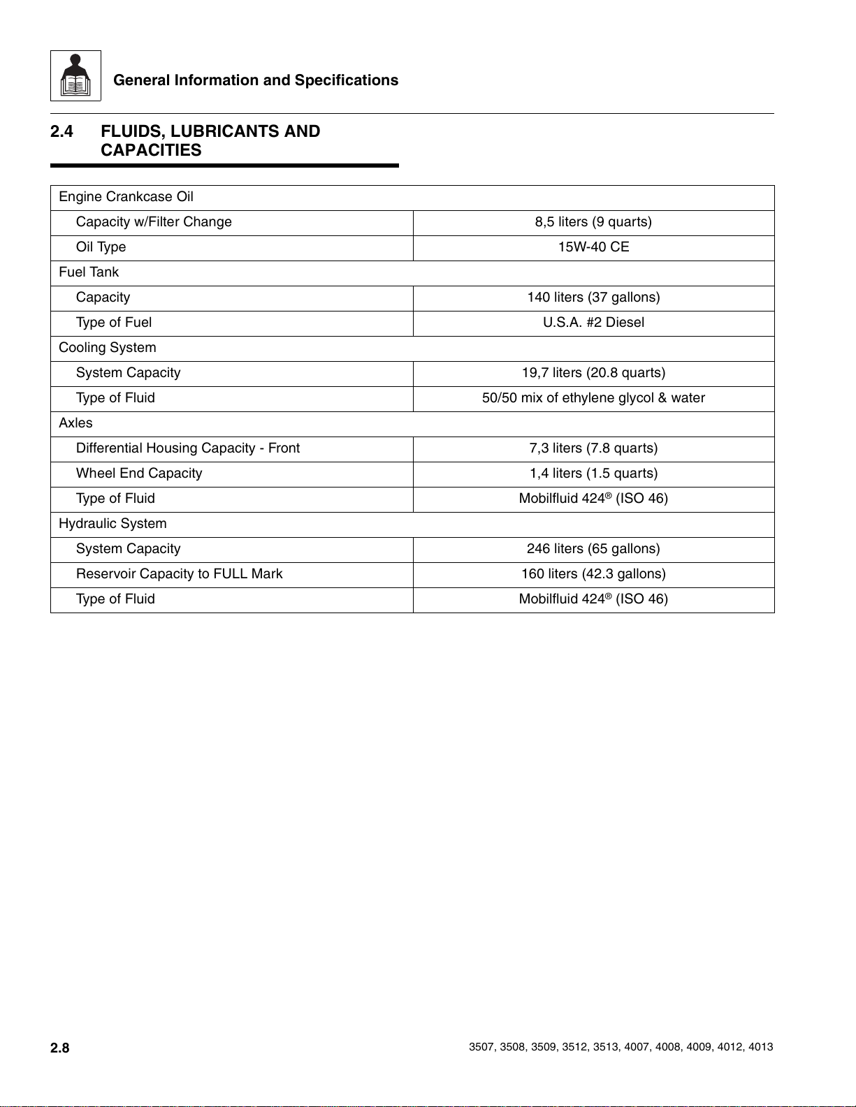
2.4 FLUIDS, LUBRICANTS AND
CAPACITIES
Engine Crankcase Oil
Capacity w/Filter Change 8,5 liters (9 quarts)
Oil Type 15W-40 CE
Fuel Tank
Capacity 140 liters (37 gallons)
Type of Fuel U.S.A. #2 Diesel
Cooling System
System Capacity 19,7 liters (20.8 quarts)
Type of Fluid 50/50 mix of ethylene glycol & water
Axles
Differential Housing Capacity - Front 7,3 liters (7.8 quarts)
Wheel End Capacity 1,4 liters (1.5 quarts)
Type of Fluid Mobilfluid 424
®
(ISO 46)
Hydraulic System
System Capacity 246 liters (65 gallons)
Reservoir Capacity to FULL Mark 160 liters (42.3 gallons)
Type of Fluid Mobilfluid 424
®
(ISO 46)
2.8
3507, 3508, 3509, 3512, 3513, 4007, 4008, 4009, 4012, 4013
Courtesy of Crane.Market
General Information and Specifications
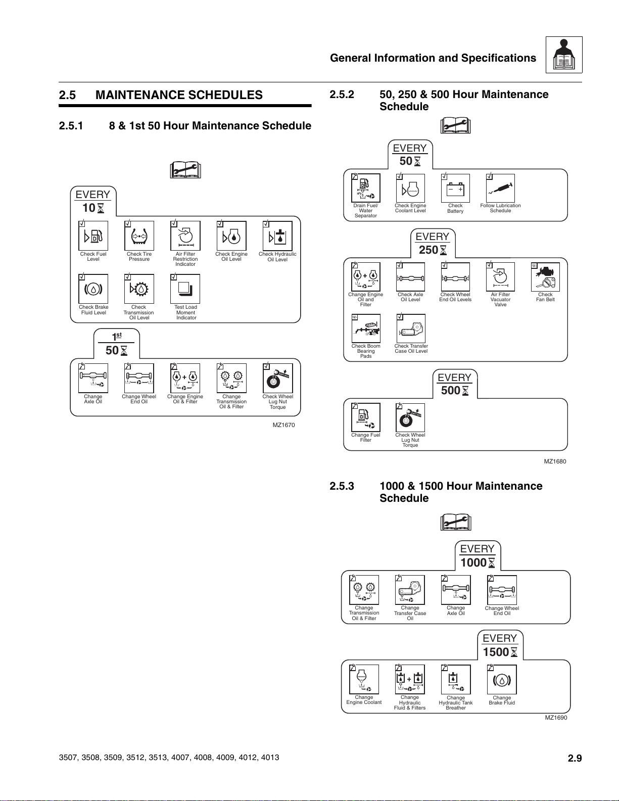
2.5 MAINTENANCE SCHEDULES
2.5.1 8 & 1st 50 Hour Maintenance Schedule
EVERY
10
Check Fuel
Level
Check Brake
Fluid Level
st
1
Check Tire
Pressure
Check
Transmission
Oil Level
Air Filter
Restriction
Indicator
Test Load
Moment
Indicator
Check Engine
Oil Level
Check Hydraulic
Oil Level
50
L
B/F
T (N
m)
Change
Axle Oil
Change Wheel
End Oil
Change Engine
Oil & Filter
Change
Transmission
Oil & Filter
Check Wheel
Lug Nut
Torque
MZ1670
2.5.2 50, 250 & 500 Hour Maintenance
Schedule
EVERY
50
Drain Fuel/
Water
Separator
Check Engine
Coolant Level
EVERY
Check
Battery
Follow Lubrication
Schedule
250
Change Engine
Oil and
Filter
Check Boom
Bearing
Pads
Check Axle
Oil Level
Check Transfer
Case Oil Level
Check Wheel
End Oil Levels
EVERY
Air Filter
Vacuator
Valve
Check
Fan Belt
500
LB/FT (Nm)
Change Fuel
Filter
Check Wheel
Lug Nut
Torque
MZ1680
3507, 3508, 3509, 3512, 3513, 4007, 4008, 4009, 4012, 4013
2.5.3 1000 & 1500 Hour Maintenance
Schedule
EVERY
1000
Change
Transmission
Oil & Filter
Change
Transfer Case
Oil
Change
Axle Oil
Change Wheel
End Oil
EVERY
1500
Change
Engine Coolant
Change
Hydraulic
Fluid & Filters
Change
Hydraulic Tank
Breather
Change
Brake Fluid
MZ1690
2.9
Courtesy of Crane.Market
General Information and Specifications
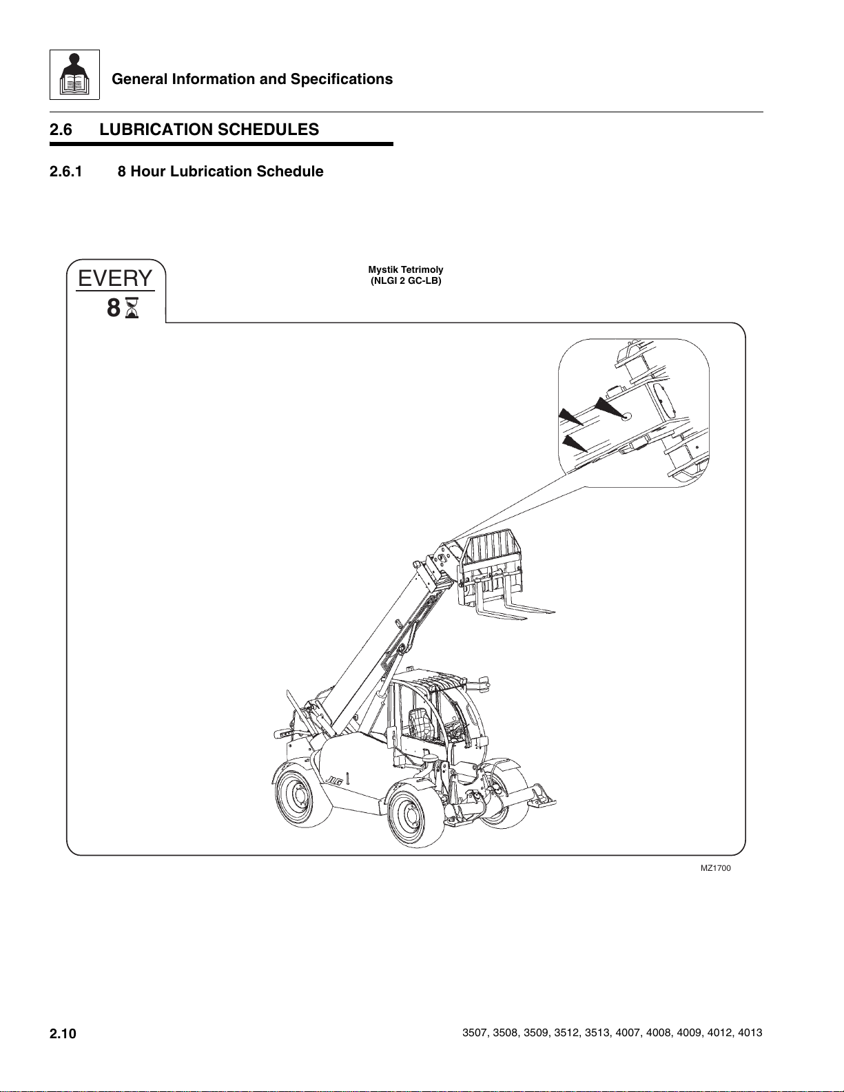
2.6 LUBRICATION SCHEDULES
2.6.1 8 Hour Lubrication Schedule
EVERY
8
Mystik Tetrimoly
(NLGI 2 GC-LB)
2.10
MZ1700
3507, 3508, 3509, 3512, 3513, 4007, 4008, 4009, 4012, 4013
Courtesy of Crane.Market
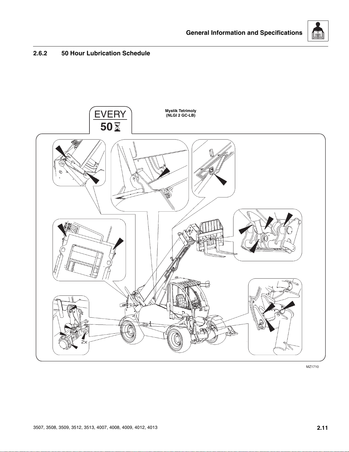
2.6.2 50 Hour Lubrication Schedule
EVERY
50
General Information and Specifications
Mystik Tetrimoly
(NLGI 2 GC-LB)
3507, 3508, 3509, 3512, 3513, 4007, 4008, 4009, 4012, 4013
MZ1710
2.11
Courtesy of Crane.Market

General Information and Specifications
This Page Intentionally Left Blank
2.12
3507, 3508, 3509, 3512, 3513, 4007, 4008, 4009, 4012, 4013
Courtesy of Crane.Market
Section 3
Boom
Contents
PARAGRAPH TITLE PAGE
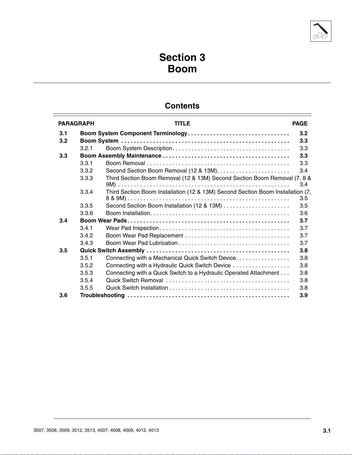
3.1 Boom System Component Terminology. . . . . . . . . . . . . . . . . . . . . . . . . . . . . . . . 3.2
3.2 Boom System . . . . . . . . . . . . . . . . . . . . . . . . . . . . . . . . . . . . . . . . . . . . . . . . . . . . . 3.3
3.2.1 Boom System Description. . . . . . . . . . . . . . . . . . . . . . . . . . . . . . . . . . . . . 3.3
3.3 Boom Assembly Maintenance . . . . . . . . . . . . . . . . . . . . . . . . . . . . . . . . . . . . . . . . 3.3
3.3.1 Boom Removal . . . . . . . . . . . . . . . . . . . . . . . . . . . . . . . . . . . . . . . . . . . . . 3.3
3.3.2 Second Section Boom Removal (12 & 13M). . . . . . . . . . . . . . . . . . . . . . . 3.4
3.3.3 Third Section Boom Removal (12 & 13M) Second Section Boom Removal (7, 8 &
9M) . . . . . . . . . . . . . . . . . . . . . . . . . . . . . . . . . . . . . . . . . . . . . . . . . . . . . . 3.4
3.3.4 Third Section Boom Installation (12 & 13M) Second Section Boom Installation (7,
8 & 9M) . . . . . . . . . . . . . . . . . . . . . . . . . . . . . . . . . . . . . . . . . . . . . . . . . . . 3.5
3.3.5 Second Section Boom Installation (12 & 13M) . . . . . . . . . . . . . . . . . . . . . 3.5
3.3.6 Boom Installation. . . . . . . . . . . . . . . . . . . . . . . . . . . . . . . . . . . . . . . . . . . . 3.6
3.4 Boom Wear Pads. . . . . . . . . . . . . . . . . . . . . . . . . . . . . . . . . . . . . . . . . . . . . . . . . . . 3.7
3.4.1 Wear Pad Inspection. . . . . . . . . . . . . . . . . . . . . . . . . . . . . . . . . . . . . . . . . 3.7
3.4.2 Boom Wear Pad Replacement . . . . . . . . . . . . . . . . . . . . . . . . . . . . . . . . . 3.7
3.4.3 Boom Wear Pad Lubrication . . . . . . . . . . . . . . . . . . . . . . . . . . . . . . . . . . . 3.7
3.5 Quick Switch Assembly . . . . . . . . . . . . . . . . . . . . . . . . . . . . . . . . . . . . . . . . . . . . . 3.8
3.5.1 Connecting with a Mechanical Quick Switch Device. . . . . . . . . . . . . . . . . 3.8
3.5.2 Connecting with a Hydraulic Quick Switch Device . . . . . . . . . . . . . . . . . . 3.8
3.5.3 Connecting with a Quick Switch to a Hydraulic Operated Attachment . . . 3.8
3.5.4 Quick Switch Removal . . . . . . . . . . . . . . . . . . . . . . . . . . . . . . . . . . . . . . . 3.8
3.5.5 Quick Switch Installation . . . . . . . . . . . . . . . . . . . . . . . . . . . . . . . . . . . . . . 3.8
3.6 Troubleshooting . . . . . . . . . . . . . . . . . . . . . . . . . . . . . . . . . . . . . . . . . . . . . . . . . . . 3.9
3507, 3508, 3509, 3512, 3513, 4007, 4008, 4009, 4012, 4013
3.1
Courtesy of Crane.Market
Boom
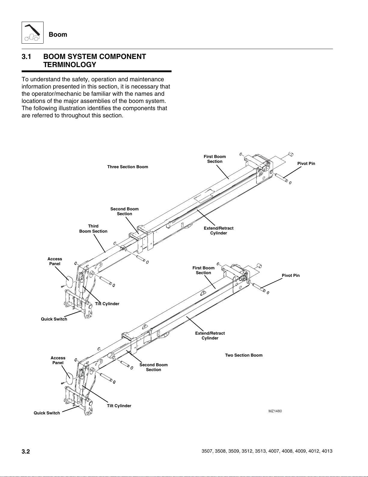
3.1 BOOM SYSTEM COMPONENT
TERMINOLOGY
To understand the safety, operation and maintenance
information presented in this section, it is necessary that
the operator/mechanic be familiar with the names and
locations of the major assemblies of the boom system.
The following illustration identifies the components that
are referred to throughout this section.
Three Section Boom
Second Boom
Section
First Boom
Section
Pivot Pin
Access
Panel
Quick Switch
Access
Panel
Third
Boom Section
Tilt Cylinder
Second Boom
Section
Extend/Retract
Cylinder
First Boom
Section
Extend/Retract
Cylinder
Pivot Pin
Two Section Boom
3.2
Quick Switch
Tilt Cylinder
MZ1480
3507, 3508, 3509, 3512, 3513, 4007, 4008, 4009, 4012, 4013
Courtesy of Crane.Market
Boom
3.2 BOOM SYSTEM
3.2.1 Boom System Description
The boom operates via an interchange among the
electrical, hydraulic and mechanical systems. Components
involved include the joystick, tilt cylinder, extend/retract
cylinder, lift/lower cylinder, compensation cylinder,
electronic sensors, various pivots, supporting hardware
and other components.
3.3 BOOM ASSEMBLY MAINTENANCE
IMPORTANT: Boom replacement must be completed in
sequence, one boom section at a time, as described in
these instructions.
Before beginning, conduct a visual inspection of the
machine and work area, and review the task about to be
undertaken. Read, understand and follow these
instructions.
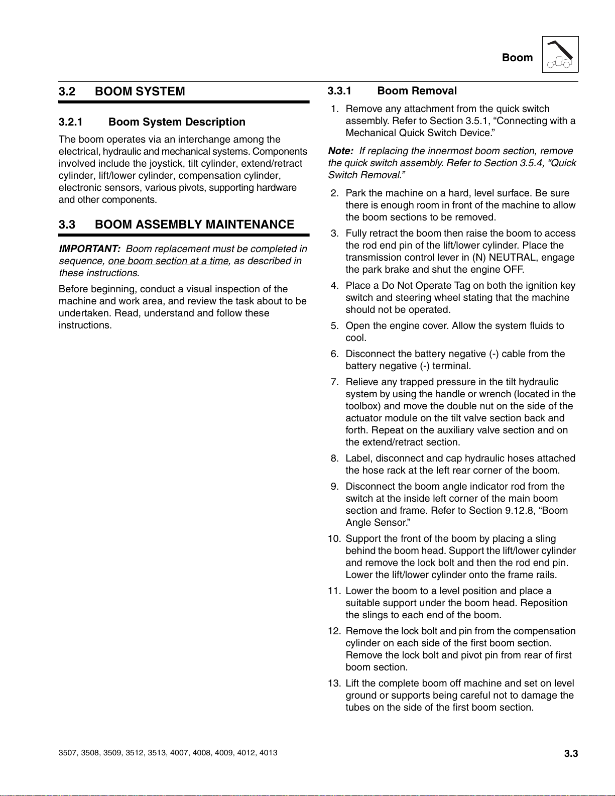
3.3.1 Boom Removal
1. Remove any attachment from the quick switch
assembly. Refer to Section 3.5.1, “Connecting with a
Mechanical Quick Switch Device.”
Note: If replacing the innermost boom section, remove
the quick switch assembly. Refer to Section 3.5.4, “Quick
Switch Removal.”
2. Park the machine on a hard, level surface. Be sure
there is enough room in front of the machine to allow
the boom sections to be removed.
3. Fully retract the boom then raise the boom to access
the rod end pin of the lift/lower cylinder. Place the
transmission control lever in (N) NEUTRAL, engage
the park brake and shut the engine OFF.
4. Place a Do Not Operate Tag on both the ignition key
switch and steering wheel stating that the machine
should not be operated.
5. Open the engine cover. Allow the system fluids to
cool.
6. Disconnect the battery negative (-) cable from the
battery negative (-) terminal.
7. Relieve any trapped pressure in the tilt hydraulic
system by using the handle or wrench (located in the
toolbox) and move the double nut on the side of the
actuator module on the tilt valve section back and
forth. Repeat on the auxiliary valve section and on
the extend/retract section.
8. Label, disconnect and cap hydraulic hoses attached
the hose rack at the left rear corner of the boom.
9. Disconnect the boom angle indicator rod from the
switch at the inside left corner of the main boom
section and frame. Refer to Section 9.12.8, “Boom
Angle Sensor.”
10. Support the front of the boom by placing a sling
behind the boom head. Support the lift/lower cylinder
and remove the lock bolt and then the rod end pin.
Lower the lift/lower cylinder onto the frame rails.
11. Lower the boom to a level position and place a
suitable support under the boom head. Reposition
the slings to each end of the boom.
12. Remove the lock bolt and pin from the compensation
cylinder on each side of the first boom section.
Remove the lock bolt and pivot pin from rear of first
boom section.
13. Lift the complete boom off machine and set on level
ground or supports being careful not to damage the
tubes on the side of the first boom section.
3507, 3508, 3509, 3512, 3513, 4007, 4008, 4009, 4012, 4013
3.3
Courtesy of Crane.Market
Boom
a. If the boom is going to be disassembled after
removal:
1. Set the complete boom on level ground and by
repositioning the slings, turn boom over on to the top
side. Set the complete boom on suitable stands to
begin teardown.
Note: With the complete boom setting upside down, the
other boom section(s), tilt cylinder and hoses are made
more accessible.
2. Remove the access panel from the boom head.
3. Label, disconnect and cap the hoses attached to the
tilt cylinder and the hose rack on the side of the first
boom section.
4. Attach a sling through the rod end of the tilt cylinder.
Remove the clip from the barrel end of the tilt
cylinder pin. Remove the tilt cylinder pin and lift the
tilt cylinder out of the boom head.
5. Remove the hose clamp inside the innermost boom
section.
6. Label, disconnect and cap the hoses attached to the
extend/retract cylinder at the rear of the boom.
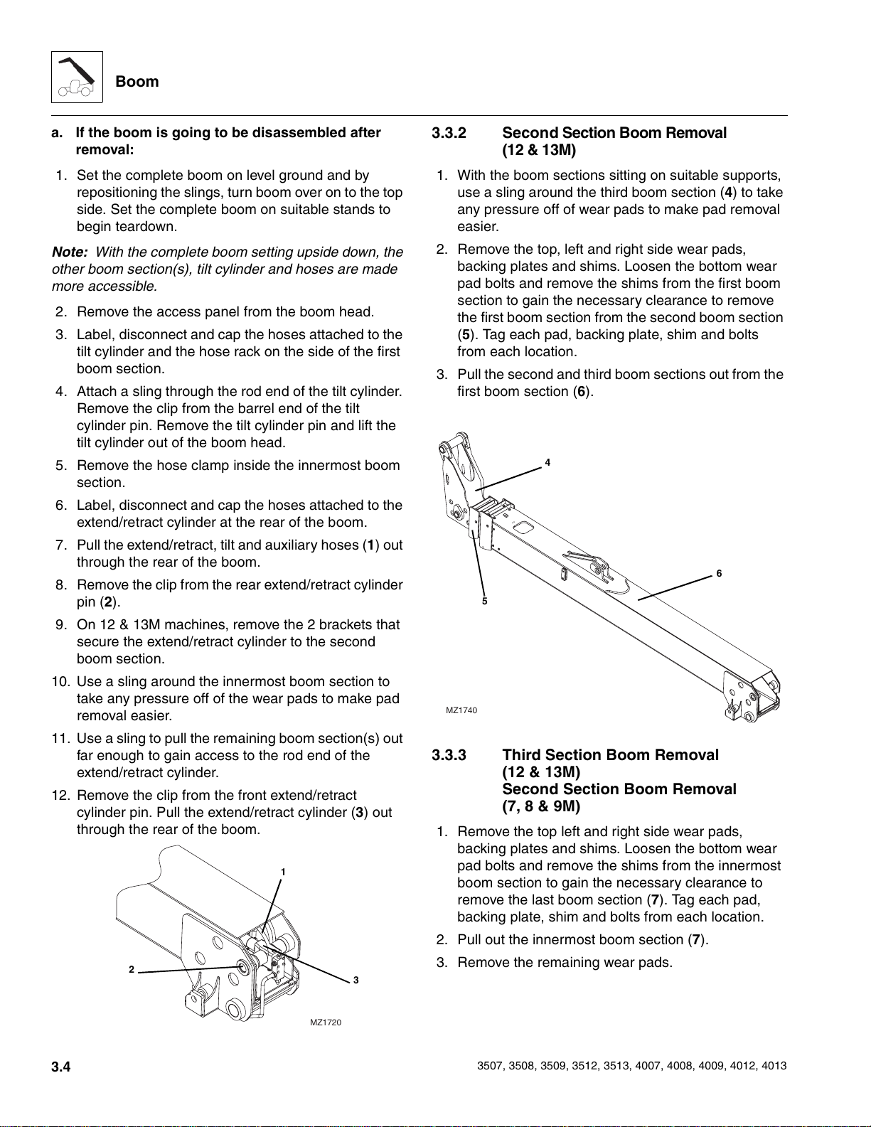
7. Pull the extend/retract, tilt and auxiliary hoses (1) out
through the rear of the boom.
8. Remove the clip from the rear extend/retract cylinder
pin (2).
9. On 12 & 13M machines, remove the 2 brackets that
secure the extend/retract cylinder to the second
boom section.
10. Use a sling around the innermost boom section to
take any pressure off of the wear pads to make pad
removal easier.
11. Use a sling to pull the remaining boom section(s) out
far enough to gain access to the rod end of the
extend/retract cylinder.
12. Remove the clip from the front extend/retract
cylinder pin. Pull the extend/retract cylinder (3) out
through the rear of the boom.
1
2
3
3.3.2 Second Section Boom Removal
(12 & 13M)
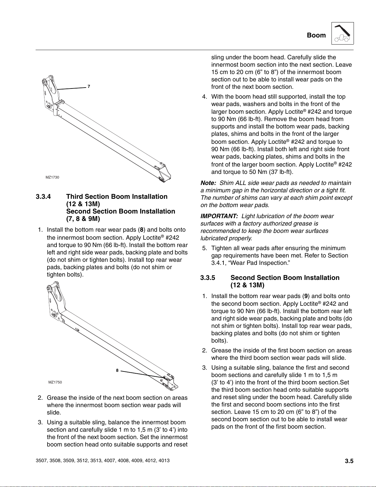
1. With the boom sections sitting on suitable supports,
use a sling around the third boom section (4) to take
any pressure off of wear pads to make pad removal
easier.
2. Remove the top, left and right side wear pads,
backing plates and shims. Loosen the bottom wear
pad bolts and remove the shims from the first boom
section to gain the necessary clearance to remove
the first boom section from the second boom section
(5). Tag each pad, backing plate, shim and bolts
from each location.
3. Pull the second and third boom sections out from the
first boom section (6).
4
6
5
MZ1740
3.3.3 Third Section Boom Removal
(12 & 13M)
Second Section Boom Removal
(7, 8 & 9M)
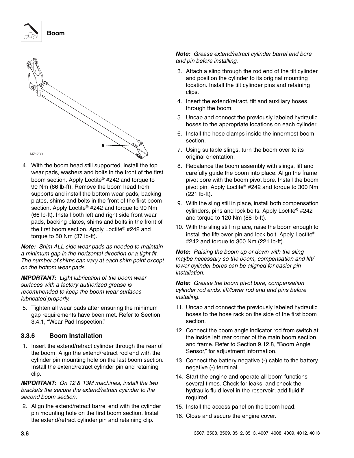
1. Remove the top left and right side wear pads,
backing plates and shims. Loosen the bottom wear
pad bolts and remove the shims from the innermost
boom section to gain the necessary clearance to
remove the last boom section (7). Tag each pad,
backing plate, shim and bolts from each location.
2. Pull out the innermost boom section (7).
3. Remove the remaining wear pads.
3.4
MZ1720
3507, 3508, 3509, 3512, 3513, 4007, 4008, 4009, 4012, 4013
Courtesy of Crane.Market
7
MZ1730
3.3.4 Third Section Boom Installation
(12 & 13M)
Second Section Boom Installation
(7, 8 & 9M)
1. Install the bottom rear wear pads (8) and bolts onto
the innermost boom section. Apply Loctite
and torque to 90 Nm (66 lb-ft). Install the bottom rear
left and right side wear pads, backing plate and bolts
(do not shim or tighten bolts). Install top rear wear
pads, backing plates and bolts (do not shim or
tighten bolts).
®
#242
Boom
sling under the boom head. Carefully slide the
innermost boom section into the next section. Leave
15 cm to 20 cm (6” to 8”) of the innermost boom
section out to be able to install wear pads on the
front of the next boom section.
4. With the boom head still supported, install the top
wear pads, washers and bolts in the front of the
larger boom section. Apply Loctite
®
#242 and torque
to 90 Nm (66 lb-ft). Remove the boom head from
supports and install the bottom wear pads, backing
plates, shims and bolts in the front of the larger
boom section. Apply Loctite
®
#242 and torque to
90 Nm (66 lb-ft). Install both left and right side front
wear pads, backing plates, shims and bolts in the
front of the larger boom section. Apply Loctite® #242
and torque to 50 Nm (37 lb-ft).
Note: Shim ALL side wear pads as needed to maintain
a minimum gap in the horizontal direction or a tight fit.
The number of shims can vary at each shim point except
on the bottom wear pads.
IMPORTANT: Light lubrication of the boom wear
surfaces with a factory authorized grease is
recommended to keep the boom wear surfaces
lubricated properly.
5. Tighten all wear pads after ensuring the minimum
gap requirements have been met. Refer to Section
3.4.1, “Wear Pad Inspection.”
3.3.5 Second Section Boom Installation
(12 & 13M)
8
MZ1750
2. Grease the inside of the next boom section on areas
where the innermost boom section wear pads will
slide.
3. Using a suitable sling, balance the innermost boom
section and carefully slide 1 m to 1,5 m (3’ to 4’) into
the front of the next boom section. Set the innermost
boom section head onto suitable supports and reset
3507, 3508, 3509, 3512, 3513, 4007, 4008, 4009, 4012, 4013
1. Install the bottom rear wear pads (9) and bolts onto
®
the second boom section. Apply Loctite
#242 and
torque to 90 Nm (66 lb-ft). Install the bottom rear left
and right side wear pads, backing plate and bolts (do
not shim or tighten bolts). Install top rear wear pads,
backing plates and bolts (do not shim or tighten
bolts).
2. Grease the inside of the first boom section on areas
where the third boom section wear pads will slide.
3. Using a suitable sling, balance the first and second
boom sections and carefully slide 1 m to 1,5 m
(3’ to 4’) into the front of the third boom section.Set
the third boom section head onto suitable supports
and reset sling under the boom head. Carefully slide
the first and second boom sections into the first
section. Leave 15 cm to 20 cm (6” to 8”) of the
second boom section out to be able to install wear
pads on the front of the first boom section.
3.5
Courtesy of Crane.Market
Boom
9
MZ1730
4. With the boom head still supported, install the top
wear pads, washers and bolts in the front of the first
boom section. Apply Loctite® #242 and torque to
90 Nm (66 lb-ft). Remove the boom head from
supports and install the bottom wear pads, backing
plates, shims and bolts in the front of the first boom
section. Apply Loctite® #242 and torque to 90 Nm
(66 lb-ft). Install both left and right side front wear
pads, backing plates, shims and bolts in the front of
the first boom section. Apply Loctite
®
#242 and
torque to 50 Nm (37 lb-ft).
Note: Shim ALL side wear pads as needed to maintain
a minimum gap in the horizontal direction or a tight fit.
The number of shims can vary at each shim point except
on the bottom wear pads.
IMPORTANT: Light lubrication of the boom wear
surfaces with a factory authorized grease is
recommended to keep the boom wear surfaces
lubricated properly.
5. Tighten all wear pads after ensuring the minimum
gap requirements have been met. Refer to Section
3.4.1, “Wear Pad Inspection.”
3.3.6 Boom Installation
1. Insert the extend/retract cylinder through the rear of
the boom. Align the extend/retract rod end with the
cylinder pin mounting hole on the last boom section.
Install the extend/retract cylinder pin and retaining
clip.
IMPORTANT: On 12 & 13M machines, install the two
brackets the secure the extend/retract cylinder to the
second boom section.
2. Align the extend/retract barrel end with the cylinder
pin mounting hole on the first boom section. Install
the extend/retract cylinder pin and retaining clip.
Note: Grease extend/retract cylinder barrel end bore
and pin before installing.
3. Attach a sling through the rod end of the tilt cylinder
and position the cylinder to its original mounting
location. Install the tilt cylinder pins and retaining
clips.
4. Insert the extend/retract, tilt and auxiliary hoses
through the boom.
5. Uncap and connect the previously labeled hydraulic
hoses to the appropriate locations on each cylinder.
6. Install the hose clamps inside the innermost boom
section.
7. Using suitable slings, turn the boom over to its
original orientation.
8. Rebalance the boom assembly with slings, lift and
carefully guide the boom into place. Align the frame
pivot bore with the boom pivot bore. Install the boom
pivot pin. Apply Loctite
®
#242 and torque to 300 Nm
(221 lb-ft).
9. With the sling still in place, install both compensation
cylinders, pins and lock bolts. Apply Loctite® #242
and torque to 120 Nm (88 lb-ft).
10. With the sling still in place, raise the boom enough to
install the lift/lower pin and lock bolt. Apply Loctite®
#242 and torque to 300 Nm (221 lb-ft).
Note: Raising the boom up or down with the sling
maybe necessary so the boom, compensation and lift/
lower cylinder bores can be aligned for easier pin
installation.
Note: Grease the boom pivot bore, compensation
cylinder rod ends, lift/lower rod end and pins before
installing.
11. Uncap and connect the previously labeled hydraulic
hoses to the hose rack on the side of the first boom
section.
12. Connect the boom angle indicator rod from switch at
the inside left rear corner of the main boom section
and frame. Refer to Section 9.12.8, “Boom Angle
Sensor,” for adjustment information.
13. Connect the battery negative (-) cable to the battery
negative (-) terminal.
14. Start the engine and operate all boom functions
several times. Check for leaks, and check the
hydraulic fluid level in the reservoir; add fluid if
required.
15. Install the access panel on the boom head.
16. Close and secure the engine cover.
3.6
3507, 3508, 3509, 3512, 3513, 4007, 4008, 4009, 4012, 4013
Courtesy of Crane.Market
3.4 BOOM WEAR PADS
The wear pads on this machine are flat rectangular wear
pads with metal inserts.
A total of 13 wear pads are installed on the boom sections
of the 7, 8 & 9M machines.
A total of 26 wear pads are installed on the boom sections
of the 12 & 13M machines.
3.4.1 Wear Pad Inspection
Inspect all wear pads for wear. If the angle indicators (10)
on the ends of the wear pads are visible, the wear pads
can be reused. If the pads show uneven wear (front to
back), they should be replaced. Replace pads as a set if
worn or damaged.
10
3.4.2 Boom Wear Pad Replacement
When replacing a wear pad on the boom, replace both
wear pads on that side of the boom; e.g.: replace top front
left and top front right wear pads at the same time.
Usually, shimming will remain the same when installing
new wear pads. All wear pads are secured to the boom
using different capscrews and washers. When installing
new wear pads, apply Loctite
mounting capscrews. Torque right and left side wear
pads to 50 Nm (36 lb-ft) and torque top and bottom side
wear pads to 90 Nm (66 lb-ft). Grease the new pads and
surrounding area.
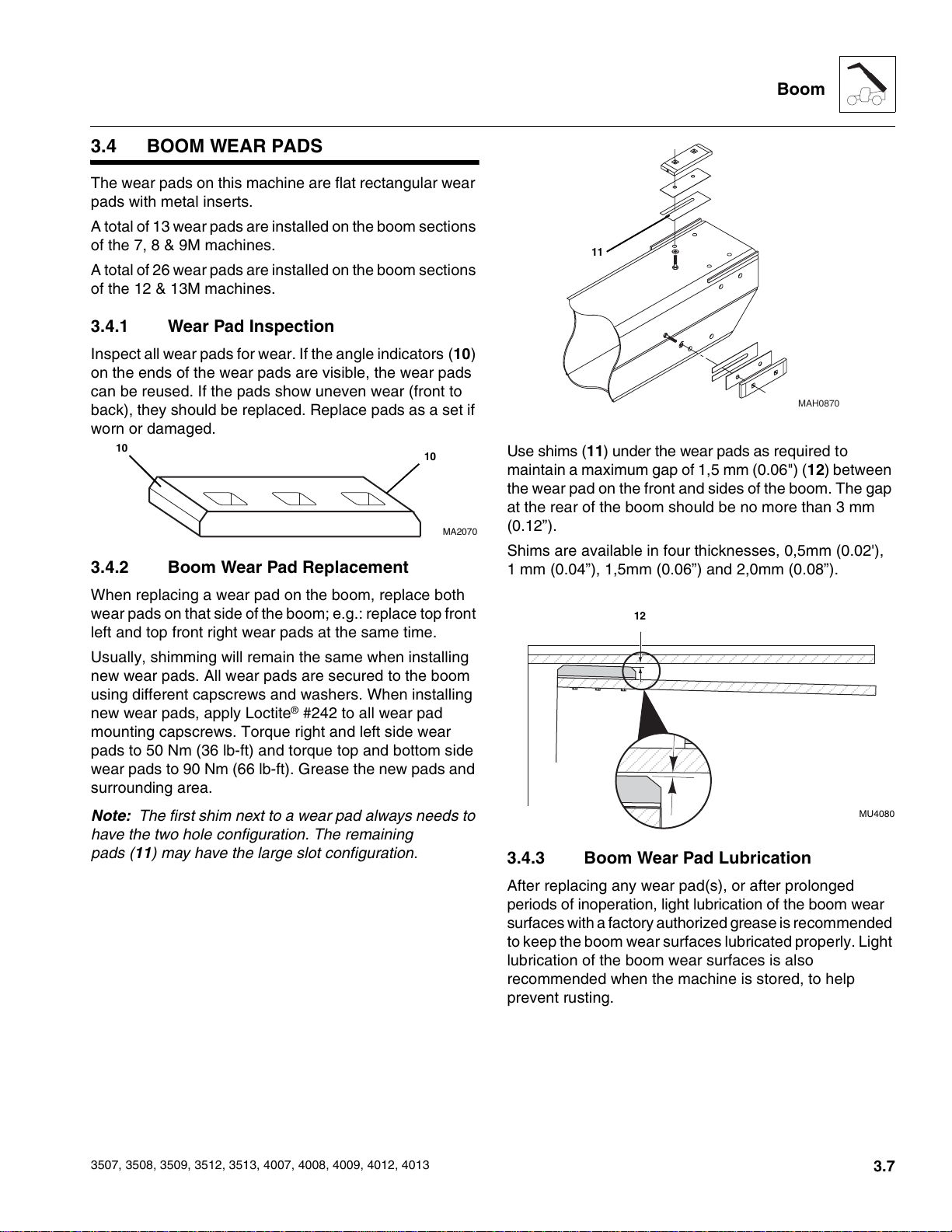
Note: The first shim next to a wear pad always needs to
have the two hole configuration. The remaining
pads (11) may have the large slot configuration.
®
#242 to all wear pad
10
MA2070
Boom
11
MAH0870
Use shims (11) under the wear pads as required to
maintain a maximum gap of 1,5 mm (0.06") (12) between
the wear pad on the front and sides of the boom. The gap
at the rear of the boom should be no more than 3 mm
(0.12”).
Shims are available in four thicknesses, 0,5mm (0.02'),
1 mm (0.04”), 1,5mm (0.06”) and 2,0mm (0.08”).
12
MU4080
3.4.3 Boom Wear Pad Lubrication
3507, 3508, 3509, 3512, 3513, 4007, 4008, 4009, 4012, 4013
After replacing any wear pad(s), or after prolonged
periods of inoperation, light lubrication of the boom wear
surfaces with a factory authorized grease is recommended
to keep the boom wear surfaces lubricated properly. Light
lubrication of the boom wear surfaces is also
recommended when the machine is stored, to help
prevent rusting.
3.7
Courtesy of Crane.Market
Boom
3.5 QUICK SWITCH ASSEMBLY
This machine is equipped with a quick switch system for
easy attachment changes.
3.5.1 Connecting with a Mechanical Quick
Switch Device
1. Retract quick switch device to provide clearance.
Check to be sure lock pin (13) and retainer pin (14)
is out.
2. Align attachment pin (15) with recess in
attachment (16). Raise boom slightly to engage
attachment pin in recess.
3. Engage quick switch device.
4. Shut off engine. Exit cab and insert lick pin and
secure with retainer pin.
5. If attachment is equipped, connect auxiliary
hydraulic hoses. See Section 3.5.3, “Connecting with
a Quick Switch to a Hydraulic Operated Attachment.”
3.5.2 Connecting with a Hydraulic Quick
Switch Device
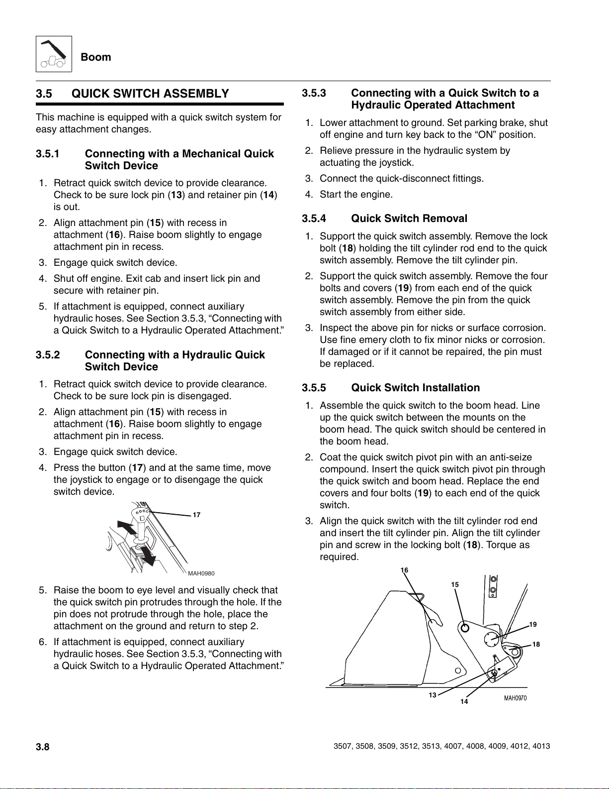
3.5.3 Connecting with a Quick Switch to a
Hydraulic Operated Attachment
1. Lower attachment to ground. Set parking brake, shut
off engine and turn key back to the “ON” position.
2. Relieve pressure in the hydraulic system by
actuating the joystick.
3. Connect the quick-disconnect fittings.
4. Start the engine.
3.5.4 Quick Switch Removal
1. Support the quick switch assembly. Remove the lock
bolt (18) holding the tilt cylinder rod end to the quick
switch assembly. Remove the tilt cylinder pin.
2. Support the quick switch assembly. Remove the four
bolts and covers (19) from each end of the quick
switch assembly. Remove the pin from the quick
switch assembly from either side.
3. Inspect the above pin for nicks or surface corrosion.
Use fine emery cloth to fix minor nicks or corrosion.
If damaged or if it cannot be repaired, the pin must
be replaced.
1. Retract quick switch device to provide clearance.
Check to be sure lock pin is disengaged.
2. Align attachment pin (15) with recess in
attachment (16). Raise boom slightly to engage
attachment pin in recess.
3. Engage quick switch device.
4. Press the button (17) and at the same time, move
the joystick to engage or to disengage the quick
switch device.
17
MAH0980
5. Raise the boom to eye level and visually check that
the quick switch pin protrudes through the hole. If the
pin does not protrude through the hole, place the
attachment on the ground and return to step 2.
6. If attachment is equipped, connect auxiliary
hydraulic hoses. See Section 3.5.3, “Connecting with
a Quick Switch to a Hydraulic Operated Attachment.”
3.5.5 Quick Switch Installation
1. Assemble the quick switch to the boom head. Line
up the quick switch between the mounts on the
boom head. The quick switch should be centered in
the boom head.
2. Coat the quick switch pivot pin with an anti-seize
compound. Insert the quick switch pivot pin through
the quick switch and boom head. Replace the end
covers and four bolts (19) to each end of the quick
switch.
3. Align the quick switch with the tilt cylinder rod end
and insert the tilt cylinder pin. Align the tilt cylinder
pin and screw in the locking bolt (18). Torque as
required.
16
15
19
18
3.8
13
3507, 3508, 3509, 3512, 3513, 4007, 4008, 4009, 4012, 4013
14
Courtesy of Crane.Market
 Loading...