

Page 1
Illustrated Parts Manual
Model
340AJ
3121260
November 5, 2013
Page 2

Page 3

REVISION LOG
NOTE: JLG Model 340AJ Boom Lifts are manufactured by JLG Industries in the following countries: USA, Belgium and
China. Refer to the Serial Number Tag to identify the country of manufacture. Machines manufactured in the USA will
have a serial number prefix of 03 (i.e. 03XXXXXXXX), machines manufactured in Belgium will have a prefix of 13 (i.e.
13XXXXXXXX) and machines manufactured in the China will have a serial number prefix of B3 (i.e. B3XXXXXXXX).
January 31, 2011 - Original Issue of Manual (Edited B/M 1001117947 Revision 9)
May 20, 2011 - Revised Issue of Manual (Edited to B/M 1001117947 Revision 13)
August 15, 2011 - Revised Issue of Manual (Edited to B/M 1001117947 Revision 13)
December 5, 2011 - Revised Issue of Manual (Edited to B/M 1001117947 Revision C)
March 21, 2012 - Revised Issue of Manual (Edited to B/M 1001117947 Revision C)
July 12, 2012 - Revised Issue of Manual (Edited to B/M 1001117947 Revision D)
October 11, 2012 - Revised Issue of Manual (Edited to B/M 1001117947 Revision D)
February 18, 2013 - Revised Issue of Manual (Edited to B/M 1001117947 Revision D)
May 6, 2013 - Revised Issue of Manual (Edited to B/M 1001117947 Revision D)
August 7, 2013 - Revised Issue of Manual (Edited to B/M 1001117947 Revision P)
November 5, 2013 - Revised Issue of Manual (Edited to B/M 1001117947 Revision P)
3121260 340AJ A
Page 4

REVISION LOG
B 340AJ 3121260
Page 5

TABLE OF CONTENTS
FIGURE NO. TITLE PAGE NO.
SECTION 1 - FRAME . . . . . . . . . . . . . . . . . . . . . . . . . . . . . . . . . . . . . . . . . . . . . . . . . . . . . .1-1
1-1 AXLE AND STEERING INSTALLATION . . . . . . . . . . . . . . . . . . . . . . . . . . . . . . . . . . . . . 1-2
1-2 TIRE AND WHEEL DRIVE INSTALLATION. . . . . . . . . . . . . . . . . . . . . . . . . . . . . . . . . . . 1-4
1-3 DRIVE MOTOR ASSEMBLY . . . . . . . . . . . . . . . . . . . . . . . . . . . . . . . . . . . . . . . . . . . . . . 1-8
1-4 DRIVE HUB/BRAKE ASSEMBLY . . . . . . . . . . . . . . . . . . . . . . . . . . . . . . . . . . . . . . . . . . 1-10
1-5 DRIVE VALVES AND FRAME SHIELDS INSTALLATIONS. . . . . . . . . . . . . . . . . . . . . . . 1-14
SECTION 2 - TURNTABLE . . . . . . . . . . . . . . . . . . . . . . . . . . . . . . . . . . . . . . . . . . . . . . . . . .2-1
2-1 CONTROL VALVE & CHARGE FILTER INSTALLATION . . . . . . . . . . . . . . . . . . . . . . . . 2-2
2-2 MAIN CONTROL VALVE ASSEMBLY. . . . . . . . . . . . . . . . . . . . . . . . . . . . . . . . . . . . . . . 2-4
2-3 TURNTABLE AND SWING DRIVE INSTALLATIONS . . . . . . . . . . . . . . . . . . . . . . . . . . . 2-6
2-4 SWING MOTOR ASSEMBLY . . . . . . . . . . . . . . . . . . . . . . . . . . . . . . . . . . . . . . . . . . . . 2-8
2-5 TURNTABLE BEARING ASSEMBLY . . . . . . . . . . . . . . . . . . . . . . . . . . . . . . . . . . . . . . . 2-10
2-6 GM ENGINE INSTALLATION . . . . . . . . . . . . . . . . . . . . . . . . . . . . . . . . . . . . . . . . . . . . . 2-12
2-7 KUBOTA ENGINE INSTALLATION . . . . . . . . . . . . . . . . . . . . . . . . . . . . . . . . . . . . . . . . . 2-18
2-8 AXIAL PUMP ASSEMBLY . . . . . . . . . . . . . . . . . . . . . . . . . . . . . . . . . . . . . . . . . . . . . . . . 2-26
2-9 GEAR PUMP ASSEMBLY . . . . . . . . . . . . . . . . . . . . . . . . . . . . . . . . . . . . . . . . . . . . . . . . 2-30
2-10 TANK INSTALLATIONS. . . . . . . . . . . . . . . . . . . . . . . . . . . . . . . . . . . . . . . . . . . . . . . . . . 2-32
2-11 ELECTRICAL COMPONENTS INSTALLATION (TURNTABLE MOUNTED). . . . . . . . . . 2-36
2-12 GROUND CONTROL ASSEMBLY . . . . . . . . . . . . . . . . . . . . . . . . . . . . . . . . . . . . . . . . . 2-42
2-13 HOODS INSTALLATION . . . . . . . . . . . . . . . . . . . . . . . . . . . . . . . . . . . . . . . . . . . . . . . . . 2-44
2-14 GENERATOR INSTALLATION - GM ENGINE MACHINES (OPTIONAL) . . . . . . . . . . . . 2-50
2-15 GENERATOR INSTALLATION - KUBOTA ENGINE MACHINES (OPTIONAL). . . . . . . . 2-54
SECTION 3 - BOOM . . . . . . . . . . . . . . . . . . . . . . . . . . . . . . . . . . . . . . . . . . . . . . . . . . . . . . .3-1
3-1 BOOM AND CYLINDERS INSTALLATION. . . . . . . . . . . . . . . . . . . . . . . . . . . . . . . . . . . 3-2
3-2 TOWER BOOM ASSEMBLY . . . . . . . . . . . . . . . . . . . . . . . . . . . . . . . . . . . . . . . . . . . . . 3-4
3-3 MAIN BOOM ASSEMBLY . . . . . . . . . . . . . . . . . . . . . . . . . . . . . . . . . . . . . . . . . . . . . . . 3-8
3-4 JIB ASSEMBLY & PLATFORM SUPPORT INSTALLATION. . . . . . . . . . . . . . . . . . . . . . 3-12
3-5 PLATFORM ROTATOR ASSEMBLY . . . . . . . . . . . . . . . . . . . . . . . . . . . . . . . . . . . . . . . 3-14
3-6 BOOM VALVES INSTALLATION . . . . . . . . . . . . . . . . . . . . . . . . . . . . . . . . . . . . . . . . . . 3-18
3-7 BOOM VALVE ASSEMBLIES. . . . . . . . . . . . . . . . . . . . . . . . . . . . . . . . . . . . . . . . . . . . . 3-20
SECTION 4 - PLATFORM. . . . . . . . . . . . . . . . . . . . . . . . . . . . . . . . . . . . . . . . . . . . . . . . . . .4-1
4-1 PLATFORM ASSEMBLY . . . . . . . . . . . . . . . . . . . . . . . . . . . . . . . . . . . . . . . . . . . . . . . . 4-2
4-2 PLATFORM CONSOLE ASSEMBLY . . . . . . . . . . . . . . . . . . . . . . . . . . . . . . . . . . . . . . . 4-6
4-3 CONTROLLER ASSEMBLY (LIFT AND SWING) . . . . . . . . . . . . . . . . . . . . . . . . . . . . . . 4-10
4-4 CONTROLLER ASSEMBLY (DRIVE AND STEER) . . . . . . . . . . . . . . . . . . . . . . . . . . . . 4-12
SECTION 5 - CYLINDER . . . . . . . . . . . . . . . . . . . . . . . . . . . . . . . . . . . . . . . . . . . . . . . . . . .5-1
5-1 AXLE LOCKOUT CYLINDER ASSEMBLY . . . . . . . . . . . . . . . . . . . . . . . . . . . . . . . . . . . 5-2
5-2 LEVEL (PLATFORM SLAVE) CYLINDER ASSEMBLY . . . . . . . . . . . . . . . . . . . . . . . . . . 5-4
5-3 LIFT (JIB) CYLINDER ASSEMBLY. . . . . . . . . . . . . . . . . . . . . . . . . . . . . . . . . . . . . . . . . 5-6
5-4 LIFT (MAIN BOOM) CYLINDER ASSEMBLY . . . . . . . . . . . . . . . . . . . . . . . . . . . . . . . . . 5-8
5-5 LIFT (TOWER BOOM) CYLINDER ASSEMBLY. . . . . . . . . . . . . . . . . . . . . . . . . . . . . . . 5-10
5-6 MASTER CYLINDER ASSEMBLY . . . . . . . . . . . . . . . . . . . . . . . . . . . . . . . . . . . . . . . . . 5-12
5-7 STEER CYLINDER ASSEMBLY . . . . . . . . . . . . . . . . . . . . . . . . . . . . . . . . . . . . . . . . . . . 5-14
5-8 TELESCOPE CYLINDER ASSEMBLY . . . . . . . . . . . . . . . . . . . . . . . . . . . . . . . . . . . . . . 5-16
3121260 340AJ i
Page 6

TABLE OF CONTENTS
FIGURE NO. TITLE PAGE NO.
SECTION 6 - HYDRAULIC . . . . . . . . . . . . . . . . . . . . . . . . . . . . . . . . . . . . . . . . . . . . . . . . . .6-1
6-1 HYDRAULIC INSTALLATION . . . . . . . . . . . . . . . . . . . . . . . . . . . . . . . . . . . . . . . . . . . . . 6-2
6-2 HYDRAULIC DIAGRAM LIST . . . . . . . . . . . . . . . . . . . . . . . . . . . . . . . . . . . . . . . . . . . 6-8
SECTION 7 - ELECTRICAL . . . . . . . . . . . . . . . . . . . . . . . . . . . . . . . . . . . . . . . . . . . . . . . . .7-1
7-1 ELECTRICAL DIAGRAM LIST . . . . . . . . . . . . . . . . . . . . . . . . . . . . . . . . . . . . . . . . . . . . 7-2
7-2 HARNESS COMPONENTS INSTALLATION . . . . . . . . . . . . . . . . . . . . . . . . . . . . . . . . . 7-4
SECTION 8 - DECALS . . . . . . . . . . . . . . . . . . . . . . . . . . . . . . . . . . . . . . . . . . . . . . . . . . . . . 8-1
8-1 DECAL INSTALLATION - ANSI SPEC . . . . . . . . . . . . . . . . . . . . . . . . . . . . . . . . . . 8-2
8-2 DECAL INSTALLATION - ANSI EXPORT SPEC . . . . . . . . . . . . . . . . . . . . . . . . . . . 8-6
8-3 DECAL INSTALLATION - AUSTRALIAN & CE SPECS . . . . . . . . . . . . . . . . . . . . . . 8-12
SECTION 9 - RECOMMENDED SERVICE PARTS STOCK. . . . . . . . . . . . . . . . . . . . . . . . .9-1
SECTION 10 - SPECIAL OPTIONS . . . . . . . . . . . . . . . . . . . . . . . . . . . . . . . . . . . . . . . . . . .10-1
SECTION 11 - PART NUMBER INDEX . . . . . . . . . . . . . . . . . . . . . . . . . . . . . . . . . . . . . . . .11-1
ii 340AJ 3121260
Page 7

SECTION 1
FRAME
3121260 340AJ 1-1
Page 8
SECTION 1 FRAME
110
110
109
109
101
106
101
106
104
108
103
108
113
114
115
116
102
106
106
111
111
119
119
120
112
121
121
101
105
13
14
13
14
13118
11775
6
12
12
442
1
107
107
8
10
11
1
9
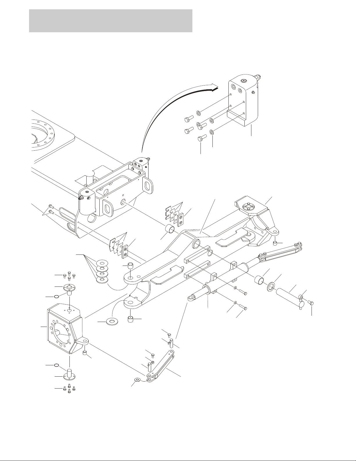
FIGURE 1-1.AXLE AND STEERING INSTALLATION
1-2 340AJ 3121260
Page 9

SECTION 1 FRAME
FIGURE 1-1. AXLE AND STEERING INSTALLATION
ITEM # PART NUMBER QTY. DESCRIPTION REV.
1001115772 Ref OSCILLATING AXLE INSTALLATION B
1 0100011 AR Compound, Locking
2 0761014 8 Bolt M10 x 30mm
3 0761614 1 Bolt M16 x 30mm
4 0961950 2 Bushing
5 3422592 1 Pin, Axle Pivot
6 3841258 1 Keeper, Pin
7 4740158 1 Thrustwasher
8 5241000 8 Flatwasher 10mm Hardened
9 5251012 4 Bolt, Flanged M10 x 25mm
10 1001116361 2 Lockout Cylinder Assembly (See Section 5 for Breakdown)
11 1001117869 1 Axle Weldment
12 1001118511 2 Pad, Wear
13 1001118518 2 Shim 11Ga.
14 1001118519 4 Shim 16Ga.
1001115771 Ref STEERING INSTALLATION A
101 0100011 AR Compound, Locking
102 0440271 2 Thrustwasher .250
103 0440274 2 Bearing
104 0440291 2 Bearing
105 0701220 4 Bolt M12 x 60mm
106 0761610 20 Bolt M16 x 20mm
107 0962140 2 Bushing
108 3020029 AR Grease, Bearing (Not Shown)
109 3423081 4 Kingpin
110 3780182 2 O-Ring
111 3841520 1 Keeper, Pin
112 4740086 2 Thrustwasher .0625
113 4740537 2 Thrustwasher .625
114 4740538 2 Thrustwasher .125
115 4740539 2 Thrustwasher .188
116 4740540 2 Thrustwasher .250
117 4812100 4 Flatwasher 12mm
118 1001116788 1 Steer Cylinder Assembly (See Section 5 for Breakdown):
119 1001116867 4 Pin, Pivot
120 1001116871 2 Link, Tie-Rod
121 1001117142 2 Spindle
3121260 340AJ 1-3
Page 10
SECTION 1 FRAME
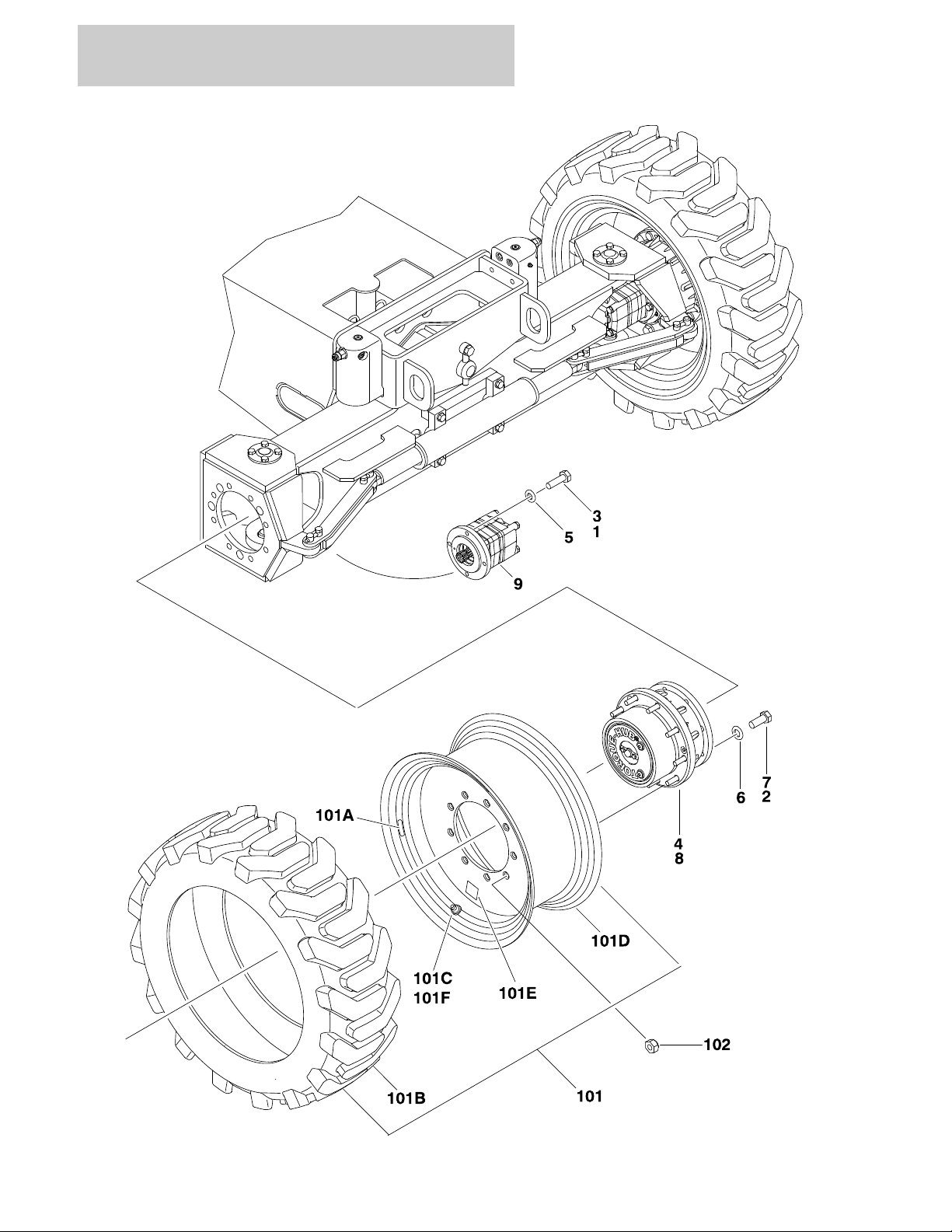
FIGURE 1-2. TIRE AND WHEEL DRIVE INSTALLATION
1-4 340AJ 3121260
Page 11

SECTION 1 FRAME
FIGURE 1-2. TIRE AND WHEEL DRIVE INSTALLATION
ITEM # PART NUMBER QTY. DESCRIPTION REV.
0275853 Ref WHEEL DRIVE INSTALLATION A
1 0100011 AR Compound, Locking
2 0100019 AR Compound, Locking
3 0761015 16 Bolt M10 x 35mm
4 3020008 .8 gal Lube HD80W-90
5 5241000 16 Flatwasher 10mm Hardened
6 5241600 32 Flatwasher 16mm Hardened
7 1001110922 32 Bolt M16 x 40mm Grade 10.9
8 1001116793 4 Drive Hub/Brake Assembly (See Drive Hub/Brake Assembly For
Breakdown)
9 1001117030 4 Drive Motor Assembly (See Drive Motor Assembly for Breakdown)
101 Ref TIRE AND WHEEL INSTALLATIONS
Ref Note: Due to Critical Stability Weights, only replace tire and
wheel assemblies with like components.
1001118641 Ref 7 x 18 Solid (Available on All Specs) B
1001118644 Ref 7 x 18 Solid Non-Marking (Available on All Specs) B
1001118640 Ref 9 x 20 Pneumatic (Available on ANSI, ANSI Export, CSA &
Japanese Specs)
1001120027/
1001120019
1001118643 Ref 9 x 20 Pneumatic Non-Marking (Available on ANSI, ANSI
1001120036/
1001120035
1001115773 Ref 9 x 20 Foam-Filled (Available on All Specs) A
1001118642 Ref 9 x 20 Foam-Filled Non-Marking (Available on ANSI, ANSI
Ref 9 x 20 Pneumatic with Tire Sealant (Available on ANSI Specs) A
Export, CSA & Japanese Specs)
Ref 9 x 20 Pneumatic Non-Marking with Tire Sealant (Available on
ANSI Specs)
Export, CSA & Japanese Specs)
A
A
A
A
1001118649 2 7 x 18 Solid Right Side B
1001121678 2 7 x 18 Solid Left Side A
1001118654 2 7 x 18 Solid Non-Marking Right Side A
1001121672 2 7 x 18 Solid Non-Marking Left Side A
1001118647 2 9 x 20 Pneumatic Right Side A
1001118648 2 9 x 20 Pneumatic Left Side A
1001118652 2 9 x 20 Pneumatic Non-Marking Right Side A
1001118653 2 9 x 20 Pneumatic Non-Marking Left Side A
1001117132 2 9 x 20 Foam-Filled Right Side A
1001117131 2 9 x 20 Foam-Filled Left Side A
1001118650 2 9 x 20 Foam-Filled Non-Marking Right Side A
1001118651 2 9 x 20 Foam-Filled Non-Marking Left Side A
Ref Note: Assemblies may require ballast/foam filling to
manufacture’s specifications prior to installing on a
machine. Refer to Operation & Safety or Service &
Maintenance Manuals. Purchase individual tire and/or rim
only if able to foam fill tire & wheel assembly, otherwise,
purchase complete assembly.
101A 1706846 1 Decal - 75PSI (Pneumatic Only):
3121260 340AJ 1-5
Page 12

SECTION 1 FRAME
FIGURE 1-2. TIRE AND WHEEL DRIVE INSTALLATION (CONTINUED)
ITEM # PART NUMBER QTY. DESCRIPTION REV.
101B 1 Tire Options:
See Note 7 x 18 Solid & Solid Non-Marking
(Note: Purchase Complete Assembly)
4520605 IN265/50D20
1001118660 IN265/50D20 Non-Marking
101C 4640113 1 Valve Stem, Air (Pneumatic Only)
101D 1 Rim, Wheel Options:
See Note 7 x 18 Solid & Solid Non-Marking
(Note: Purchase Complete Assembly)
1001117129 20 x 9 (Use with IN265/50D20 Tires)
101E 2902203 1 Decal Kit - Required on Tires with Sealant (Includes qty 5
Decals & qty 4 Green Valve Stem Caps)
101F 1120552 1 Cap, Valve Stem (Green) ( Tires with Sealant Only)
102 3300106 36 Lugnut (9 per wheel)
1-6 340AJ 3121260
Page 13

SECTION 1 FRAME
FIGURE 1-2. TIRE AND WHEEL DRIVE INSTALLATION (CONTINUED)
ITEM # PART NUMBER QTY. DESCRIPTION REV.
3121260 340AJ 1-7
Page 14
SECTION 1 FRAME
323130
29
28
26
25
24
23
22
20
19
19
19
16
17
13
14
18
27
34
35
39
FIGURE 1-3. DRIVE MOTOR ASSEMBLY
1-8 340AJ 3121260
Page 15

SECTION 1 FRAME
FIGURE 1-3. DRIVE MOTOR ASSEMBLY
ITEM # PART NUMBER QTY. DESCRIPTION REV.
1001117030 Ref DRIVE MOTOR ASSEMBLY B
1 to 12 Not Used
13 70003005 1 Plug
14 8007941 1 Washer
15 Not Used
16 See Note 1 Flange (Note: Not Available - Purchase p/n 1001117030)
17 70003006 1 O-RIng
18 70003007 1 Shaft
19 70003008 3 O-Ring
20 70003009 1 Gear Set
21 Not Used
22 70003010 1 Shaft, Coupling
23 70003011 1 Plate, Port
24 70003012 1 Ring, Stop
25 7027955 1 Disc, Valve
26 7027956 1 Plate, Pressure
27 7027957 1 Pin, Spring
28 70003013 1 O-Ring
29 70003014 1 O-Ring
30 7027958 1 Spacer
31 7027959 1 Washer, Crinkle
32 See Note 1 Cover, End (Note: Not Available - Purchase p/n 1001117030)
33 Not Used
34 70003016 4 Screw
35 80334555 2 Ball
36 to 38 Not Used
39 See Note 1 Nameplate (Note: Not Available for Purchase)
3121260 340AJ 1-9
Page 16
SECTION 1 FRAME
12
22
8A
1N
1K
8C
8B
1L
7
1M
5
8M
8L
8F
8H
8D
8E
8J
8K
18
176G1196E6D6B6K24H4G
4E
4B
4C1H
4F
1E
1G
1F
1D1B1A
6A
6C
1C
4D
6F
15
16
101
102
103
104
FIGURE 1-4. DRIVE HUB/BRAKE ASSEMBLY
1-10 340AJ 3121260
Page 17

SECTION 1 FRAME
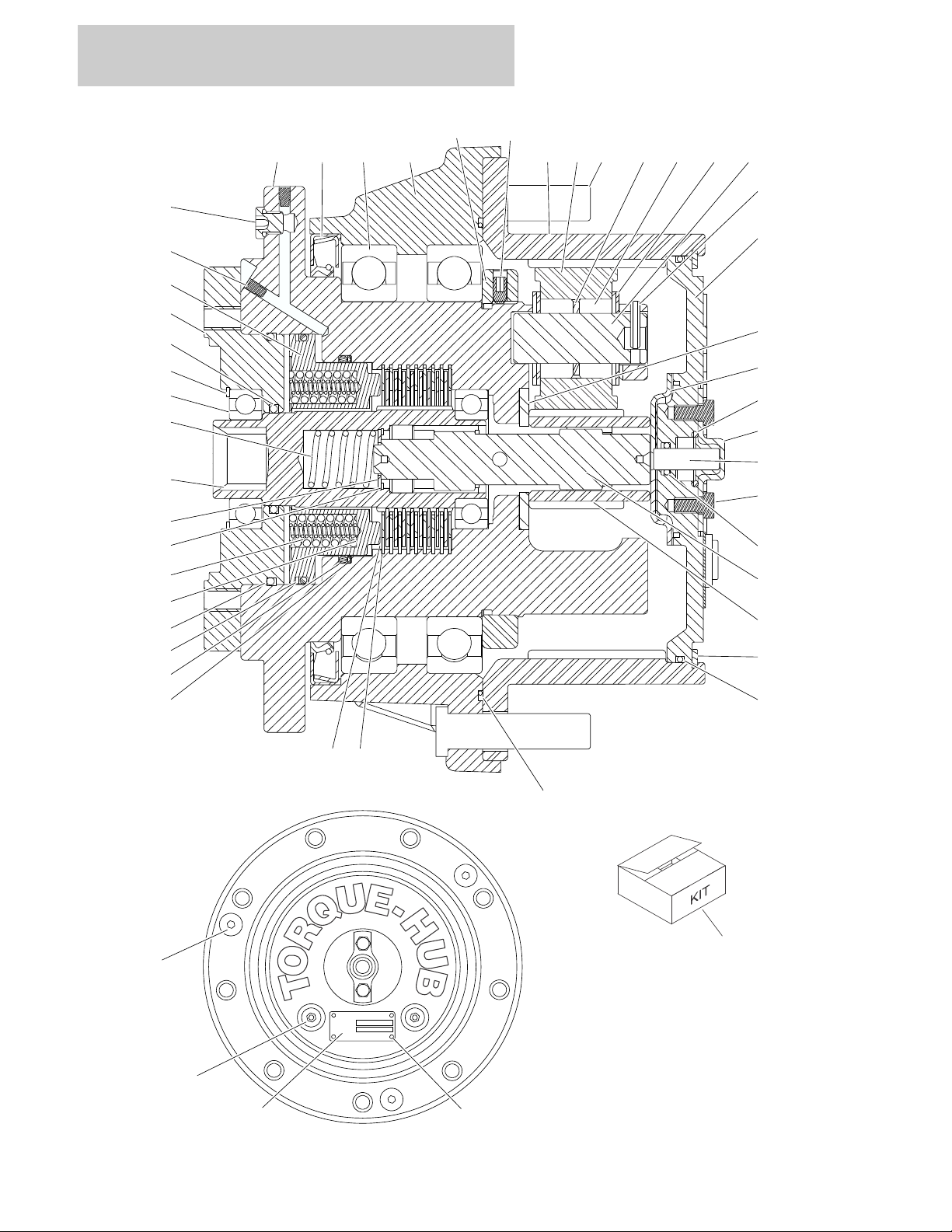
FIGURE 1-4. DRIVE HUB/BRAKE ASSEMBLY
ITEM # PART NUMBER QTY. DESCRIPTION REV.
1001116793 Ref DRIVE HUB/BRAKE ASSEMBLY A
1 See Note 1 Spindle Assembly (Note: Not Available for Purchase
1A 70002987 1 Spindle
1B 70001119 1 Seal, Lip (Part of Item 104)
1C 70002991 2 Bearing, Ball
1D See Note 1 Housing (Note: Not Available for Purchase
1E 70002989 1 Ring Gear
1F 70003000 1 Nut, Bearing (Part of Item 104)
1G 70002996 2 Setscrew 1/4in-28NF x 1/2in (Part of Item 104)
1H 7007640 9 Bolt, Mounting
1J Not Used
1K See Note 1 Seal (Note: Use Item 102 or 103)
1L 70002992 1 Spring
1M 70002999 1 Thrustwasher
1N 70002988 1 Adapter
2 7024741 1 Spacer, Thrust
3Not Used
4 70002983 1 Planet Gear Assembly (Includes Items 4B-4G)
4A Not Used
4B Use 70002983 12 Spacer, Washer (Note: Not Available for Purchase)
4C Use 70002983 AR Bearing (Note: Not Available for Purchase)
4D Use 70002983 3 Spacer (Note: Not Available for Purchase)
4E Use 70002983 3 Shaft, Planet (Note: Not Available for Purchase)
4F Use 70002983 1 Gear, Planet (Note: Not Available for Purchase)
4G 7001913 3 Rollpin
4H 7024742 1 Spacer, Thrust
5 70002995 1 Ring, Retaining
6 70001368 1 Cover Assembly (Includes Items 6A-F & 6K)
6A Use 70001368 1 Cover (Note: Not Available for Purchase)
6B Use 70001368 1 Cap (Note: Not Available for Purchase)
6C Use 70001368 2 Bolt (Note: Not Available for Purchase)
6D Use 70001368 1 Pin (Note: Not Available for Purchase)
6E Use 70001368 1 Washer Seal (Note: Not Available for Purchase)
6F Use 70001368 2 Plug (Note: Not Available for Purchase)
6G 7024738 1 Ring, Retaining
6H- 6J Not Used
6K Use 70001368 1 Retainer (Note: Not Available for Purchase)
7 70002985 1 Coupling
8 See Note 1 Brake Assembly (Includes Items 8A-8M)
(Note: Not Available as an Assembly)
8A 70002993 1 Piston, Brake
8B 70002990 2 Bearing, Ball
8C 70002994 1 Ring, Retaining
8D Use 70002981 1 O-Ring
8E Use 70002981 1 Ring, Back-up
8F See Note 2 O-Ring (Note: Use Item 102 or 103)
8G Not Used
8H Use 70002981 1 Ring, Back-up
3121260 340AJ 1-11
Page 18

SECTION 1 FRAME
FIGURE 1-4. DRIVE HUB/BRAKE ASSEMBLY (CONTINUED)
ITEM # PART NUMBER QTY. DESCRIPTION REV.
8J Use 70002980 8 Disc, Brake Reaction
8K Use 70002980 9 Disc, Brake Friction
8L Use 70002982 12 Spring
8M Use 70002982 12 Spring
9 70002984 1 Shaft, Input
10 Not Used
11 70002986 1 Gear, Sun
12 70002998 1 Plug, Pipe
13 to 14 Not Used
15 See Note 1 Nameplate (Note: Not Available for Purchase)
16 7000281 2 Drivescrew
17 7024134 1 O-RIng (Part of Item 104)
18 70002997 1 O-Ring (Part of Item 104)
19 7017022 3 Capscrew 3/8in-16NC (Part of Item 104)
20 Not Used
21 See Note 8 Capscrew 3/8in-16NC x 7/8in Grade 8 (Note: Use Item 102 or
103)
22 7024108 2 Plug, Pressure
— — — — — — — — — —
101 70002980 1 Brake Disc Kit (Includes Items 8J & 8K)
102 70002982 1 Brake Spring Kit (Includes Items 1K, 8F, 8L, 8M & 21)
103 70002981 1 Brake Seal Kit (Includes Item 1K, 8D, 8E, 8F, 8H & 21)
104 7024744 1 Hub Seal Kit (Includes Item 1B, 1F, 1G & 17-19)
1-12 340AJ 3121260
Page 19

SECTION 1 FRAME
FIGURE 1-4. DRIVE HUB/BRAKE ASSEMBLY (CONTINUED)
ITEM # PART NUMBER QTY. DESCRIPTION REV.
3121260 340AJ 1-13
Page 20
SECTION 1 FRAME
203
203
204
202
206
205
202
206
1
7
13
101
109
113
116
102
110
101
110
116
111
108
103
108
105
106
106
115
114
116
107
104
112
116
115
106
105
FIGURE 1-5.DRIVE VALVES AND FRAME SHIELDS INSTALLATIONS
1-14 340AJ 3121260
Page 21

SECTION 1 FRAME
FIGURE 1-5. DRIVE VALVES AND FRAME SHIELDS INSTALLATIONS
ITEM # PART NUMBER QTY. DESCRIPTION REV.
1001115780 Ref DRIVE VALVES INSTALLATION E
1 0100011 AR Compound, Locking
2 to 6 Not Used
7 5251010 4 Bolt M10 x 20mm
8 to 12 Not Used
13 1001118029 1 Flow Divider Valve Assembly (See Items 101-116 for Breakdown)
1001118029 Ref FLOW DIVIDER VALVE ASSEMBLY D
101 7012941 3 Valve, Solenoid Cartridge (without Coil) (Traction, Brake &
Secondary Oscillating)
7010543 3 Seal Kit - 7012941 Cartridge
102 70002955 1 Valve, Solenoid Cartridge (without Coil) (Primary Oscillating)
7012953 1 Seal Kit - 70002955 Cartridge
103 70002956 2 Valve, Solenoid Cartridge
70002957 2 Seal Kit - 70002956 Cartridge
104 700029568 1 Valve, Flow Divider Cartridge
70002959 1 Seal Kit - 70002958 Cartridge
105 70002960 1 Valve, Flow Divider Cartridge
70002978 1 Seal Kit - 70002960 Cartridge
106 70002961 4 Valve, Check Cartridge
7017496 4 Seal Kit - 70002961 Check Cartridge
107 70002962 1 Lock Kit
108 70000781 2 Lock Kit
109 70002386 2 Coil
110 70002963 2 Coil
111 See Note 2 Orifice .031 (Note: Not Available for Purchase)
112 See Note 1 Orifice .025 (Note: Not Available for Purchase)
113 See Note 1 Orifice .040 (Note: Not Available for Purchase)
114 70002063 1 Orifice .062
115 7024844 4 Plug
116 7017406 5 Plug
1001115781 Ref FRAME SHIELDS INSTALLATION C
201 Not Used
202 5250810 6 Bolt, Flange M8 x 20mm
203 1001118274 4 Nut, Clip M8
204 1001118915 2 Cover, Frame (Side)
205 1001118916 1 Cover, Frame (Top)
206 0100011 AR Compound, Locking
3121260 340AJ 1-15
Page 22

SECTION 1 FRAME
FIGURE 1-5. DRIVE VALVES AND FRAME SHIELDS INSTALLATIONS (CONTINUED)
ITEM # PART NUMBER QTY. DESCRIPTION REV.
1-16 340AJ 3121260
Page 23

SECTION 2
TURNTABLE
3121260 340AJ 2-1
Page 24

SECTION 2 TURNTABLE
26
24
24
102
19
11
3
1
5
1
2
8
22
252321
197
200
198
198
195
20
20
1
1
132
101
15
16
FIGURE 2-1.CONTROL VALVE & CHARGE FILTER INSTALLATION
2-2 340AJ 3121260
Page 25

SECTION 2 TURNTABLE
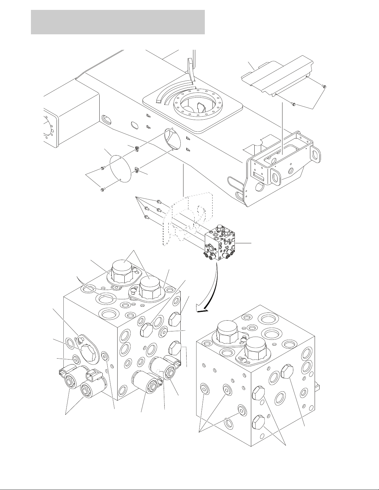
FIGURE 2-1. CONTROL VALVE & CHARGE FILTER INSTALLATION
ITEM # PART NUMBER QTY. DESCRIPTION REV.
1001115780 Ref VALVES INSTALLATION G
1 0100011 AR Compound, Locking
2 0641605 4 Bolt 3/8in-16NC x 5/8in
3 4811902 4 Flatwasher 8mm
4Not Used
5 5250810 10 Bolt, Flange M8 x 20mm
6 to 7 Not Used
8 1001102987 1 Charge Pump Filter Assembly C
70010383 1 Element, Filter (Includes O-Ring)
See Note 1 Indicator (Note: Not Available for Purchase)
9 to 10 Not Used
11 1001116487 1 Main Control Valve Assembly (See Main Control Valve Assembly
for Breakdown)
12 to 14 Not Used
15 0761014 2 Bolt M10 x 30mm
16 3291005 2 Locknut M10
17 to 18 Not Used
19 1001118751 1 Bracket, Filter
20 0700617 2 Bolt M8 x 16mm
21 1380136 1 Clip
22 2560122 1 Handle
23 3820122 2 Rivet
24 4811700 2 Flatwasher M6
25 1001114761 1 Grip, Handle
26 1001127115 1 Manual Pump Assembly A
7017496 1 Seal Kit - 1001127115 Pump
Ref HYDRAULIC INSTALLATION
1001115785 Ref Machines without Arctic Package F
1001120430 Ref Machines with Arctic Package D
101 0761012 1 Bolt M10 x 25mm
102 1321716 1 Clamp
103 to 131 Not Used
132 3291005 1 Locknut M10
133 to 194 Not Used
195 0700510 1 Bolt M5 x 20mm
196 Not Used
197 3290605 1 Locknut M6
198 4811700 1 Flatwasher M6
199 Not Used
200 85941016 1 Clamp
3121260 340AJ 2-3
Page 26
SECTION 2 TURNTABLE
FIGURE 2-2.MAIN CONTROL VALVE ASSEMBLY
2-4 340AJ 3121260
Page 27

SECTION 2 TURNTABLE
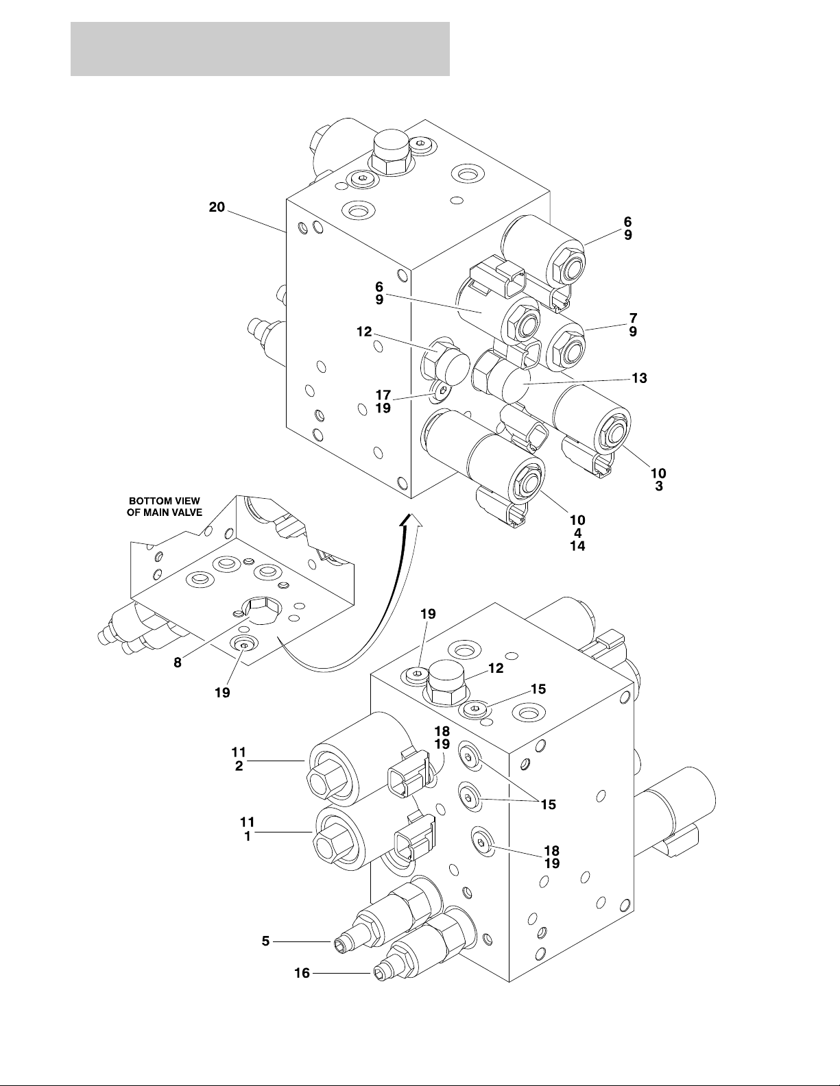
FIGURE 2-2. MAIN CONTROL VALVE ASSEMBLY
ITEM # PART NUMBER QTY. DESCRIPTION REV.
1001116487 Ref MAIN VALVE ASSEMBLY H
1 70002964 1 Cartridge, Solenoid Valve with Relief (without Coil)
7017496 1 Seal Kit - 7002964 Cartridge
2 70002965 1 Cartridge, Solenoid Valve with Relief (without Coil)
7017496 1 Seal Kit - 70002965 Cartridge
3 70002966 1 Cartridge, Solenoid Valve (without Coil) (Swing)
70002967 1 Seal Kit - 70002966 Cartridge
4 70002966 1 Cartridge, Solenoid Valve (without Coil) (Steer)
70002967 1 Seal Kit - 70002966 Cartridge
5 70002968 1 Cartridge, Relief Valve
7012998 1 Seal Kit - 70002968 Cartridge
6 70002969 2 Cartridge, Solenoid Valve (without Coil) (Upper & Lower Lift)
7010543 2 Seal Kit - Cartridge
7 70002970 1 Cartridge, Solenoid Valve (without Coil) (Flow Control)
7010543 1 Seal Kit - 70002970 Cartridge
8 10837580 1 Cartridge, Shuttle Valve
7010543 1 Seal Kit - 108377580 Cartridge
9 70002971 3 Coil
10 4 Coil Options:
7024885 Prior to SN 0300158122
70002386 SN 0300158122 to Present
11 2 Coil Options:
7024883 Prior to SN 0300158122
70003788 SN 0300158122 to Present
12 70002972 2 Cartridge, Pressure Compensator Valve
7010543 2 Seal Kit - 70002972 Cartridge
13 70002973 1 Cartridge, Pressure Compensator Valve
7010543 1 Seal Kit - 70002973 Cartridge
14 70002974 1 Disc, Check Valve
15 70003757 3 Cartridge, Check Valve (was p/n 70002975)
70002976 3 Seal Kit - 70002975 & 70003757 Cartridges
16 70002977 1 Cartridge, Crossover Relief
7021653 1 Seal Kit - 70002977 Cartridge
17 See Note 1 Orifice .060 (Note: Not Available for Purchase)
18 See Note 2 Orifice .100 (Note: Not Available for Purchase)
19 7017406 5 Plug
20 See Note 1 Block (Note: Not Available for Purchase)
3121260 340AJ 2-5
Page 28
SECTION 2 TURNTABLE
FIGURE 2-3.TURNTABLE AND SWING DRIVE INSTALLATIONS
2-6 340AJ 3121260
Page 29

SECTION 2 TURNTABLE
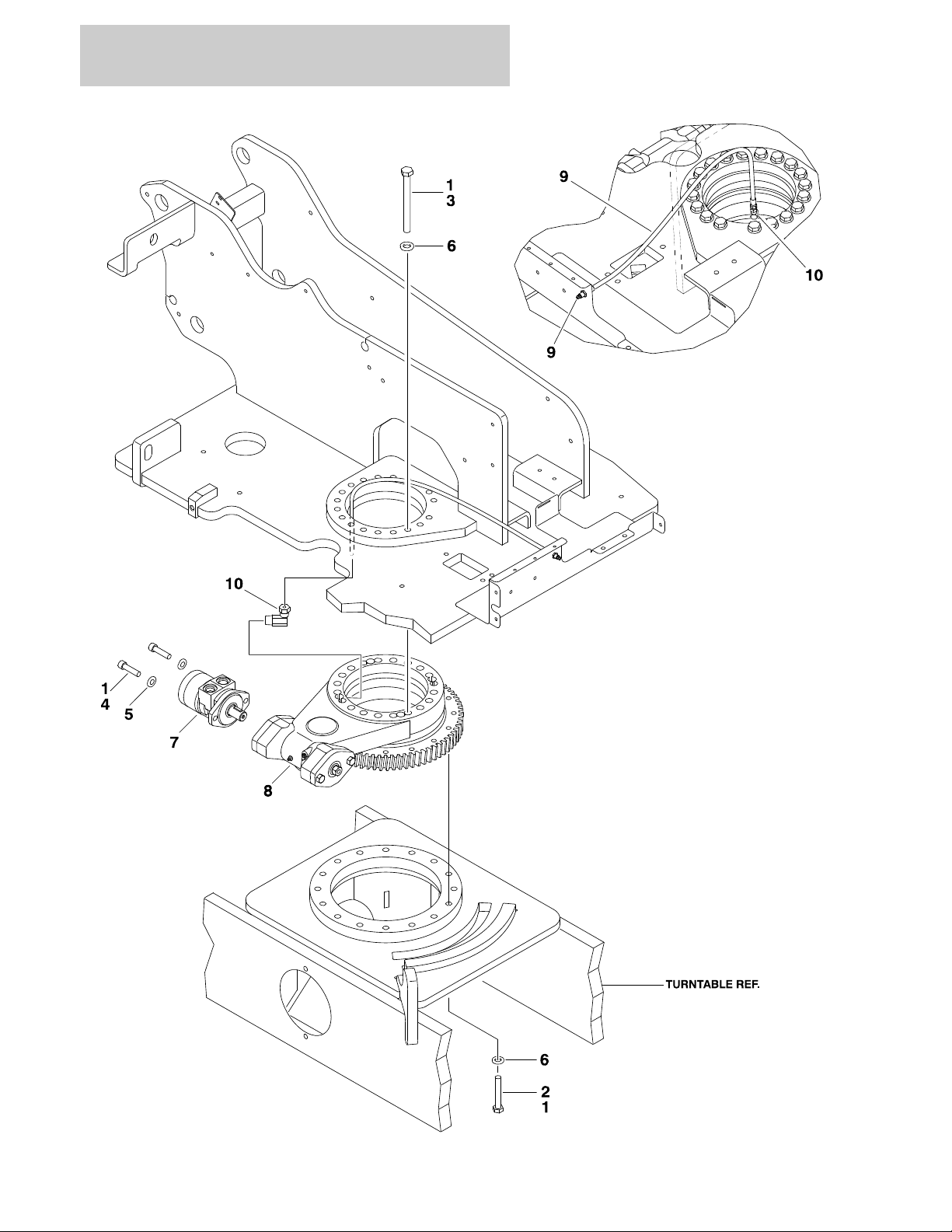
FIGURE 2-3. TURNTABLE AND SWING DRIVE INSTALLATIONS
ITEM # PART NUMBER QTY. DESCRIPTION REV.
Ref TURNTABLE BEARING & SWING DRIVE INSTALLATIONS
1001115774 Ref Turntable Bearing & Swing Drive (DOHI) C
1001153364 Ref Turntable Bearing & Swing Drive (JING WEI) B
1 0100019 AR Compound, Locking
2 0711426 16 Bolt M14 x 90mm (Grade 10.9)
3 0711432 19 Bolt M14 x 150mm (Grade 10.9)
4 3931832 2 Capscrew 1/2in-13NC x 2in
5 4740171 2 Flatwasher 1/2in Hardened
6 5241400 2 Flatwasher 14mm Hardened
7 1001107781 1 Swing Motor Assembly (See Swing Motor Assembly for Break-
down)
8 1 Swing Bearing and Rotation Box Assembly Options (See Turn-
table Bearing Assembly for Breakdown):
1001117145 DOHI
1001153015 JING WEI
9 1001118961 1 Hose, Remote Grease Line (Includes Grease Fitting)
10 1 Fitting, Swivel Adapter Options:
2220063 Prior to SN 0300176416
2220124 SN 0300176416 to Present
3121260 340AJ 2-7
Page 30
SECTION 2 TURNTABLE
8
1
2
3
9
4
4
4
4
4
5
7
6
10
13
14
14
15
16
25
17
18
19
20
12
100
FIGURE 2-4. SWING MOTOR ASSEMBLY
2-8 340AJ 3121260
Page 31

SECTION 2 TURNTABLE
FIGURE 2-4. SWING MOTOR ASSEMBLY
ITEM # PART NUMBER QTY. DESCRIPTION REV.
1001107781 Ref SWING MOTOR ASSEMBLY (PARKER) A
1 70002311 5 Bolt
2 7004035 1 Cover, End
3 Use 7024389 1 Seal, Commutator
4 Use 7024389 5 Seal, Ring
5 7024453 1 Commutator and Ring Assembly
6 Use 7024453 1 Ring
7 7024379 1 Manifold
8 70002312 1 Rotor Set
9 7024380 1 Plate, Wear
10 70002313 1 Link, Drive
11 Not Used
12 70000088 1 Shaft, Coupling
70000089 1 Key, Woodruff
13 7024381 1 Bushing, Bronze
14 7004043 2 Washer, Thrust
15 7004044 1 Bearing, Thrust
16 Use 7024389 1 Seal, Inner
17 Use 7024389 1 Washer, Back-up
18 Use 1001107781 1 Housing (Note: Not Available for Purchase)
19 7024390 1 Bearing
20 Use 7024389 1 Seal
21 to 24 Not Used
25 Use 7024389 1 Washer, Backup
— — — — — — — — — —
100 7024389 1 Seal Kit (Includes Items 3, 4, 16,17, 20 & 25)
3121260 340AJ 2-9
Page 32

SECTION 2 TURNTABLE
17411
18
2726151621
19233030243110223
6322
12
8
14
25
13
1
5
9
28
29
20
7
FIGURE 2-5. TURNTABLE BEARING ASSEMBLY
2-10 340AJ 3121260
Page 33

SECTION 2 TURNTABLE
FIGURE 2-5. TURNTABLE BEARING ASSEMBLY
ITEM # PART NUMBER QTY. DESCRIPTION REV.
Ref TURNTABLE BEARING ASSEMBLIES
1001117145 Ref Turntable Bearing (DOHI) D
1001153015 Ref Turntable Bearing (JING WEI) B
1 7026041 2 Flatwasher 5/16in Hardened
2 70002643 2 Cup, Bearing
70002644 2 Cone, Bearing
3 70002645 1 Seal
4 70002646 8 Bolt 5/16in-18NC x 7/8in
5 70003138 2 Bolt 5/16in-18NC x 2-1/2in
6 70002647 2 Bolt 1/2in-13NC x 1in
7 70002648 2 Bolt 1/2in-13NC x 1-1/4in
8 70002649 1 Vent, Pressure
9 70002650 1 Seal
10 70003139 1 Plug 1/4in
11 70002651 1 Fitting, Grease 1/4in
12 70002652 1 Fitting, Grease 1/8in Straight
13 7027359 1 Fitting, Grease 1/8in Elbow
14 Use 1001143932 1 Ring Gear Kit (Kit Includes Ring Gear & Mounting Hardware)
(was p/n 70003140)
15 70002656 1 Cup, Bearing
70002657 1 Cone, Bearing
16 70002658 1 Ring, Grease
17 7026048 1 Cup, Bearing
7026049 1 Cone, Bearing
18 70002659 1 Cap, Gear
19 70003141 1 Plate, Cover
20 70002661 1 Cap, Worm
21 70003142 1 Pinion, Output
22 70002663 1 Adapter, Motor
23 70002664 1 Seal, Face
24 7026052 1 Spacer, Washer
25 Use 1001117145 1 Housing (Note: Not Available for Purchase)
26 70002665 1 Shim .0075 Natural
70002666 1 Shim .005 Blue
70002667 1 Shim .003 Green
27 70002668 1 Shim .005 Blue
70002669 1 Shim .020 Yellow
28 7027352 1 Gasket .010 Brown
7027351 1 Gasket .0075 Clear
7027350 1 Gasket .005 Blue
29 7027353 1 Gasket .020 Yellow
30 70000681 10 Bolt, Flange #6-32NC x 3/8in
31 70002670 1 Gear, Worm
32 70002671 1 Shaft, Worm
3121260 340AJ 2-11
Page 34

SECTION 2 TURNTABLE
33
34
31
31
31
247
272
11
251
213
213
265
242
231
269
254
253
208
233
233
239
220
261
224
215
236
232
219
232
223
218
211
234
213
213
250
201
205
232
248
249
234
201
262
207
235
203
234
234
228
252
201
263
267
233
234
268
252615
5
29
273
274
201
209
201
209
271
217
234
234
222
271
237
233248
224
204
230
SEE NOTE
#240
238
221
22914226
257
234
285
234
206
226
277
288
287
289
284
289
288
223
232
289
288
223
232
223
279
278
286
280
36
35
32
30
30
30
30
278
260
260
281
283
280
25617131722
FIGURE 2-6.GM ENGINE INSTALLATION
2-12 340AJ 3121260
Page 35

SECTION 2 TURNTABLE
234
234
269
242
255
241
240
106
108
105
FOR BATTERY:
SEE ELECTRICAL
COMPONENTS
INSTALLATION
CONNECT ITEM 23 TO
GM ENGINE HARNESS
SUPPLIED
THIS ASSEMBLY SHOWN HERE FOR CLARITY
102
104
103
101
240D
240A
20
240C
NOTE: SEE GM
ENGINE SUPPLEMENT
P/N 3121245 FOR DETAILED
ENGINE BREAKDOWN.
ENGINE
MOUNT REF.
226
259
270
211
216
216
258
224
233
233
201
208
202
214
262
201
207
235
203
231
227
234
234
228
27
16
206
234
234
226
246
217
208
233
3
3
266
266
276
22347
41
43
181897712240B
19
SUPPLY
RETURN
3728293831
40
1
7
10
1
7
10
3121260 340AJ 2-13
Page 36

SECTION 2 TURNTABLE
FIGURE 2-6. GM ENGINE INSTALLATION
ITEM # PART NUMBER QTY. DESCRIPTION REV.
Ref Note: ANSI, ANSI Export, CSA & Japanese Specs Only.
Arctic Machines NOT Available in Japanese Spec.
Ref GM ENGINE INSTALLATION
1001117975 Ref Machines without Arctic Package H
1001120248 Ref Machines with Arctic Package G
1 0100020 AR Sealant, Pipe
2 0100048 AR Grease, Dielectric
3 0100051 AR Grease, Battery Terminal
4 Not Used
5 0761016 2 Bolt M10 x 40mm
6 Not Used
7 1320022 8 Clamp, Fuel Line
8 1320026 1 Clamp, Muffler
9 1320318 1 Clamp, Double-P
10 2180348 2 Fitting, Barbed
11 2.4gal/9L Coolant
2300004 Machines without Arctic Package
2300041 Machines with Arctic Package
12 2720566 1 Hose (6in/15cm Length)
13 3291605 1 Locknut M16
14 3960464
15 4812000 2 Flatwasher 10mm
16 4812100 1 Flatwasher 12mm
17 4812500 2 Flatwasher 20mm
18 1001091587
19 1001097588 3 Clip, Tube
20 3.2qts/3L Oil, Engine
1001115930 Machines without Arctic Package (10W-30)
1001115931 Machines with Arctic Package (5W-30)
21 Not Used
22 1001118646 1 Bolt, Shoulder M20 x 80mm
23 1001119778 1 Harness, Fuel Pump (See Section 7 for Breakdown)
24 1001119902 1 Pipe, Exhaust
25 1001120087 1 Pad, Wear
26 1001120090 2 Shim 1.5mm
27 0761214 1 Bolt M12 x 30mm
28 5251012 3 Bolt, Flange M10 x 25mm
29 0100011 AR Compound, Locking
30 0760606 7 Bolt M6 x 12mm
31 3290605 7 Locknut M6
32 1001128801 1 Canister, Carbon
33 1001128931 1 Bracket, Mounting
34 1001128936 1 Ring
35 1001129255 7in/17cm Hose
36 1001129256
37 4240033 AR Tie-Strap
38 0760612 17 Bolt M6 x 25mm
33in/84cm
7.2ft/2.18m
9.5ft/2.85m
Seal
Hose, Fuel Line
Hose
2-14 340AJ 3121260
Page 37

SECTION 2 TURNTABLE
FIGURE 2-6. GM ENGINE INSTALLATION (CONTINUED)
ITEM # PART NUMBER QTY. DESCRIPTION REV.
39 Not Used
40 4740362 10 Flatwasher, Special
41 4811700 10 Flatwasher 6mm
42 Not Used
43 1001137367 1 Shield, Fuel Line
44 to 46 Not Used
47 1001137402 1 Shield, Rubber
1001117974 Ref GM ENGINE AND PUMP SUB-ASSEMBLY D
101 0641813 2 Bolt 1/2in-13NC x 1-5/8in
102 4891600 2 Flatwasher 3/8in Hardened
103 4891800 2 Flatwasher 1/2in Hardened
104 83191040 2 Capscrew, Socket Head M10 x 30mm
105 1001117028 1 Pump Assembly (See Axial Pump Assembly for Breakdown)
106 1001117029 1 Gear Pump Assembly (See Gear Pump Assembly for Breakdown)
107 Not Used
108 3790152 1 O-Ring
1001117973 Ref GM ENGINE ASSEMBLY O
201 0100011 AR Compound, Locking
202 0340045 2 Band, Mounting
203 0641609 8 Bolt 3/8in-16NC x 1-1/8in
204 0641807 2 Bolt 1/2in-13NC x 7/8in
205 0700621 4 Bolt M6 x 65mm
206 0701015 7 Bolt M10 x 35mm
207 0701221 4 Bolt M12 x 65mm
208 0760812 6 Bolt M8 x 25mm
209 0760814 AR Bolt M8 x 30mm
210 Not Used
211 0761014 8 Bolt M10 x 30mm
212 Not Used
213 1320012 4 Clamp
214 1320016 1 Clamp
215 1320022 3 Clamp
216 1321682 2 Clamp
217 1321716 2 Clamp, Double-P
218 1580011 1 Container, Coolant Overflow
219 2720058
220 2720271
221 2720615
222 3200378 2 Mount, Motor
223 3290605 17 Locknut M6
224 3290805 8 Locknut M8
225 Not Used
226 3291005 13 Locknut M10
227 3291205 4 Locknut M12
228 3311605 8 Locknut 3/8in-16NC
18in/46cm
19in/47cm
6.5in/17cm
Hose
Hose
Hose
3121260 340AJ 2-15
Page 38

SECTION 2 TURNTABLE
FIGURE 2-6. GM ENGINE INSTALLATION (CONTINUED)
ITEM # PART NUMBER QTY. DESCRIPTION REV.
229 3960464
230 4711800 2 Flatwasher 1/2in Narrow
231 4740274 4 Flatwasher, Snubbing
232 4811700 13 Flatwasher M6
233 4811900 18 Flatwasher M8
234 4812000 48 Flatwasher M10
235 4812100 4 Flatwasher M12
236 5250608 4 Bolt, Flange M6 x 16mm
237 5250812 4 Bolt, Flange M8 x 25mm
238 8405006 1 Clamp
239 85941016 1 Clamp
240 1001117892 1 Engine, GM.97L (See GM Engine Supplement P/N 3121245 for
240A 70002979 1 Filter, Oil
240B 7027972 1 Filter, Fuel
240C 70003178 1 Module, Control
240D 70003179 4 Plug, Spark
241 1001118280 1 Air Filter Assembly A
7015004 1 Element, Air Filter
1340069 1 Valve, Vacuum
7015005 1 Cover
242 1001118453 1 Tray, Engine
243 to 245 Not Used
246 1001118746 1 Bolt M10 x 25mm
247 1001119494 1 Radiator
70002899 1 Cap, Radiator
248 1001119495 1 Fan
249 1001119496 1 Spacer, Fan
250 1001119635 1 Hose, Upper Radiator
251 1001119636 1 Hose, Lower Radiator
252 1001119640 1 Plate, Rear Engine
253 1001119641 1 Plate, LH Front Engine
254 1001119643 1 Spacer, Mounting
255 1001119644 1 Plate, RH Front Engine
256 1001119649 1 Mount, Radiator
257 1001119698 1 Gusset, Radiator
258 1001119699 1 Elbow, Air Intake
259 1001119700 1 Hose, Air Intake
260 1001119727 2 Clamp, Muffler
261 1001119730 1 Bracket, Coolant Overflow Tank
262 1001119929 4 Bolt M10 x 35mm
263 1001119930 2 Bolt M10 x 50mm
264 Not Used
265 1001119701 1 Bracket, Muffler Mounting
266 1001118594 1 Battery Cable Kit B
4461231 1 Battery Terminal & Red Cover Only (No Cable)
4461232 1 Battery Terminal & Black Cover Only (No Cable)
267 0760817 2 Bolt M8 x 45mm
268 1001120454 2 Housing, Spacer
269 3200425 2 Mount, Engine
6.5in/17cm
Seal
Breakdown of Additional Components)
2-16 340AJ 3121260
Page 39

SECTION 2 TURNTABLE
FIGURE 2-6. GM ENGINE INSTALLATION (CONTINUED)
ITEM # PART NUMBER QTY. DESCRIPTION REV.
270 80673025 1 P-Clamp
271 1320223 2 J-Clip
272 1703162 2 Decal - Fan Blade
273 1001120087 1 Pad, Wear
274 1001120090 3 Shim
275 Not Used
276 1001120450 1 Cable, Ground
277 0760610 6 Bolt M6 x 20mm
278 1001123016 1 Seal, Radiator Hood
279 1001123017 1 Plate, Seal Support
280 1001123018 1 Plate, Seal Support
281 1001137326 1 Insulate, Muffler
282 1001137327 1 Insulate, Muffler
283 1001137336 3 Strap
284 1001137398 1 Shield, Rubber
285 1001137399 1 Shield, Rubber
286 1001137371 1 Deflector
287 1001137400 1 Shield, Rubber
288 0760612 7 Bolt M6 x 25mm
289 4740362 7 Flatwasher, Special
3121260 340AJ 2-17
Page 40

SECTION 2 TURNTABLE
25
235
250
229
244
221
213
23621237
223
223
210
210
SUPPLIED
WITH
ENGINE
243
222
206
201
14
210
210
234
209
233
215
219
270
273
271
272
270
214
215
223
223
204
225
269
223
223
215
215
253
201
242
241
224
205
201
252
223
203
203
223
223
223
223
217
217
313223
23
7
7
8
24
2025266
265
256
212
TO
BATTERY
2
257
262
212
223
223
201
209
201
261
263
30
302
227
309
318
307
316
306
312
313
317
305
303
319
314
26
304
322
323
33
34
201
208
268
315
FIGURE 2-7.KUBOTA ENGINE INSTALLATION
2-18 340AJ 3121260
Page 41

320
245
29
229
17
13112112112115522222222191699999
9
16
FUEL TANK REF.
211
211
211
231
232
202
228
230410
18
203
203
223
223
223
223
213
217
221
205
224
201
252
201
252
223
223
223
216
256
260
3
256
260
3
FOR BATTERY:
SEE ELECTRICAL
COMPONENTS
INSTALLATION
201
208
SUPPLIED
WITH
ENGINE
264
264
246
11
28
247
308
201
220
227
106
108
105
103
101
248
TO
BATTERY
256
222
222
249
214
276
207
275
201
218
201
218
217
217
255
274
278
276
275
222
279
102
104
267
285
282
280
283
284
281
SECTION 2 TURNTABLE
3121260 340AJ 2-19
Page 42

SECTION 2 TURNTABLE
FIGURE 2-7. KUBOTA ENGINE INSTALLATION
ITEM # PART NUMBER QTY. DESCRIPTION REV.
Ref Note: Arctic Machines NOT Available on Australian, CE &
Japanese Spec.
Ref KUBOTA ENGINE INSTALLATION
1001115767 Ref Machines without Arctic Package G
1001117978 Ref Machines with Arctic Package G
1 0100020 AR Sealant, Pipe
2 0100048 AR Grease, Dielectric
3 0100051 AR Grease, Battery Terminal
4 0760608 4 Bolt M6 x 16mm
5 0760814 2 Bolt M8 x 30mm
6 Not Used
7 0761016 2 Bolt M8 x 40mm
8 0761214 1 Bolt M12 x 30mm
9 1320022 6 Clamp, Fuel Line
10 1320043 1 Clamp, Cable
11 1320274 1 Clamp, Muffler
12 2180348 3 Fitting, Barbed
13 2180666 1 Fitting, Barbed
14
2300004 Machines without Arctic Package
2300041 Machines with Arctic Package
15 2540045 1 Grommet
16 2720058 63in/1.6m Hose
17 2720271 68in/1.7m Hose
18 3290605 4 Locknut M6
19 3290805 2 Locknut M8
20 3291605 1 Locknut M16
21 3960464
22 4811900 4 Flatwasher 8mm
23 4812000 2 Flatwasher 10mm
24 4812100 1 Flatwasher 12mm
25 4812500 2 Flatwasher 20mm
26
1001115930 Machines without Arctic Package (10W-30)
1001115931 Machines with Arctic Package (5W-30)
27 Not Used
28 1001118548 1 Tube, Exhaust
29 1001118619 1 Fuel Filter/Water Separator Assembly
70002900 1 Filter, Fuel
70002901 1 Bowl Kit - Water Separator (Includes Bowl, Drain & Plug)
30 1001118646 1 Bolt, Shoulder M20 x 80mm
31 1001120087 1 Pad, Wear
32 1001120090 AR Shim 1.5mm
33 0100011 AR Compound, Locking
34 5251012 1 Bolt, Flanged M10 x 25mm
1.6gal/5.9L
33in/84cm
5.4qt/5.1L
Coolant
Seal
Oil, Engine
2-20 340AJ 3121260
Page 43

SECTION 2 TURNTABLE
FIGURE 2-7. KUBOTA ENGINE INSTALLATION (CONTINUED)
ITEM # PART NUMBER QTY. DESCRIPTION REV.
1001117977 Ref KUBOTA ENGINE AND PUMP SUB-ASSEMBLY E
101 0641813 2 Bolt 1/2in-13NC x 1-5/8in
102 4891600 2 Flatwasher 3/8in Hardened
103 4891800 2 Flatwasher 1/2in Hardened
104 83191040 2 Capscrew, Socket Head M10 x 30mm
105 1001117028 1 Pump Assembly (See Axial Pump Assembly for Breakdown)
106 1001117029 1 Gear Pump Assembly (See Gear Pump Assembly for Breakdown)
107 Not Used
108 3790152 1 O-Ring
1001117976 Ref KUBOTA ENGINE ASSEMBLY Q
201 0100011 AR Compound, Locking
202 0340045 1 Band, Mounting
203 0641609 8 Bolt 3/8in-16NC x 1-1/8in
204 0701015 6 Bolt M10 x 35mm
205 0701221 4 Bolt M12 x 65mm
206 0760607 2 Bolt M6 x 14mm
207 0760612 4 Bolt M6 x 25mm
208 0760815 3 Bolt M8 x 35mm
209 0761014 6 Bolt M10 x 30mm
210 1320012 4 Clamp
211 1321682 3 Clamp
212 1321716 2 Clamp, Double-P
213 1001120307 4 Mount, Motor
214 3290605 12 Locknut M6
215 3291005 12 Locknut M10
216 3291205 4 Locknut M12
217 3311605 8 Locknut 3/8in-16NC
218 3321402 2 Nut, Jam 1/4in-12NF
219 3960464
220 4031707 2 Capscrew M6 x 16mm
221 4740274 4 Flatwasher, Snubbing
222 4811700 10 Flatwasher M6
223 4812000 48 Flatwasher M10
224 4812100 4 Flatwasher M12
225 80673025 1 P-Clamp
226 85941016 1 Clamp
227 1001117848 1 Engine, Kubota D1105 (See Items 301-323 for Breakdown)
228 1001118280 1 Air Filter Assembly A
7015004 1 Element, Air Filter
1340069 1 Valve, Vacuum
7015005 1 Cover
229 1001118453 1 Tray, Engine
230 1001128214 1 Bracket, Air FIlter
231 1001118527 1 Hose, Air Intake
232 1001118528 1 Hose, Air Intake
233 1001118529 1 Hose, Lower Radiator
6.5in/17cm
Seal
3121260 340AJ 2-21
Page 44

SECTION 2 TURNTABLE
FIGURE 2-7. KUBOTA ENGINE INSTALLATION (CONTINUED)
ITEM # PART NUMBER QTY. DESCRIPTION REV.
234 1001118530 1 Hose, Upper Radiator
235 1001118531 1 Radiator
70002899 1 Cap, Radiator
236 1001118532 1 Mount, Radiator
237 1001119698 1 Gusset, Radiator
238 to 240 Not Used
241 1001118538 1 Fan
242 1001118539 1 Spacer, Fan
243 1001118540 1 Bracket, Coolant Overflow Tank
244 1001118542 1 Plate, LH Front Engine
245 1001118543 1 Plate, RH Front Engine
246 1 Muffler Options:
Use 1001151187 Standard (was p/n 1001118547)
Use 1001151188 Catalytic (was p/n 1001120007)
247 1001118579 1 Actuator, Kubota Governor
7023134 1 Gasket, Mounting
248 1001118580 1 Sensor, Speed
249 1001118582 1 Actuator, Kubota Throttle
250 1001118675 1 Flywheel Housing/Coupling Kit
See Note 1 Coupling Assembly (Note: Not Available for Purchase)
See Note 1 Housing (Note: Not Available for Purchase)
See Note 1 Bolt Kit (Note: Not Available for Purchase)
251 Not Used
252 1001118746 8 Bolt M10 x 25mm
253 1001118878 4 Bolt M6 x 55mm
254 Not Used
255 1001118881 1 Clevis, Actuator
256 1001118594 1 Battery Cable Kit
4461231 1 Battery Terminal & Red Cover Only (No Cable)
4461232 1 Battery Terminal & Black Cover Only (No Cable)
257 1001118638 1 Harness, Engine (See Section 7 for Breakdown)
258 to 259 Not Used
260 0100048 AR Grease, Dielectric
261 Not Used
262 1320223 2 J-Clip
263 1703162 2 Decal - Fan Blade
264 1001100825 2 Strap
265 1001120087 1 Pad, Wear
266 1001120090 3 Shim
267 1001121531 1 Insulation, Muffler
268 1001120450 1 Cable, Ground
269 0761018 1 Bolt M10 x 50mm
270 0760610 8 Bolt M6 x 20mm
271 1001123016 1 Seal, Radiator Hood
272 1001123017 1 Plate, Seal Support
273 1001123018 1 Plate, Seal Support
274 0440334
275 0641408 2 Bolt 1/4in-20NC x 1in
276 3311405 2 Locknut 1/4in-20NC
1
End, Rod with Bearing
2-22 340AJ 3121260
Page 45

SECTION 2 TURNTABLE
FIGURE 2-7. KUBOTA ENGINE INSTALLATION (CONTINUED)
ITEM # PART NUMBER QTY. DESCRIPTION REV.
277 4761400 2 Lockwasher 1/4in
278 1001118925 1 End, Rod with Bearing
279 1001128888 1 Spacer
280 0701017 1 Bolt M10x 45mm (SN 0300169182 to Present)
281 0760812 2 Bolt M8 x 25mm (SN 0300169182 to Present)
282 0760817 1 Bolt M8 x 45mm (SN 0300169182 to Present)
283 3290807 2 Locknut M8 x 1.25 (SN 0300169182 to Present)
284 4811900 2 Flatwasher 8mm (SN 0300169182 to Present)
285 1001149379 1 Bracket (SN 0300169182 to Present)
1001117848 Ref ENGINE COMPONENTS D
301 7017900 1 Valve, Drain (Not Shown - Located on Opposite of Engine)
302 7023132 1 Gasket, Valve Cover
303 70003060 1 Breather, Comp Valve
70003061 1 Cover, Breather
304 70002318 1 Plug, Oil Fill
70002193 1 O-Ring, Oil Fill Plug
305 7017923 1 Filter, Oil
306 7023160 1 Dipstick
70003062 1 Tube, Dipstick
307 70001934 1 Flywheel
70001140 1 Ring Gear
308 Use 1001118579 1 Solenoid, Stop (was p/n 7025479)
309 7023164 1 Pump, Fuel Injection
70002319 1 Shim .175mm
70002320 1 Shim .200mm
70002321 1 Shim .250mm
70002322 1 Shim .300mm
70002323 1 Shim .350mm
310 See Note 3 Nozzle, Fuel Injector (Note: Not Available for Purchase)
70002324 3 Plug, Glow (Includes Flanged Nut)
311 7023139 1 Pump, Fuel (Not Shown - Located on Opposite of Engine)
7017995 1 Gasket, Fuel Pump
312 7023169 1 Alternator
313 7023141 1 V-Belt
314 7023144 1 Starter
315 7017901 1 Switch, Oil
316 7023170 1 Thermostat
7023145 1 Gasket, Thermostat Housing to Hose Neck
70002326 1 Gasket, Thermostat Hosing to Engine Block
70003064 1 Sensor, Water Temperature
70003063 1 Seal, Water Temperature Sensor
317 70002327 1 Pump, Water
70002328 1 Gasket, Water Pump
318 See Note 1 Manifold, Air Intake (Note: Not Available for Purchase)
7023130 1 Gasket, Air Intake Manifold
319 See Note 1 Manifold, Exhaust (Note: Not Available for Purchase)
7023148 1 Gasket, Exhaust Manifold to Engine Block
3121260 340AJ 2-23
Page 46

SECTION 2 TURNTABLE
FIGURE 2-7. KUBOTA ENGINE INSTALLATION (CONTINUED)
ITEM # PART NUMBER QTY. DESCRIPTION REV.
320 7023124 1 Gasket, Exhaust Manifold to Muffler
321 7023152 1 Timer, Glow Plug (Not Shown)
322 70003066 1 Upper Gasket Kit (Includes Qty 1 Each of Cylinder Head, Valve
Cover, Intake Manifold to Block, Exhaust Manifold to Block,
Exhaust Manifold Gasket to Muffler, Thermostat Housing to Block,
Thermostat Housing to Neck Gaskets and Fuel System Seals &
O-Rings and Qty 6 Valve Stem Seals.)
323 70003067 1 Lower Gasket Kit (Includes Qty 1 of Gear Case, Bearing Case,
Case Cover, Fuel Pump, Water Pump Gaskets and Sensor Seals
& O-Rings and Qty 2 Oil Seals,)
2-24 340AJ 3121260
Page 47

SECTION 2 TURNTABLE
FIGURE 2-7. KUBOTA ENGINE INSTALLATION (CONTINUED)
ITEM # PART NUMBER QTY. DESCRIPTION REV.
3121260 340AJ 2-25
Page 48

SECTION 2 TURNTABLE
12
28
29
21
3A
3A
50
47
68
68
5863576246
467559
69
44
453849
48
4948414366
76676564777865
641415
39
1
4
37
27
27
25
73
24
23
22
26
19
16
71
71
16
17
17
20
18
18
36
36
35
35
33
33
2
2
2A
2A
3
3
30
30
31
31
72
72
51
52
53
54
55
567411
9
10
8
6770513
34
34
570717273747576100
FIGURE 2-8.AXIAL PUMP ASSEMBLY
2-26 340AJ 3121260
Page 49

SECTION 2 TURNTABLE
FIGURE 2-8. AXIAL PUMP ASSEMBLY
ITEM # PART NUMBER QTY. DESCRIPTION REV.
1001117028 Ref AXIAL PUMP ASSEMBLY D
1 70002132 2 Pin
2 70002133 2 Plug
2A Use 70002133 2 O-Ring
3 7007439 2 Plug
3A Use 7007439 2 O-Ring
4 70002134 2 Screen
5 70002135 1 Cylinder Block & Piston Kit (Includes Items 6-9 & 70)
6 70002137 1 Guide
7 70002138 1 Retainer
8 7021275 3 Pin
9 Use 70002135 1 Cylinder Block Assembly (Includes Items 10-13)
10 70002140 1 Washer
11 70002141 1 Washer
12 70002142 1 Ring, Retaining
13 70002139 1 Spring
14 7007446 1 Pin
15 70002601 1 Plate, Valve
16 70002147 2 Solenoid Valve Assembly (Includes Items 17, 18 & 71)
17 70002148 2 O-Ring (Part of Item 16)
18 70002150 6 Screw (Part of Item 73)
19 7022301 1 Nut, Seal (Part of Item 73)
20 70002151 1 Plug (Part of Item 73)
21 70002152 1 Swashplate
22 70002134 1 Screen (Part of Item 73)
23 70002153 1 Ring, Locking (Part of Item 73)
24 70002154 1 Gasket (Part of Item 73)
25 70002155 1 Link
26 70002156 6 Screw
27 70002157 2 Pin
28 70002158 1 Servo Piston Assembly (Includes Items 29-31)
29 70002159 1 Block, Slider (Part of Item 28)
30 70002160 2 O-Ring (Part of Item 28)
31 70002161 2 Ring, Piston (Part of Item 28)
32 Not Used
33 70002603 2 Servo Cylinder Assembly (Includes Item 34)
34 70002163 2 O-Ring (Part of Item 33)
35 70002164 2 Plate, Locking
36 70002165 4 Screw
37 70002166 2 Orifice
38 70002863 1 Cap, End (Includes Items 47)
39 70002168 1 Gasket
40 70001958 1 Plug
41 70001958 1 Plug
42 70001958 1 Plug
43 70001958 2 Plug
44 70002169 4 Screw
45 70002170 2 Screw
3121260 340AJ 2-27
Page 50

SECTION 2 TURNTABLE
FIGURE 2-8. AXIAL PUMP ASSEMBLY (CONTINUED)
ITEM # PART NUMBER QTY. DESCRIPTION REV.
46 70002132 2 Pin
47 70002172 1 Bearing, Journal (Part of Item 38)
48 70002165 2 Screw
49 7022340 2 Bracket, Lifting
50 Use 1001117028 1 Housing (Note: Not Available for Purchase)
51 70002175 1 Shaft
52 70002176 1 Bearing
53 7007439 1 Ring, Retaining
54 70002177 1 Seal, Lip (Part of Item 74)
55 70002178 1 O-Ring (Part of Item 74)
56 70002179 1 Ring, Retaining (Part of Item 74)
57 70002180 1 Adapter, Pump
58 70002181 1 Seal
59 70002864 1 Coupling
60 to 61 Not Used
62 70002185 4 Screw
63 70002186 1 Plate, Thrust
64 70002187 2 O-Ring (Part of Item 66 & 67)
65 70002865 2 O-Ring (Part of Item 66 & 67)
66 70002866 1 Valve, Relief
67 70002866 1 Valve, Relief
68 70002867 2 Ring, Seal (Part of Item 68)
69 7023964 2 Plug
70 70002136 1 Piston Kit (Includes Qty 9 Pistons) (Part of Item 5)
71 70002149 2 Coil Kit (Part of Item 16 & 73)
72 70002145 1 Bearing Kit
73 70002146 1 EDC Kit (Includes Items 16-20, 22-24, 26 & 71)
74 70002174 1 Shaft Seal Kit (Includes Items 54, 55 & 56) (Note: This is a
universal kit & will contain extra pieces that are not used on
this pump assembly.)
75 70002868 1 Charge Pump Kit (Includes Item 68)
76 70002191 1 Charge Relief Valve Kit (Includes Items 77 & 78)
77 70222301 1 Nut, Seal (Part of Item 76)
78 7007415 1 O-Ring (Part of Item 76)
79 to 99 Not Used
100 70002192 1 Seal Kit (Includes Items 24, 30, 31, 34, 39, 54, 55, 58, 64,65, 68,
77 & 78)
2-28 340AJ 3121260
Page 51

SECTION 2 TURNTABLE
FIGURE 2-8. AXIAL PUMP ASSEMBLY (CONTINUED)
ITEM # PART NUMBER QTY. DESCRIPTION REV.
3121260 340AJ 2-29
Page 52

SECTION 2 TURNTABLE
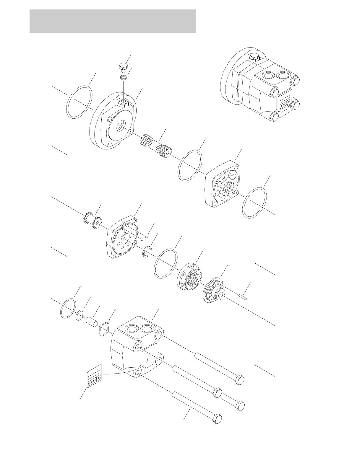
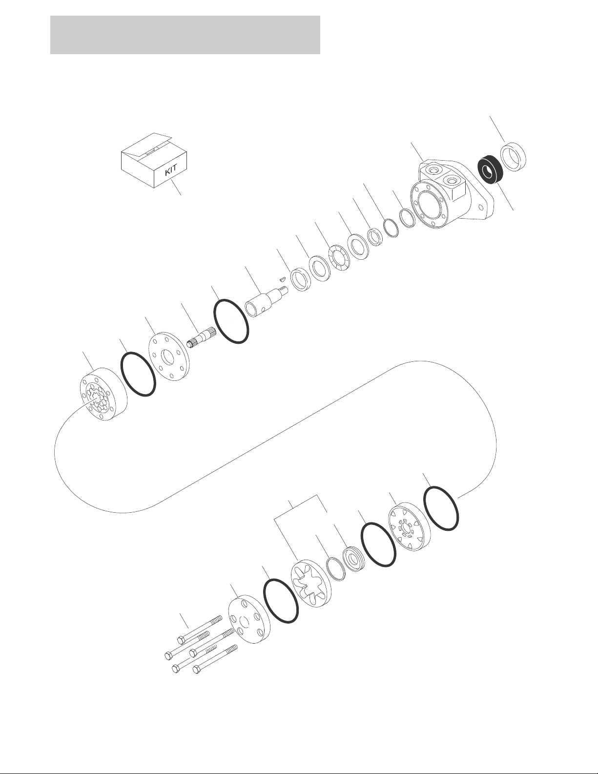
FIGURE 2-9.GEAR PUMP ASSEMBLY
2-30 340AJ 3121260
Page 53

SECTION 2 TURNTABLE
FIGURE 2-9. GEAR PUMP ASSEMBLY
ITEM # PART NUMBER QTY. DESCRIPTION REV.
1001117029 Ref GEAR PUMP ASSEMBLY A
Ref Note: For Items without P/Ns, replace complete pump.
Front Section Components
1 See Note Above 4 Bolt
2 See Note Above 1 Plate, End
3 See Note Above 2 Bearing
4 See Note Above 1 Housing
5 See Note Above 1 Drive Shaft Set
6 See Note Above 6 Pin, Dowel
7 See Note Above 1 Plate, Front
8 70002860 1 Seal Kit
8A Use 70002860 1 Seal, Lip (No Longer Available - was p/n 70002577)
9 70002862 1 Ring, Retaining
Rear Section Components
101 See Note Above 4 Bolt
102 See Note Above 1 Plate, End
103 See Note Above 2 Bearing
104 See Note Above 1 Housing
105 See Note Above 1 Drive Shaft Set
106 See Note Above 4 Pin, Dowel
107 See Note Above 1 Plate, Front
108 70002861 1 Seal Kit
109 See Note Above 1 Coupling
201 See Note Above 4 Bolt
3121260 340AJ 2-31
Page 54

SECTION 2 TURNTABLE
13
21
22
20
14
12
19
16
118105
106
107
102
102A
104
103
102
102
5
9
8
2
8
11111717101
8
9
3
204
205
203
205
202
15
9
1
5
309
308
301
304
303
306
305
307
302
300
201
OR
402
401
403
404
FIGURE 2-10.TANK INSTALLATIONS
2-32 340AJ 3121260
Page 55

SECTION 2 TURNTABLE
FIGURE 2-10. TANK INSTALLATIONS
ITEM # PART NUMBER QTY. DESCRIPTION REV.
Ref TANK INSTALLATIONS
1001115769 Ref Diesel Machines D
1001119102 Ref Gas Machines D
1 0100011 AR Compound, Locking
2 0701016 2 Bolt M10 x 40mm
3 0701022 1 Bolt M10 x 70mm
4Not Used
5 0761012 4 Bolt M10 x 25mm
6Not Used
7 0761214 2 Bolt M12 x 30mm
8 3291005 5 Locknut M10
9 4812002 5 Flatwasher M10
10 Not Used
11 4812102 2 Flatwasher M12
12 1001116339 1 Hydraulic Tank Assembly (See Items 101-107 for Breakdown)
13 1 Tank, Fuel Options (See Items 201-206 for Breakdown):
1001117897 Diesel Machines
1001117895 Gas Machines
14 1001118502 1 Shield, Bottom Tank
15 1001118509 1 Support, Tank
16 1001118510 1 Shield, Tank Neck
17 Not Used
18 1001119527 2 Screw, Button Head M10 x 16mm
19 1 Decal - Fuel Options:
1701505 Diesel
1701542 Gas
20 3820032 4 Rivet
21 1001128781 1 Seal, Neck
22 1001128782 1 Ring, Neck
1001116339 Ref HYDRAULIC TANK ASSEMBLY F
101 70002112 1 Plug, Magnetic
102 70002812 1 Hydraulic Breather/Filter Kit
102A 70002839 1 Gasket
103 See Note 1 Cover (Note: Not Available for Purchase)
104 See Note 6 Bolt (Note: Not Available for Purchase)
105 70002838 1 Cap, Fill
106 70002840 1 Decal - Filter Replacement
107 7024441 1 Gauge, Sight
3121260 340AJ 2-33
Page 56

SECTION 2 TURNTABLE
FIGURE 2-10. TANK INSTALLATIONS (CONTINUED)
ITEM # PART NUMBER QTY. DESCRIPTION REV.
Ref FUEL TANK ASSEMBLY
1001117897 Ref Diesel Machines E
1001117895 Ref Gas Machines (Not Shown) G
201 1 Cap, Fill Options:
1001128798 Diesel Machines (Non Locking) (Note: See 401-404 for
Lockable Cap)
1001128799 Gas Machines
202 1001118262 1 Sender
Use 1001118262 1 Seal, Sender (Note: Not Available for Purchase)
0721004 5 Screw #10-24NC x 1/2in
203 See Note 2 Tube, Steel with Elbow Fitting (Note: Not Available for Pur-
chase)
204See Note 1Plug (Note: Not Available for Purchase)
205 0100020 AR Sealant
206 1001129043 1 Valve, Vent (Gas Machines Only) (Not Shown - Located on Fill
Spout)
1001118975 Ref LP TANK INSTALLATION (GAS MACHINES ONLY)
300 4400275 1 Tank, LP
301 0760814 4 Bolt M8 x 30mm
302 1320220 1 LP Tank Clamp Kit
303 2180387 1 Fitting, LP
304 2180389 1 Fitting, Relief Valve
305 2180504 1 Fitting, Elbow
306 2220290 1 Fitting, Adapter
307 2720175 1 Hose
308 4811900 4 Flatwasher M8
309 1001118274 4 Nut, Retainer
310 1701543 1 Decal - LP
1001138829 Ref KIT, LOCKABLE FUEL CAP (DIESEL MACHINES ONLY)
(OPTIONAL)
401 0100093 AR Loctite
402 1001125283 1 Cap, Fill
403 1001138752 1 Adapter
404 1001139843 1 Gasket
A
2-34 340AJ 3121260
Page 57

SECTION 2 TURNTABLE
FIGURE 2-10. TANK INSTALLATIONS (CONTINUED)
ITEM # PART NUMBER QTY. DESCRIPTION REV.
3121260 340AJ 2-35
Page 58

SECTION 2 TURNTABLE
109
313
417
3
29
25
33
101
108
105
301
302
401
40214
112
110
110
32
13231
5
22
1
23
1
6
12
12
22
2
27
2
26 225
10
TO
GROUND
CONTROL
PAN EL
107
104
111
FIGURE 2-11.ELECTRICAL COMPONENTS INSTALLATION (TURNTABLE MOUNTED)
2-36 340AJ 3121260
Page 59

204
202
19
20
24
201
203
205
8
15
10
51322513227
14289
30
17
11
21
311
306
301
303
307
314
312
416
306
301
404
401
304
301OR407
401
403
409
405
415
410
411
408
418
SECTION 2 TURNTABLE
3121260 340AJ 2-37
Page 60

SECTION 2 TURNTABLE
FIGURE 2-11. ELECTRICAL COMPONENTS INSTALLATION (TURNTABLE MOUNTED)
ITEM # PART NUMBER QTY. DESCRIPTION REV.
1001119165 Ref ELECTRICAL INSTALLATION F
1 0100011 AR Compound, Locking
2 0100048 AR Sealant, Silicone
3 0140043 1 Alarm
4 0760505 1 Bolt M5 x 10mm
5 0760608 4 Bolt M6 x 16mm
6 0760621 5 Bolt M6 x 65mm
7 0760816 3 Bolt M8 x 40mm
8 0761012 1 Bolt M10 x 25mm
9 1321293 2 Clamp
10 1321716 3 P-Clamp
11 3290405 4 Locknut M4
12 3290601 10 Nut M6
13 3290605 2 Locknut M6
14 3290805 3 Locknut M8
15 3291005 1 Locknut M10
16 Not Used
17 4031512 4 Capscrew M4 x 40mm
18 4240033 2 Tie-Strap (Not Shown)
19 4460496 1 Lockwasher, Terminal
20 4460497 1 Nut, Terminal
21 4811400 4 Flatwasher M4
22 4811700 14 Flatwasher M6
23 1001120431 1 Module, Ground Control
24 1001106736 1 Cap, Dust
25 1001118218 1 Harness, Ground Interface (See Section 7 for Breakdown)
26 1001118293 1 Harness, Valve (See Section 7 for Breakdown)
27 1001118333 1 Harness, Mid Engine (See Section 7 for Breakdown)
28 1 Bracket, Switch Options:
1001119146 Prior to SN 0300158007
1001141710 SN 0300158007 to Present
29 1001119173 1 Ground Control Assembly (See Ground Control Assembly for
Breakdown)
30 1001119176 2 Limit Switch & Harness Assembly
1001119170 2 Switch, Limit (1 per Assembly)
31 2920129 8 Bulb, Light
32 1001119527 7 Screw, Button Head M10 x 16mm
33 1001125291 1 Shield, Ground Control
— — — — — — — — — —
2890230 1 Kit, Drive Orientation Mounting Plate (Includes Items 5, 7, 11, 13,
14, 17, 21, 22 & 28)
1001119277 Ref BATTERY INSTALLATION C
101 0400075 1 Battery
102 0760608 2 Bolt M6 x 16mm
103 3290605 2 Locknut M6
104 3291005 2 Locknut M10
2-38 340AJ 3121260
Page 61

SECTION 2 TURNTABLE
FIGURE 2-11. ELECTRICAL COMPONENTS INSTALLATION (TURNTABLE MOUNTED)
ITEM # PART NUMBER QTY. DESCRIPTION REV.
105 3820032 4 Rivet
106 4811702 4 Flatwasher M6
107 4812000 2 Flatwasher M10
108 0361810 1 Bar, Hold-down
109 1001117240 1 Cover
110 1001119278 2 Insulate
111 1001119280 2 Bolt M10 x 260mm
112 1320223 2 J-Clip
1001119268 Ref BEACON LIGHT INSTALLATION (AMBER) (OPTIONAL) D
Note: If machines is equipped with (BLUE) Strobe Light, see
Section 10 SkyGuard Kit.
201 0760410 2 Bolt M4 x 20mm
202 2920161 1 Strobe Light Assembly
7016319 1 Bulb, Replacement
7016372 1 Lens
203 3290405 2 Locknut M4
204 4060865 1 Guard
205 1001091102 2 Flatwasher M4
206 4240032 2 Tie-Strap (Not Shown)
1001120232 Ref TURNTABLE FLOODLIGHT INSTALLATION (OPTIONAL)
301 0100011 AR Compound, Locking
302 0760505 1 Bolt M5 x 10mm
303 0760610 4 Bolt M6 x 20mm
304 0762014 2 Bolt M20 x 30mm
305 1705170 1 Decal - Light (Not Shown - Located on Platform Console Box)
306 2920157 2 Floodlight
7024452 2 Bulb, Replacement (1 Per Assembly)
307 3290605 4 Locknut M6
308 4240032 2 Tie-Strap (Not Shown)
309 4240033 4 Tie-Strap (Not Shown)
310 4360522 1 Switch, Push Button (Not Shown - Located on Platform Console
Box)
311 1001120287 2 Mount, Light
312 1001120288 2 Mount, Light
313 1001120299 1 Harness, Turntable Floodlight (See Section 7 for Breakdown)
3740080 1 Relay
314 1320136 2 Clamp, Cable
1001149144 Ref HEAD & TAIL LIGHTS INSTALLATION (OPTIONAL) A
401 0100011 AR Compound, Locking
402 0760505 1 Bolt M5 x 10mm
403 0760610 4 Bolt M6 x 20mm
404 0762014 2 Bolt M20 x 30mm
405 1320136 2 Clamp, Cable
406 1705170 1 Decal - Light (Not Shown - Located on Platform Console Box)
3121260 340AJ 2-39
Page 62

SECTION 2 TURNTABLE
FIGURE 2-11. ELECTRICAL COMPONENTS INSTALLATION (TURNTABLE MOUNTED)
ITEM # PART NUMBER QTY. DESCRIPTION REV.
407 2920110 2 Light, Head
7016628 2 Bulb, Replacement (1 Per Assembly)
408 2920113 2 Light, Tail
409 3290605 4 Locknut M6
410 3311005 4 Locknut 10-24NC
411 3911036 4 Screw 10-24NC x 2-1/4in
412 4240032 2 Tie-Strap (Not Shown)
413 4240033 4 Tie-Strap (Not Shown)
414 4360522 1 Switch, Push Button (Not Shown - Located on Platform Console
Box)
415 4751000 4 Flatwasher #10 (Wide)
416 1001120288 2 Mount, Light
417 1001120299 1 Harness, Turntable Floodlight (See Section 7 for Breakdown)
3740080 1 Relay
418 1001149147 2 Mount, Light
2-40 340AJ 3121260
Page 63

SECTION 2 TURNTABLE
FIGURE 2-11. ELECTRICAL COMPONENTS INSTALLATION (TURNTABLE MOUNTED)
ITEM # PART NUMBER QTY. DESCRIPTION REV.
3121260 340AJ 2-41
Page 64

SECTION 2 TURNTABLE
9
103
103
10
5
3
8
8
2
477A
7B
11
12
101
101
101
101
102
103A
231
201
23266
6
1
FIGURE 2-12.GROUND CONTROL ASSEMBLY
2-42 340AJ 3121260
Page 65

SECTION 2 TURNTABLE
FIGURE 2-12. GROUND CONTROL ASSEMBLY
ITEM # PART NUMBER QTY. DESCRIPTION REV.
1001119173 Ref GROUND CONTROL ASSEMBLY C
1 1670829 1 Bezel
2 2420172 1 Gauge, Hourmeter
3 2760105 1 Housing, Display Light
4 3290505 2 Locknut M5
5 4060906 1 Shield, Toggle Switch
6 4360328 8 Switch, Toggle
7 4360475 1 Switch, Emergency Stop
7A 7020175 1 Cap, Mushroom Head
7B 7020176 1 Block, Contact
8 1001099125 2 Screw, Button Head M5 x 16mm
9 1001119172 1 Panel
10 1001119230 1 Decal - Ground Control
11 1001119232 1 Decal - Display Panel
12 4360476 1 Switch, Contact Block
Ref GROUND CONTROL ASSEMBLY
1001119399 Ref All Specs except CE Spec C
1001119400 Ref CE Spec Only C
101 3910804 6 Screw #8-32NC x 1/4in
102 1 Shim Options:
4070987 Prior to SN 0300175736
1001151393 SN 0300175736 to Present
103 1 Switch, Key Options:
4360469 All Specs except CE Spec
4360470 CE Spec Only
103A 2860030 1 Key
1001119165 Ref ADDITIONAL COMPONENTS
201 0100011 AR Compound, Locking
202 to 230 Not Used
231 2920129 8 Bulb, Light
232 1001119527 4 Screw, Button Head M10 x 16mm
3121260 340AJ 2-43
Page 66

SECTION 2 TURNTABLE
435
5
1
436
101
113
435437151
515
19292510153883893
9
1
34121
7
3
1
3
112611514111111
116
1
1
112
19
19
33
432
31
NOTE: REPLACEMENT DECALS MUST BE
ORDERED SEPARATELY - SECTION 8.
104
109
109
107
117
18
106
108
105
101
115
109
109
107
103
18
22
18
111
23
18
101
114
110
1
542
539
OR
544
546
545
538
541
540
531
53854154053
1
539
FIGURE 2-13.HOODS INSTALLATION
2-44 340AJ 3121260
Page 67

SECTION 2 TURNTABLE
NOTE: REPLACEMENT DECALS MUST BE
ORDERED SEPARATELY - SECTION 8.
201
214
24
211
205
208
202
204
9
12
21
20
7
12
4
11
30
201
212
11
2
8
2
8
31
25
31
2
5
19
3
28
15
15
15
15
10
2
6
27
22
18
18
18
18
17
1
1
11
19
19
5
209
209
206
203
210
201
213
207
4
11
16
2
7
2
7
3121260 340AJ 2-45
Page 68

SECTION 2 TURNTABLE
FIGURE 2-13. HOODS INSTALLATION
ITEM # PART NUMBER QTY. DESCRIPTION REV.
1001115768 Ref HOODS INSTALLATION D
1 80325 4 Hairpin
2 0100011 AR Compound, Locking
3 0760508 4 Bolt M5 x 16mm
4 0760608 AR Bolt M6 x 16mm
5 0760612 16 Bolt M6 x 25mm
6 0761009 2 Bolt M10 x 18mm
7 0761011 6 Bolt M5 x 16mm
8 0761210 2 Bolt M12 x 20mm
9 0761012 1 Bolt M10 x 25mm
10 3290505 4 Locknut M5
11 3290605 AR Locknut M6
12 3291005 6 Locknut M10
13 Not Used
14 3520030 1 Plug
15 4811600 8 Flatwasher M5
16 4811700 AR Flatwasher M6
17 4812000 6 Flatwasher M10
18 4812300 8 Flatwasher M16
19 5240600 22 Flatwasher M6 Hardened
20 1001117239 1 Box, Battery
21 1001117243 1 Cover, Turntable Center
22 1001117282 2 Rod, Loop
23 1001118360 1 Engine Side Hood Assembly (See Items 101-117 for Breakdown)
24 1001118361 1 Tank Side Hood Assembly (See Items 201-214 for Breakdown)
25 1001118459 1 Plate, Tank Side
26 1001119072 1 Plate, Engine Side
27 1001119080 1 Bracket, Hood Prop
28 1001119083 1 Mount, Latch
29 1001119084 1 Mount, Latch
30 1001119085 1 Tray, Hose
31 1001119092 4 Bumper
32 1001119103 1 Panel, Engine Side Top
33 1001119104 1 Panel
34 0701018 2 Bolt M10 x 50mm
1001118360 Ref ENGINE SIDE HOOD ASSEMBLY D
101 0100081 AR Adhesive
102 0760508 2 Bolt M5 x 16mm
103 0760608 5 Bolt M6 x 16mm
104 0760610 3 Bolt M6 x 20mm
105 2940109 1 Latch
106 8290505 2 Locknut M5
107 8290605 8 Locknut M6
108 4811600 4 Flatwasher M5
109 4811700 16 Flatwasher M6
110 1001117281 1 Hinge
2-46 340AJ 3121260
Page 69

SECTION 2 TURNTABLE
FIGURE 2-13. HOODS INSTALLATION (CONTINUED)
ITEM # PART NUMBER QTY. DESCRIPTION REV.
111 Use 1001118360 1 Hood, Replacement
112 1001119077 1 Pipe, Exhaust
113 1001119086 1 Seal
114 1001119087 1 Seal
115 1001119088 1 Seal
116 1001120748 1 Insulate, Heat Shield
117 1001120749 1 Insulate, Heat Shield
1001118361 Ref TANK SIDE HOOD ASSEMBLY B
201 0100081 AR Adhesive
202 0760508 2 Bolt M5 x 16mm
203 0760608 5 Bolt M6 x 16mm
204 2940109 1 Latch
205 8290505 2 Locknut M5
206 8290605 5 Locknut M6
207 3520030 1 Plug, Hole
208 4811600 4 Flatwasher M5
209 4811700 10 Flatwasher M6
210 1001117281 1 Hinge
211 Use 1001118361 1 Hood, Replacement
212 1001119089 1 Seal
213 1001119090 1 Seal
214 1001119091 1 Seal
1001115785 Ref HYDRAULIC COVER INSTALLATION E
301 to 387 Not Used
388 5250810 2 Bolt , Flange M8 x 20mm
389 8310686 2 Nut, Retainer M8
390 Not Used
391 1001121221 1 Cover, Tray
Ref KUBOTA ENGINE HOOD COMPONENTS (SN 0300153681 TO
PRESENT)
1001115767 Ref Machines without Arctic Package F
1001117978 Ref Machines with Arctic Package F
401 to 434 Not Used
435 2080040 10 Fastener, Huck
436 1001137451 1 Panel
437 1001137452 1 Mount, Panel
Ref GM ENGINE HOOD COMPONENTS
1001117975 Ref Machines without Arctic Package H
1001120248 Ref Machines with Arctic Package G
501 to 530 Not Used
531 3290605 AR Locknut M6
532 to 537 Not Used
3121260 340AJ 2-47
Page 70

SECTION 2 TURNTABLE
FIGURE 2-13. HOODS INSTALLATION (CONTINUED)
ITEM # PART NUMBER QTY. DESCRIPTION REV.
538 0760612 AR Bolt M6 x 25mm
539 2080040 7 Fastener, Huck
540 4740362 10 Flatwasher, Special
541 4811700 10 Flatwasher M6
542 1001137337 1 Vent
543 Not Used
544 1001137369 1 Plate
545 1001137397 1 Shield, Rubber
546 1001137401 1 Shield, Rubber
2-48 340AJ 3121260
Page 71

SECTION 2 TURNTABLE
FIGURE 2-13. HOODS INSTALLATION (CONTINUED)
ITEM # PART NUMBER QTY. DESCRIPTION REV.
3121260 340AJ 2-49
Page 72

SECTION 2 TURNTABLE
25A
22
28
30
24
12
23
25B
27
1
6
26
10
6
1
218151691425
3
11
7
17
1
29
17
1414181813551919
1
2
20
TANK SIDE REF.
DECAL PANEL REF.
FIGURE 2-14. GENERATOR INSTALLATION - GM ENGINE MACHINES (OPTIONAL)
2-50 340AJ 3121260
Page 73

SECTION 2 TURNTABLE
FIGURE 2-14. GENERATOR INSTALLATION - GM ENGINE MACHINES (OPTIONAL)
ITEM # PART NUMBER QTY. DESCRIPTION REV.
Ref GENERATOR INSTALLATION
1001121719 Ref 120V/60Hz Generator (ANSI, ANSI Export, CSA & Japanese
Specs)
1001121721 Ref 220V/60HZ Generator (ANSI Export & CSA Specs) D
1001121720 Ref 220V/50HZ Generator (ANSI Export Spec Only) D
1 0100011 AR Compound, Locking
2 0641506 1 Bolt 5/16in-18NC x 3/4in
3 0701012 1 Bolt M10 x 25mm
4 0701018 2 Bolt M10 x 50mm
5 0701219 2 Bolt M12 x 25mm
6 0760505 5 Bolt M5 x 10mm
7 0760612 2 Bolt M6 x 25mm
8 2820031 AR Heatshrink
9 3251102 1 Nameplate - Generator
10 3290505 2 Locknut M5
11 3290605 2 Locknut M6
12 3291005 1 Locknut M10
13 3291205 2 Locknut M12
14 4060802 1 Guard, Switch
15 4360336 1 Switch, Toggle
16 4740397 1 Washer
17 4811702 4 Flatwasher M6
18 4812000 2 Flatwasher M10
19 4812102 2 Flatwasher M12
20 4891500 1 Flatwasher 5/16in Hardened
21 4922641 1 Harness, On/Off Switch (See Section 7 for Breakdown)
22 1001119551 1 Mount, Generator
23 1001119553 1 Arm, Adjustment
24 1001119554 1 Support, Arm
25 1 Generator & Voltage Regulator Assembly Options:
1001119586 120V/60Hz C
1001119588 220V/60Hz C
1001119589 220V/50Hz C
25A Generator Only Options:
Ref Note: Replacement Generators come standard with p/n
3580134 pulley. This pulley may not be correct for all
applications. Refer to pulley options below
2460049 120V
1001100321 220V
1 Armature with Slip Rings Options:
70000122 120V Armature with Slip Rings
70000123 220V Armature with Slip Rings
7020109 4 Holder, Brush
7020108 4 Brush
7012513 4 Cap, Brush Holder
7012514 1 Fan
7020190 2 Bearing
D
3121260 340AJ 2-51
Page 74

SECTION 2 TURNTABLE
FIGURE 2-14. GENERATOR INSTALLATION - GM ENGINE MACHINES (OPTIONAL)
(CONTINUED)
ITEM # PART NUMBER QTY. DESCRIPTION REV.
25A Cont’d 7020110 1 End Bell, Front
7020111 1 End Bell, Rear
70003069 1 Cord, Power
1 Pulley Options:
70003068 60Hz
70003070 50Hz
7027887 1 Key, Woodruff
25B 1 Regulator, Voltage Options:
7026525 120V
70002238 220V
26 1 Control Box Assembly Options:
1001119633 120V B
1001119634 220V B
1 Circuit Breaker Options:
70002240 120V
70000126 220V
1 Voltmeter Options:
2420203 120V
7020192 220V
1 Receptacle Options:
7020152 1 Receptacle, Double (120V Box)
70003137 1 Receptacle, Single Twist Lock (120V Box)
70000124 1 Receptacle, Double (220V Box)
70000125 1 Receptacle, Single Twist Lock (220V Box)
2920162 1 Lamp
70002237 1 Diode
3520028 1 Plug, Hole
27 1001119773 1 Harness, Generator (See Section 7 for Breakdown)
28 1 V-Belt Options:
1001119881 60Hz
1001119882 50Hz
29 0760606 2 Bolt M6 x 12mm
30 1001125118 1 Shield, Pulley
2-52 340AJ 3121260
Page 75

SECTION 2 TURNTABLE
FIGURE 2-14. GENERATOR INSTALLATION - GM ENGINE MACHINES (OPTIONAL)
(CONTINUED)
ITEM # PART NUMBER QTY. DESCRIPTION REV.
3121260 340AJ 2-53
Page 76

SECTION 2 TURNTABLE
26
10
221919
131818
171720
23
25A
17
24
11
28
29
18
18
1
30
1
30
7
12
3
121
13131
32
1
144
5
5218
91516
14
1
6
1
6
27
25B
25
FIGURE 2-15. GENERATOR INSTALLATION - KUBOTA ENGINE MACHINES (OPTIONAL)
2-54 340AJ 3121260
Page 77

SECTION 2 TURNTABLE
FIGURE 2-15. GENERATOR INSTALLATION - KUBOTA ENGINE MACHINES (OPTIONAL)
ITEM # PART NUMBER QTY. DESCRIPTION REV.
Ref GENERATOR INSTALLATION
1001119582 Ref 120V/60Hz Generator (ANSI, ANSI Export, CSA & Japanese
Specs)
1001119583 Ref 120V/50Hz Generator (CE Specs) E
1001119584 Ref 220V/60HZ Generator (ANSI Export & CSA Specs) E
1001119585 Ref 220V/50HZ Generator (ANSI Export, Australian & CE Specs) E
1 0100011 AR Compound, Locking
2 0641506 1 Bolt 5/16in-18NC x 3/4in
3 0701012 1 Bolt M10 x 25mm
4 0701018 2 Bolt M10 x 50mm
5 0701219 2 Bolt M12 x 25mm
6 0760505 5 Bolt M5 x 10mm
7 0760612 2 Bolt M6 x 25mm
8 2820031 AR Heatshrink
9 3251102 1 Nameplate - Generator
10 3290505 2 Locknut M5
11 3290605 2 Locknut M6
12 3291005 1 Locknut M10
13 3291205 2 Locknut M12
14 4060802 1 Guard, Switch
15 4360336 1 Switch, Toggle
16 4740397 1 Washer
17 4811702 4 Flatwasher M6
18 4812000 5 Flatwasher M10
19 4812102 2 Flatwasher M12
20 4891500 1 Flatwasher 5/16in Hardened
21 4922641 1 Harness, On/Off Switch (See Section 7 for Breakdown)
22 1001119551 1 Mount, Generator
23 1001119553 1 Arm, Adjustment
24 1001119554 1 Support, Arm
25 1 Generator Assembly Options:
1001119586 120V/60Hz C
1001119587 120V/50Hz C
1001119588 220V/60Hz C
1001119589 220V/50Hz C
25A Generator Only Options:
Ref Note: Replacement Generators come standard with p/n
3580134 pulley. This pulley may not be correct for all
applications. Refer to pulley options below.
2460049 120V
1001100321 220V
1 Armature with Slip Rings Options:
70000122 120V Armature with Slip Rings
70000123 220V Armature with Slip Rings
7020109 4 Holder, Brush
7020108 4 Brush
7012513 4 Cap, Brush Holder
E
3121260 340AJ 2-55
Page 78

SECTION 2 TURNTABLE
FIGURE 2-15. GENERATOR INSTALLATION - KUBOTA ENGINE MACHINES (OPTIONAL)
(CONTINUED)
ITEM # PART NUMBER QTY. DESCRIPTION REV.
25A Cont’d 7012514 1 Fan
7020190 2 Bearing
7020110 1 End Bell, Front
7020111 1 End Bell, Rear
70003069 1 Cord, Power
1 Pulley Options:
70003068 60Hz
70003070 50Hz
7027887 1 Key, Woodruff
25B 1 Regulator, Voltage Options:
7026525 120V
70002238 220V
26 1 Control Box Assembly Options: B
1 Circuit Breaker Options:
70002240 120V
70000126 220V
1 Voltmeter Options:
2420203 120V
7020192 220V
1 Receptacle Options:
7020152 1 Receptacle, Double (120V Box)
70003137 1 Receptacle, Single Twist Lock (120V Box)
70000124 1 Receptacle, Double (220V Box)
70000125 1 Receptacle, Single Twist Lock (220V Box)
2920162 1 Lamp
70002237 1 Diode
3520028 1 Plug, Hole
27 1001119773 1 Harness, Generator (See Section 7 for Breakdown)
28 1 V-Belt Options:
1001119882 60Hz
1001119881 50Hz
29 1001118720 1 Pulley
30 1001119929 3 Bolt M10 x 35mm
31 0760606 2 Bolt M6 x 12mm
32 1001125118 1 Shield, Pulley
2-56 340AJ 3121260
Page 79

SECTION 3
BOOM
3121260 340AJ 3-1
Page 80

SECTION 3 BOOM
FIGURE 3-1. BOOM AND CYLINDERS INSTALLATION
3-2 340AJ 3121260
Page 81

SECTION 3 BOOM
FIGURE 3-1. BOOM AND CYLINDERS INSTALLATION
ITEM # PART NUMBER QTY. DESCRIPTION REV.
Ref BOOM & CYLINDERS INSTALLATIONS
1001115766 Ref Machines without Arctic Package C
1001119371 Ref Machines with Arctic Package C
1 0100011 AR Compound, Locking
2 0761011 1 Bolt M10 x 22mm
3 0761012 1 Bolt M10 x 25mm
4 0761014 2 Bolt M10 x 30mm
5 0761015 2 Bolt M10 x 35mm
6 0761212 2 Bolt M12 x 25mm
7 0761215 2 Bolt M12 x 35mm
8 3291005 3 Locknut M10
9 3291205 1 Locknut M12
10 3422576 2 Pin
11 3422582 1 Pin
12 3422709 1 Pin
13 3422790 1 Pin
14 3422792 1 Pin
15 3422814 1 Pin
16 3841143 4 Keeper, Pin
17 3841203 4 Keeper, Pin
18 4812000 4 Flatwasher M10
19 5251010 3 Bolt, Flanged M10 x 20mm
20 1001120976 1 Master Cylinder Assembly (See Section 5 for Breakdown)
21 1001125235 1 Rest, Boom
22 1001109528 1 Pin
23 1001112607 2 Pad, Boom Rest
24 1001115672 1 Tower Boom Assembly (See Tower Boom Assembly for Break-
down)
25 1001117375 1 Level Cylinder Assembly - Platform (Slave) (See Section 5 for
Breakdown)
26 1001117640 1 Lift Cylinder Assembly - Main Boom (See Section 5 for
Breakdown)
27 1 Jib Assembly (See Jib Assembly & Platform Support Installation
for Breakdown)
1001117884 Machines without Arctic Package
1001119370 Machines with Arctic Package
28 1001117885 1 Main Boom Assembly Options (See Main Boom Assembly for
Breakdown):
3121260 340AJ 3-3
Page 82

SECTION 3 BOOM
34
135
138
150
137
32
32
32
323131
21
22
253131
101031
31
30
27
27
31
31
31
31
23
24
133
144
20
8
119
119
4
1
5
511
16
16
112
149
103
120
120
111
110
135
118
30
3
3
15
15
12
12
149
146
101
29272727171616
1655511171
28
28
16
16
6
1
1
6
113
126
105
5
1
5
1
16
16
131313318214
181812
111126
9
9
19
111
124
117
FIGURE 3-2. TOWER BOOM ASSEMBLY
3-4 340AJ 3121260
Page 83

SECTION 3 BOOM
FIGURE 3-2. TOWER BOOM ASSEMBLY
ITEM # PART NUMBER QTY. DESCRIPTION REV.
1001115672 Ref TOWER BOOM ASSEMBLY C
1 0100011 AR Compound, Locking
2 0701027 1 Bolt M10 x 100mm
3 0761015 2 Bolt M10 x 35mm
4 0761210 2 Bolt M12 x 20mm
5 0761212 7 Bolt M12 x 25mm
6 0761214 2 Bolt M12 x 30mm
7 0761615 2 Bolt M16 x 35mm
8 0940048 1 Bumper
9 0961948 2 Bearing
10 0962224 2 Bearing
11 0962259 2 Bearing
12 3291005 3 Locknut M10
13 3422787 2 Pin
14 3422788 1 Pin
15 3841143 2 Keeper, Pin
16 3841203 9 Keeper, Pin
17 3841258 1 Keeper, Pin
18 4812000 6 Flatwasher M10
19 1001115649 1 Upright (Bottom)
20 1001115650 1 Upright (Top)
21 1001115657 1 Link, Lower Boom (Bottom)
22 1001115661 1 Link, Lower Boom (Top)
23 1001115663 1 Link, Mid Boom (Bottom)
24 1001115669 1 Link, Mid Boom (Top)
25 1001122527 1 Lift Cylinder Assembly - Tower Boom (See Section 5 for
Breakdown)
26 1001115870 1 Link, Timing
27 1001116546 5 Pin
28 1001116547 2 Pin
29 1001116548 1 Pin
30 1001116549 2 Pin
31 1001118665 10 Bearing
32 1001118666 4 Bearing
33 0761010 4 Bolt M10 x 20mm
34 3340758 2 Pad, Wear
Ref LIMIT SWITCHES, CABLES & CLAMPS INSTALLATION
1001115784 Ref Machines without Arctic Package F
1001119937 Ref Machines with Arctic Package F
101 0100011 AR Compound, Locking
102 Not Used
103 0760621 4 Bolt M6 x 65mm
104 Not Used
105 0700829 4 Bolt M8 x 120mm
106 to 109 Not Used
110 1670899 2 Cover, Switch
3121260 340AJ 3-5
Page 84

SECTION 3 BOOM
FIGURE 3-2. TOWER BOOM ASSEMBLY (CONTINUED)
ITEM # PART NUMBER QTY. DESCRIPTION REV.
111 3290405 6 Locknut M4
112 3290605 5 Locknut M6
113 3290805 6 Locknut M8
114 to 116 Not Used
117 4031510 2 Capscrew M4 x 30mm
118 4031512 4 Capscrew M4 x 40mm
119 4060808 1.8ft/
55cm
120 4240018 AR Tie-Strap
121 to 123 Not Used
124 4811400 2 Flatwasher M4
125 Not Used
126 4811900 8 Flatwasher M8
127 to 132 Not Used
133 1001116433 2 Guard, Hose
134 Not Used
135 1001118292 1 Harness, Tower Boom (See Section 7 for Breakdown)
4360548 3 Switch, Limit
136 Not Used
137 1001118592 2 Plate, Hose Clamp
138 1001118593 2 Plate, Hose Clamp
139 to 143 Not Used
144 1001119197 4 Clamp, Hose
145 Not Used
146 0760605 2 Bolt M6 x 10mm
147 to 148 Not Used
149 4811702 10 Flatwasher M6
150 3340901 4 Pad, Rubber
151 1001140524 1 Harness, Upper Boom (See Section 7 for Breakdown)
Flex-Trim
(SN 0300161809 to Present)
3-6 340AJ 3121260
Page 85

SECTION 3 BOOM
FIGURE 3-2. TOWER BOOM ASSEMBLY (CONTINUED)
ITEM # PART NUMBER QTY. DESCRIPTION REV.
3121260 340AJ 3-7
Page 86

SECTION 3 BOOM
13
13
6
6
5
16
4
4
12
1
11
1
11
1
11
1
18
18
19
19
7
8
8
7
8
7
213
202
215
202
215
231
245
226
226
204
1
3
9
14
1
2
10
15
4
4
17
232
228
229
245
243
234
101
102
103
107
1
04105
101
101
108
103
106
20221520221521322
6226
204
2
45231
18181
111
11111111787878191
9
FIGURE 3-3. MAIN BOOM ASSEMBLY
3-8 340AJ 3121260
Page 87

SECTION 3 BOOM
FIGURE 3-3. MAIN BOOM ASSEMBLY
ITEM # PART NUMBER QTY. DESCRIPTION REV.
1001117885 Ref MAIN BOOM ASSEMBLY C
1 0100011 AR Compound, Locking
2 0711227 4 Bolt M12 x 100mm (Grade 10.9)
3 0760812 4 Bolt M8 x 25mm
4 0961948 4 Bushing
5 3422745 1 Pin
6 3760115 2 Ring, Retaining
7 4070897 16 Shim 18Ga
8 4070898 12 Shim 11Ga
9 4811902 4 Flatwasher M8
10 5241200 4 Flatwasher M12 Hardened
11 5251010 28 Bolt, Flanged M10 x 20mm
12 5251012 4 Bolt, Flanged M10 x 25mm
13 1001120974 1 Telescope Cylinder Assembly (See Section 5 for Breakdown):
14 1001108290 1 Cover, Boom End
15 1001116876 1 Boom, Base
16 1001116877 1 Boom, Fly
17 1001118274 4 Nut, Retainer M8
18 1001118287 8 Pad, Wear
19 1001118288 8 Pad, Wear
1001119504 Ref POWER TRACK ASSEMBLY B
101 0100011 AR Compound, Locking
102 0761007 4 Bolt M10 x 14mm
103 4812000 8 Flatwasher M10
104 5221000 4 Nut, Flange M10 (Class 10)
105 8310668 4 Screw, Button Head M10 x 25mm (Grade 10.9)
106 1001099834 1 Carrier, Power Track
70001996 1 Repair Kit (Includes One 2FT Section of Carrier)
70001998 1 Bracket Kit (Includes 4 Mounting Feet & Hardware to Attach to
Carrier)
107 1001119513 1 Tube, Support
108 1001119527 4 Screw, Button Head M10 x 16mm
Ref LIMIT SWITCHES, CABLES & CLAMPS INSTALLATION
1001115784 Ref Machines without Arctic Package F
1001119937 Ref Machines with Arctic Package F
201 Not Used
202 0100081 AR Adhesive
203 Not Used
204 0700820 2 Bolt M8 x 60mm
205 to 212 Not Used
213 3290805 6 Locknut M8
214 Not Used
215 3340939 4 Pad, Rubber
216 to 225 Not Used
3121260 340AJ 3-9
Page 88

SECTION 3 BOOM
FIGURE 3-3. MAIN BOOM ASSEMBLY (CONTINUED)
ITEM # PART NUMBER QTY. DESCRIPTION REV.
226 4811900 8 Flatwasher M8
227 Not Used
228 5260800 6 Nut, Flange M8 (Class 10)
229 5281920 6 Capscrew, Cup Point M8 x 80mm
230 Not Used
231 1001106757 2 Plate, Clamp
232 1001107152 1 Plate, Shield
233 Not Used
234 1001118274 6 Nut, Retainer
235 to 242 Not Used
243 2 Plate, Hose Clamp Options:
1001119194 Machines without Arctic Package
1001119195 Machines with Arctic Package
244 Not Used
245 1001119228 8 Pushnut M8
3-10 340AJ 3121260
Page 89

SECTION 3 BOOM
FIGURE 3-3. MAIN BOOM ASSEMBLY (CONTINUED)
ITEM # PART NUMBER QTY. DESCRIPTION REV.
3121260 340AJ 3-11
Page 90

SECTION 3 BOOM
106
17
16
6
5
15
2
14
9
5
4
4
3
3
3
3
8
8
8
8
8
8
13
13
10
10
6
107
101
102
7
7
7
12
12
12
12
11
1031051051041
FIGURE 3-4. JIB ASSEMBLY & PLATFORM SUPPORT INSTALLATION
3-12 340AJ 3121260
Page 91

SECTION 3 BOOM
FIGURE 3-4. JIB ASSEMBLY & PLATFORM SUPPORT INSTALLATION
ITEM # PART NUMBER QTY. DESCRIPTION REV.
Ref JIB ASSEMBLY
1001117884 Ref Machines without Arctic Package B
1001119370 Ref Machines with Arctic Package B
1 1 Platform Rotator Assembly Options (See Platform Rotator
Assembly for Breakdown)
0060044 Machines without Arctic Package
1001119369 Machines with Arctic Package
2 0700818 2 Bolt M8 x 50mm
3 0701018 4 Bolt M10 x 50mm
4 0701020 2 Bolt M10 x 60mm
5 0961951 2 Bushing
6 0962292 2 Bushing
7 3290805 4 Locknut M8
8 3291005 6 Locknut M10
9 3340860 4 Pad, Rubber
10 3422791 2 Pin
11 3572551 2 Channel, Hose Carrier
12 4811902 6 Flatwasher M8
13 1001116550 2 Pin
14 1001123004 1 Lift Cylinder Assembly - Jib (See Section 5 for Breakdown)
15 1001118394 1 Pivot, Jib
16 1001118482 1 Link, Jib (Top)
17 1001118516 2 Link, Jib (Bottom)
Ref PLATFORM SUPPORT INSTALLATION A
1001115834 Ref Machines without Load Sensing
See Note Ref Machines with Load Sensing (Note: For replacement parts,
contact JLG Customer Service & request manual p/n
3124287.)
101 0100011 AR Compound, Locking
102 0681608 6 Bolt 3/8in-16NC x 1in (Grade 8)
103 0761015 8 Bolt M10 x 35mm
104 3291005 1 Locknut M10
105 4812000 1 Flatwasher M10
106 1 Support, Platform Options:
4846608 Machines without Load Sensing
See Note Above Machines with Load Sensing
107 4891600 8 Flatwasher 3/8in Hardened
3121260 340AJ 3-13
Page 92

SECTION 3 BOOM
54
54
1
25
32
32
34
342527
24
4
42
423202241
5
26
26
51
52
2
1B
1A
7
7
53
53
53
53
FIGURE 3-5. PLATFORM ROTATOR ASSEMBLY
3-14 340AJ 3121260
Page 93

SECTION 3 BOOM
FIGURE 3-5. PLATFORM ROTATOR ASSEMBLY
ITEM # PART NUMBER QTY. DESCRIPTION REV.
Ref PLATFORM ROTATOR ASSEMBLY
0060044 Ref Machines without Arctic Package D
1001119369 Ref Machines with Arctic Package
1 See Note 1 Case/Bracket Weldment
(Note: Not Available - Purchase Complete Rotator)
1A 0962257 2 Bushing, Garmax
1B 0961947 2 Bushing, Garmax
2 1 Shaft Options:
7017120 Helac Control #25928
7017196 Helac Control #26962
See Note Helac Control #33226
(Note: Not Available - Purchase Complete Rotator)
3 1 Sleeve, Piston Options:
7017121 Helac Control #25928
7027900 Helac Control #26962
See Note Helac Control #33226
(Note: Not Available - Purchase Complete Rotator)
41Cap, End
See Note Helac Control #25928
(Note: Not Available - Purchase Complete Rotator)
7027901 Helac Control #26962
See Note Helac Control #33226
(Note: Not Available - Purchase Complete Rotator)
5 See Note 3 Capscrew 1/4in-20NC (Grade 8)
(Note: Not Available - Purchase Locally)
6Not Used
7 7017126 1 Tie Rod Assembly
8 to 19 Not Used
20 See Note 1 Seal, Rod (Note: Use Item 52)
21 Not Used
22 See Note 1 Seal, Piston (Note: Use Item 52)
23 Not Used
24 See Note 1 Seal, Cap (Note: Use Item 52)
25 See Note 2 Packing, Bearing (Note: Use Item 52)
26 See Note 2 Seal (Note: Use Item 52)
27 See Note 1 Ring, Cap Back-Up (Note: Use Item 52)
28 to 31 Not Used
32 Use 7017122 2 Bearing, Shaft
33 Not Used
34 Use 7017122 2 Washer, Thrust
35 to 40 Not Used
41 7017172 1 Counterbalance Valve Assembly
7017192 2 Cartridge, Valve (No Seal Kit Available)
42 See Note 2 Bushing, Shaft (Note: Not Available for Purchase)
43 to 50 Not Used
51 7017122 1 Bearing Kit (Includes Items 32 & 34):
52 1 Seal Kit Options (Includes Items 20,22,24,25,26 & 27):
7017127 Standard
70000341 Cold Climate
3121260 340AJ 3-15
Page 94

SECTION 3 BOOM
FIGURE 3-5. PLATFORM ROTATOR ASSEMBLY (CONTINUED)
ITEM # PART NUMBER QTY. DESCRIPTION REV.
53 7017123 1 Hardware Kit
54 70001697 4 Screw, Countersunk 1/4in-20NC x 3/8in (Grade 8)
3-16 340AJ 3121260
Page 95

SECTION 3 BOOM
FIGURE 3-5. PLATFORM ROTATOR ASSEMBLY (CONTINUED)
ITEM # PART NUMBER QTY. DESCRIPTION REV.
3121260 340AJ 3-17
Page 96

SECTION 3 BOOM
10
18511717
12
9
14
5
1
51514
6
6
1
1
FIGURE 3-6. BOOM VALVES INSTALLATION
3-18 340AJ 3121260
Page 97

SECTION 3 BOOM
FIGURE 3-6. BOOM VALVES INSTALLATION
ITEM # PART NUMBER QTY. DESCRIPTION REV.
1001115780 Ref BOOM VALVES INSTALLATION G
1 0100011 AR Compound, Locking
2 to3 Not Used
4 4812002 2 Flatwasher M10
5 5250810 10 Bolt, Flanged M8 x 20mm
6 5250812 3 Bolt, Flanged M8 x 25mm
7 to 8 Not Used
9 1001116228 1 Valve Assembly - Fly Boom (See Boom Valve Assemblies for
Breakdown)
10 1 Valve Assembly - Boom Upright (See Boom Valve Assemblies for
Breakdown)
Use 1001136244 Prior to SN 0300158122 (was p/n 1001116229)
1001136244 SN 0300158122 to Present
11 Not Used
12 1001116835 1 Shield
13 Not Used
14 1001118274 1 Nut, Retainer
15 to 16 Not Used
17 5250808 2 Bolt, Flanged M8 x 16mm
18 1001118595 1 Plate, Cover
3121260 340AJ 3-19
Page 98

SECTION 3 BOOM
FIGURE 3-7. BOOM VALVE ASSEMBLIES
3-20 340AJ 3121260
Page 99

SECTION 3 BOOM
FIGURE 3-7. BOOM VALVE ASSEMBLIES
ITEM # PART NUMBER QTY. DESCRIPTION REV.
1001116228 Ref FLY BOOM VALVE ASSEMBLY D
1 7012955 1 Cartridge, Check Valve
7012967 1 Seal Kit - 7012955 Cartridge
2 7023970 1 Cartridge, Flow Regulator
7012953 1 Seal Kit - 7023970 Cartridge
3 7017452 1 Cartridge, Solenoid Valve (without Coil) (Rotate)
7017402 1 Seal Kit - 7017452 Cartridge
4 7012941 1 Cartridge, Solenoid Valve (without Coil) (Jib)
7010543 1 Seal Kit - 7012941 Cartridge
5 3 Coil Options:
7024885 Prior to SN 0300158122
70002386 SN 0300158122 to Present
Ref BOOM UPRIGHT VALVE ASSEMBLIES
1001116229 Ref Prior to SN 0300158122 (Original Equipment) E
1001136244 Ref SN 0300158122 to Present (Service Replacement) A
Ref Note: Original Equipment Valve may have been replaced
with Service Replacement Valve. Identify p/n stamped on
valve before ordering parts.
101 7012955 2 Cartridge, Check Valve
7012967 2 Seal Kit - 7012955 Cartridge
102 7017452 2 Cartridge, Solenoid Valve (without Coil) (Telescope / Platform
Level)
7017402 2 Seal Kit - 7017452 Cartridge
103 7017427 1 Cartridge, Relief
7012998 1 Seal Kit - 7017427 Cartridge
104 70002954 1 Cartridge, Relief
7012998 1 Seal Kit - 70002954 Cartridge
105 4 Coil Options:
70001977 Used on Valve p/n 1001116229
70002386 Used on Valve p/n 1001136244
106 See Note 2 Orifice (Note: Not Available for Purchase)
107 7017498 1 Piston, Pilot
3121260 340AJ 3-21
Page 100

SECTION 3 BOOM
FIGURE 3-7. BOOM VALVE ASSEMBLIES (CONTINUED)
ITEM # PART NUMBER QTY. DESCRIPTION REV.
3-22 340AJ 3121260
 Loading...