

Page 1

Service and Maintenance Manual
Models
1932RS/6RS
3248RS/10RS
3121273
November 26, 2018 - Rev F
Page 2

Page 3

INTRODUCTION
SECTION A. INTRODUCTION - MAINTENANCE SAFETY PRECAUTIONS
GENERAL
This section contains the general safety precautions
which must be observed during maintenance of the
aerial platform. It is of utmost importance that maintenance personnel pay strict attention to these warnings
and precautions to avoid possible injury to themselves
or others, or damage to the equipment. A maintenance
program must be followed to ensure that the machine is
safe to operate.
MODIFICATION OR ALTERATION OF AN AERIAL WORK PLATFORM
SHALL BE MADE ONLY WITH WRITTEN PERMISSION FROM THE MANUFACTURER.
The specific precautions to be observed during maintenance are inserted at the appropriate point in the manual. These precautions are, for the most part, those that
apply when servicing hydraulic and larger machine
component parts.
Your safety, and that of others, is the first consideration
when engaging in the maintenance of equipment.
Always be conscious of weight. Never attempt to move
heavy parts without the aid of a mechanical device. Do
not allow heavy objects to rest in an unstable position.
When raising a portion of the equipment, ensure that
adequate support is provided.
SINCE THE MACHINE MANUFACTURER HAS NO DIRECT CONTROL OVER
THE FIELD INSPECTION AND MAINTENANCE, SAFETY IN THIS AREA
RESPONSIBILITY OF THE OWNER/OPERATOR.
HYDRAULIC SYSTEM SAFETY
It should be noted that the machines hydraulic systems
operate at extremely high potentially dangerous pressures. Every effort should be made to relieve any system
pressure prior to disconnecting or removing any portion of the system.
MAINTENANCE
FAILURE TO COMPLY WITH SAFETY PRECAUTIONS LISTED IN THIS SECTION COULD RESULT IN MACHINE DAMAGE, PERSONNEL INJURY OR
DEATH AND IS A SAFETY VIOLATION.
• ENSURE REPLACEMENT PARTS OR COMPONENTS ARE
IDENTICAL OR EQUIVALENT TO ORIGINAL PARTS OR
COMPONENTS.
• NO SMOKING IS MANDATORY. NEVER REFUEL DURING
ELECTRICAL STORMS. ENSURE THAT FUEL CAP IS
CLOSED AND SECURE AT ALL OTHER TIMES.
• REMOVE ALL RINGS, WATCHES AND JEWELRY WHEN
PERFORMING ANY MAINTENANCE.
• DO NOT WEAR LONG HAIR UNRESTRAINED, OR
LOOSE-FITTING CLOTHING AND NECKTIES WHICH ARE
APT TO BECOME CAUGHT ON OR ENTANGLED IN
EQUIPMENT.
• OBSERVE AND OBEY ALL WARNINGS AND CAUTIONS
ON MACHINE AND IN SERVICE MANUAL.
• KEEP OIL, GREASE, WATER, ETC. WIPED FROM STANDING SURFACES AND HAND HOLDS.
• USE CAUTION WHEN CHECKING A HOT, PRESSURIZED
COOLANT SYSTEM.
• NEVER WORK UNDER AN ELEVATED SCISSOR UNTIL
PLATFORM HAS BEEN SAFELY RESTRAINED FROM ANY
MOVEMENT BY BLOCKING OR OVERHEAD SLING, OR
SAFETY PROP HAS BEEN ENGAGED.
• BEFORE MAKING ADJUSTMENTS, LUBRICATING OR
PERFORMING ANY OTHER MAINTENANCE, SHUT OFF
ALL POWER CONTROLS.
• BATTERY SHOULD ALWAYS BE DISCONNECTED DURING REPLACEMENT OF ELECTRICAL COMPONENTS.
• KEEP ALL SUPPORT EQUIPMENT AND ATTACHMENTS
STOWED IN THEIR PROPER PLACE.
• USE ONLY APPROVED, NONFLAMMABLE CLEANING
SOLVENTS.
3121273 A-1
Page 4

INTRODUCTION
Original Issue A - January 30, 2012
Revised B - August 1, 2012
Revised C - January 29, 2013
Revised D - April 8, 2013
Revised E - June 29, 2018 - Revised Covers
Revised F - November 26, 2018
REVISION LOG
A-2 3121273
Page 5

TABLE OF CONTENTS
TABLE OF CONTENTS
SECTION A - INTRODUCTION - MAINTENANCE SAFETY PRECAUTIONS
A General . . . . . . . . . . . . . . . . . . . . . . . . . . . . . . . . . . . . . . . . . . . . . . . . . . . . . . . . . . . . . . . . . . . . . . . . . . . . . . . . . . . . . . . . . . . . A
Hydraulic System Safety . . . . . . . . . . . . . . . . . . . . . . . . . . . . . . . . . . . . . . . . . . . . . . . . . . . . . . . . . . . . . . . . . . . . . . . . . . . . A
Maintenance. . . . . . . . . . . . . . . . . . . . . . . . . . . . . . . . . . . . . . . . . . . . . . . . . . . . . . . . . . . . . . . . . . . . . . . . . . . . . . . . . . . . . . . A
SECTION 1 - SPECIFICATIONS
1.1 Specifications . . . . . . . . . . . . . . . . . . . . . . . . . . . . . . . . . . . . . . . . . . . . . . . . . . . . . . . . . . . . . . . . . . . . . . . . . . . . . . . . . . . . . . 1-1
Platform Capacities . . . . . . . . . . . . . . . . . . . . . . . . . . . . . . . . . . . . . . . . . . . . . . . . . . . . . . . . . . . . . . . . . . . . . . . . . . . 1-1
Dimensional Data . . . . . . . . . . . . . . . . . . . . . . . . . . . . . . . . . . . . . . . . . . . . . . . . . . . . . . . . . . . . . . . . . . . . . . . . . . . . . 1-2
Tires . . . . . . . . . . . . . . . . . . . . . . . . . . . . . . . . . . . . . . . . . . . . . . . . . . . . . . . . . . . . . . . . . . . . . . . . . . . . . . . . . . . . . . . . . . 1-2
Batteries . . . . . . . . . . . . . . . . . . . . . . . . . . . . . . . . . . . . . . . . . . . . . . . . . . . . . . . . . . . . . . . . . . . . . . . . . . . . . . . . . . . . . . 1-2
Battery Quick-Disconnect - (If Equipped) . . . . . . . . . . . . . . . . . . . . . . . . . . . . . . . . . . . . . . . . . . . . . . . . . . . . . . . 1-2
Electrical System . . . . . . . . . . . . . . . . . . . . . . . . . . . . . . . . . . . . . . . . . . . . . . . . . . . . . . . . . . . . . . . . . . . . . . . . . . . . . . 1-3
Motors. . . . . . . . . . . . . . . . . . . . . . . . . . . . . . . . . . . . . . . . . . . . . . . . . . . . . . . . . . . . . . . . . . . . . . . . . . . . . . . . . . . . . . . . 1-3
Travel Speed . . . . . . . . . . . . . . . . . . . . . . . . . . . . . . . . . . . . . . . . . . . . . . . . . . . . . . . . . . . . . . . . . . . . . . . . . . . . . . . . . . 1-3
Lift Speed. . . . . . . . . . . . . . . . . . . . . . . . . . . . . . . . . . . . . . . . . . . . . . . . . . . . . . . . . . . . . . . . . . . . . . . . . . . . . . . . . . . . . 1-3
1.2 Critical Stability Weights. . . . . . . . . . . . . . . . . . . . . . . . . . . . . . . . . . . . . . . . . . . . . . . . . . . . . . . . . . . . . . . . . . . . . . . . . . . . 1-4
1.3 Lubrication . . . . . . . . . . . . . . . . . . . . . . . . . . . . . . . . . . . . . . . . . . . . . . . . . . . . . . . . . . . . . . . . . . . . . . . . . . . . . . . . . . . . . . . . 1-4
Hydraulic Oil . . . . . . . . . . . . . . . . . . . . . . . . . . . . . . . . . . . . . . . . . . . . . . . . . . . . . . . . . . . . . . . . . . . . . . . . . . . . . . . . . . 1-4
Pressure Settings . . . . . . . . . . . . . . . . . . . . . . . . . . . . . . . . . . . . . . . . . . . . . . . . . . . . . . . . . . . . . . . . . . . . . . . . . . . . . 1-4
1.4 Limit Switches . . . . . . . . . . . . . . . . . . . . . . . . . . . . . . . . . . . . . . . . . . . . . . . . . . . . . . . . . . . . . . . . . . . . . . . . . . . . . . . . . . . . . 1-5
Tilt Alarm . . . . . . . . . . . . . . . . . . . . . . . . . . . . . . . . . . . . . . . . . . . . . . . . . . . . . . . . . . . . . . . . . . . . . . . . . . . . . . . . . . . . . 1-5
High Drive Speed Cutout . . . . . . . . . . . . . . . . . . . . . . . . . . . . . . . . . . . . . . . . . . . . . . . . . . . . . . . . . . . . . . . . . . . . . . 1-5
1.5 Cylinder Specifications . . . . . . . . . . . . . . . . . . . . . . . . . . . . . . . . . . . . . . . . . . . . . . . . . . . . . . . . . . . . . . . . . . . . . . . . . . . . . 1-5
1.6 Major Component Weights . . . . . . . . . . . . . . . . . . . . . . . . . . . . . . . . . . . . . . . . . . . . . . . . . . . . . . . . . . . . . . . . . . . . . . . . 1-5
1.7 Torque Requirements . . . . . . . . . . . . . . . . . . . . . . . . . . . . . . . . . . . . . . . . . . . . . . . . . . . . . . . . . . . . . . . . . . . . . . . . . . . . . . 1-5
Torque Charts. . . . . . . . . . . . . . . . . . . . . . . . . . . . . . . . . . . . . . . . . . . . . . . . . . . . . . . . . . . . . . . . . . . . . . . . . . . . . . . . . 1-6
SECTION 2 - GENERAL
2.1 Machine Preparation, Inspection, and Maintenance . . . . . . . . . . . . . . . . . . . . . . . . . . . . . . . . . . . . . . . . . . . . . . . . . 2-1
General . . . . . . . . . . . . . . . . . . . . . . . . . . . . . . . . . . . . . . . . . . . . . . . . . . . . . . . . . . . . . . . . . . . . . . . . . . . . . . . . . . . . . . . 2-1
Preparation, Inspection, and Maintenance . . . . . . . . . . . . . . . . . . . . . . . . . . . . . . . . . . . . . . . . . . . . . . . . . . . . . 2-1
Pre-Start Inspection . . . . . . . . . . . . . . . . . . . . . . . . . . . . . . . . . . . . . . . . . . . . . . . . . . . . . . . . . . . . . . . . . . . . . . . . . . . 2-1
Pre-Delivery Inspection and Frequent Inspection. . . . . . . . . . . . . . . . . . . . . . . . . . . . . . . . . . . . . . . . . . . . . . . 2-1
Annual Machine Inspection. . . . . . . . . . . . . . . . . . . . . . . . . . . . . . . . . . . . . . . . . . . . . . . . . . . . . . . . . . . . . . . . . . . . 2-1
Preventative Maintenance. . . . . . . . . . . . . . . . . . . . . . . . . . . . . . . . . . . . . . . . . . . . . . . . . . . . . . . . . . . . . . . . . . . . . 2-1
2.2 Preventive Maintenance and Inspection Schedule. . . . . . . . . . . . . . . . . . . . . . . . . . . . . . . . . . . . . . . . . . . . . . . . . . . 2-2
Maintenance and Inspection Schedule Codes:. . . . . . . . . . . . . . . . . . . . . . . . . . . . . . . . . . . . . . . . . . . . . . . . . . 2-2
Footnotes: . . . . . . . . . . . . . . . . . . . . . . . . . . . . . . . . . . . . . . . . . . . . . . . . . . . . . . . . . . . . . . . . . . . . . . . . . . . . . . . . . . . . 2-2
2.3 Service and Guidelines . . . . . . . . . . . . . . . . . . . . . . . . . . . . . . . . . . . . . . . . . . . . . . . . . . . . . . . . . . . . . . . . . . . . . . . . . . . . . 2-5
General . . . . . . . . . . . . . . . . . . . . . . . . . . . . . . . . . . . . . . . . . . . . . . . . . . . . . . . . . . . . . . . . . . . . . . . . . . . . . . . . . . . . . . . 2-5
Safety and Workmanship . . . . . . . . . . . . . . . . . . . . . . . . . . . . . . . . . . . . . . . . . . . . . . . . . . . . . . . . . . . . . . . . . . . . . . 2-5
Cleanliness. . . . . . . . . . . . . . . . . . . . . . . . . . . . . . . . . . . . . . . . . . . . . . . . . . . . . . . . . . . . . . . . . . . . . . . . . . . . . . . . . . . . 2-5
Components Removal and Installation. . . . . . . . . . . . . . . . . . . . . . . . . . . . . . . . . . . . . . . . . . . . . . . . . . . . . . . . . 2-5
Component Disassembly and Reassembly . . . . . . . . . . . . . . . . . . . . . . . . . . . . . . . . . . . . . . . . . . . . . . . . . . . . . 2-5
Pressure-Fit Parts. . . . . . . . . . . . . . . . . . . . . . . . . . . . . . . . . . . . . . . . . . . . . . . . . . . . . . . . . . . . . . . . . . . . . . . . . . . . . . 2-5
Bearings . . . . . . . . . . . . . . . . . . . . . . . . . . . . . . . . . . . . . . . . . . . . . . . . . . . . . . . . . . . . . . . . . . . . . . . . . . . . . . . . . . . . . . 2-5
Gaskets . . . . . . . . . . . . . . . . . . . . . . . . . . . . . . . . . . . . . . . . . . . . . . . . . . . . . . . . . . . . . . . . . . . . . . . . . . . . . . . . . . . . . . . 2-5
Bolt Usage and Torque Application . . . . . . . . . . . . . . . . . . . . . . . . . . . . . . . . . . . . . . . . . . . . . . . . . . . . . . . . . . . . 2-5
Hydraulic Lines and Electrical Wiring. . . . . . . . . . . . . . . . . . . . . . . . . . . . . . . . . . . . . . . . . . . . . . . . . . . . . . . . . . . 2-6
Hydraulic System. . . . . . . . . . . . . . . . . . . . . . . . . . . . . . . . . . . . . . . . . . . . . . . . . . . . . . . . . . . . . . . . . . . . . . . . . . . . . . 2-6
Lubrication . . . . . . . . . . . . . . . . . . . . . . . . . . . . . . . . . . . . . . . . . . . . . . . . . . . . . . . . . . . . . . . . . . . . . . . . . . . . . . . . . . . 2-6
Battery. . . . . . . . . . . . . . . . . . . . . . . . . . . . . . . . . . . . . . . . . . . . . . . . . . . . . . . . . . . . . . . . . . . . . . . . . . . . . . . . . . . . . . . . 2-6
3121273 i
Page 6

TABLE OF CONTENTS
2.4 Lubrication and Information . . . . . . . . . . . . . . . . . . . . . . . . . . . . . . . . . . . . . . . . . . . . . . . . . . . . . . . . . . . . . . . . . . . . . . . . 2-6
Hydraulic System . . . . . . . . . . . . . . . . . . . . . . . . . . . . . . . . . . . . . . . . . . . . . . . . . . . . . . . . . . . . . . . . . . . . . . . . . . . . . 2-6
Hydraulic Oil . . . . . . . . . . . . . . . . . . . . . . . . . . . . . . . . . . . . . . . . . . . . . . . . . . . . . . . . . . . . . . . . . . . . . . . . . . . . . . . . . 2-6
Changing Hydraulic Oil . . . . . . . . . . . . . . . . . . . . . . . . . . . . . . . . . . . . . . . . . . . . . . . . . . . . . . . . . . . . . . . . . . . . . . . 2-7
Lubrication Specifications . . . . . . . . . . . . . . . . . . . . . . . . . . . . . . . . . . . . . . . . . . . . . . . . . . . . . . . . . . . . . . . . . . . . 2-7
2.5 Cylinder Drift Test . . . . . . . . . . . . . . . . . . . . . . . . . . . . . . . . . . . . . . . . . . . . . . . . . . . . . . . . . . . . . . . . . . . . . . . . . . . . . . . . . . 2-7
Platform Drift. . . . . . . . . . . . . . . . . . . . . . . . . . . . . . . . . . . . . . . . . . . . . . . . . . . . . . . . . . . . . . . . . . . . . . . . . . . . . . . . . 2-7
Cylinder Drift . . . . . . . . . . . . . . . . . . . . . . . . . . . . . . . . . . . . . . . . . . . . . . . . . . . . . . . . . . . . . . . . . . . . . . . . . . . . . . . . . 2-7
2.6 Pins and Composite Bearing Repair Guidelines . . . . . . . . . . . . . . . . . . . . . . . . . . . . . . . . . . . . . . . . . . . . . . . . . . . . . . 2-8
SECTION 3 - CHASSIS & SCISSOR ARMS
3.1 Machine Component Covers. . . . . . . . . . . . . . . . . . . . . . . . . . . . . . . . . . . . . . . . . . . . . . . . . . . . . . . . . . . . . . . . . . . . . . . . 3-1
3.2 Battery Removal/Maintenance . . . . . . . . . . . . . . . . . . . . . . . . . . . . . . . . . . . . . . . . . . . . . . . . . . . . . . . . . . . . . . . . . . . . . . 3-2
Battery Quick-Disconnect - (If Equipped) . . . . . . . . . . . . . . . . . . . . . . . . . . . . . . . . . . . . . . . . . . . . . . . . . . . . . . 3-2
Battery Maintenance and Safety Practices . . . . . . . . . . . . . . . . . . . . . . . . . . . . . . . . . . . . . . . . . . . . . . . . . . . . . 3-2
3.3 Battery Charger . . . . . . . . . . . . . . . . . . . . . . . . . . . . . . . . . . . . . . . . . . . . . . . . . . . . . . . . . . . . . . . . . . . . . . . . . . . . . . . . . . . . 3-3
3.4 Battery Charging . . . . . . . . . . . . . . . . . . . . . . . . . . . . . . . . . . . . . . . . . . . . . . . . . . . . . . . . . . . . . . . . . . . . . . . . . . . . . . . . . . . 3-4
Battery Charger Fault (LED Flash). . . . . . . . . . . . . . . . . . . . . . . . . . . . . . . . . . . . . . . . . . . . . . . . . . . . . . . . . . . . . . 3-5
Battery Charger Maintenance . . . . . . . . . . . . . . . . . . . . . . . . . . . . . . . . . . . . . . . . . . . . . . . . . . . . . . . . . . . . . . . . . 3-5
Battery Charger Troubleshooting . . . . . . . . . . . . . . . . . . . . . . . . . . . . . . . . . . . . . . . . . . . . . . . . . . . . . . . . . . . . . 3-5
3.5 DC to AC Inverter (if equipped) . . . . . . . . . . . . . . . . . . . . . . . . . . . . . . . . . . . . . . . . . . . . . . . . . . . . . . . . . . . . . . . . . . . . . 3-7
Inverter Location on Machine . . . . . . . . . . . . . . . . . . . . . . . . . . . . . . . . . . . . . . . . . . . . . . . . . . . . . . . . . . . . . . . . . 3-7
Inverter Operation. . . . . . . . . . . . . . . . . . . . . . . . . . . . . . . . . . . . . . . . . . . . . . . . . . . . . . . . . . . . . . . . . . . . . . . . . . . . 3-8
Inverter Troubleshooting . . . . . . . . . . . . . . . . . . . . . . . . . . . . . . . . . . . . . . . . . . . . . . . . . . . . . . . . . . . . . . . . . . . . . 3-8
Inverter Specifications . . . . . . . . . . . . . . . . . . . . . . . . . . . . . . . . . . . . . . . . . . . . . . . . . . . . . . . . . . . . . . . . . . . . . . . . 3-8
3.6 Ground Control Station . . . . . . . . . . . . . . . . . . . . . . . . . . . . . . . . . . . . . . . . . . . . . . . . . . . . . . . . . . . . . . . . . . . . . . . . . . . . . 3-9
Components Location . . . . . . . . . . . . . . . . . . . . . . . . . . . . . . . . . . . . . . . . . . . . . . . . . . . . . . . . . . . . . . . . . . . . . . . . 3-9
Removal (All Models) . . . . . . . . . . . . . . . . . . . . . . . . . . . . . . . . . . . . . . . . . . . . . . . . . . . . . . . . . . . . . . . . . . . . . . . . . 3-9
Installation . . . . . . . . . . . . . . . . . . . . . . . . . . . . . . . . . . . . . . . . . . . . . . . . . . . . . . . . . . . . . . . . . . . . . . . . . . . . . . . . . . . 3-9
3.7 Main Power Contactor Relay . . . . . . . . . . . . . . . . . . . . . . . . . . . . . . . . . . . . . . . . . . . . . . . . . . . . . . . . . . . . . . . . . . . . . . . . 3-10
3.8 Elevation Limit Switch Assembly . . . . . . . . . . . . . . . . . . . . . . . . . . . . . . . . . . . . . . . . . . . . . . . . . . . . . . . . . . . . . . . . . . . . 3-10
Location . . . . . . . . . . . . . . . . . . . . . . . . . . . . . . . . . . . . . . . . . . . . . . . . . . . . . . . . . . . . . . . . . . . . . . . . . . . . . . . . . . . . . 3-10
Installation . . . . . . . . . . . . . . . . . . . . . . . . . . . . . . . . . . . . . . . . . . . . . . . . . . . . . . . . . . . . . . . . . . . . . . . . . . . . . . . . . . . 3-10
Switch Adjustment . . . . . . . . . . . . . . . . . . . . . . . . . . . . . . . . . . . . . . . . . . . . . . . . . . . . . . . . . . . . . . . . . . . . . . . . . . . 3-11
3.9 LSS - Scissor Arm Angle Sensor - Location . . . . . . . . . . . . . . . . . . . . . . . . . . . . . . . . . . . . . . . . . . . . . . . . . . . . . . . . . . . 3-12
3.10 Tilt Sensor Replacement . . . . . . . . . . . . . . . . . . . . . . . . . . . . . . . . . . . . . . . . . . . . . . . . . . . . . . . . . . . . . . . . . . . . . . . . . . . . 3-12
Tilt Sensor Removal. . . . . . . . . . . . . . . . . . . . . . . . . . . . . . . . . . . . . . . . . . . . . . . . . . . . . . . . . . . . . . . . . . . . . . . . . . . 3-13
Tilt Sensor Installation . . . . . . . . . . . . . . . . . . . . . . . . . . . . . . . . . . . . . . . . . . . . . . . . . . . . . . . . . . . . . . . . . . . . . . . . 3-13
Tilt Sensor Switch - Adjustment Procedure . . . . . . . . . . . . . . . . . . . . . . . . . . . . . . . . . . . . . . . . . . . . . . . . . . . . 3-13
3.11 Traction System . . . . . . . . . . . . . . . . . . . . . . . . . . . . . . . . . . . . . . . . . . . . . . . . . . . . . . . . . . . . . . . . . . . . . . . . . . . . . . . . . . . . 3-14
Theory of Operation . . . . . . . . . . . . . . . . . . . . . . . . . . . . . . . . . . . . . . . . . . . . . . . . . . . . . . . . . . . . . . . . . . . . . . . . . . 3-14
Common Traction System Difficulties . . . . . . . . . . . . . . . . . . . . . . . . . . . . . . . . . . . . . . . . . . . . . . . . . . . . . . . . . 3-15
3.12 Power Control Module - ZAPI . . . . . . . . . . . . . . . . . . . . . . . . . . . . . . . . . . . . . . . . . . . . . . . . . . . . . . . . . . . . . . . . . . . . . . . 3-16
ZAPI Power Module Electrical Evaluation . . . . . . . . . . . . . . . . . . . . . . . . . . . . . . . . . . . . . . . . . . . . . . . . . . . . . . 3-18
3.13 Drive Motor Servicing . . . . . . . . . . . . . . . . . . . . . . . . . . . . . . . . . . . . . . . . . . . . . . . . . . . . . . . . . . . . . . . . . . . . . . . . . . . . . . 3-19
Drive Motor Troubleshooting . . . . . . . . . . . . . . . . . . . . . . . . . . . . . . . . . . . . . . . . . . . . . . . . . . . . . . . . . . . . . . . . . 3-19
Drive Motor Electrical Evaluation. . . . . . . . . . . . . . . . . . . . . . . . . . . . . . . . . . . . . . . . . . . . . . . . . . . . . . . . . . . . . . 3-19
Servicing Guidelines . . . . . . . . . . . . . . . . . . . . . . . . . . . . . . . . . . . . . . . . . . . . . . . . . . . . . . . . . . . . . . . . . . . . . . . . . . 3-19
Brake - Manual Disengage Procedure . . . . . . . . . . . . . . . . . . . . . . . . . . . . . . . . . . . . . . . . . . . . . . . . . . . . . . . . . 3-20
Drive Motor Removal . . . . . . . . . . . . . . . . . . . . . . . . . . . . . . . . . . . . . . . . . . . . . . . . . . . . . . . . . . . . . . . . . . . . . . . . . 3-21
Drive Motor Disassembly . . . . . . . . . . . . . . . . . . . . . . . . . . . . . . . . . . . . . . . . . . . . . . . . . . . . . . . . . . . . . . . . . . . . . 3-22
Drive Motor Inspection and Service . . . . . . . . . . . . . . . . . . . . . . . . . . . . . . . . . . . . . . . . . . . . . . . . . . . . . . . . . . . 3-23
Drive Motor Reassembly . . . . . . . . . . . . . . . . . . . . . . . . . . . . . . . . . . . . . . . . . . . . . . . . . . . . . . . . . . . . . . . . . . . . . . 3-23
Drive Motor Installation. . . . . . . . . . . . . . . . . . . . . . . . . . . . . . . . . . . . . . . . . . . . . . . . . . . . . . . . . . . . . . . . . . . . . . . 3-25
ii 3121273
Page 7

TABLE OF CONTENTS
3.14 Torque Hub Servicing . . . . . . . . . . . . . . . . . . . . . . . . . . . . . . . . . . . . . . . . . . . . . . . . . . . . . . . . . . . . . . . . . . . . . . . . . . . . . . 3-26
Roll Test . . . . . . . . . . . . . . . . . . . . . . . . . . . . . . . . . . . . . . . . . . . . . . . . . . . . . . . . . . . . . . . . . . . . . . . . . . . . . . . . . . . . . . 3-26
Leak Test . . . . . . . . . . . . . . . . . . . . . . . . . . . . . . . . . . . . . . . . . . . . . . . . . . . . . . . . . . . . . . . . . . . . . . . . . . . . . . . . . . . . . 3-26
Oil Check/Fill Procedure . . . . . . . . . . . . . . . . . . . . . . . . . . . . . . . . . . . . . . . . . . . . . . . . . . . . . . . . . . . . . . . . . . . . . . . 3-26
Main Gearbox Disassembly . . . . . . . . . . . . . . . . . . . . . . . . . . . . . . . . . . . . . . . . . . . . . . . . . . . . . . . . . . . . . . . . . . . . 3-27
Input Carrier Disassembly . . . . . . . . . . . . . . . . . . . . . . . . . . . . . . . . . . . . . . . . . . . . . . . . . . . . . . . . . . . . . . . . . . . . . 3-28
Hub Disassembly. . . . . . . . . . . . . . . . . . . . . . . . . . . . . . . . . . . . . . . . . . . . . . . . . . . . . . . . . . . . . . . . . . . . . . . . . . . . . . 3-29
Spindle Disassembly . . . . . . . . . . . . . . . . . . . . . . . . . . . . . . . . . . . . . . . . . . . . . . . . . . . . . . . . . . . . . . . . . . . . . . . . . . 3-30
Tightening and Torquing Bolts . . . . . . . . . . . . . . . . . . . . . . . . . . . . . . . . . . . . . . . . . . . . . . . . . . . . . . . . . . . . . . . . 3-31
Assembly Tools . . . . . . . . . . . . . . . . . . . . . . . . . . . . . . . . . . . . . . . . . . . . . . . . . . . . . . . . . . . . . . . . . . . . . . . . . . . . . . . 3-31
Spindle Assembly . . . . . . . . . . . . . . . . . . . . . . . . . . . . . . . . . . . . . . . . . . . . . . . . . . . . . . . . . . . . . . . . . . . . . . . . . . . . . 3-32
Hub Assembly . . . . . . . . . . . . . . . . . . . . . . . . . . . . . . . . . . . . . . . . . . . . . . . . . . . . . . . . . . . . . . . . . . . . . . . . . . . . . . . . 3-33
Input Carrier Assembly . . . . . . . . . . . . . . . . . . . . . . . . . . . . . . . . . . . . . . . . . . . . . . . . . . . . . . . . . . . . . . . . . . . . . . . . 3-34
Main Gearbox Assembly. . . . . . . . . . . . . . . . . . . . . . . . . . . . . . . . . . . . . . . . . . . . . . . . . . . . . . . . . . . . . . . . . . . . . . . 3-35
3.15 Steer Assembly Components . . . . . . . . . . . . . . . . . . . . . . . . . . . . . . . . . . . . . . . . . . . . . . . . . . . . . . . . . . . . . . . . . . . . . . . 3-37
3.16 Arms and Platform Positioning and Support . . . . . . . . . . . . . . . . . . . . . . . . . . . . . . . . . . . . . . . . . . . . . . . . . . . . . . . . 3-39
3.17 Platform Removal . . . . . . . . . . . . . . . . . . . . . . . . . . . . . . . . . . . . . . . . . . . . . . . . . . . . . . . . . . . . . . . . . . . . . . . . . . . . . . . . . . 3-39
3.18 Scissor Arms Removal . . . . . . . . . . . . . . . . . . . . . . . . . . . . . . . . . . . . . . . . . . . . . . . . . . . . . . . . . . . . . . . . . . . . . . . . . . . . . . 3-39
Removing Scissor Arm Assembly as a Complete Unit . . . . . . . . . . . . . . . . . . . . . . . . . . . . . . . . . . . . . . . . . . . 3-39
Removing/Installing Scissor Arms Individually. . . . . . . . . . . . . . . . . . . . . . . . . . . . . . . . . . . . . . . . . . . . . . . . . . 3-39
3.19 Platform Control Station. . . . . . . . . . . . . . . . . . . . . . . . . . . . . . . . . . . . . . . . . . . . . . . . . . . . . . . . . . . . . . . . . . . . . . . . . . . . 3-56
Installation/Removal . . . . . . . . . . . . . . . . . . . . . . . . . . . . . . . . . . . . . . . . . . . . . . . . . . . . . . . . . . . . . . . . . . . . . . . . . . 3-56
Control Station Harness Installation to Scissor Arms . . . . . . . . . . . . . . . . . . . . . . . . . . . . . . . . . . . . . . . . . . . . 3-56
Control Station Disassembly. . . . . . . . . . . . . . . . . . . . . . . . . . . . . . . . . . . . . . . . . . . . . . . . . . . . . . . . . . . . . . . . . . . 3-56
Overview of Control Station Components. . . . . . . . . . . . . . . . . . . . . . . . . . . . . . . . . . . . . . . . . . . . . . . . . . . . . . 3-57
Joystick Controller . . . . . . . . . . . . . . . . . . . . . . . . . . . . . . . . . . . . . . . . . . . . . . . . . . . . . . . . . . . . . . . . . . . . . . . . . . . . 3-58
SECTION 4 - HYDRAULICS
4.1 Cylinders - Theory of Operation. . . . . . . . . . . . . . . . . . . . . . . . . . . . . . . . . . . . . . . . . . . . . . . . . . . . . . . . . . . . . . . . . . . . . 4-1
4.2 Valves - Theory of Operation. . . . . . . . . . . . . . . . . . . . . . . . . . . . . . . . . . . . . . . . . . . . . . . . . . . . . . . . . . . . . . . . . . . . . . . . 4-1
Solenoid Control Valves (Bang-Bang) . . . . . . . . . . . . . . . . . . . . . . . . . . . . . . . . . . . . . . . . . . . . . . . . . . . . . . . . . . 4-1
Relief Valves . . . . . . . . . . . . . . . . . . . . . . . . . . . . . . . . . . . . . . . . . . . . . . . . . . . . . . . . . . . . . . . . . . . . . . . . . . . . . . . . . . 4-1
Crossover Relief Valves . . . . . . . . . . . . . . . . . . . . . . . . . . . . . . . . . . . . . . . . . . . . . . . . . . . . . . . . . . . . . . . . . . . . . . . . 4-1
Proportional Valve . . . . . . . . . . . . . . . . . . . . . . . . . . . . . . . . . . . . . . . . . . . . . . . . . . . . . . . . . . . . . . . . . . . . . . . . . . . . 4-1
Manual Descent Valve. . . . . . . . . . . . . . . . . . . . . . . . . . . . . . . . . . . . . . . . . . . . . . . . . . . . . . . . . . . . . . . . . . . . . . . . . 4-1
4.3 Pump/Motor . . . . . . . . . . . . . . . . . . . . . . . . . . . . . . . . . . . . . . . . . . . . . . . . . . . . . . . . . . . . . . . . . . . . . . . . . . . . . . . . . . . . . . . 4-2
Pump Motor Electrical Evaluation. . . . . . . . . . . . . . . . . . . . . . . . . . . . . . . . . . . . . . . . . . . . . . . . . . . . . . . . . . . . . . 4-2
Hydraulic Oil Check Procedure. . . . . . . . . . . . . . . . . . . . . . . . . . . . . . . . . . . . . . . . . . . . . . . . . . . . . . . . . . . . . . . . . 4-3
Pump/Tank Disassembly . . . . . . . . . . . . . . . . . . . . . . . . . . . . . . . . . . . . . . . . . . . . . . . . . . . . . . . . . . . . . . . . . . . . . . 4-4
Pump Motor Removal . . . . . . . . . . . . . . . . . . . . . . . . . . . . . . . . . . . . . . . . . . . . . . . . . . . . . . . . . . . . . . . . . . . . . . . . . 4-4
4.4 Lift Pressure Setting Procedure . . . . . . . . . . . . . . . . . . . . . . . . . . . . . . . . . . . . . . . . . . . . . . . . . . . . . . . . . . . . . . . . . . . . . 4-6
4.5 Cylinder Checking Procedure . . . . . . . . . . . . . . . . . . . . . . . . . . . . . . . . . . . . . . . . . . . . . . . . . . . . . . . . . . . . . . . . . . . . . . . 4-6
4.6 Lift Cylinder Removal. . . . . . . . . . . . . . . . . . . . . . . . . . . . . . . . . . . . . . . . . . . . . . . . . . . . . . . . . . . . . . . . . . . . . . . . . . . . . . . 4-7
4.7 Cylinder Repair. . . . . . . . . . . . . . . . . . . . . . . . . . . . . . . . . . . . . . . . . . . . . . . . . . . . . . . . . . . . . . . . . . . . . . . . . . . . . . . . . . . . . 4-8
Disassembly . . . . . . . . . . . . . . . . . . . . . . . . . . . . . . . . . . . . . . . . . . . . . . . . . . . . . . . . . . . . . . . . . . . . . . . . . . . . . . . . . . 4-8
Steer Cylinder Piston Removal . . . . . . . . . . . . . . . . . . . . . . . . . . . . . . . . . . . . . . . . . . . . . . . . . . . . . . . . . . . . . . . . . 4-9
Cleaning and Inspection. . . . . . . . . . . . . . . . . . . . . . . . . . . . . . . . . . . . . . . . . . . . . . . . . . . . . . . . . . . . . . . . . . . . . . . 4-9
Assembly . . . . . . . . . . . . . . . . . . . . . . . . . . . . . . . . . . . . . . . . . . . . . . . . . . . . . . . . . . . . . . . . . . . . . . . . . . . . . . . . . . . . . 4-10
Lift Cylinder - LSS Pressure Sensor Location (If equipped) . . . . . . . . . . . . . . . . . . . . . . . . . . . . . . . . . . . . . . . 4-12
3121273 iii
Page 8

TABLE OF CONTENTS
SECTION 5 - JLG CONTROL SYSTEM
5.1 Hand Held Analyzer . . . . . . . . . . . . . . . . . . . . . . . . . . . . . . . . . . . . . . . . . . . . . . . . . . . . . . . . . . . . . . . . . . . . . . . . . . . . . . . . 5-1
Diagnostic Port. . . . . . . . . . . . . . . . . . . . . . . . . . . . . . . . . . . . . . . . . . . . . . . . . . . . . . . . . . . . . . . . . . . . . . . . . . . . . . . 5-1
To Connect the Hand Held Analyzer. . . . . . . . . . . . . . . . . . . . . . . . . . . . . . . . . . . . . . . . . . . . . . . . . . . . . . . . . . . 5-1
Using the Analyzer: . . . . . . . . . . . . . . . . . . . . . . . . . . . . . . . . . . . . . . . . . . . . . . . . . . . . . . . . . . . . . . . . . . . . . . . . . . . 5-2
Changing the Access Level of the Hand Held Analyzer . . . . . . . . . . . . . . . . . . . . . . . . . . . . . . . . . . . . . . . . . 5-3
Adjusting Parameters Using the Hand Held Analyzer . . . . . . . . . . . . . . . . . . . . . . . . . . . . . . . . . . . . . . . . . . 5-4
Machine Setup . . . . . . . . . . . . . . . . . . . . . . . . . . . . . . . . . . . . . . . . . . . . . . . . . . . . . . . . . . . . . . . . . . . . . . . . . . . . . . . 5-4
Joystick Calibration . . . . . . . . . . . . . . . . . . . . . . . . . . . . . . . . . . . . . . . . . . . . . . . . . . . . . . . . . . . . . . . . . . . . . . . . . . . 5-5
Updating Software . . . . . . . . . . . . . . . . . . . . . . . . . . . . . . . . . . . . . . . . . . . . . . . . . . . . . . . . . . . . . . . . . . . . . . . . . . . 5-5
5.2 Machine Model Adjustment . . . . . . . . . . . . . . . . . . . . . . . . . . . . . . . . . . . . . . . . . . . . . . . . . . . . . . . . . . . . . . . . . . . . . . . . 5-13
5.3 Machine ConfiguRation Programming Information . . . . . . . . . . . . . . . . . . . . . . . . . . . . . . . . . . . . . . . . . . . . . . . . . . 5-14
SECTION 6 - DIAGNOSTIC TROUBLE CODES
6.1 Introduction. . . . . . . . . . . . . . . . . . . . . . . . . . . . . . . . . . . . . . . . . . . . . . . . . . . . . . . . . . . . . . . . . . . . . . . . . . . . . . . . . . . . . . . . 6-1
System Fault/DTC Indication . . . . . . . . . . . . . . . . . . . . . . . . . . . . . . . . . . . . . . . . . . . . . . . . . . . . . . . . . . . . . . . . . . 6-1
6.2 Diagnostic Trouble Codes (DTC) . . . . . . . . . . . . . . . . . . . . . . . . . . . . . . . . . . . . . . . . . . . . . . . . . . . . . . . . . . . . . . . . . . . . 6-1
6.3 X-Connector References . . . . . . . . . . . . . . . . . . . . . . . . . . . . . . . . . . . . . . . . . . . . . . . . . . . . . . . . . . . . . . . . . . . . . . . . . . . . 6-1
6.4 DTC Index . . . . . . . . . . . . . . . . . . . . . . . . . . . . . . . . . . . . . . . . . . . . . . . . . . . . . . . . . . . . . . . . . . . . . . . . . . . . . . . . . . . . . . . . . . 6-2
6.5 DTC Check Tables . . . . . . . . . . . . . . . . . . . . . . . . . . . . . . . . . . . . . . . . . . . . . . . . . . . . . . . . . . . . . . . . . . . . . . . . . . . . . . . . . . 6-5
SECTION 7 - GENERAL ELECTRICAL INFORMATION & SCHEMATICS
7.1 General . . . . . . . . . . . . . . . . . . . . . . . . . . . . . . . . . . . . . . . . . . . . . . . . . . . . . . . . . . . . . . . . . . . . . . . . . . . . . . . . . . . . . . . . . . . . 7-1
7.2 Multimeter Basics . . . . . . . . . . . . . . . . . . . . . . . . . . . . . . . . . . . . . . . . . . . . . . . . . . . . . . . . . . . . . . . . . . . . . . . . . . . . . . . . . . 7-1
Grounding . . . . . . . . . . . . . . . . . . . . . . . . . . . . . . . . . . . . . . . . . . . . . . . . . . . . . . . . . . . . . . . . . . . . . . . . . . . . . . . . . . . 7-1
Backprobing . . . . . . . . . . . . . . . . . . . . . . . . . . . . . . . . . . . . . . . . . . . . . . . . . . . . . . . . . . . . . . . . . . . . . . . . . . . . . . . . . 7-1
Min/Max . . . . . . . . . . . . . . . . . . . . . . . . . . . . . . . . . . . . . . . . . . . . . . . . . . . . . . . . . . . . . . . . . . . . . . . . . . . . . . . . . . . . . 7-1
Polarity . . . . . . . . . . . . . . . . . . . . . . . . . . . . . . . . . . . . . . . . . . . . . . . . . . . . . . . . . . . . . . . . . . . . . . . . . . . . . . . . . . . . . . 7-1
Scale . . . . . . . . . . . . . . . . . . . . . . . . . . . . . . . . . . . . . . . . . . . . . . . . . . . . . . . . . . . . . . . . . . . . . . . . . . . . . . . . . . . . . . . . . 7-1
Continuity Measurement Over Long Distances . . . . . . . . . . . . . . . . . . . . . . . . . . . . . . . . . . . . . . . . . . . . . . . . 7-4
Requirements:. . . . . . . . . . . . . . . . . . . . . . . . . . . . . . . . . . . . . . . . . . . . . . . . . . . . . . . . . . . . . . . . . . . . . . . . . . . . . . . . 7-4
Procedure. . . . . . . . . . . . . . . . . . . . . . . . . . . . . . . . . . . . . . . . . . . . . . . . . . . . . . . . . . . . . . . . . . . . . . . . . . . . . . . . . . . . 7-4
7.3 Applying Silicone Dielectric Compound to Amp Connectors . . . . . . . . . . . . . . . . . . . . . . . . . . . . . . . . . . . . . . . . . 7-5
Assembly . . . . . . . . . . . . . . . . . . . . . . . . . . . . . . . . . . . . . . . . . . . . . . . . . . . . . . . . . . . . . . . . . . . . . . . . . . . . . . . . . . . . 7-6
Disassembly. . . . . . . . . . . . . . . . . . . . . . . . . . . . . . . . . . . . . . . . . . . . . . . . . . . . . . . . . . . . . . . . . . . . . . . . . . . . . . . . . . 7-7
Wedge Lock . . . . . . . . . . . . . . . . . . . . . . . . . . . . . . . . . . . . . . . . . . . . . . . . . . . . . . . . . . . . . . . . . . . . . . . . . . . . . . . . . . 7-8
Service - Voltage Reading . . . . . . . . . . . . . . . . . . . . . . . . . . . . . . . . . . . . . . . . . . . . . . . . . . . . . . . . . . . . . . . . . . . . . 7-9
7.4 Working With Deutsch Connectors. . . . . . . . . . . . . . . . . . . . . . . . . . . . . . . . . . . . . . . . . . . . . . . . . . . . . . . . . . . . . . . . . . 7-10
DT/DTP Series Assembly . . . . . . . . . . . . . . . . . . . . . . . . . . . . . . . . . . . . . . . . . . . . . . . . . . . . . . . . . . . . . . . . . . . . . . 7-10
DT/DTP Series Disassembly . . . . . . . . . . . . . . . . . . . . . . . . . . . . . . . . . . . . . . . . . . . . . . . . . . . . . . . . . . . . . . . . . . . 7-10
HD30/HDP20 Series Assembly . . . . . . . . . . . . . . . . . . . . . . . . . . . . . . . . . . . . . . . . . . . . . . . . . . . . . . . . . . . . . . . . 7-10
HD30/HDP20 Series Disassembly. . . . . . . . . . . . . . . . . . . . . . . . . . . . . . . . . . . . . . . . . . . . . . . . . . . . . . . . . . . . . . 7-11
7.5 Switches . . . . . . . . . . . . . . . . . . . . . . . . . . . . . . . . . . . . . . . . . . . . . . . . . . . . . . . . . . . . . . . . . . . . . . . . . . . . . . . . . . . . . . . . . . . 7-12
Basic check. . . . . . . . . . . . . . . . . . . . . . . . . . . . . . . . . . . . . . . . . . . . . . . . . . . . . . . . . . . . . . . . . . . . . . . . . . . . . . . . . . . 7-12
Limit Switches. . . . . . . . . . . . . . . . . . . . . . . . . . . . . . . . . . . . . . . . . . . . . . . . . . . . . . . . . . . . . . . . . . . . . . . . . . . . . . . . 7-12
Automatic Switches . . . . . . . . . . . . . . . . . . . . . . . . . . . . . . . . . . . . . . . . . . . . . . . . . . . . . . . . . . . . . . . . . . . . . . . . . . 7-13
Switch Wiring - Low Side, High Side . . . . . . . . . . . . . . . . . . . . . . . . . . . . . . . . . . . . . . . . . . . . . . . . . . . . . . . . . . . 7-13
7.6 Circuit Boards: Inputs and Outputs . . . . . . . . . . . . . . . . . . . . . . . . . . . . . . . . . . . . . . . . . . . . . . . . . . . . . . . . . . . . . . . . . 7-14
7.7 Electrical Schematics and Layouts. . . . . . . . . . . . . . . . . . . . . . . . . . . . . . . . . . . . . . . . . . . . . . . . . . . . . . . . . . . . . . . . . . . 7-17
7.8 Hydraulic Schematic. . . . . . . . . . . . . . . . . . . . . . . . . . . . . . . . . . . . . . . . . . . . . . . . . . . . . . . . . . . . . . . . . . . . . . . . . . . . . . . . 7-26
iv 3121273
Page 9

TABLE OF CONTENTS
LIST OF FIGURES
FIGURE NO. TITLE PAGE NO.
1-1. Torque Chart (SAE Fasteners - Sheet 1 of 5). . . . . . . . . . . . . . . . . . . . . . . . . . . . . . . . . . . . . . . . . . . . . . . . . . . . . . . . . . 1-6
1-2. Torque Chart (SAE Fasteners - Sheet 2 of 5). . . . . . . . . . . . . . . . . . . . . . . . . . . . . . . . . . . . . . . . . . . . . . . . . . . . . . . . . . 1-7
1-3. Torque Chart (SAE Fasteners - Sheet 3 of 5). . . . . . . . . . . . . . . . . . . . . . . . . . . . . . . . . . . . . . . . . . . . . . . . . . . . . . . . . . 1-8
1-4. Torque Chart (Metric Fasteners - Sheet 4 of 5) . . . . . . . . . . . . . . . . . . . . . . . . . . . . . . . . . . . . . . . . . . . . . . . . . . . . . . . 1-9
1-5. Torque Chart (Metric Fasteners - Sheet 5 of 5) . . . . . . . . . . . . . . . . . . . . . . . . . . . . . . . . . . . . . . . . . . . . . . . . . . . . . . . 1-10
3-1. Machine Frame Covers (All Models) . . . . . . . . . . . . . . . . . . . . . . . . . . . . . . . . . . . . . . . . . . . . . . . . . . . . . . . . . . . . . . . . . 3-1
3-2. Battery Location and Hold Down Bar (All Models) . . . . . . . . . . . . . . . . . . . . . . . . . . . . . . . . . . . . . . . . . . . . . . . . . . . 3-2
3-3. Battery Fluid Level . . . . . . . . . . . . . . . . . . . . . . . . . . . . . . . . . . . . . . . . . . . . . . . . . . . . . . . . . . . . . . . . . . . . . . . . . . . . . . . . . 3-3
3-4. Battery Charger (Delta Q). . . . . . . . . . . . . . . . . . . . . . . . . . . . . . . . . . . . . . . . . . . . . . . . . . . . . . . . . . . . . . . . . . . . . . . . . . . 3-3
3-5. Battery Charger (Green Power) . . . . . . . . . . . . . . . . . . . . . . . . . . . . . . . . . . . . . . . . . . . . . . . . . . . . . . . . . . . . . . . . . . . . . 3-4
3-6. Charger Decal LED Indicators . . . . . . . . . . . . . . . . . . . . . . . . . . . . . . . . . . . . . . . . . . . . . . . . . . . . . . . . . . . . . . . . . . . . . . . 3-4
3-7. DC to AC Inverter Components . . . . . . . . . . . . . . . . . . . . . . . . . . . . . . . . . . . . . . . . . . . . . . . . . . . . . . . . . . . . . . . . . . . . . 3-7
3-8. Inverter On/Off Switch Location . . . . . . . . . . . . . . . . . . . . . . . . . . . . . . . . . . . . . . . . . . . . . . . . . . . . . . . . . . . . . . . . . . . . 3-7
3-9. Ground Control Station Component Location (All Models). . . . . . . . . . . . . . . . . . . . . . . . . . . . . . . . . . . . . . . . . . . 3-9
3-10. Ground Control Station Removal . . . . . . . . . . . . . . . . . . . . . . . . . . . . . . . . . . . . . . . . . . . . . . . . . . . . . . . . . . . . . . . . . . . 3-9
3-11. Main Power Contactor Relay Location (All Models) . . . . . . . . . . . . . . . . . . . . . . . . . . . . . . . . . . . . . . . . . . . . . . . . . . 3-10
3-12. Elevation Limit Switch Location. . . . . . . . . . . . . . . . . . . . . . . . . . . . . . . . . . . . . . . . . . . . . . . . . . . . . . . . . . . . . . . . . . . . . 3-10
3-13. Elevation Limit Switch Mounting . . . . . . . . . . . . . . . . . . . . . . . . . . . . . . . . . . . . . . . . . . . . . . . . . . . . . . . . . . . . . . . . . . . 3-10
3-14. 1932RS/6RS - Elevation Limit Switch Adjustment . . . . . . . . . . . . . . . . . . . . . . . . . . . . . . . . . . . . . . . . . . . . . . . . . . . . 3-11
3-15. 3248RS/10RS - Elevation Limit Switch Adjustment. . . . . . . . . . . . . . . . . . . . . . . . . . . . . . . . . . . . . . . . . . . . . . . . . . . 3-11
3-16. LSS - Scissor Arm Angle Sensor - Location Rear of Machine . . . . . . . . . . . . . . . . . . . . . . . . . . . . . . . . . . . . . . . . . . 3-12
3-17. Tilt Sensor Installation. . . . . . . . . . . . . . . . . . . . . . . . . . . . . . . . . . . . . . . . . . . . . . . . . . . . . . . . . . . . . . . . . . . . . . . . . . . . . . 3-12
3-18. Tilt Sensor Switch - Bubble Level. . . . . . . . . . . . . . . . . . . . . . . . . . . . . . . . . . . . . . . . . . . . . . . . . . . . . . . . . . . . . . . . . . . . 3-13
3-19. Tilt Sensor Switch - Adjustment. . . . . . . . . . . . . . . . . . . . . . . . . . . . . . . . . . . . . . . . . . . . . . . . . . . . . . . . . . . . . . . . . . . . . 3-13
3-20. Traction Control Circuit - ZAPI Power Module . . . . . . . . . . . . . . . . . . . . . . . . . . . . . . . . . . . . . . . . . . . . . . . . . . . . . . . 3-14
3-21. ZAPI Power Module Location and Orientation (All models) . . . . . . . . . . . . . . . . . . . . . . . . . . . . . . . . . . . . . . . . . . 3-16
3-22. Main Electrical Power Connections - (1001129845 - ZAPI Power Module). . . . . . . . . . . . . . . . . . . . . . . . . . . . . 3-17
3-23. Brakes - Manual Disengage Procedure . . . . . . . . . . . . . . . . . . . . . . . . . . . . . . . . . . . . . . . . . . . . . . . . . . . . . . . . . . . . . . 3-20
3-24. Electric Drive Motor Removal . . . . . . . . . . . . . . . . . . . . . . . . . . . . . . . . . . . . . . . . . . . . . . . . . . . . . . . . . . . . . . . . . . . . . . . 3-21
3-25. Drive Motor Components . . . . . . . . . . . . . . . . . . . . . . . . . . . . . . . . . . . . . . . . . . . . . . . . . . . . . . . . . . . . . . . . . . . . . . . . . . 3-22
3-26. Drive Motor Shaft Bearing . . . . . . . . . . . . . . . . . . . . . . . . . . . . . . . . . . . . . . . . . . . . . . . . . . . . . . . . . . . . . . . . . . . . . . . . . . 3-24
3-27. Wire Harness Connections. . . . . . . . . . . . . . . . . . . . . . . . . . . . . . . . . . . . . . . . . . . . . . . . . . . . . . . . . . . . . . . . . . . . . . . . . . 3-24
3-28. Drive Motor Assembly. . . . . . . . . . . . . . . . . . . . . . . . . . . . . . . . . . . . . . . . . . . . . . . . . . . . . . . . . . . . . . . . . . . . . . . . . . . . . . 3-25
3-29. Main Gearbox Disassembly . . . . . . . . . . . . . . . . . . . . . . . . . . . . . . . . . . . . . . . . . . . . . . . . . . . . . . . . . . . . . . . . . . . . . . . . . 3-27
3-30. Input Carrier Disassembly . . . . . . . . . . . . . . . . . . . . . . . . . . . . . . . . . . . . . . . . . . . . . . . . . . . . . . . . . . . . . . . . . . . . . . . . . . 3-28
3-31. Hub Disassembly. . . . . . . . . . . . . . . . . . . . . . . . . . . . . . . . . . . . . . . . . . . . . . . . . . . . . . . . . . . . . . . . . . . . . . . . . . . . . . . . . . . 3-29
3-32. Spindle Disassembly . . . . . . . . . . . . . . . . . . . . . . . . . . . . . . . . . . . . . . . . . . . . . . . . . . . . . . . . . . . . . . . . . . . . . . . . . . . . . . . 3-30
3-33. Assembly Tool 1 . . . . . . . . . . . . . . . . . . . . . . . . . . . . . . . . . . . . . . . . . . . . . . . . . . . . . . . . . . . . . . . . . . . . . . . . . . . . . . . . . . . 3-31
3-34. Assembly Tool 2 . . . . . . . . . . . . . . . . . . . . . . . . . . . . . . . . . . . . . . . . . . . . . . . . . . . . . . . . . . . . . . . . . . . . . . . . . . . . . . . . . . . 3-31
3-35. Assembly Tool 3 . . . . . . . . . . . . . . . . . . . . . . . . . . . . . . . . . . . . . . . . . . . . . . . . . . . . . . . . . . . . . . . . . . . . . . . . . . . . . . . . . . . 3-31
3-36. Spindle Assembly . . . . . . . . . . . . . . . . . . . . . . . . . . . . . . . . . . . . . . . . . . . . . . . . . . . . . . . . . . . . . . . . . . . . . . . . . . . . . . . . . . 3-32
3-37. Hub Assembly . . . . . . . . . . . . . . . . . . . . . . . . . . . . . . . . . . . . . . . . . . . . . . . . . . . . . . . . . . . . . . . . . . . . . . . . . . . . . . . . . . . . . 3-33
3-38. Input Carrier Assembly . . . . . . . . . . . . . . . . . . . . . . . . . . . . . . . . . . . . . . . . . . . . . . . . . . . . . . . . . . . . . . . . . . . . . . . . . . . . . 3-34
3-39. Main Gearbox Assembly. . . . . . . . . . . . . . . . . . . . . . . . . . . . . . . . . . . . . . . . . . . . . . . . . . . . . . . . . . . . . . . . . . . . . . . . . . . . 3-35
3-40. 1932RS/6RS - Steer Assembly . . . . . . . . . . . . . . . . . . . . . . . . . . . . . . . . . . . . . . . . . . . . . . . . . . . . . . . . . . . . . . . . . . . . . . . 3-37
3-41. 3248RS/10RS - Steer Assembly. . . . . . . . . . . . . . . . . . . . . . . . . . . . . . . . . . . . . . . . . . . . . . . . . . . . . . . . . . . . . . . . . . . . . . 3-38
3-42. Arms and Platform Positioning and Support . . . . . . . . . . . . . . . . . . . . . . . . . . . . . . . . . . . . . . . . . . . . . . . . . . . . . . . . 3-40
3-43. 1932RS/6RS - Scissor Arm Assembly . . . . . . . . . . . . . . . . . . . . . . . . . . . . . . . . . . . . . . . . . . . . . . . . . . . . . . . . . . . . . . . . 3-41
3-44. 1932RS/6RS - Scissor Arm Assembly - Pin Configuration . . . . . . . . . . . . . . . . . . . . . . . . . . . . . . . . . . . . . . . . . . . . . 3-42
3-45. 3248RS/10RS - Scissor Arm Assembly . . . . . . . . . . . . . . . . . . . . . . . . . . . . . . . . . . . . . . . . . . . . . . . . . . . . . . . . . . . . . . . 3-43
3-46. 3248RS/10RS - Scissor Arm Assembly - Pin Configuration . . . . . . . . . . . . . . . . . . . . . . . . . . . . . . . . . . . . . . . . . . . . 3-44
3-47. Platform cable (3248RS/10RS) - Sheet 1 of 4 . . . . . . . . . . . . . . . . . . . . . . . . . . . . . . . . . . . . . . . . . . . . . . . . . . . . . . . . . 3-45
3-48. Platform cable (3248RS/10RS) - Sheet 2 of 4 . . . . . . . . . . . . . . . . . . . . . . . . . . . . . . . . . . . . . . . . . . . . . . . . . . . . . . . . . 3-46
3-49. Platform cable (3248RS/10RS) - Sheet 3 of 4 . . . . . . . . . . . . . . . . . . . . . . . . . . . . . . . . . . . . . . . . . . . . . . . . . . . . . . . . . 3-47
3121273 v
Page 10

TABLE OF CONTENTS
3-50. Platform cable (3248RS/10RS) - Sheet 4 of 4 . . . . . . . . . . . . . . . . . . . . . . . . . . . . . . . . . . . . . . . . . . . . . . . . . . . . . . . . . 3-48
3-51. Platform cable (LSS - 3248RS/10RS) - Sheet 1 of 3 . . . . . . . . . . . . . . . . . . . . . . . . . . . . . . . . . . . . . . . . . . . . . . . . . . . . 3-49
3-52. Platform cable (LSS - 3248RS/10RS) - Sheet 2 of 3 . . . . . . . . . . . . . . . . . . . . . . . . . . . . . . . . . . . . . . . . . . . . . . . . . . . . 3-50
3-53. Platform cable (LSS - 3248RS/10RS) - Sheet 3 of 3 . . . . . . . . . . . . . . . . . . . . . . . . . . . . . . . . . . . . . . . . . . . . . . . . . . . . 3-51
3-54. Platform cable (FTSW - 3248RS/10RS) - Sheet 1 of 4 . . . . . . . . . . . . . . . . . . . . . . . . . . . . . . . . . . . . . . . . . . . . . . . . . . 3-52
3-55. Platform cable (FTSW - 3248RS/10RS) - Sheet 2 of 4 . . . . . . . . . . . . . . . . . . . . . . . . . . . . . . . . . . . . . . . . . . . . . . . . . . 3-53
3-56. Platform cable (FTSW - 3248RS/10RS) - Sheet 3 of 4 . . . . . . . . . . . . . . . . . . . . . . . . . . . . . . . . . . . . . . . . . . . . . . . . . . 3-54
3-57. Platform cable (FTSW - 3248RS/10RS) - Sheet 4 of 4 . . . . . . . . . . . . . . . . . . . . . . . . . . . . . . . . . . . . . . . . . . . . . . . . . . 3-55
3-58. Platform Control Station Installation . . . . . . . . . . . . . . . . . . . . . . . . . . . . . . . . . . . . . . . . . . . . . . . . . . . . . . . . . . . . . . . . 3-56
3-59. Platform Control Station Disassembly . . . . . . . . . . . . . . . . . . . . . . . . . . . . . . . . . . . . . . . . . . . . . . . . . . . . . . . . . . . . . . . 3-56
3-60. Platform Control Station Components - External. . . . . . . . . . . . . . . . . . . . . . . . . . . . . . . . . . . . . . . . . . . . . . . . . . . . . 3-57
3-61. Platform Control Station Components - Internal . . . . . . . . . . . . . . . . . . . . . . . . . . . . . . . . . . . . . . . . . . . . . . . . . . . . . 3-57
3-62. Joystick . . . . . . . . . . . . . . . . . . . . . . . . . . . . . . . . . . . . . . . . . . . . . . . . . . . . . . . . . . . . . . . . . . . . . . . . . . . . . . . . . . . . . . . . . . . . 3-58
4-1. Hydraulic Oil Check Procedure - All Machines. . . . . . . . . . . . . . . . . . . . . . . . . . . . . . . . . . . . . . . . . . . . . . . . . . . . . . . . 4-4
4-2. Hydraulic Motor, Pump and Tank Assembly (All Machines) . . . . . . . . . . . . . . . . . . . . . . . . . . . . . . . . . . . . . . . . . . . 4-5
4-3. Cylinder Barrel Support . . . . . . . . . . . . . . . . . . . . . . . . . . . . . . . . . . . . . . . . . . . . . . . . . . . . . . . . . . . . . . . . . . . . . . . . . . . . . 4-8
4-4. Cylinder Rod Support. . . . . . . . . . . . . . . . . . . . . . . . . . . . . . . . . . . . . . . . . . . . . . . . . . . . . . . . . . . . . . . . . . . . . . . . . . . . . . . 4-8
4-5. Gar-Max Bearing Installation . . . . . . . . . . . . . . . . . . . . . . . . . . . . . . . . . . . . . . . . . . . . . . . . . . . . . . . . . . . . . . . . . . . . . . . . 4-9
4-6. Rod Seal Installation . . . . . . . . . . . . . . . . . . . . . . . . . . . . . . . . . . . . . . . . . . . . . . . . . . . . . . . . . . . . . . . . . . . . . . . . . . . . . . . . 4-10
4-7. Poly-Pak Piston Seal Installation. . . . . . . . . . . . . . . . . . . . . . . . . . . . . . . . . . . . . . . . . . . . . . . . . . . . . . . . . . . . . . . . . . . . . 4-10
4-8. Wiper Seal Installation . . . . . . . . . . . . . . . . . . . . . . . . . . . . . . . . . . . . . . . . . . . . . . . . . . . . . . . . . . . . . . . . . . . . . . . . . . . . . . 4-10
4-9. Installation of Head Seal Kit . . . . . . . . . . . . . . . . . . . . . . . . . . . . . . . . . . . . . . . . . . . . . . . . . . . . . . . . . . . . . . . . . . . . . . . . . 4-10
4-10. Rod Assembly Installation . . . . . . . . . . . . . . . . . . . . . . . . . . . . . . . . . . . . . . . . . . . . . . . . . . . . . . . . . . . . . . . . . . . . . . . . . . 4-11
4-11. LSS Pressure Sensors Location - 1932RS/6RS - (If Equipped) . . . . . . . . . . . . . . . . . . . . . . . . . . . . . . . . . . . . . . . . . . 4-12
4-12. LSS Pressure Sensors Location - 3248RS/10RS - (If Equipped) . . . . . . . . . . . . . . . . . . . . . . . . . . . . . . . . . . . . . . . . . 4-12
4-13. 1932RS/6RS - Lift Cylinder . . . . . . . . . . . . . . . . . . . . . . . . . . . . . . . . . . . . . . . . . . . . . . . . . . . . . . . . . . . . . . . . . . . . . . . . . . 4-13
4-14. 3248RS/10RS - Lift Cylinder . . . . . . . . . . . . . . . . . . . . . . . . . . . . . . . . . . . . . . . . . . . . . . . . . . . . . . . . . . . . . . . . . . . . . . . . . 4-14
4-15. 1932RS/6RS - Steer Cylinder . . . . . . . . . . . . . . . . . . . . . . . . . . . . . . . . . . . . . . . . . . . . . . . . . . . . . . . . . . . . . . . . . . . . . . . . 4-15
4-16. 3248RS/10RS - Steer Cylinder . . . . . . . . . . . . . . . . . . . . . . . . . . . . . . . . . . . . . . . . . . . . . . . . . . . . . . . . . . . . . . . . . . . . . . . 4-16
5-1. Hand Held Analyzer . . . . . . . . . . . . . . . . . . . . . . . . . . . . . . . . . . . . . . . . . . . . . . . . . . . . . . . . . . . . . . . . . . . . . . . . . . . . . . . . 5-1
5-2. Diagnostic Port Location. . . . . . . . . . . . . . . . . . . . . . . . . . . . . . . . . . . . . . . . . . . . . . . . . . . . . . . . . . . . . . . . . . . . . . . . . . . . 5-1
5-3. Analyzer Flow Chart (Software Version P1.7) Sheet 1 of 7. . . . . . . . . . . . . . . . . . . . . . . . . . . . . . . . . . . . . . . . . . . . . 5-6
5-4. Analyzer Flow Chart (Software Version P1.7) Sheet 2 of 7. . . . . . . . . . . . . . . . . . . . . . . . . . . . . . . . . . . . . . . . . . . . . 5-7
5-5. Analyzer Flow Chart (Software Version P1.7) Sheet 3 of 7. . . . . . . . . . . . . . . . . . . . . . . . . . . . . . . . . . . . . . . . . . . . . 5-8
5-6. Analyzer Flow Chart (Software Version P1.7) Sheet 4 of 7. . . . . . . . . . . . . . . . . . . . . . . . . . . . . . . . . . . . . . . . . . . . . 5-9
5-7. Analyzer Flow Chart (Software Version P1.7) Sheet 5 of 7. . . . . . . . . . . . . . . . . . . . . . . . . . . . . . . . . . . . . . . . . . . . . 5-10
5-8. Analyzer Flow Chart (Software Version P1.7) Sheet 6 of 7. . . . . . . . . . . . . . . . . . . . . . . . . . . . . . . . . . . . . . . . . . . . . 5-11
5-9. Analyzer Flow Chart (Software Version P1.7) Sheet 7 of 7. . . . . . . . . . . . . . . . . . . . . . . . . . . . . . . . . . . . . . . . . . . . . 5-12
7-1. Voltage Measurement (DC) . . . . . . . . . . . . . . . . . . . . . . . . . . . . . . . . . . . . . . . . . . . . . . . . . . . . . . . . . . . . . . . . . . . . . . . . . 7-2
7-2. Resistance Measurement . . . . . . . . . . . . . . . . . . . . . . . . . . . . . . . . . . . . . . . . . . . . . . . . . . . . . . . . . . . . . . . . . . . . . . . . . . . 7-2
7-3. Continuity Measurement . . . . . . . . . . . . . . . . . . . . . . . . . . . . . . . . . . . . . . . . . . . . . . . . . . . . . . . . . . . . . . . . . . . . . . . . . . . 7-3
7-4. Current Measurement (DC) . . . . . . . . . . . . . . . . . . . . . . . . . . . . . . . . . . . . . . . . . . . . . . . . . . . . . . . . . . . . . . . . . . . . . . . . . 7-3
7-5. AMP Connector . . . . . . . . . . . . . . . . . . . . . . . . . . . . . . . . . . . . . . . . . . . . . . . . . . . . . . . . . . . . . . . . . . . . . . . . . . . . . . . . . . . . 7-5
7-6. Connector Assembly (1 of 4) . . . . . . . . . . . . . . . . . . . . . . . . . . . . . . . . . . . . . . . . . . . . . . . . . . . . . . . . . . . . . . . . . . . . . . . . 7-6
7-7. Connector Assembly (2 of 4) . . . . . . . . . . . . . . . . . . . . . . . . . . . . . . . . . . . . . . . . . . . . . . . . . . . . . . . . . . . . . . . . . . . . . . . . 7-6
7-8. Connector Assembly (3 of 4) . . . . . . . . . . . . . . . . . . . . . . . . . . . . . . . . . . . . . . . . . . . . . . . . . . . . . . . . . . . . . . . . . . . . . . . . 7-7
7-9. Connector Assembly (4 of 4) . . . . . . . . . . . . . . . . . . . . . . . . . . . . . . . . . . . . . . . . . . . . . . . .
7-10. Connector Disassembly. . . . . . . . . . . . . . . . . . . . . . . . . . . . . . . . . . . . . . . . . . . . . . . . . . . . . . . . . . . . . . . . . . . . . . . . . . . . . 7-8
7-11. Connector Installation . . . . . . . . . . . . . . . . . . . . . . . . . . . . . . . . . . . . . . . . . . . . . . . . . . . . . . . . . . . . . . . . . . . . . . . . . . . . . . 7-9
7-12. DT/DTP Contact Installation . . . . . . . . . . . . . . . . . . . . . . . . . . . . . . . . . . . . . . . . . . . . . . . . . . . . . . . . . . . . . . . . . . . . . . . . 7-10
7-13. DT/DTP Contact Removal . . . . . . . . . . . . . . . . . . . . . . . . . . . . . . . . . . . . . . . . . . . . . . . . . . . . . . . . . . . . . . . . . . . . . . . . . . . 7-10
7-14. HD/HDP Contact Installation. . . . . . . . . . . . . . . . . . . . . . . . . . . . . . . . . . . . . . . . . . . . . . . . . . . . . . . . . . . . . . . . . . . . . . . . 7-10
7-15. HD/HDP Locking Contacts Into Position . . . . . . . . . . . . . . . . . . . . . . . . . . . . . . . . . . . . . . . . . . . . . . . . . . . . . . . . . . . . . 7-11
7-16. HD/HDP Contact Removal . . . . . . . . . . . . . . . . . . . . . . . . . . . . . . . . . . . . . . . . . . . . . . . . . . . . . . . . . . . . . . . . . . . . . . . . . . 7-11
7-17. HD/HDP Unlocking Contacts. . . . . . . . . . . . . . . . . . . . . . . . . . . . . . . . . . . . . . . . . . . . . . . . . . . . . . . . . . . . . . . . . . . . . . . . 7-11
7-18. Electrical Schematic - (Global) - Sheet 1 of 7 . . . . . . . . . . . . . . . . . . . . . . . . . . . . . . . . . . . . . . . . . . . . . . . . . . . . . . . . . 7-17
7-19. Electrical Schematic - (Global) - Sheet 2 of 7 . . . . . . . . . . . . . . . . . . . . . . . . . . . . . . . . . . . . . . . . . . . . . . . . . . . . . . . . . 7-18
7-20. Electrical Schematic - (Global) - Sheet 3 of 7 . . . . . . . . . . . . . . . . . . . . . . . . . . . . . . . . . . . . . . . . . . . . . . . . . . . . . . . . . 7-19
. . . . . . . . . . . . . . . . . . . . . . . . 7-7
vi 3121273
Page 11

TABLE OF CONTENTS
7-21. Electrical Schematic - (Global) - Sheet 4 of 7 . . . . . . . . . . . . . . . . . . . . . . . . . . . . . . . . . . . . . . . . . . . . . . . . . . . . . . . . . 7-20
7-22. Electrical Schematic - (Global) - Sheet 5 of 7 . . . . . . . . . . . . . . . . . . . . . . . . . . . . . . . . . . . . . . . . . . . . . . . . . . . . . . . . . 7-21
7-23. Electrical Schematic - (Global) - Sheet 6 of 7 . . . . . . . . . . . . . . . . . . . . . . . . . . . . . . . . . . . . . . . . . . . . . . . . . . . . . . . . . 7-22
7-24. Electrical Schematic - (Global) - Sheet 7 of 7 . . . . . . . . . . . . . . . . . . . . . . . . . . . . . . . . . . . . . . . . . . . . . . . . . . . . . . . . . 7-23
7-25. Electrical Components Layout - Sheet 1 of 2. . . . . . . . . . . . . . . . . . . . . . . . . . . . . . . . . . . . . . . . . . . . . . . . . . . . . . . . . 7-24
7-26. Electrical Components Layout - Sheet 2 of 2. . . . . . . . . . . . . . . . . . . . . . . . . . . . . . . . . . . . . . . . . . . . . . . . . . . . . . . . . 7-25
7-27. Hydraulic Schematic . . . . . . . . . . . . . . . . . . . . . . . . . . . . . . . . . . . . . . . . . . . . . . . . . . . . . . . . . . . . . . . . . . . . . . . . . . . . . . . 7-26
3121273 vii
Page 12

TABLE OF CONTENTS
LIST OF TABLES
TABLE NO. TITLE PAGE NO.
1-1 Operating Specifications. . . . . . . . . . . . . . . . . . . . . . . . . . . . . . . . . . . . . . . . . . . . . . . . . . . . . . . . . . . . . . . . . . . . . . . . . . . . 1-1
1-2 Platform Capacities. . . . . . . . . . . . . . . . . . . . . . . . . . . . . . . . . . . . . . . . . . . . . . . . . . . . . . . . . . . . . . . . . . . . . . . . . . . . . . . . . 1-1
1-3 Machine Dimensions . . . . . . . . . . . . . . . . . . . . . . . . . . . . . . . . . . . . . . . . . . . . . . . . . . . . . . . . . . . . . . . . . . . . . . . . . . . . . . . 1-2
1-4 Tire Specifications . . . . . . . . . . . . . . . . . . . . . . . . . . . . . . . . . . . . . . . . . . . . . . . . . . . . . . . . . . . . . . . . . . . . . . . . . . . . . . . . . . 1-2
1-5 Battery Specifications. . . . . . . . . . . . . . . . . . . . . . . . . . . . . . . . . . . . . . . . . . . . . . . . . . . . . . . . . . . . . . . . . . . . . . . . . . . . . . . 1-2
1-6 Electrical System Specifications . . . . . . . . . . . . . . . . . . . . . . . . . . . . . . . . . . . . . . . . . . . . . . . . . . . . . . . . . . . . . . . . . . . . . 1-3
1-7 Travel Speed . . . . . . . . . . . . . . . . . . . . . . . . . . . . . . . . . . . . . . . . . . . . . . . . . . . . . . . . . . . . . . . . . . . . . . . . . . . . . . . . . . . . . . . 1-3
1-8 Lift Speed . . . . . . . . . . . . . . . . . . . . . . . . . . . . . . . . . . . . . . . . . . . . . . . . . . . . . . . . . . . . . . . . . . . . . . . . . . . . . . . . . . . . . . . . . . 1-3
1-9 Critical Stability Weights . . . . . . . . . . . . . . . . . . . . . . . . . . . . . . . . . . . . . . . . . . . . . . . . . . . . . . . . . . . . . . . . . . . . . . . . . . . . 1-4
1-10 Hydraulic Oil . . . . . . . . . . . . . . . . . . . . . . . . . . . . . . . . . . . . . . . . . . . . . . . . . . . . . . . . . . . . . . . . . . . . . . . . . . . . . . . . . . . . . . . 1-4
1-11 Lubrication Specifications . . . . . . . . . . . . . . . . . . . . . . . . . . . . . . . . . . . . . . . . . . . . . . . . . . . . . . . . . . . . . . . . . . . . . . . . . . 1-4
1-12 Hydraulic Oil Specifications . . . . . . . . . . . . . . . . . . . . . . . . . . . . . . . . . . . . . . . . . . . . . . . . . . . . . . . . . . . . . . . . . . . . . . . . . 1-4
1-13 Pressure Settings . . . . . . . . . . . . . . . . . . . . . . . . . . . . . . . . . . . . . . . . . . . . . . . . . . . . . . . . . . . . . . . . . . . . . . . . . . . . . . . . . . . 1-4
1-14 Tilt Activation Setting. . . . . . . . . . . . . . . . . . . . . . . . . . . . . . . . . . . . . . . . . . . . . . . . . . . . . . . . . . . . . . . . . . . . . . . . . . . . . . . 1-5
1-15 High Drive Cutout Height. . . . . . . . . . . . . . . . . . . . . . . . . . . . . . . . . . . . . . . . . . . . . . . . . . . . . . . . . . . . . . . . . . . . . . . . . . . 1-5
1-16 Cylinder Specifications . . . . . . . . . . . . . . . . . . . . . . . . . . . . . . . . . . . . . . . . . . . . . . . . . . . . . . . . . . . . . . . . . . . . . . . . . . . . . 1-5
1-17 Major Component Weights . . . . . . . . . . . . . . . . . . . . . . . . . . . . . . . . . . . . . . . . . . . . . . . . . . . . . . . . . . . . . . . . . . . . . . . . . 1-5
1-18 Torque Requirements . . . . . . . . . . . . . . . . . . . . . . . . . . . . . . . . . . . . . . . . . . . . . . . . . . . . . . . . . . . . . . . . . . . . . . . . . . . . . . 1-5
2-1 Inspection and Maintenance Responsibilities . . . . . . . . . . . . . . . . . . . . . . . . . . . . . . . . . . . . . . . . . . . . . . . . . . . . . . . . 2-2
2-2 Preventive Maintenance & Inspection Schedule. . . . . . . . . . . . . . . . . . . . . . . . . . . . . . . . . . . . . . . . . . . . . . . . . . . . . . 2-3
2-3 Cylinder Drift . . . . . . . . . . . . . . . . . . . . . . . . . . . . . . . . . . . . . . . . . . . . . . . . . . . . . . . . . . . . . . . . . . . . . . . . . . . . . . . . . . . . . . . 2-7
3-1 Battery Charger Specs (Delta Q) . . . . . . . . . . . . . . . . . . . . . . . . . . . . . . . . . . . . . . . . . . . . . . . . . . . . . . . . . . . . . . . . . . . . . 3-3
3-2 Battery Charger (Green Power). . . . . . . . . . . . . . . . . . . . . . . . . . . . . . . . . . . . . . . . . . . . . . . . . . . . . . . . . . . . . . . . . . . . . . 3-4
3-3 ZAPI Power Module Specifications . . . . . . . . . . . . . . . . . . . . . . . . . . . . . . . . . . . . . . . . . . . . . . . . . . . . . . . . . . . . . . . . . . 3-16
3-4 Module Terminal Functions. . . . . . . . . . . . . . . . . . . . . . . . . . . . . . . . . . . . . . . . . . . . . . . . . . . . . . . . . . . . . . . . . . . . . . . . . 3-16
3-5 Joystick Specifications . . . . . . . . . . . . . . . . . . . . . . . . . . . . . . . . . . . . . . . . . . . . . . . . . . . . . . . . . . . . . . . . . . . . . . . . . . . . . . 3-58
3-6 Connector Chart. . . . . . . . . . . . . . . . . . . . . . . . . . . . . . . . . . . . . . . . . . . . . . . . . . . . . . . . . . . . . . . . . . . . . . . . . . . . . . . . . . . . 3-58
4-1 Hydraulic System Capacities . . . . . . . . . . . . . . . . . . . . . . . . . . . . . . . . . . . . . . . . . . . . . . . . . . . . . . . . . . . . . . . . . . . . . . . . 4-3
4-2 Lift Pressure Settings . . . . . . . . . . . . . . . . . . . . . . . . . . . . . . . . . . . . . . . . . . . . . . . . . . . . . . . . . . . . . . . . . . . . . . . . . . . . . . . 4-6
4-3 Pressure Fitting Adapter . . . . . . . . . . . . . . . . . . . . . . . . . . . . . . . . . . . . . . . . . . . . . . . . . . . . . . . . . . . . . . . . . . . . . . . . . . . . 4-6
5-1 Machine Model Adjustment . . . . . . . . . . . . . . . . . . . . . . . . . . . . . . . . . . . . . . . . . . . . . . . . . . . . . . . . . . . . . . . . . . . . . . . . 5-13
5-2 Machine Configuration Programming Information (Software Version P1.7) . . . . . . . . . . . . . . . . . . . . . . . . . . . 5-14
7-1 Power Module - J1 Connector Pin Function. . . . . . . . . . . . . . . . . . . . . . . . . . . . . . . . . . . . . . . . . . . . . . . . . . . . . . . . . . 7-14
7-2 Power Module - J2 Connector Pin Function. . . . . . . . . . . . . . . . . . . . . . . . . . . . . . . . . . . . . . . . . . . . . . . . . . . . . . . . . . 7-15
viii 3121273
Page 13

SECTION 1 - SPECIFICATIONS
SECTION 1. SPECIFICATIONS
1.1 SPECIFICATIONS
Table 1-1. Operating Specifications
DESCRIPTION 1932RS/6RS 3248RS/10RS
PLATFORM
Maximum Platform Height 19 ft. (5.8 m) 32 ft. (9.75 m)
DRIVING
Ma x im u m D r i ve S pe e d St ow e d:
Elevated:
Maximum Stowed Travel Grade (Gradeability) 25% (14°)
Inside Turning Radius 23.6 in. (60 cm) 47.9 in. (121.7 cm)
Outside Turning Radius 87.9 in. (221.9 cm) 125.3 in. (318.1 cm)
CHASSIS
Approximate Gross Machine Weight ANSI/CSA:
CE:
Maximum Tire Load (per wheel) ANSI/CSA:
CE:
Ground Bearing Pressure ANSI/CSA:
CE:
Ground Clearance 3.1 in. (7.8 cm) 4.1 in. (10.3 cm)
3,000 lb. (1,360 kg)
3,450 lb. (1,565 kg)
1,365 lb. (620 kg)
130 PSI (9.18 kg/cm
2.5 mph (4 kph)
0.3 mph (0.5 kph)
2
)
5,070 lb. (2,300 kg)
6,050 lb. (2,744 kg)
1,835 lb. (832 kg)
2,070 lb. (940 kg)
81 PSI (5.69 kg/cm
108 PSI (7.6 kg/cm2)
2
)
Platform Capacities
Table 1-2. Platform Capacities
SPECIFICATION
ANSI/CSA/JPN
ANSI EXPORT
CE
NOTE: (1) Maximum Platform Capacity includes platform and platform extension.
MACHINE
MODEL
1932 500 Lb. (227 Kg) 250 Lb. (113 Kg) 2 100 Lb. (445 N) 28 mph
3248 705 Lb. (320 Kg) 250 Lb. (113 Kg) 2 100 Lb. (445 N) 28 mph
1932 480 Lb. (218 Kg) 240 Lb. (109 Kg) 2 100 Lb. (445 N) 28 mph
3248 683 Lb. (310 Kg) 236 Lb. (107 Kg) 2 100 Lb. (445 N) 28 mph
6RS 230 Kg 120 Kg Indoor - 2 Persons + 70 Kg 400 N 0 m/s
10RS 320 Kg 120 Kg Indoor - 2 Persons + 160 Kg 400 N 0 m/s
MAXIMUM
PLATFORM
CAPACITY
MAXIMUM CAPACITY
ALLOWED ON PLATFORM
(1)
EXTENSION
MAXIMUM PERSONS ALLOWED IN
PLATFORM
Outdoor - 1 Person + 150 Kg 200 N 12.5 m/s
Outdoor - 1 Person + 240 Kg 200 N 12.5 m/s
MAX. SIDE FORCE
(Platform Fully Extended
@ Max. Capacity)
OPERATING
WIND SPEED
MAXIMUM
3121273 1-1
Page 14
SECTION 1 - SPECIFICATIONS
1706740A
Dimensional Data
Table 1-3. Machine Dimensions
DESCRIPTION 1932RS/6RS 3248RS/10RS
Platform Height Elevated
Platform Height - Stowed 79 .4 in.
Platform Heig ht - Stowed
(Rails Down)
Working Height 25 ft.
Rail Height
(From platform floor)
Rail Height
(Platform Floor to Top of Rail)
Rail Height - Folded
(Ground to Mid Rail)
Overall Machine Width 32 in.
Overall Machine Length
(w/ladder)
Platform Size - Length 71.7 in.
Platform Size - Width 26.9 in.
Wheelbase 55 in.
19 ft.
(5.8 m)
(2.02 m)
N/A
(7.62 m)
40 in.
(101.6 cm)
40 in.
(101.6 cm)
69.3 in. (176 cm)
CE ONLY
(81.28 cm)
81.5 in.
(207 cm)
(182 cm)
(68.4 cm)
(139.7 cm)
41 in. (104.3 cm) - ANSI
43.6 in. (110.7 cm) - CE
78.3 in. (198.9 cm)- ANSI
77.6 in. (197.1 cm) - CE
90 in. (2.28 m) - ANSI
94.8 in. (240.7 cm) - CE
Tires
Table 1-4. Tire Specifications
DESCRIPTION 1932RS/6RS 3248RS/10RS
Size 12.71 in. x 3.94 in.
(323 mm x 100 mm)
(406 mm x 127 mm)
32 ft.
(9.75 m)
95.8 in.
(2.43 m)
78.3 in.
(1.99 m)
38 ft.
(11.5 m)
40.5 in.
(102.9 cm)
48 in.
(122 cm)
84.7 in.
(215.1 cm)
42.5 in.
(107.9 cm)
73 in.
(185.4 cm)
16 in. x 5 in.
Batteries
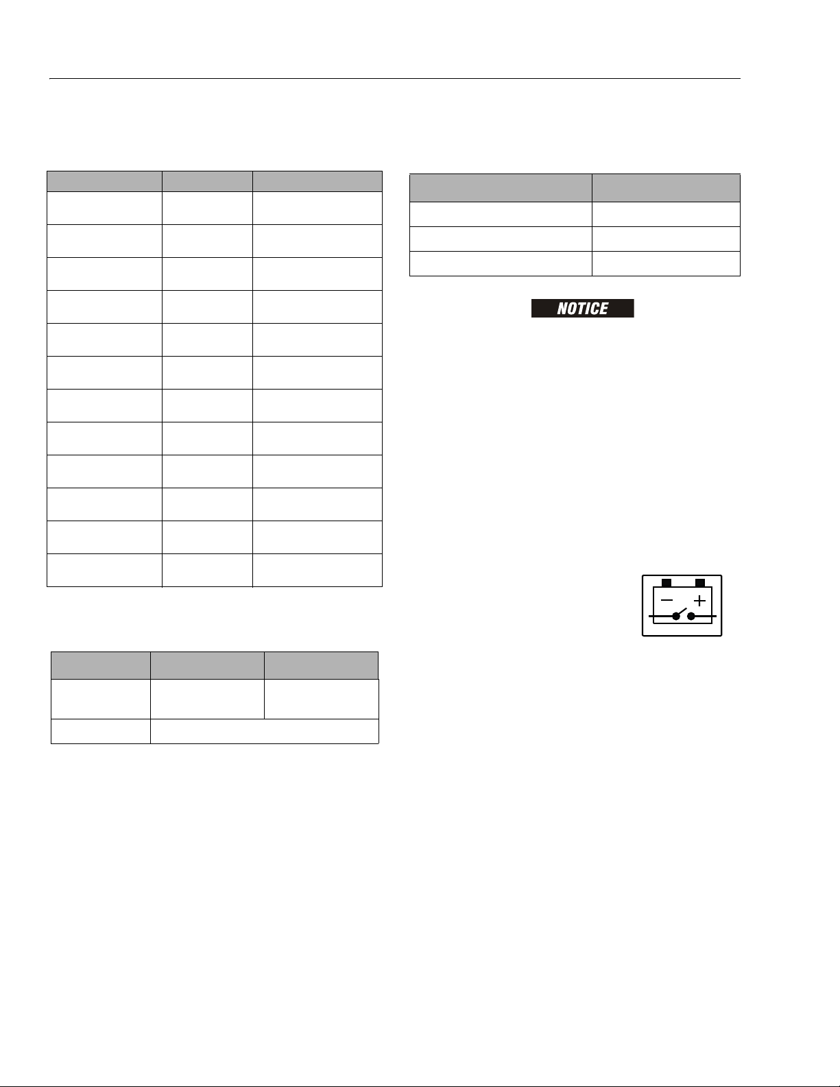
Table 1-5. Battery Specifications
DESCRIPTION ALL MACHINES
Vol tag e (24V-DC System - Series) 6 V per battery
Amp Hour (Standard Battery) 220 Amp Hour @ 20 HR. Rate
Reserve Capacity (Standard Battery) 447 Minutes
JLG MACHINES EQUIPPED WITH DELTA Q BATTERY CHARGERS ARE DESIGNED
FOR THE BEST PERFORMANCE WITH OEM FACTORY APPROVED BATTERIES.
APPROVED JLG REPLACEMENT BATTERIES ARE AVAILABLE THROUGH JLG’S
AFTERMARKET PARTS DISTRIBUTION CENTERS OR JLG'S AFTERMARKET PROGRAMS. FOR ASSISTANCE WITH PROPER BATTERY REPLACEMENT, PLEASE
CONTACT YOUR LOCAL JLG SUPPORT OFFICE.
BATTERIES APPROVED BY JLG HAVE BEEN TESTED FOR COMPATIBILITY WITH
THE ALGORITHM PROGRAMMING OF THE DELTA Q BATTERY CHARGER TO
OPTIMIZE BATTERY LIFE AND MACHINE CYCLE TIMES. THE USE OF NON
APPROVED BATTERIES IN YOUR JLG EQUIPMENT MAY RESULT IN PERFORMANCE ISSUES OR BATTERY CHARGER FAULT CODES. JLG ASSUMES NO
RESPONSIBILITY FOR SERVICE OR PERFORMANCE ISSUES ARISING FROM THE
USE OF NON APPROVED BATTERIES.
Battery Quick-Disconnect (If Equipped)
Machines equipped with the battery
quick-disconnect allow all machine
power to be easily disconnected at the
batteries without removing battery
cables from the battery posts. To disconnect power, locate the
RED quick-disconnect connector on top of the batteries inside
the battery compartment and pull halves apart.
Wheel Bolt Torque 120 ft lb. (163 Nm)
1-2 3121273
Page 15
Electrical System Motors
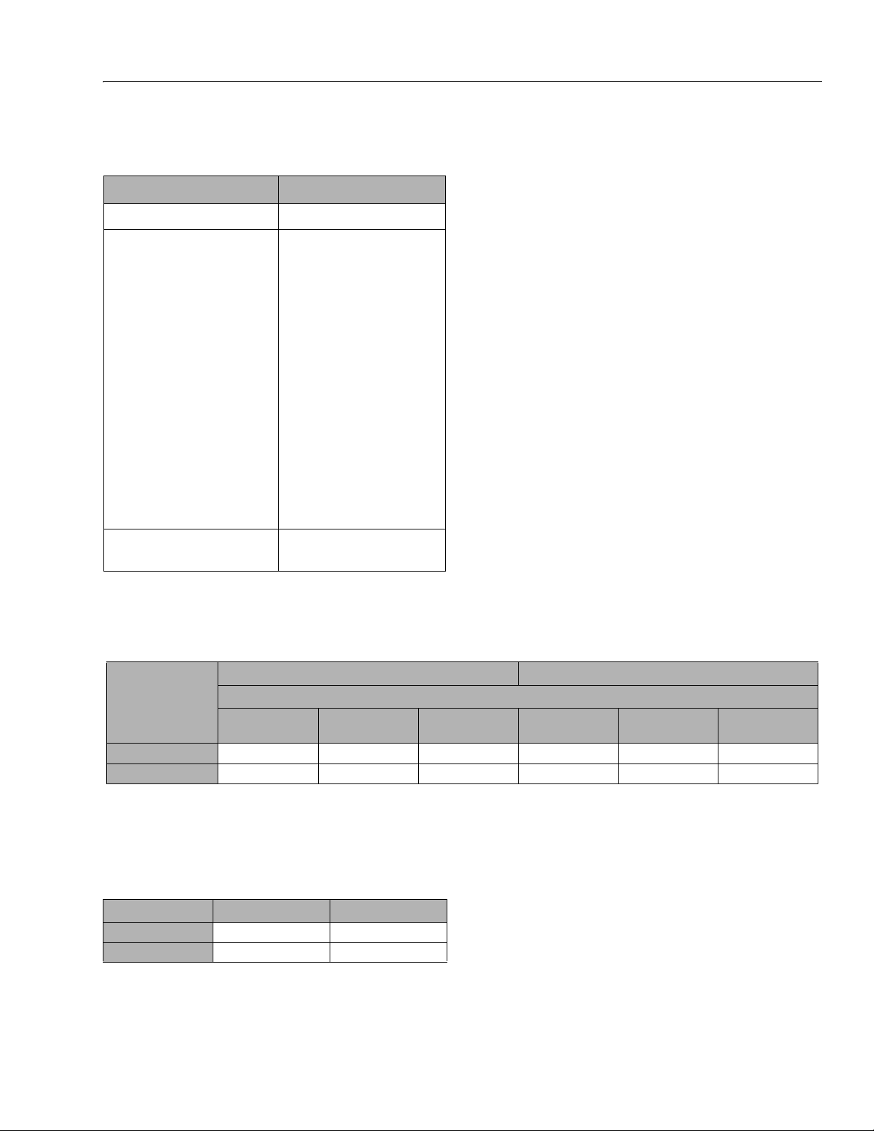
Table 1-6. Electrical System Specifications
DESCRIPTION ALL MACHINES
Electrical System Voltage (DC) 24V - DC
Battery Charger: (1001129847)
Input:
AC Input Voltage:
Nominal AC Input Voltage:
Input Frequency:
Max. AC Input Current:
Ingress Protection:
Operating Temperature:
Output:
Nominal DC Output Voltage:
Ma x . D C O ut p ut Vo l ta g e:
Max DC Output Current:
Max. Interlock Current:
Protection:
Output Reverse Polarity:
Output Short Circuit:
AC Ove rloa d:
DC Overload:
85-265V AC
120VAC / 230VAC RMS
45 - 65Hz
12A - RMS @ 108V AC
IP46 NEMA4 Type 4
-22°F (-30°C) to 122°F (+50°C)
24V
33.6V
25A
1A
Electronic Protection-Auto Reset
Electronic Protection-Auto Reset
Current Limited
Current Limited
• Drive Motor
• Hydraulic Pump/Electric Motor Assembly
(All Models)
SECTION 1 - SPECIFICATIONS
Type: Shunt Wound, Sepex 24V DC
Power: 0.65 Horsepower @ 3750 rpm
Type: Series Wound Permanent Magnet 24V DC
Power: 3kW
DC t o A C I n ve r te r - Ou t pu t Ra t in g :
(OPTION)
120V-AC, 60Hz - 7.5 Amps - 900 Watts Modified Sinewave
Travel Speed
Table 1-7. Travel Speed
ELEVATED SPEED MAXIMUM SPEED (PLATFORM LOWERED)
MODEL
Mph
1932RS/6RS 0.3 59 - 65 0.5 2.5 6.85 - 8.5 4
3246RS/10RS 0.3 57 - 65 0.5 2.5 6.85 - 8.5 4
Sec/25 ft
(Sec/7.6 m)
UNIT OF MEASURE
Kph Mph
Sec/25 ft
(Sec/7.6 m)
Lift Speed
NOTE: Maximum rated load in platform on measured lift speeds. Platform fully raised and lowered.
Table 1-8. Lift Speed
MODEL LIFT UP (SECONDS) LIFT DOWN (SECONDS)
1932RS/6RS 22 - 29 21 - 31
3246RS/10RS 55 - 65 40 - 50
Kph
3121273 1-3
Page 16

SECTION 1 - SPECIFICATIONS
1.2 CRITICAL STABILITY WEIGHTS
DO NOT REPLACE ITEMS CRITICAL TO STABILITY, SUCH AS BATTERIES OR
SOLID TIRES, WITH ITEMS OF DIFFERENT WEIGHT OR SPECIFICATION. DO NOT
MODIFY UNIT IN ANY WAY TO AFFECT STABILITY.
Table 1-9. Critical Stability Weights
COMPON ENT 1932RS/6RS 3248RS/10RS
Wheel and Tire Assembly (e a ch ) F ro nt :
Wheel/Tire and
Drive Assembly (each)
Batteries (each) Standard:
AGM:
Batteries (combined)
Standard :
AGM:
Rear:
21.6 lb. (9.8 kg)
21.6 lb. (9.8 kg)
113 lb. (51.3 kg) 134 lb. (60.8 kg)
43 lb. (19.5 kg)
40.5 lb. (18.4 kg)
62 lb. (28.1 kg)
65 lb. (29.5 kg)
248 lb. (111.1 kg)
260 lb. (118 kg)
1.3 LUBRICATION
Hydraulic Oil
NOTE: Hydraulic oils must have anti-wear qualities at least to API
Service Classification GL-3, and sufficient chemical stability
for mobile hydraulic system service. JLG Industries recommends DTE 10 or Excel 15 hydraulic oil.
Aside from JLG recommendations, it is not advisable to mix
oils of different brands or types, as they may not contain
the same required additives or be of comparable viscosi-
.
ties.
Table 1-10. Hydraulic Oil
HYDRAULIC SYSTEM OPERATING
TEMPERATURE RANGE
0°F to +23°F (-18°C to -5°C) 10W
0°F to 210°F (-18°C to + 99°C) 10W-20, 10W-30
50°F to 210°F (+10°C to +210°C) 20W-20
SAE VISCOSITY GRADE
Table 1-11. Lubrication Specifications
KEY SPECIFICATIONS
EPGL
HO
SPECIFICATION
ISO Viscosity Grade #15 #32 #32
Spec Gravity API 31.9 0.950 —
Pour Point, Max
Flash Point, Min. 330°F (166°C) 514.4 °F (268°C) 478°F (248°C)
at 40°C 15 cSt
at 100°C 4.1 cSt
at 100°F 80 SUS
at 210°F 43 SUS
cp at -30°F 3.2
Viscosity Index 140 147 189
Operating Temp — -20°F (29°C) - 200°F (392°C)
Extreme Pressure Gear Lube (oil) meeting API service classification GL-5 or MIL-Spec MIL-L-2105.
JLG Recommends - Mobil DTE 10, EXCEL 15 or
ATF - Automatic Transmission Fluid
Mobil EAL ENVIRONSYN H 32 (IN U.S.A.)
Mobil EAL HYDRAULIC OIL 32 (IN EUROPE)
Table 1-12. Hydraulic Oil Specifications
MOBIL
DTE 10
EXCEL 15
-40°F
(-40°C)
VISCOSITY SPECIFICATIONS
MOBIL EAL
ENVIRONSYN
H 32
-59°F
(-51°C)
33.1 cSt 32 cSt
6.36 cSt 7 cSt
——
——
——
HYDRAULIC OIL 32
MOBIL EAL
Pressure Settings
Table 1-13. Pressure Settings
MODEL MAIN RELIEF LIFT RELIEF STEER RELIEF
1932RS/6RS
3246RS/10RS
2300 psi
(158 bar)
2500 psi
(172 bar)
2300 psi
(158 bar)
2500 psi
(172 bar)
-38.2°F
(-39°C)
1001102685_3
1000 psi
(69 bar)
1000 psi
(69 bar)
Table 1-11. Lubrication Specifications
KEY SPECIFICATIONS
Multipurpose Grease having a minimum dripping point of 350°F.
MPG
Excellent water resistance and adhesive qualities, and being of
extreme pressure type. (Timken OK 40 pounds minimum.)
1-4 3121273
Page 17
SECTION 1 - SPECIFICATIONS
M12 - 1.5 x 22
22
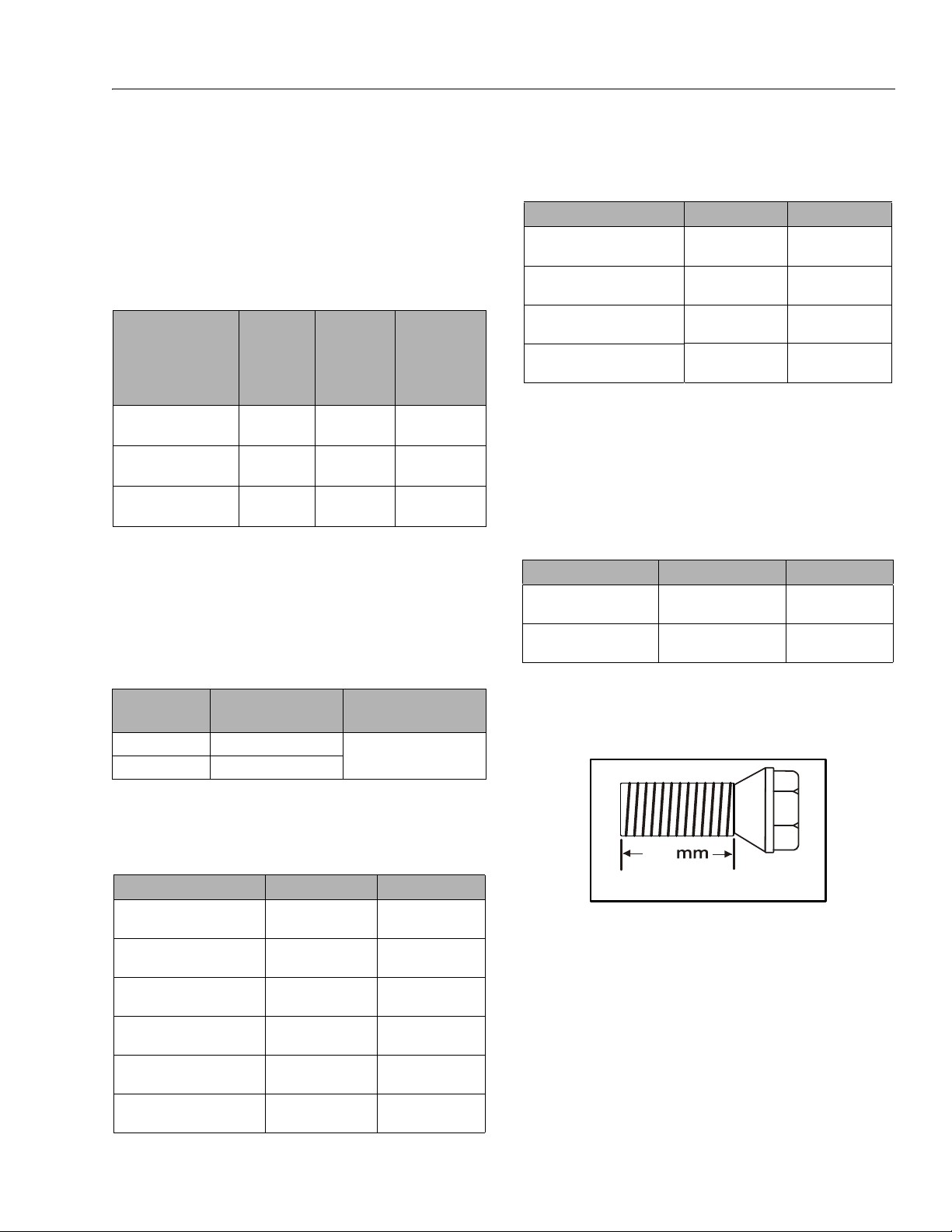
1.4 LIMIT SWITCHES
Tilt Alarm
Illuminates a light on the platform control, sounds an alarm
and cuts out lift up and drive when the machine is out of level
and above stowed depending on model and specifications.
Table 1-14. Tilt Activation Setting
PLATFORM
MODEL
1932RS/6RS - ALL
3248RS/10RS ANSI/CSA/JPN
3248RS/10RS - CE
TILT SETTING
(FRONT TO
BACK)
3° 1.5°
3° 2°
3° 1.5°
TILT SETTING
(SIDE TO SIDE)
High Drive Speed Cutout
High drive speed is cut out @ when the platform is raised
above the preset height per model as follows:
NOTE: These figures are given with a tolerance of ± 6 in. (0.15 m).
Table 1-15. High Drive Cutout Height
MODEL
1932RS/6RS 68.9 in. (1.75m)
3248RS/10RS 88.5 in. (2.25 m)
HIGH DRIVE SPEED
CUTOUT HEIGHT
DRIVE SPEED REDUCTION
ELEVATION
@ TILT
ACTI VATION (± 6
IN.)
69 in.
(1.75 m)
88.5 in.
(2.25 m)
88.5 in.
(2.25 m)
2.5 mph (4 kph) to
0.3 mph (0.5 kph)
1.6 MAJOR COMPONENT WEIGHTS
Table 1-17. Major Component Weights
COMPON ENT 1932RS/6RS 3246RS/10RS
Platform
Manual Platform Extension
Arm Assembly - (Includes Lif t Cylinder)
Chassis w/Wheel/Tire and Drive
Assembly
240 lb.
(109 kg)
115 lb.
(52 kg)
520 lb.
(236 kg)
2,125 lb.
(964 kg)
412 lb.
(187 kg)
150 lb.
68 kg
1,806 lb.
(820 kg)
2,702 lbs
(1226 kg)
1.7 TORQUE REQUIREMENTS
Self locking fasteners, such as nylon insert and thread deforming locknuts, are not intended to be reinstalled after removal.
Always use new replacement hardware when installing locking fasteners.
Table 1-18. Torque Requirements
DESCRIPTION TORQUE VALUE (DRY) INTERVAL HOURS
Front Wheel Spindle Nut
Wheel Bolts
NOTE: Anytime a wheel bolt is replaced, be sure one of the same
length is used. Use bolt shown below on wheels that use
the 1/4" (6.4mm) ring.
30-40 ft lb
(40-54 Nm)
105 -120 ft lb
(142-163 Nm)
50
50
1.5 CYLINDER SPECIFICATIONS
Table 1-16. Cylinder Specifications
DESCRIPTION 1932RS/6RS 3246RS/10RS
Lift Cylinder Bore
Lift Cylinder Stroke
Lift Cylinder Rod Diameter
Steer Cylinder Bore
Steer Cylinder Stroke
Steer Cylinder Rod Diameter
3121273 1-5
2.48 in.
(63 mm)
43.3 in.
(1100 mm)
1.77 in.
(45 mm)
1.5 in.
(38.1 mm)
4.92 in
(125 mm)
0.75m in.
(19.05 mm)
3.93 in.
(100 mm)
48.5 in.
(1232 mm)
2.48 in.
(63 mm)
1.57 in.
(40 mm)
6.77 in.
(172 mm)
0.78 in.
(20 mm)
NOTE: After tightening the spindle nut to the proper torque,
loosen completely until you can turn by hand. Finger
tighten nut by hand without rotating hub. Install cotter pin
by backing nut off, if necessary, in order to line up slot.
When maintenance becomes necessary or a fastener has
loosened, refer to the Torque Charts on page 1-6 to determine proper torque value.
Page 18
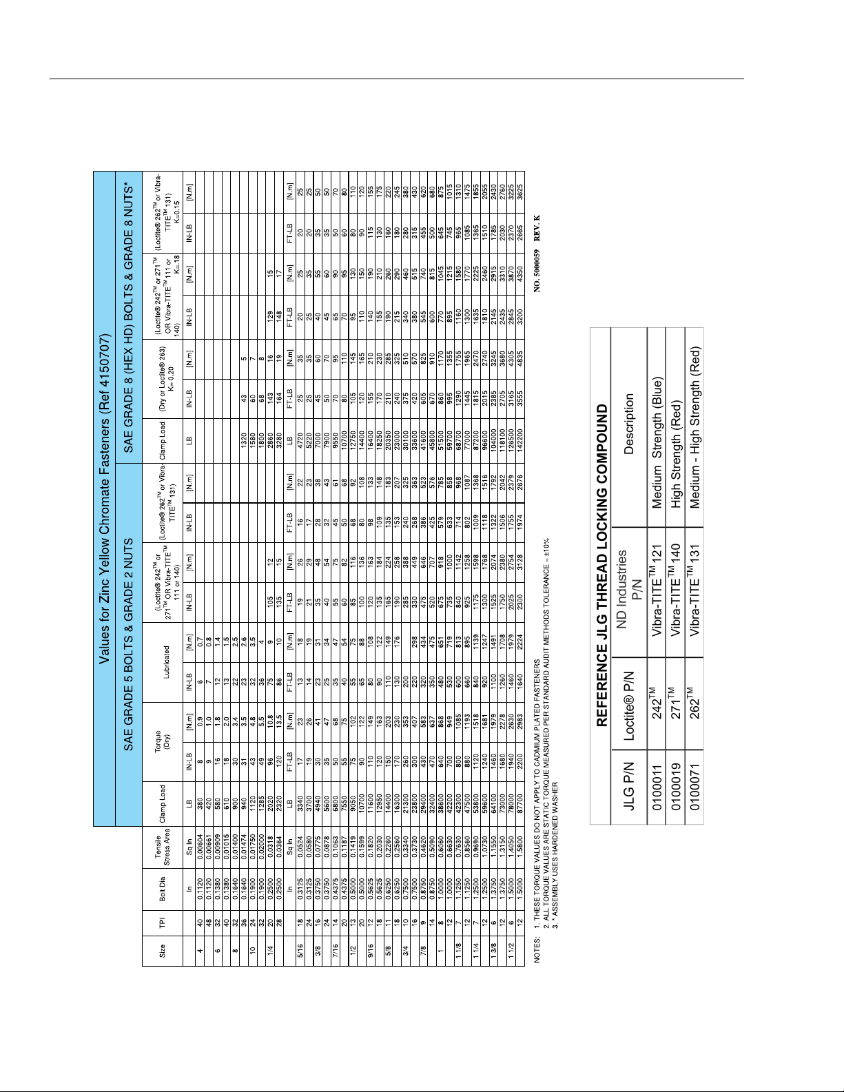
SECTION 1 - SPECIFICATIONS
Figure 1-1. Torque Chart (SAE Fasteners - Sheet 1 of 5)
Tor q u e
To r qu e
Tor q u e
To r qu e
Torque Torque
Torque Charts
1-6 3121273
Page 19
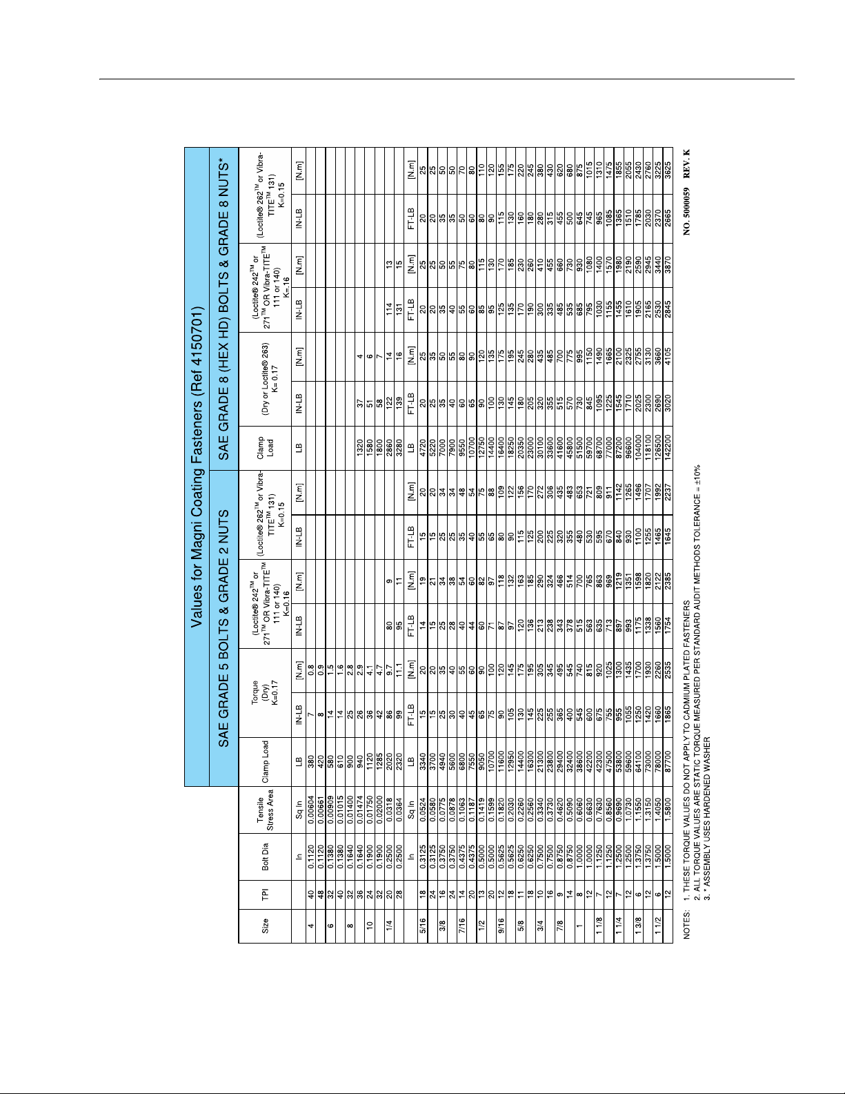
SECTION 1 - SPECIFICATIONS
Tor q u e
Tor q ue
Tor q ue
Tor qu e
To r qu e
Figure 1-2. Torque Chart (SAE Fasteners - Sheet 2 of 5)
3121273 1-7
Page 20
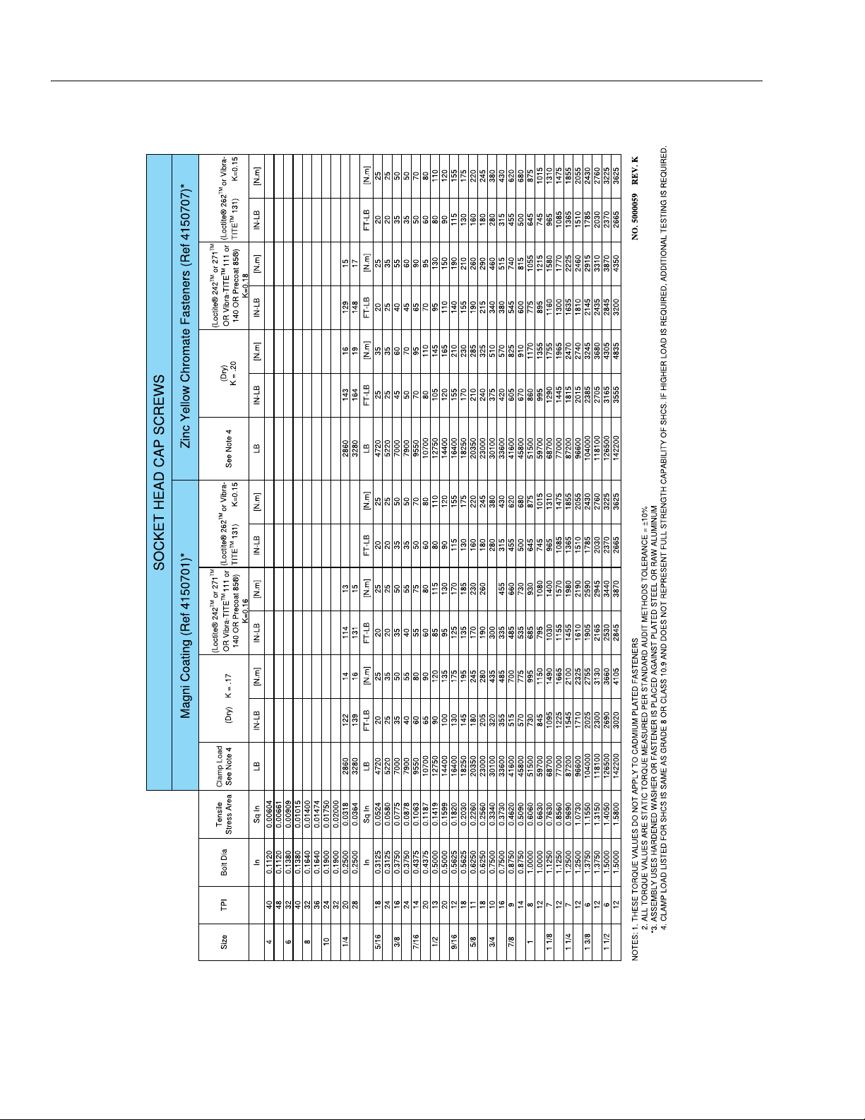
SECTION 1 - SPECIFICATIONS
Figure 1-3. Torque Chart (SAE Fasteners - Sheet 3 of 5)
Clamp LoadTo r qu e
To r qu e
Tor q u e
Torque
Tor qu e
Tor q u e
1-8 3121273
Page 21
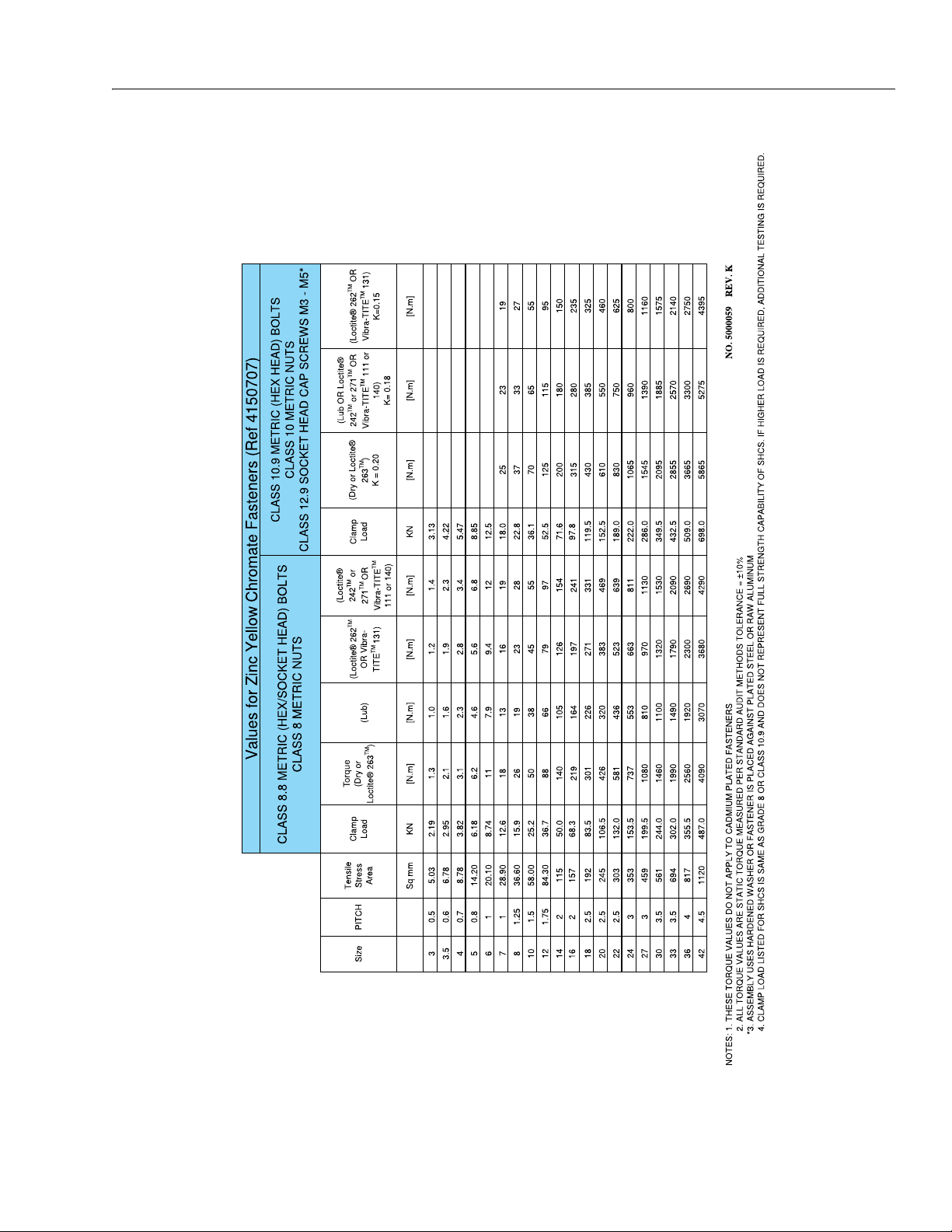
SECTION 1 - SPECIFICATIONS
Figure 1-4. Torque Chart (Metric Fasteners - Sheet 4 of 5)
To r qu e
To r qu e
Torque
To r q ue
To r qu e
To r q ue
3121273 1-9
Page 22
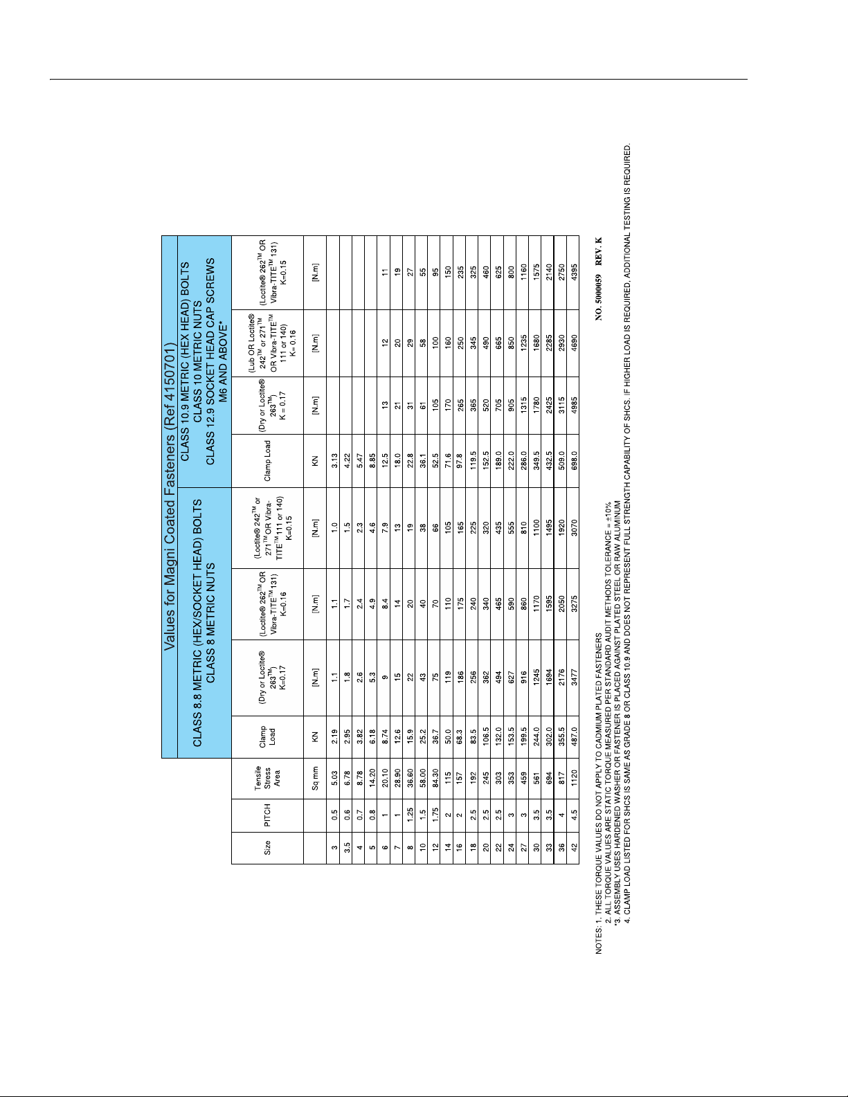
SECTION 1 - SPECIFICATIONS
Figure 1-5. Torque Chart (Metric Fasteners - Sheet 5 of 5)
Torq ue Torque
Tor qu e
To r qu e
To r qu e
To r q ue
1-10 3121273
Page 23

SECTION 2. GENERAL
SECTION 2 - GENERAL
2.1 MACHINE PREPARATION, INSPECTION, AND MAINTENANCE
General
This section provides the necessary information needed by
those personnel that are responsible to place the machine in
operation readiness and maintain its safe operating condition.
For maximum service life and safe operation, ensure that all
the necessary inspections and maintenance have been completed before placing the machine into service. With proper
care, maintenance and inspections performed per JLG's recommendations with any and all discrepancies corrected, this
product will be fit for continued use.
Preparation, Inspection, and Maintenance
It is important to establish and conform to a comprehensive
inspection and preventive maintenance program. The following table outlines the periodic machine inspections and maintenance recommended by JLG Industries, Inc. Consult your
national, regional, or local regulations for further requirements
for aerial work platforms. The frequency of inspections and
maintenance must be increased as environment, severity and
frequency of usage requires.
Pre-Start Inspection
Reference the JLG Pre-Delivery and Frequent Inspection Form
and the Inspection and Preventative Maintenance Schedule
for items requiring inspection during the performance of
these inspections. Reference the appropriate areas of this
manual for servicing and maintenance procedures.
Annual Machine Inspection
JLG recommends that the Annual Machine Inspection be performed by a Factory-Trained Service Technician on an annual
basis, no later than thirteen (13) months from the date of the
prior Annual Machine Inspection. JLG Industries, Inc. recognizes a Factory-Trained Service Technician as a person who has
successfully completed the JLG Service Training School for the
subject JLG product model. Reference the machine Service
and Maintenance Manual and appropriate JLG inspection
form for performance of this inspection.
Reference the JLG Annual Machine Inspection Form and the
Inspection and Preventative Maintenance Schedule for items
requiring inspection during the performance of this inspection. Reference the appropriate areas of this manual for servicing and maintenance procedures.
For the purpose of receiving safety-related bulletins, it is
important that JLG Industries, Inc. has updated ownership
information for each machine. When performing each Annual
Machine Inspection, notify JLG Industries, Inc. of the current
machine ownership.
It is the User’s or Operator’s primary responsibility to perform a
Pre-Start Inspection of the machine prior to use daily or at
each change of operator. Reference the Operation and Safety
Manual for completion procedures for the Pre-Start Inspection. The Operation and Safety Manual must be read in its
entirety and understood prior to performing the Pre-Start
Inspection.
Pre-Delivery Inspection and Frequent Inspection
The Pre-Delivery Inspection and Frequent Inspection shall be
performed by a qualified JLG equipment mechanic. JLG Industries, Inc. recognizes a qualified JLG equipment mechanic as a
person who, by possession of a recognized degree, certificate,
extensive knowledge, training, or experience, has successfully
demonstrated the ability and proficiency to service, repair, and
maintain the subject JLG product model.
The Pre-Delivery Inspection and Frequent Inspection procedures are performed in the same manner, but at different
times. The Pre-Delivery Inspection shall be performed prior to
each sale, lease, or rental delivery. The Frequent Inspection
shall be accomplished for each machine in service for 3
months or 150 hours (whichever comes first); out of service for
a period of more than 3 months; or when purchased used. The
frequency of this inspection must be increased as environment, severity and frequency of usage requires.
Preventative Maintenance
In conjunction with the specified inspections, maintenance
shall be performed by a qualified JLG equipment mechanic.
JLG Industries, Inc. recognizes a qualified JLG equipment
mechanic as a person who, by possession of a recognized
degree, certificate, extensive knowledge, training, or experience, has successfully demonstrated the ability and proficiency to service, repair, and maintain the subject JLG product
model.
Reference the Preventative Maintenance Schedule and the
appropriate areas of this manual for servicing and maintenance procedures. The frequency of service and maintenance
must be increased as environment, severity and frequency of
usage requires.
3121273 2-1
Page 24

SECTION 2 - GENERAL
Table 2-1. Inspection and Maintenance Responsibilities
Type Frequency
Pre-Start
Inspection
Pre-Deliver y
Inspection
Frequent
Inspection
Annual Machine
Inspection Annually, no later than 13 months from the date of the prior inspection. Owner, Dealer, or User
Preventative Main-
tenance
In service for 3 months or 150 hours, whichever comes first; or Out of
service for a period of more than 3 months; or Purchased used.
At intervals as specified in the Service and Maintenance Manual. Owner, Dealer, or User Qualified JLG Mechanic Service and Maintenance Manual
Prior to use each day; or
At each Operator change.
Prior to each sale, lease, or
rental d elivery.
Primary
Responsibility
User or Operator User or Operator Operation and Safety Manual
Owner, Dealer, or User Qualified JLG Mechanic
Owner, Dealer, or User Qualified JLG Mechanic
2.2 PREVENTIVE MAINTENANCE AND INSPECTION SCHEDULE
The preventive maintenance and inspection checks are listed
and defined in the following table. This table is divided into
two basic parts, the “AREA” to be inspected and the “INTERVAL” at which the inspection is to take place. Under the “AREA”
portion of the table, the various systems along with the components that make up that system are listed. The “INTERVAL”
portion of the table is divided into two columns representing
the various inspection time periods. The numbers listed within
the interval column represent the applicable inspection code
for which that component is to be checked.
The checks and services listed in this schedule are not
intended to replace any local or regional regulations that may
pertain to this type of equipment nor should the lists be considered as all inclusive. Variances in interval times may occur
due to climate and/or conditions and depending on the location and use of the machine.
JLG INDUSTRIES REQUIRES THAT A COMPLETE ANNUAL INSPECTION BE PERFORMED IN ACCORDANCE WITH THE "ANNUAL MACHINE INSPECTION
REPORT" FORM.
NOTE: This machine requires periodic safety and maintenance
inspections by a qualified JLG mechanic. Notify JLG dealer
if inspection is overdue.
10. Decals installed and legible.
11. Check for proper fluid level.
12. Check for chafing and proper routing.
13. Check for proper tolerances.
14. Properly lubricated.
15. Torqued to proper specification.
16. No gouges, excessive wear, or cords showing.
17. Properly inflated and seated around rim.
18. Proper and authorized components.
19. Fully charged.
20. No loose connections, corrosion, or abrasions.
21. Verify.
22. Perform.
23. Sealed properly.
24. Overrides Platform controls.
25. Remove pump motor cover and blow away any brush
Service
Qualification
Service and Maintenance Manual and
Service and Maintenance Manual and
Fac tor y-Tra ined
Service Technician
(recommended)
6. Returns to neutral or "off" position when released.
7. Clean and free of debris.
8. Interlocks function properly.
9. Check for signs of leakage.
wear dust from cover, brushes, and brush holder assembly.
Service and Maintenance Manual and
Reference
applicable JLG inspection form.
applicable JLG inspection form.
applicable JLG inspection form.
Maintenance and Inspection Schedule Codes:
1. Check for proper and secure installation.
2. Visual inspection for damage, cracks, distortion, or exces-
sive wear.
3. Check for proper adjustment.
4. Check for cracked or broken welds.
5. Operates properly.
Footnotes:
(a) Prior to each sale, lease, or delivery
(b) In service for 3 months; or Out of service for 3 months
or more; or Purchased used
(c) Annually, no later than 13 months from the date of the
prior inspection
2-2 3121273
Page 25

Table 2-2. Preventive Maintenance & Inspection Schedule.
INTERVAL
SECTION 2 - GENERAL
AREA ON MACHINE
FUNCTIONS/CONTROLS
Platform Controls 5, 6, 7 5, 6, 7
Ground Controls 5, 6 5, 6, 14
Function Control Locks, Guards, or Detents 5 5
Function Enable System 5 5
Emergency Stop Switches (Ground & Platform) 5 5
Function Limit or Cutout Switch Systems 5 5
Manual Descent or Auxiliary Power 5 5
PLATFORM ASSEMBLY
Platform 1 1
Guard Rails 1, 2, 4 1, 2, 4
Gate 1, 5 1, 5
Floor 1, 2 1, 2
Lanyard Anchorage Point 1, 4, 10 1, 4, 10
SCISSOR ARMS
Scissor Arms 1, 2, 4 1, 2, 4
Arm Safety Prop 1, 5 1, 5
Cylinder Pins, Pivot Pins & Attaching Hardware 1 1
Arm Pins, Wear Pads & Att aching H ardware 1 1
CHASSIS ASSEMBLY
Covers Insta llati on 1, 7 1 , 7
Static Strap 1 1
Wheel and Tire Assemblies 2, 15 2, 15
Drive Motors 1, 7, 9 1, 7, 9
Drive Motor Brushes ** — —
POWER SYSTEM
Batteries 9 18
Battery Charger 5
HYDRAULIC/ELECTRIC SYSTEM
Hydraulic Lift/Steer Pump 1, 2, 9 1, 2, 5, 9, 25
Hydraulic Cylinders (arms and steering) 2, 7, 9 2, 9
Steer Cylinder Attachment Pins and Pin Retainers 1, 2 1, 2
Hydraulic Hoses, Lines, and Fittings 1, 9 1, 9
Hydraulic Reservoir, Cap, and Breather 5, 7 5, 7
Hydraulic Fluid *** 11 11
Electrical Connections 20 20
Instruments, Gauges, Switches, Lights, Horn 5 5
PRE-DELIVERY (a)
OR FREQUENT (b)
INSPECTION
ANNUAL (c)
(YEARLY)
INSPECTION
3121273 2-3
Page 26

SECTION 2 - GENERAL
GENERAL
Operation & Safety Manual in Storage Box 21 21
ANSI & EMI Handbooks in Storage Box (ANSI ONLY) 21 21
Capacity Decals Installed, S ecure, Legi ble 21 2 1
All Decals/Placards Installed, Secure, Legible 21 21
Annual Machine Inspection Due 21
No Unauthorized Modifications or Additions 21 21
All Relevant Safety Publications Incorporated 21 21, 22
General Structural Condition an d Welds 2, 4 2, 4
All Fasteners, Pins, Shields, and Covers 1, 2
Grease and Lubricate to Specifications 22 22
Function Test of All Systems 22 22
Paint and Appearance 7 7
Notify JLG of change in Machine Ownership 22
Table 2-2. Preventive Maintenance & Inspection Schedule. (Continued)
INTERVAL
AREA ON MACHINE
PRE-DELIVERY (a)
OR FREQUENT (b)
INSPECTION
ANNUAL (c)
(YEARLY)
INSPECTION
** Replace when system performance is degraded.
*** Every two years, drain and remove hydraulic oil reservoir , clean pick-up screen, refill with fresh hydraulic fluid.
2-4 3121273
Page 27

SECTION 2 - GENERAL
2.3 SERVICE AND GUIDELINES
General
The following information is provided to assist you in the use
and application of servicing and maintenance procedures
contained in this book.
Safety and Workmanship
Your safety, and that of others, is the first consideration when
engaging in the maintenance of equipment. Always be conscious of weight. Never attempt to move heavy parts without
the aid of a mechanical device. Do not allow heavy objects to
rest in an unstable position. When raising a portion of the
equipment, ensure that adequate support is provided.
Cleanliness
1. The most important single item in preserving the long
service life of a machine is to keep dirt and foreign materials out of the vital components. Precautions have been
taken to safeguard against this. Shields, covers, seals,
and filters are provided to keep air, fuel, and oil supplies
clean; however, these items must be maintained on a
scheduled basis in order to function properly.
2. At any time when air, fuel, or oil lines are disconnected,
clean adjacent areas as well as the openings and fittings
themselves. As soon as a line or component is disconnected, cap or cover all openings to prevent entry of foreign matter.
3. Clean and inspect all parts during servicing or maintenance, and assure that all passages and openings are
unobstructed. Cover all parts to keep them clean. Be
sure all parts are clean before they are installed. New
parts should remain in their containers until they are
ready to be used.
Component Disassembly and Reassembly
When disassembling or reassembling a component, complete
the procedural steps in sequence. Do not partially disassemble
or assemble one part, then start on another. Always recheck
your work to assure that nothing has been overlooked. Do not
make any adjustments, other than those recommended, without obtaining proper approval.
Pressure-Fit Parts
When assembling pressure-fit parts, use an anti-seize or
molybdenum disulfide base compound to lubricate the mating surface.
Bearings
1. When a bearing is removed, cover it to keep out dirt and
abrasives. Clean bearings in nonflammable cleaning solvent and allow to drip dry. Compressed air can be used
but do not spin the bearing.
2. Discard bearings if the races and balls (or rollers) are pitted, scored, or burned.
3. If bearing is found to be serviceable, apply a light coat of
oil and wrap it in clean (waxed) paper. Do not unwrap
reusable or new bearings until they are ready to install.
4. Lubricate new or used serviceable bearings before
installation. When pressing a bearing into a retainer or
bore, apply pressure to the outer race. If the bearing is to
be installed on a shaft, apply pressure to the inner race.
Gaskets
Check that holes in gaskets align with openings in the mating
parts. If it becomes necessary to hand-fabricate a gasket, use
gasket material or stock of equivalent material and thickness.
Be sure to cut holes in the right location, as blank gaskets can
cause serious system damage.
Bolt Usage and Torque Application
Components Removal and Installation
1. Use adjustable lifting devices, whenever possible, if
mechanical assistance is required. All slings (chains,
cables, etc.) should be parallel to each other and as near
perpendicular as possible to top of part being lifted.
2. Should it be necessary to remove a component on an
angle, keep in mind that the capacity of an eyebolt or
similar bracket lessens, as the angle between the supporting structure and the component becomes less
than 90°.
3. If a part resists removal, check to see whether all nuts,
bolts, cables, brackets, wiring, etc., have been removed
and that no adjacent parts are interfering.
1. Self locking fasteners, such as nylon insert and thread
deforming locknuts, are not intended to be reinstalled
after removal. Always use new replacement hardware
when installing locking fasteners.
2. Use bolts of proper length. A bolt which is too long will
bottom before the head is tight against its related part. If
a bolt is too short, there will not be enough thread area
to engage and hold the part properly. When replacing
bolts, use only those having the same specifications of
the original, or one which is equivalent.
3. Unless specific torque requirements are given within the
text, standard torque values should be used on heattreated bolts, studs, and steel nuts, in accordance with
recommended shop practices. (See Torque Chart Section 1.)
3121273 2-5
Page 28

SECTION 2 - GENERAL
Hydraulic Lines and Electrical Wiring
Clearly mark or tag hydraulic lines and electrical wiring, as well
as their receptacles, when disconnecting or removing them
from the unit. This will assure that they are correctly reinstalled.
Hydraulic System
1. Keep the system clean. If evidence of metal or rubber
particles are found in the hydraulic system, drain and
flush the entire system.
2. Disassemble and reassemble parts on a clean work surface. Clean all metal parts with non-flammable cleaning
solvent. Lubricate components, as required, to aid
assembly.
Lubrication
Service applicable components with the amount, type, and
grade of lubricant recommended in this manual, at the specified intervals. When recommended lubricants are not available, consult your local supplier for an equivalent that meets
or exceeds the specifications listed.
Battery
Clean battery, using a non-metallic brush and a solution of
baking soda and water. Rinse with clean water. After cleaning,
thoroughly dry battery and coat terminals with an anti corrosion compound.
2.4 LUBRICATION AND INFORMATION
Hydraulic System
1. The primary enemy of a hydraulic system is contamination. Contaminants enter the system by various means,
e.g., using inadequate hydraulic oil, allowing moisture,
grease, filings, sealing components, sand, etc., to enter
when performing maintenance, or by permitting the
pump to cavitate due to insufficient quantity of oil in
supply tube.
2. The design and manufacturing tolerances of the component working parts are very close, therefore, even the
smallest amount of dirt or foreign matter entering a system can cause wear or damage to the components and
generally results in faulty operation. Every precaution
must be taken to keep hydraulic oil clean, including
reserve oil in storage. Hydraulic system filters should be
checked, cleaned, and/or replaced as necessary, at the
specified intervals required. Always examine filters for
evidence of metal particles.
3. Cloudy oils indicate a high moisture content which permits organic growth, resulting in oxidation or corrosion.
If this condition occurs, the system must be drained,
flushed, and refilled with clean oil.
4. It is not advisable to mix oils of different brands or types,
as they may not contain the same required additives or
be of comparable viscosities. Good grade mineral oils,
with viscosities suited to the ambient temperatures in
which the machine is operating, are recommended for
use.
NOTE: Metal particles may appear in the oil or filters of new
machines due to the wear-in of meshing components.
Hydraulic Oil
1. Refer to Section 1 for recommendations for viscosity
ranges.
2. JLG recommends DTE10 or Excel 15 hydraulic oil, which
has an SAE viscosity of 10W-30 and a viscosity index of
152.
NOTE: Start-up of hydraulic system with oil temperatures below -
15°F (-26°C) is not recommended. If it is necessary to start
the system in a sub-zero environment, it will be necessary
to heat the oil with a low density, electrical heater to a minimum temperature of -15°F (-26°C).
2-6 3121273
Page 29

SECTION 2 - GENERAL
Changing Hydraulic Oil
1. Use of any of the recommended crankcase or hydraulic
oils eliminates the need for changing the oil on a regular
basis. However, filter elements must be changed annually unless operating in extreme conditions. If it is necessary to change the oil, use only those oils meeting or
exceeding the specifications appearing in this manual. If
unable to obtain the same type of oil supplied with the
machine, consult local supplier for assistance in selecting the proper equivalent. Avoid mixing petroleum and
synthetic base oils. JLG Industries recommends changing the hydraulic oil annually.
2. Use every precaution to keep the hydraulic oil clean. If
the oil must be poured from the original container into
another, be sure to clean all possible contaminants from
the service container. Always replace the filter and clean
magnet any time the system oil is changed.
3. While the unit is shut down, a good preventive maintenance measure is to make a thorough inspection of all
hydraulic components, lines, fittings, etc., as well as a
functional check of each system, before placing the
machine back in service.
NOTE: Refer to section 4 for oil checking and oil changing proce-
dure.
Lubrication Specifications
2.5 CYLINDER DRIFT TEST
Maximum acceptable cylinder drift is to be measured using
the following methods.
Platform Drift
Measure the drift of the platform to the ground. Fully extend
the scissor arms from stowed position with the rated load in
the platform and power off. Maximum allowable drift is 2 in (5
cm) in 10 minutes. If the machine does not pass this test, proceed with the following.
Cylinder Drift
Table 2-3. Cylinder Drift
CYLINDER BORE DIAMETER
inches mm inches mm
3 76.2 0.026 0.66
3.5 89 0.019 0.48
4 101.6 0.015 0.38
5 127 0.009 0.22
6 152.4 0.006 0.15
7 177.8 0.005 0.13
MAX. ACCEPTABLE DRIFT
IN 10 MINUTES
Specified lubricants, as recommended by the component
manufacturers, are always the best choice, however, multi-purpose greases usually have the qualities which meet a variety of
single purpose grease requirements. Should any question
arise, regarding the use of greases in maintenance stock, consult your local supplier for evaluation. Refer to Section 1, Table
1-11, Lubrication Specifications for an explanation of the lubricant key designations.
Drift is to be measured at the cylinder rod with a calibrated
dial indicator. The cylinder oil must be at ambient temperature
and temperature stabilized.
The cylinder must have the normal load, which is the normal
platform load applied.
If the cylinder passes this test, it is acceptable.
NOTE:
This information is based on 6 drops per minute cylinder leakage.
3121273 2-7
Page 30

SECTION 2 - GENERAL
2.6 PINS AND COMPOSITE BEARING REPAIR GUIDELINES
Filament wound bearings.
1. Pinned joints should be disassembled and inspected if
the following occurs:
a. Excessive sloppiness in joints.
b. Noise originating from the joint during operation.
2. Filament wound bearings should be replaced if any of
the following is observed:
a. Frayed or separated fibers on the liner surface.
b. Cracked or damaged liner backing.
c. Bearings that have moved or spun in their housing.
d. Debris embedded in liner surface.
3. Pins should be replaced if any of the following is
observed (pin should be properly cleaned prior to
inspection):
a. Detectable wear in the bearing area.
b. Flaking, pealing, scoring, or scratches on the pin sur-
face.
c. Rusting of the pin in the bearing area.
4. Re-assembly of pinned joints using filament wound
bearings.
a. Housing should be blown out to remove all dirt and
debris, bearings and bearing housings must be free
of all contamination.
b. Bearing / pins should be cleaned with a solvent to
remove all grease and oil...filament wound bearings
are dry joints and should not be lubricated.
c. Pins should be inspected to ensure it is free of burrs,
nicks, and scratches which would damage the bearing during installation and operation.
2-8 3121273
Page 31

3.1 MACHINE COMPONENT COVERS
1
2
3
2
4
SECTION 3 - CHASSIS & SCISSOR ARMS
SECTION 3. CHASSIS & SCISSOR ARMS
1. Left Side (Hydraulic) Frame Cover
2. Side Cover Release Handles
3121273 3-1
Figure 3-1. Machine Frame Covers (All Models)
3. Right Side (Batteries) Frame Cover
4. Rear (Drive Motor/Charger/Control Module) Cover
Page 32

SECTION 3 - CHASSIS & SCISSOR ARMS
1706740A
1
2
3
3
3.2 BATTERY REMOVAL/MAINTENANCE
JLG MACHINES EQUIPPED WITH DELTA Q BATTERY CHARGERS ARE DESIGNED
FOR THE BEST PERFORMANCE WITH OEM FACTORY APPROVED BATTERIES.
APPROVED JLG REPLACEMENT BATTERIES ARE AVAILABLE THROUGH JLG'S
AFTERMARKET PARTS DISTRIBUTION CENTERS OR JLG'S AFTERMARKET PROGRAMS. FOR ASSISTANCE WITH PROPER BATTERY REPLACEMENT, PLEASE
CONTACT YOUR LOCAL JLG SUPPORT OFFICE.
BATTERIES APPROVED BY JLG HAVE BEEN TESTED FOR COMPATIBILITY WITH
THE ALGORITHM PROGRAMMING OF THE DELTA Q BATTERY CHARGER TO
OPTIMIZE BATTERY LIFE AND MACHINE CYCLE TIMES. THE USE OF NON
APPROVED BATTERIES IN YOUR JLG EQUIPMENT MAY RESULT IN PERFORMANCE ISSUES OR BATTERY CHARGER FAULT CODES. JLG ASSUMES NO
RESPONSIBILITY FOR SERVICE OR PERFORMANCE ISSUES ARISING FROM THE
USE OF NON APPROVED BATTERIES.
Battery Quick-Disconnect (If Equipped)
Machines equipped with the battery
quick-disconnect allow all machine
power to be easily disconnected at the
batteries without removing battery cables from the battery
posts. To disconnect power, locate the RED quick-disconnect
connector on top of the batteries inside the battery compartment and pull halves apart.
Figure 3-2. Battery Location and Hold Down Bar
(All Models)
1. Batteries (4 - 6V)
2. Hold-Dow n Bar
3. Hold-Down Bar Fasteners
Battery Maintenance and Safety Practices
BEFORE BATTERY REMOVAL CAN BEGIN, ENSURE THAT THE (+) AND (–) BATTERY CABLES HAVE BEEN PROPERLY DISCONNECTED.
1. The machine batteries are located inside the machine
right side cover, remove the cover.
2. Once the battery door is removed from the machine,
battery replacement/maintenance can begin.
3. To remove one or more batteries from the machine, the
battery hold down bar will need to be removed. (See
Figure 3-2.)
4. Remove the (2) nuts and washers from each hold-down
anchor at the ends of the hold-down bar. Remove the
bar and lay aside.
5. After battery removal and installation re-install the battery hold down bar.
6. After any maintenance on the batteries or replacement
of the batteries is complete, reconnect the batteries and
check for proper operation.
7. Re-install the machine right side cover.
ENSURE THAT BATTERY ACID DOES NOT COME INTO CONTACT WITH SKIN OR
CLOTHING. WEAR PROTECTIVE CLOTHING AND EYEWEAR WHEN WORKING
WITH BATTERIES. NEUTRALIZE ANY BATTERY ACID SPILLS WITH BAKING
SODA AND WATER.
BATTERY ACID RELEASES AN EXPLOSIVE GAS WHILE CHARGING, ALLOW NO
OPEN FLAMES, SPARKS OR LIGHTED TOBACCO PRODUCTS IN THE AREA WHILE
CHARGING BATTERIES. CHARGE BATTERIES ONLY IN A WELL VENTILATED
AREA.
ADD ONLY DISTILLED WATER TO BATTERIES. WHEN ADDING WATER TO THE
BATTERIES, A NON-METALLIC CONTAINER AND/OR FUNNEL MUST BE USED.
DO NOT REPLACE ITEMS CRITICAL TO STABILITY, SUCH AS BATTERIES, WITH
ITEMS OF DIFFERENT WEIGHT OR SPECIFICATION. DO NOT MODIFY UNIT IN
ANY WAY TO AFFECT STABILITY.
3-2 3121273
Page 33

Check the electrolyte level of the batteries often, adding only
BATTERY
FILLER CAP
FLUID LEVEL OF FULLY
CHARGED BATTERY
VENT TUBE
PLATES
1/8 "
Figure 3-3. Battery Fluid Level
1
2
3
distilled water when required. When fully charged, battery
fluid level should be 1/8" below vent tubes. (See Figure 3-3.).
• DO NOT fill to bottom of vent tubes.
• DO NOT allow fluid level to go below the top of the plates
when charging or operating.
• Clean terminal connections if they become corroded.
SECTION 3 - CHASSIS & SCISSOR ARMS
3.3 BATTERY CHARGER
The Battery Charger is located at the rear of the machine
under the rear access cover, remove the cover to gain access to
the charger.
Battery Charger Location
1. AC Voltage - Input Cable
3. DC Power Cable to Batteries
2. Charger Interlock Cable
Figure 3-4. Battery Charger (Delta Q)
Table 3-1. Battery Charger Specs (Delta Q)
BATTERY CHARGER SPECIFICATION
OUTPUT
Nominal DC Output Voltage 24V
Maximum DC Output Voltage 33.6V
Maximum DC Output Current 25A
Maximum Interlock Current 1A
INPUT
AC Input Voltage 85-265VAC
Nominal AC Input Voltage 120VAC - 230VAC RMS
AC Input Frequency 45-65 HZ
Maximum AC Input Current 12A RMS@108VAC
OPERATION
Charging Indicator Yellow LED
Battery Fault Indicator Flashing Yellow LED
100% Charge Indicator Green LED
Charger Fault Indicator Red LED
PROTECTION
Output Reverse Polarity Electronic Protection - Automatic Reset
Output Short Circuit Electronic Protection - Automatic Reset
AC Overload Current Limited
DC Overload Current Limited
MECHANICAL
Operating Temperature
–22° F to +122°F
(–30°C to +50°C)
Housing Shock and Water Resistant Aluminum
3121273 3-3
Page 34

SECTION 3 - CHASSIS & SCISSOR ARMS
1
2
MAF03000
GREEN (ON) Battery Fully Charged
AMBER (ON) Battery Charging
AMBER (FLASHING) Battery/System
Problem
RED (FLASHING) Charger Problem
GREEN
AMBER
RED
LEDS
1. Power connector 2. Charger Interlock Cable
Figure 3-5. Battery Charger (Green Power)
3.4 BATTERY CHARGING
NOTE: Be sure that machine is parked in a well ventilated area
before charging begins.
ONLY PLUG THE CHARGER INTO A PROPERLY INSTALLED AND GROUNDED
OUTLET. DO NOT USE GROUND ADAPTORS OR MODIFY PLUG. DO NOT TOUCH
NON-INSULATED PORTION OF OUTPUT CONNECTOR OR NON-INSULATED BATTERY TERMINAL.
DO NOT OPERATE CHARGER IF THE AC SUPPLY CORD IS DAMAGED OR IF THE
CHARGER HAS RECEIVED A SHARP BLOW, BEEN DROPPED, OR OTHERWISE
DAMAGED IN ANY WAY.
ALWAYS DISCONNECT THE CHARGER AC SUPPLY BEFORE MAKING OR BREAKING THE (POS/NEG) CONNECTIONS TO THE BATTERY.
DO NOT OPEN OR DISASSEMBLE CHARGER.
Table 3-2. Battery Charger (Green Power)
BATTERY CHARGER SPECIFICATION
OUTPUT
Nominal DC Output Voltage 24V
Maximum DC Output Voltage 34V
Maximum DC Output Current 30A
INPUT
AC Input Voltage 100-240V
AC Input Frequency 45-65 HZ
Maximum AC Input Current 8.5A
OPERATION
Charging Indicator Yellow LED
100% Charge Indicator Green LED
1. The battery charger AC input plug is located in an opening on the panel at the lower rear of the machine.
2. Connect the charger AC input plug to a grounded outlet
using a 3 wire heavy duty extension cord. (See Table 3-1,
Battery Charger Specs (Delta Q), for battery charger AC
input specifications.)
3. When powered up the charger will go through a short
LED indicator self-test. The battery charger LED indicators on the charger (Figure 3-6.), will flash in sequence for
two seconds. These LED indicators can be viewed
through the opening on the rear panel where the charger AC cord is accessed.
4. The batteries are fully charged when the green light on
the battery charger status panel is illuminated.
NOTE: If the charger is left plugged in, the charger will automati-
cally restart a complete charge cycle if the batteries voltage
drops below a minimum voltage or 30 days has elapsed.
3-4 3121273
Figure 3-6. Charger Decal LED Indicators
Page 35

SECTION 3 - CHASSIS & SCISSOR ARMS
Battery Charger Fault (LED Flash)
If a fault has occurred during battery charging, the (AMBER or
RED) LED on the charger LED indicator will flash corresponding
to the fault which occurred.
If required, general and troubleshooting information about the
battery charger can be found in the charger manufacturers
Owner’s Guide. Refer www.jlg.com for below supplement manual
• TROUBLESHOOTING GUIDE - PN 3128829
Battery Charger Maintenance
USE CHARGER ONLY ON BATTERY SYSTEMS WITH AN ALGORITHM SELECTED
THAT IS APPROPRIATE TO THE SPECIFIC BATTERY TYPE. OTHER USAGE MAY
CAUSE PERSONAL INJURY AND DAMAGE.
LEAD ACID BATTERIES MAY GENERATE EXPLOSIVE HYDROGEN GAS DURING
NORMAL OPERATION. KEEP SPARKS, FLAMES, AND SMOKING MATERIALS
AWAY FROM BATTERIES. PROVIDE ADEQUATE VENTILATION DURING CHARGING. NEVER CHARGE A FROZEN BATTERY.
Battery Charger Troubleshooting
NO LIGHTS AT ALL
No Lights at all indicate that AC power to the charger is not
connected or that the AC voltage is too low. It could also indicate an internal failure in the charger.
1. Check the connections to AC power. Check for AC voltage between 90 and 260 VAC at the charger.
2. If the AC voltage is verified to be correct at the connection to the charger, and the charger still displays no
lights at all, return the charger for service.
FAULT LED FLASHING
The Fault LED flashes to indicate the micro-controller inside
the battery charger has detected a fault. The fault detected is
indicated by the number of flashes. Count the number of
flashes to determine the fault.
With any battery system, the most common problem will be a
faulty battery connection. Because of the high likelihood of a
battery connection problem, it is always worthwhile to confirm that all connections are good before checking for any
other problems.
[1 Flash] - High Battery Voltage
STUDY ALL BATTERY MANUFACTURERS’ SPECIFIC PRECAUTIONS SUCH AS
RECOMMENDED RATES OF CHARGE AND REMOVING OR NOT REMOVING CELL
CAPS WHILE CHARGING.
ONLY PLUG THE CHARGER INTO A PROPERLY INSTALLED AND GROUNDED
OUTLET. DO NOT USE GROUND ADAPTORS OR MODIFY PLUG. DO NOT TOUCH
NON-INSULATED PORTION OF OUTPUT CONNECTOR OR NON-INSULATED BATTERY TERMINAL.
DO NOT OPERATE CHARGER IF THE AC SUPPLY CORD IS DAMAGED OR IF THE
CHARGER HAS RECEIVED A SHARP BLOW, BEEN DROPPED, OR OTHERWISE
DAMAGED IN ANY WAY.
ALWAYS DISCONNECT THE CHARGER AC SUPPLY BEFORE MAKING OR BREAKING THE (POS/NEG) CONNECTIONS TO THE BATTERY.
DO NOT OPEN OR DISASSEMBLE CHARGER.
1. For flooded lead-acid batteries, regularly check water
levels of each battery cell after charging and add distilled water as required to level specified by battery
manufacturer. Follow the safety instructions recommended by the battery manufacturer.
2. Make sure charger connections to battery terminals are
tight and clean.
1. Indicates a high battery voltage. Check that the battery
charger voltage is consistent with the battery pack voltage. The first two digits of the four digit model name
indicate the battery voltage the charger supports.
2. Check for wiring errors.
3. This fault will automatically clear and the charger will
restart charging when this problem is removed.
4. High battery voltage could also occur if there is another
source charging the battery. Disconnect any other
sources during charging.
5. If this problem does not clear after the battery voltage is
confirmed to be less than 2.4V per cell, return the charger for service.
[2 Flashes] - Low Battery Voltage
1. Indicates either a battery failure, no battery connected,
or a lower than expected battery voltage. Check the
battery and battery connections.
2. Check the nominal battery voltage. The first two digits
of the four digit model name indicate the battery voltage the charger supports. Confirm that a nominal battery voltage is the same as the charger voltage.
3. Do not expose charger to oil or to direct heavy water
spraying when cleaning vehicle.
3. This fault will clear automatically when the low battery
voltage problem is rectified.
3121273 3-5
Page 36

SECTION 3 - CHASSIS & SCISSOR ARMS
4. If this problem does not clear after the battery voltage is
confirmed to be higher than 1.0V per cell and all connections are good, return the charger for service.
[3 Flashes] - Charge Time-out
Indicates the battery failed to charge within the allowed time.
This could occur if the battery is of larger capacity than the
algorithm is intended for. In unusual cases it could mean charger output is reduced due to high ambient temperature. It can
also occur if the battery is damaged, old, or in poor condition.
1. Check the battery for damage such as shorted cells and
insufficient water. Try the charger on a good battery.
2. If the same fault occurs on a good battery, check the
connections on the battery and connection to AC, and
the AC voltage itself.
3. Confirm that the nominal battery pack voltage is the
same as the battery charger voltage.
4. This fault must be cleared manually by unplugging the
AC, waiting 30 seconds and reconnecting the AC power.
5. If a charger displays this fault on a battery pack, and the
pack is of questionable status, reset the charger by disconnecting AC for 30 seconds, and then reconnect the
AC to start a new charge cycle. After a few charge cycles,
this problem could stop occurring as the pack "recovers."
[4 Flashes] - Check Battery
This fault indicates the battery pack could not be trickle
charged up to the minimum level required for the normal
charge cycle to be started.
1. Check that none of the battery pack connections
between modules are reversed or incorrectly connected.
2. Check that one or more cells in the battery are not
shorted.
3. Confirm that the nominal battery pack voltage is the
same as the battery charger voltage.
4. Try the charger on a good battery.
5. If this fault occurs, the battery is likely in poor condition.
Try to recover the pack with a charger that can charge
the individual cells - such as an automotive charger. Be
sure to set this charger to the appropriate voltage - 6V
per 6V battery, 12V per 12V string/battery.
[5 Flashes] - Over Temperature
This fault indicates the charger has become too hot during
operation. Though not damaging to the charger, charge time
will be extended significantly.
1. This fault indication will not clear automatically, but the
charger will restart charging automatically when the
temperature drops. The fault indication must be cleared
manually by unplugging the AC, waiting 30 seconds and
reconnecting the AC power.
2. If possible, move the machine to a cooler location.
3. Confirm that dirt or mud is not blocking the cooling fins
of the charger. Clean the charger. Rinse the charger with
a low pressure hose if required. Do no use high pressure.
Do not us a pressure washer.
[6 Flashes] - Over Load/Over Temperature
This fault indicates that the batteries will not accept charge
current, or an internal fault has been detected in the charger.
This fault will nearly always be set within the first 30 seconds
of operation. If it occurs after the charger has started charging
normally, complete the following steps.
1. Try to clear the fault by unplugging the AC, waiting 30
seconds and reconnecting the ac power.
2. Check all battery connections. Look for a high resistance
connection.The most likely reason for this fault is a fault
in the battery such as a bad battery connection, an open
cell, or insufficient water.
3. This fault will occur if an internal fuse inside the charger
blows. If the green wire is shorted to ground even
momentarily, this fuse will blow. To check the fuse, measure with an ohmmeter between the green and red
wires with the AC disconnected. If a short circuit is not
measured, the fuse has blown. Return unit to a service
depot to have this fuse replaced.
4. If this fault occurs after battery charging has started,
confirm that AC power was not interrupted and that all
battery connections are good.
5. If all battery connections are good, an internal fault has
been detected and the charger must be brought to a
qualified service depot.
3-6 3121273
Page 37

SECTION 3 - CHASSIS & SCISSOR ARMS
4
7
8
10
5
9
11
3
1
6
2
INVERTER
ON
OFF
1001143010A
1
2
Excessive Battery Watering Requirements or Strong
Sulphur (Rotten Egg) Smell
These symptoms indicate over-charging or high battery temperature. These symptoms are unlikely to be caused by too
high a charge current since the maximum charge current of
the charger will be small compared to even a moderately sized
battery pack. The most likely cause for this problem is incorrect charge algorithm setting and/or high ambient temperatures. For correct charge algorithm setting, refer www.jlg.com
for below supplement manual
• TROUBLESHOOTING GUIDE - PN 3128829
3.5 DC TO AC INVERTER (IF EQUIPPED)
Inverter Location on Machine
The inverter is located to the right rear of the machine in the
battery side compartment on all RS Scissor models.
1. DC to AC Inverter
2. Overload LED Indicator
3. Inverter Internal ON/OFF
Switch - Set to ON from factory
4. Inverter VAC Output Cord
5. To Inverter ON/OFF Switch at
Ground Control Panel
Figure 3-7. DC to AC Inverter Components
* Items located under shield.
6. Inverter Power Relay
7. From VDC Battery POS (+)
8. To VDC Inverter POS (+) Input
9. External DC 25A Replaceable
Fuse(s )*
10. From VDC Battery NEG (–)*
11. Inverter Cooling Fan*
1. Inverter On/Off Switch 2. Ground Control Panel
Figure 3-8. Inverter On/Off Switch Location
3121273 3-7
Page 38

SECTION 3 - CHASSIS & SCISSOR ARMS
Inverter Operation
DANGER OF SHOCK OR ELECTROCUTION - TREAT INVERTER OUTPUT THE SAME
AS COMMERCIAL AC POWER.
If servicing remove any frame covers required to gain access to
the inverter unit.
1. Turn ON the inverter at the ground control station
inverter ON/OFF switch. (Make certain the overload LED is
not lit on the inverter.)
2. Turn OFF the inverter. The overload LED may briefly
"blink" and the audible alarm may also sound a short
"chirp". This is normal.
3. When you have confirmed that the appliance (tool) to
be operated is turned off, plug the appliance cord into
the inverter AC output cord.
4. Turn ON the inverter.
5. Turn on the appliance (tool).
6. Plug in any additional appliances (tools).
NOTE: The audible alarm may make a momentary "chirp" when
the inverter is turned OFF. This same alarm may also sound
when the inverter is being connected to or disconnected
from the 24 volt battery bank.
Inverter Specifications
Name Description
DC Input 24V (20-30V ) DC
AC Out put 1 10V AC
Output Waveform Modified Sine Wave (MSW)
Continuous Power 900 Watt
Surge Power 1800 Watt
Efficiency Aprox. 90%
Power Switc h O N/O FF Con trol
Power Switc h OF F <0. 5 ADC
Battery Low Alarm 21 ± 0.5 V DC
Battery Low Shutdown 20 ± 0.5 V DC
AC Output Sockets (2) North American Std. 7.5 Amps
External Fuses 3 x 25 Amp (Automotive Spade Type)
Dimensions 5 in. (W) x 2.75 in. (H) x 10.5 in. (D)
(12,7cm x 7cm x 26,67cm)
Net Weight 6 lbs. (2,72 Kg)
NOTE: All specifications are typical at nominal line, half load,
and 77° F (25° C) unless otherwise specified. Specifications are subject to change without notice.
Inverter Troubleshooting
Problem: No Input Voltage
Poor contact with battery terminals. Shut down the inverter and disconnect
battery power. Clean terminals thoroughly and reconnect.
Blown DC battery fuse(s). Turn off inverter. Replace fuse(s) with the
same type and rating.
Problem: Inverter Is In Shut Down
Battery voltage is below 20 volts. Charge or replace battery.
Inverter is too hot (thermal shut down
mode). Overload LED indicator on inverter
is lit ORANGE/RED.
Unit may be defective. See warranty and call customer service.
Problem: Low Battery Alarm On All The Time
Input voltage below 21 volts - buzzing
sound.
Poor or week battery condition. Re charge or replace battery(s).
Inadequate power being delivered to the
inverter or excessive voltage drop.
Allow inverter to cool. Check for adequate
ventilation. Reduce the load on the
inverter to rated cont inuous power.
Keep input voltage above 21 volts to maintain regulation.
Use lower gauge (heavier) cable. Keep
cable length as short as possible.
3-8 3121273
Page 39

3.6 GROUND CONTROL STATION
1001132360A
4
5
1001146979A
3
2
1
1
1
2
3
DISCONNECT MAIN POWER FROM THE BATTERIES BEFORE ATTEMPTING TO
REMOVE THE GROUND CONTROL PANEL OR SERVICING THE ELECTRICAL SYSTEM. FAILURE TO DO SO COULD CAUSE DAMAGE TO THE MACHINES ELECTRICAL COMPONENTS.
Components Location
SECTION 3 - CHASSIS & SCISSOR ARMS
Figure 3-10. Ground Control Station Removal
1. Attach Screws and Washers
2. Brake Release Switch
3. Power Relay
Installation
1. Check that all components are installed into the panel
and connected to the wiring harness.
Figure 3-9. Ground Control Station Component Location
(All Models)
1. Platform Lift/Lower Switch
2. Key Selector Switch
3. Ground Emergency StopButton
4. MDI - Indicator
5. Overload Indicator (If Equipped)
Removal (All Models)
1. Disconnect main power at the batteries.
2. Remove the machine side cover on the left side of the
machine (ground control station/pump side).
3. Remove the (4) screws and washers attaching the
ground control panel to the frame.
4. When panel is released, rotate and position to unplug or
disconnect the desired connectors and components on
the back of the panel.
2. Insert the panel into position on the machine and align
the mounting holes in the panel with the mounting
holes in the frame.
3. Attach using the (4) mounting screws and washers.
4. Reconnect the main power at the batteries, power
machine up and check machine operation.
5. Install machine side cover.
3121273 3-9
Page 40

SECTION 3 - CHASSIS & SCISSOR ARMS
1
2
3
4
1
1
1
2
3
4
4
3.7 MAIN POWER CONTACTOR RELAY
The main power relay is located under the rear cover next to
the battery charger.
DISCONNECT MAIN POWER FROM THE BATTERIES BEFORE ATTEMPTING TO
REMOVE THE MAIN POWER CONTACTOR RELAY OR SERVICING THE ELECTRICAL SYSTEM. FAILURE TO DO SO COULD CAUSE DAMAGE TO THE MACHINES
ELECTRICAL COMPONENTS.
3.8 ELEVATION LIMIT SWITCH ASSEMBLY
Location
1932RS/6RS
3248RS/10RS
Figure 3-12. Elevation Limit Switch Location
Figure 3-11. Main Power Contactor Relay Location (All
Models)
1. Main Power Contactor Relay
2. To X14 Harness Connector -
(Power Relay and Control Module)
3. To Battery (BT03+)
4. To Control Module - (X09 B+F1)
Installation
1. Limit Switch
1932RS/6RS
Figure 3-13. Elevation Limit Switch Mounting
1. Switch Assembly
2. Scissor Arm Cam
3. Switch Lever Arm
4. Mounting Hardware
3-10 3121273
Page 41

SECTION 3 - CHASSIS & SCISSOR ARMS
1
4
3
2
4
18 ft. 11 in. -
5 ft. 9 in. -
0•‹
(30•‹)
7 ft. 4 in. -
31 ft. 11 in. -
0°
(30°)
3248RS/10RS
Figure 3-13. Elevation Limit Switch Mounting
1. Switch Assembly
2. Scissor Arm Cam
3. Switch Lever Arm
4. Mounting Hardware
Switch Adjustment
Models - 1932RS/6RS (See Figure 3-13. and Figure 3-14.)
Models - 3248RS/10RS
(See Figure 3-13. and Figure 3-15.)
1. With the roller lever arm set at 30° from vertical, attach
switch to frame mount using the mounting hardware as
shown.
2. With the scissor arms in the stowed position, adjust the
switch up or down in the vertical mounting slots in the
frame, so that the roller contacts both surfaces of the
scissor arm cam, then tighten.
Switch Notes (All Models):
• The lever arm angle is to be pre-set to 30° from vertical.
• Switch Reset = 13°
• Switch Trip = 25°
• Drive speed to be reduced before:
1932RS/6RS - 5 ft. 9 in. (1.75 m) platform height
3248RS/10Rs - 7 ft. 4 in. (2.25 m) platform height.
• The switch is to be in the trip position (25° - 70°) when the
machine platform height is above:
1932RS/6RS - 5 ft. 9 in. (1.75 m) platform height
3248RS/10Rs - 7 ft. 4 in. (2.25 m) platform height.
• The switch is to be in the reset position (0° - 13°) when the
machine is stowed.
1. With the roller lever arm set at 30° from vertical, attach
switch to frame mount using the mounting hardware as
shown.
2. With the scissor arms in the stowed position, adjust the
switch fore or aft in the horizontal mounting slots in the
frame, so that the roller contacts both surfaces of the
scissor arm cam, then tighten.
Figure 3-15. 3248RS/10RS - Elevation Limit Switch
Adjustment
Figure 3-14. 1932RS/6RS - Elevation Limit Switch
Adjustment
3121273 3-11
Page 42

SECTION 3 - CHASSIS & SCISSOR ARMS
3
1
2
1
2
3
3
1932RS/6RS 3248RS/10RS
1. Platform Gate
2. LSS Scissor Arm Angle Sensor (rear plate shown cutaway)
3. Platform Entry Ladder
1. Elevation Limit Switch Location
2. LSS Scissor Arm Angle Switch (scissor arms shown cutaway)
3. Platform Entry Ladder
Figure 3-16. LSS - Scissor Arm Angle Sensor - Location Rear of Machine
3.9 LSS - SCISSOR ARM ANGLE SENSOR - LOCATION
RS Scissor machines equipped with the Load Sensing System
(LSS) are equipped with a separate scissor arm angle sensor
switch besides the standard elevation limit switch. This switch
communicates with the power control module in tandem with
the lift cylinder pressure switches to accurately determine
platform load for any given platform height.
There is no adjustment to the angle sensor switch and arm
assembly, just install in the proper orientation.
See the LSS Service Manual (3124288) for complete service
information for the RS Scissors - LSS system.
3.10 TILT SENSOR REPLACEMENT
The tilt sensor is located inside the left side machine cover
(ground control station side).
3-12 3121273
Figure 3-17. Tilt Sensor Installation
1. Tilt Sensor
2. Locating Hole
3. Mounting Hardware
Page 43

Tilt Sensor Removal
1
2
1
1
1
2
1. Disconnect power at the batteries.
2. Remove the machine left side cover (ground control sta-
tion side).
3. Unplug the tilt sensor 3-wire harness connector.
4. Remove the two (2) mounting nuts, bolts and washers
attaching the sensor to the base frame.
Tilt Sensor Installation
1. Before mounting the tilt sensor to the base frame, check
the mating surfaces of the sensor and the mounting
plate, be certain there is no debris or burrs to prevent a
flush mount.
2. When mounting the tilt sensor back into the base frame,
align the mounting pin on the bottom of the sensor
with the hole in the mounting plate on the base frame
(item 2 - Figure 3-17.).
3. Secure to the base frame with the mounting hardware.
4. Adjust per instructions following.
SECTION 3 - CHASSIS & SCISSOR ARMS
Figure 3-18. Tilt Sensor Switch - Bubble Level
1. Level
2. Not Level
Tilt Sensor Switch - Adjustment Procedure
PERFORM TILT SWITCH LEVELING PROCEDURE A MINIMUM OF EVERY SIX
MONTHS TO ENSURE PROPER OPERATION AND ADJUSTMENT OF SWITCH.
1. Park the machine on a smooth, firm, and level surface.
Be sure it is as level as possible.
NOTE: Ensure switch mounting is level and securely attached.
2. Tighten the three flange nuts with a socket wrench. Each
nut should be tightened approximately onequarter of
its spring’s travel.
3. Using bubble level on top of indicator, Tighten or loosen
the three flange nuts until indicator is level.
4. Individually push down on one corner at a time. There
should be enough travel to cause the indicator to trip. If
the indicator does not trip in all three tests, the flange
nuts have been tightened too far.
Figure 3-19. Tilt Sensor Switch - Adjustment
1. Flange Adjusting Nuts
2. Bubble Level
3121273 3-13
Page 44

SECTION 3 - CHASSIS & SCISSOR ARMS
+
24V
+
+
+
Line Contactor
Right Field Winding
Left Field Winding
Power Module
Left
Armature
Right
Armature
+
+
BF1
BF2
B
+B
T
F1
F2
Field
MOSFETS
Armature
MOSFET
Shunt
3.11 TRACTION SYSTEM
Theory of Operation
The armatures (rotating windings) of the separately-excited
drive motors are wired in parallel to the Power Module's -T and
+B terminals (ZAPI) . The +B Terminal is always at the same
voltage as the +B (Battery Voltage when the Line Contactor is
closed) and allows the module to measure current with the
internal shunt (extremely low impedance). The -T Terminal is
pulled to Ground by the Armature Switch MOSFET's (connected to -B Terminal).
To provide variable speed control, the Armature MOSFET transistors switch On and Off at high frequencies (pulse-width
modulation; 16kHz). The Duty Cycle (On & Off time) is varied to
control the voltage applied to the Armatures. When the MOSFET's spend 50% of the period On and 50% Off, approximately
½ of the available Battery Voltage will be applied to the Armatures. Similarly, the MOSFET are On continuously (100% Duty
Cycle) to apply all available Battery Voltage to the Armatures
(as in Driving at Full Speed).
Instead of permanent magnets, the separately-excited drive
motors use electro-magnets (called Field Windings) located in
the stator (non-rotating) portion of the motor. Field windings
are preferable to permanent magnets because the Power
Module can adjust the stator's magnetism for optimum motor
performance. When climbing a grade a low speeds, the Power
Module may apply as much as 40A to the field windings for
more electro-motive force. On level terrain, the Power Module
will apply as little as 14A to the fields for higher rotational
speeds and better electrical efficiency.
The Field Windings also provide direction reversal for traction.
When driving forward, MOSFET switches 1 and 4 turn On to
apply positive potential to F2 and ground potential to F1. In
reverse, MOSFET switches 2 and 3 turn On to apply positive
potential to F1 and ground potential to F2. Theses switches
are pulse-width modulated by the Power Module to maintain
a fixed relationship between Field and Armature Current (also
called the Field Map).
Since the two 24V Armatures are wired in parallel, the drive
motors will attempt to rotate at the same speed under all conditions. If one wheel slips, the wheel with traction will demand
more current as it slows slightly (under load). In this manner,
the system provides effective traction control with no added
complexity.
It is essential that the same amount of field current is supplied
to both drive motors, or one wheel will pull the vehicle (motor
overheating and excessive tire wear would result). The vehicle
uses 12V field windings wired in series to ensure proper distribution of current.
Two electrically-released parking brakes are mounted to the
rear drive motors. The Ground Module energizes the two 24V
electro-magnets when appropriate to allow vehicle motion.
The parking brakes can be released electrically for emergency
vehicle towing.
Figure 3-20. Traction Control Circuit - ZAPI Power Module
3-14 3121273
Page 45

SECTION 3 - CHASSIS & SCISSOR ARMS
Common Traction System Difficulties
1. Ground Module Interlocks
There are a variety of interlocks that prevent Drive due
to system events. Before investigating Traction System
issues, examine the JLG Analyzer's HELP Menu while
attempting to Drive from Platform Mode. Refer to the
Section 5 for explanation of the JLG Analyzer Help Messages.
2. Power Module Diagnostic Issues
The Power Module executes a self-test during every
power-up to ensure proper functionality. If a Diagnostic
Issue is detected, the Power Module will not energize
the Main Power Contactor. Instead, it will flash the Green
LED, please refer to ZAPI Power Module Electrical Evaluation - page 3-18.
3. Open-Circuit Motor Armature
This issue will allow the vehicle to drive, but one motor
will handle the entire traction load. Motor overheating
and excessive tire wear will result, along with a lack of
traction control.
This situation can be detected by elevating the vehicle's
front wheels and engaging drive (platform stowed).
Under DIAGNOSTICS - TRACTION, the JLG Analyzer's
ARM CUR display (Armature Current Reading) should be
less than 50A. One wheel will rotate at full speed, while
the other will not rotate at all. The Power Module's selfdiagnostics cannot detect this fault unless both armatures are open-circuit.
To find the source of the difficulty, disconnect main
power at the batteries and investigate the wiring pathways from the Power Controller's M1 and M2 terminals
to the armature on the motor that does not rotate.
Investigate for issues like improper crimps, loose terminals, and corrosion.
4. Short-Circuit Motor Armature
This issue will allow the vehicle to drive very slowly or
not at all. Rapid motor overheating (one motor) will
result.
This situation can be detected by elevating the vehicle's
front wheels and engaging drive (platform stowed).
Under DIAGNOSTICS - TRACTION, the JLG Analyzer's
ARM CUR display (Armature Current Reading) will hover
around 350A. The FLD CUR display (Field Current Reading) will hover around 40A. Neither wheel will rotate at
normal speed, but it will be possible to rotate the drive
wheel by hand. The Power Module's self-diagnostics
cannot detect this fault since the situation appears identical to climbing a steep grade.
pected drive motor leading to the Power Module's M1
and M2 Terminals. Re-test the traction function. If the
remaining drive motor is able to reach full speed (and
Armature Current is less than 50A), the drive motor that
has been disconnected is fault. Investigate for crushed
and burned cables. Check if the drive motor smells
burned.
5. Open-Circuit Motor Field
This issue will allow the vehicle to drive very slowly or
not at all. Rapid motor overheating (both motors) will
result.
This situation can be detected by elevating the vehicle's
front wheels and engaging drive (platform stowed).
Under DIAGNOSTICS - TRACTION, the JLG Analyzer's
ARM CUR display (Armature Current Reading) will hover
around 350A. The FLD CUR display (Field Current Reading) will be erratic or low (less than 10A). Neither wheel
will rotate at normal speed, but it will be possible to
rotate the drive wheel by hand.
To find the source of the difficulty, pull the Main Battery
Disconnect and disconnect the Field Wiring (two blue
wires leading to F1 and F2 Terminals) from the Power
Module. Using a voltmeter set for resistance scale
(Ohms), investigate if there is a short-circuit (less than 5
Ohms) between the two blue wires (this is normal). If
not, investigate for improper crimps, burned cables,
damaged cables, or damaged field windings.
6. Short-Circuit Brake Release
This issue will not allow the vehicle to drive. Rapid motor
overheating (both motors) will result. Continued
attempts to drive the vehicle may result in armature
damage.
This situation can be detected by elevating the vehicle's
front wheels and engaging drive (platform stowed).
Under DIAGNOSTICS - TRACTION, the JLG Analyzer's
ARM CUR display (Armature Current Reading) will hover
around 350A. The FLD CUR display (Field Current Reading) will hover around 40A. Neither wheel will rotate,
and it will be impossible to rotate either drive wheel by
hand. The Ground Module cannot detect this fault during power-up or self-test since energizing the brakes
could pose a hazard. However, it may detect this issue
during Drive (investigate using JLG Analyzer).
To find the source of the difficulty, disconnect main
power at the batteries and disconnect the Armature Wiring (heavy red and black conductors) from the sus-
3121273 3-15
Page 46

SECTION 3 - CHASSIS & SCISSOR ARMS
3.12 POWER CONTROL MODULE - ZAPI
Tab l e 3-3. Z API Power Module Specifications
Operating Voltage ( B+) 14.5 to 40 VDC
Maximum Current Limits:
Ar m at u re
Fi e ld
Pu m p
In t eg r al M ai n Fu s e
Standby Current 150 mA
Temperature Range:
Op e ra t in g
St o ra g e
Thermal Limit
Switching Frequency 16 kHz
The power module is located inside rear machine cover at the
left rear of the machine, as shown in Figure 3-21., ZAPI Power
Module Location and Orientation (All models). Use the
following instructions when replacing the power module.
1. Turn machine power off and disconnect the batteries.
2. Locate and remove the rear cover from the machine.
3. Tag and note the wire terminal locations before remov-
ing the power module, also see Figure 3-22.
4. Disconnect all wire connectors and cables from the
power module and remove it from the machine.
300 A
40 A
180 A
250 A
-40°C to 75°C
-40°C to 125°C
75°C to 90°C
NOTE: The power module for the RS Scissors is installed on the
machine in the upside down position. This is the correct
mounting position.
5. When installing the power module, be sure that the terminals are oriented as shown in Figure 3-21.
6. After installing the new power module, begin connecting the wire connectors/cables to the module. (See
Table 3-4 and Figure 3-22.)
7. Torque all terminal bolts to torque specifications as
shown on the front of the module. Overtightening could
damage the module.
8. After all connections to the power module are made, the
batteries can be reconnected.
9. Power up machine and check for normal machine operation.
10. Re-install the rear machine cover.
Table 3-4. Module Terminal Functions
+ BF1 Controller to Main Power Contactor
+ BF2 Left and Right Positive Armature
+ B Positive Pump Connection
– B Controller to Battery Negative
– T Left and Right Negative Armature
– P Negative Pump Connection
F1 To Motor Fields Wired in Series
F2 To Motor Fields Wired in Series
Figure 3-21. ZAPI Power Module Location and Orientation (All models)
3-16 3121273
Page 47

SECTION 3 - CHASSIS & SCISSOR ARMS
A1
A1
3
A2
A2
2
1
4
6
7
8
9
5
10
Figure 3-22. Main Electrical Power Connections - (1001129845 - ZAPI Power Module)
1. Batteries
2. Power Module
3. Main Power Contactor Relay
4. Hydraulic Pump Motor
5. Drive Motor Stator Field Wires
6. Drive Motor Armature (Brush) Cables
7. To Battery Charger (+)
8. To Battery Charger (–)
9. To Pin 13 and Pin 32 - J1 Connector on Power Module
10. Battery Quick-Disconnect (OPTION)
3121273 3-17
Page 48

SECTION 3 - CHASSIS & SCISSOR ARMS
P/N - 1001139845
ZAPI Power Module Electrical Evaluation
INTEGRATED HEALTH INDICATOR
The ZAPI Power Module provides a green STATUS LED that
shines through the cover to indicate module "health" status.
The LED shall be illuminated when the device is powered on.
The LED blinks (2Hz) when an internal issue is detected that
cannot be repaired by a technician. It should be noted that
this will require replacement of the device.
ZAPI Power Module - "HEALTH" (Status LED)
3-18 3121273
Page 49

SECTION 3 - CHASSIS & SCISSOR ARMS
3.13 DRIVE MOTOR SERVICING
The drive motors are located at the rear of the machine, inside
the machine rear cover, remove the machine rear cover, see
Figure 3-1.
Drive Motor Troubleshooting
1. Turn off power to unit, remove side cover and disconnect main battery power.
2. Disconnect drive motor connections from the Power
Module inside rear cover.
3. Verify field continuity between the blue and orange
wires. If available, use a 4-wire ohmmeter to verify the
field resistance per the applicable motor specification
below.
4. Verify armature continuity between the red and black
wires. If available, use a 4-wire ohmmeter to verify the
field resistance per the applicable motor specification
below.
Model
1932RS/6RS 0.21 Ohms 0.037 Ohms
3248RS/10RS 0.127 Ohms 0.051 Ohms
Field Resistance
@ 75°F (24°C)
Armature Resistance
@ 75°F (24°C)
field winding. In order to make this measurement, it will be
necessary to disconnect the butt-splice on the two orange
wires or use a piercing meter probe. As with the armature,
the field is a very low impedance and should appear to be a
short-circuit for an ordinary voltmeter. High resistance can
signal corrosion, improper crimps, damaged connectors,
damaged cabling, or an open field winding.
• Resistance 15-25 Ohms Yellow to Brown Brake Wires.
The yellow and brown wires are connected to the integral
brake. Improper resistance can signal corrosion, improper
crimps, damaged cabling, or a faulty solenoid.
• Resistance > 1 Mega-Ohms Red Armature Wire to
Motor Housing. The armature winding should be electrically isolated from the motor housing. Low resistance may
be an indication of a crushed cable, a burned cable, or a
burned armature winding. Investigate by disconnecting
the drive motor cable from the motor and re-measure
resistance (isolation).
• Resistance > 1 Mega-Ohms Blue Field Wire to Motor
Housing. The field winding should also be electrically isolated from the motor housing. Low resistance may be an
indication of a crushed cable, a burned cable, or a burned
field winding. Investigate by disconnecting the drive motor
cable from the motor and re-measure resistance (isolation).
5. Using a dielectric tester, verify that there are no shorts
between the following items:
a. Field connector pins and the case of the motor.
b. Armature terminals and the case of the motor.
c. Field connector pins to the armature terminals.
6. Verify continuity in 2 pin brake connector (yellow and
brown wires). Measure the brake resistance and verify
that it is between 18 and 22 Ohms.
Drive Motor Electrical Evaluation
Several basic electrical tests can be performed on the Drive
Motors. Failure of one of these evaluations is significant and
may indicate that the device is physically damaged.
Refer to Figure 7-2., Resistance Measurement. Disconnect the
Main Battery Disconnect and all drive motor cables during this
analysis.
• Resistance < 2 Ohms Red to Black Armature Wires. The
heavy red and black conductors are connected to the
motor's armature winding. The winding is a very low
impedance and should appear to be a short-circuit for an
ordinary voltmeter. High resistance can signal corrosion,
improper crimps, damaged cabling, worn brushes, a faulty
commutator, or an open armature winding.
• Resistance < 2 Ohms Blue to Orange Field Wires. The
blue and orange conductors are connected to the motor's
• Resistance > 1 Mega-Ohms Red Armature Wire to Blue
Field Wire. The armature and field windings should also be
electrically isolated from one another. Low resistance may
be an indication of a crushed cable, a burned cable, damaged windings. Investigate by disconnecting the drive
motor cable from the motor and re-measure resistance
(isolation).
Servicing Guidelines
Since the operating environment of industrial equipment varies widely, the following are suggested for periodic maintenance inspection intervals.
• Normal Service – Perform routine inspection (outlined in
the Inspection and Service portion of this section) every
1,000 hours of drive time.
• Severe Service – Perform routine inspection every 500
hours of drive time. Severe service environments are listed
below:
a. Dusty or dirty locations like cement plants, lumber
and flour mills, coal mining, stone quarries, etc.
b. High temperature areas like steel mills, foundries,
etc.
c. Environments with sudden temperature change,
such as in refrigeration plant, etc.
3121273 3-19
Page 50

SECTION 3 - CHASSIS & SCISSOR ARMS
1
2
4
3
Brake - Manual Disengage Procedure
Figure 3-23. Brakes - Manual Disengage Procedure
1. Cover Bolts
2. Brake Cover
NOTE: The brakes may also be disengaged electrically using the
brake release switch, see procedure in Operation Manual.
CHOCK WHEELS OR SECURE MACHINE WITH TOW VEHICLE.
1. Ensure battery disconnect switch is in to the "OFF" position.
2. Start with either of the drive motors and remove the two
cover bolts and brake cover.
3. Thread the cover bolts into the two disengage holes in
the brake housing.
4. Tighten down the cover bolts so the brake on that drive
motor will disengage.
3. Cover Gasket
4. Disengage Holes
5. Repeat this procedure on opposite wheel drive. With
both drive motor brakes now disengaged, the machine
can be moved manually.
6. After towing is complete, chock wheels and remove
cover bolts from disengage holes.
7. Reinstall brake cover, replace cover gasket if damaged.
AFTER THE MACHINE IS TOWED, THE COVER BOLTS MUST BE REMOVED FROM
THE BRAKE DISENGAGE HOLES. THE BRAKES CANNOT BE ENGAGED WITH THE
DISENGAGE BOLTS IN THE BRAKE DISENGAGE HOLES. THIS WILL CAUSE THE
MACHINE TO ROLL WHEN PARKED ON AN INCLINE.
3-20 3121273
Page 51

Drive Motor Removal
1
3
2
3
SECTION 3 - CHASSIS & SCISSOR ARMS
Figure 3-24. Electric Drive Motor Removal
1. Electric Drive Motor
2. Motor Mounting Bolts
DISCONNECT ALL POWER BY REMOVING THE POSITIVE (+) BATTERY CABLE AT
THE BATTERIES BEFORE REMOVING DRIVE MOTOR.
1. Disconnect the power cables, brake and field power
connectors from the drive motor.
2. Drain the oil out of the unit by removing the cover plug.
Note the condition of the oil, replace if necessary.
3. Washers
3. Remove the two motor mounting bolts and washers.
4. Gently remove the drive motor (1).
NOTE: Reference Figure 3-25., Drive Motor Components for part
names and locations when servicing the Drive Motor.
Periodic maintenance consisting of inspections of motors, batteries and wiring circuitry is recommended, see Section 2,
Table 2-2, Preventive Maintenance & Inspection Schedule..
ALWAYS WEAR EYE PROTECTION DURING ANY MAINTENANCE OPERATION.
3121273 3-21
Page 52

SECTION 3 - CHASSIS & SCISSOR ARMS
2
3
4
5
6
7
8
9
11
10
14
1
13
12
Drive Motor Disassembly
NOTE: Refer to Figure 3-25.
1. Remove the two Cover Plate Mounting Screws (14) holding the Cover Plate (13) in place and remove the cover
plate from the motor.
2. Remove the Brake Cover Mounting Screws (15) holding
the Brake (11) in place and set aside. These screws are
used to manually release the brakes.
3. Remove the two Terminal Cover Mounting Screws (16).
Slide the strain relief of the Wire Harness (1) out of the
cover and remove the cover from the motor.
4. Discard the Gasket (12) that was located under the brake
and terminal covers.
Figure 3-25. Drive Motor Components
1. Shaft Pilot Bearing
2. Frame & Fie ld Assembly
3. Armature Assembly
4. Brush Spring (4)
5. Brush & Terminal Assembly (Qty.-2)
6. Brush Box Assembly
7. Retaining Ring
8. Bearing
9. Commutator End Head
10. Motor to Hub Mounting Screws (Qty.-2)
11. Brake Assembly
12. Cover Gasket
13. Brake Cover
14. Brake Cover Mounting Screws (Qty.-2)
5. Remove the wire harness from the motor by disconnecting the brake connection and armature connections.
Cut the field connection close to the crimp connection
on the motor side.
6. Install the two Brake Cover Mounting Screws (15) into
the threaded holes in the brake assembly and tighten to
manually release the brake (see Figure 3-24.).
7. Remove the three screws holding the brake assembly to
the motor. Carefully remove the brake assembly, brake
disc and reaction disc from the motor by sliding off of
the shaft.
3-22 3121273
Page 53

SECTION 3 - CHASSIS & SCISSOR ARMS
8. Remove the screws holding the Commutator End Head
(9) in place and remove the commutator end head from
the frame and field assembly. The Armature (2) will be
attached to the commutator end head.
9. Pull back the Brush Springs (4) in the commutator end
head, pull the brush back and rest the springs on the
side of the brush. The brushes should move freely within
the holders.
10. Use an arbor press or a bearing puller to remove the
armature from the commutator end head assembly.
11. Remove the Snap Ring (7) and Bearing (8) from the commutator end head. Discard the bearing.
Drive Motor Inspection and Service
NOTE: Refer to Figure 3-25.
1. Carefully blow out any accumulated carbon dust and
dirt from the Commutator End Head (9) and the Frame &
Field Assembly (2) using clean, oil free, compressed air.
2. Replace Brushes (5) that are worn below their usable
length of 0.6 in (1.5 cm), show signs of uneven wear or
signs of overheating, such as discolored brush shunts
and brush springs. Brushes should always be replaced in
complete sets of four. Use identical replacement parts;
do not substitute brush grades as the brushes are
matched to the motor type and application to provide
the best service. Substituting brushes of the wrong
grade can cause premature commutator failure and
excessive brush wear.
3. Make sure the Brush Box Assembly (6) is tight on the
commutator end head. Replace brush box assemblies in
the commutator end head if they are physically damaged or brush holders are loose on the brush plate.
4. Visually inspect the frame and field assembly for overheating or other signs of damage. Check all wiring to
ensure that the insulation is in good condition. Verify
that pole screws are torqued to 250 - 300 in-lb (28.2 -
33.9 Nm). Verify field resistance using a suitable ohmmeter per the appropriate motor specification. Verify that
the field is electrically isolated from the frame using a
dielectric tester. Replace as necessary.
5. Visually inspect the Armature Assembly (3) for signs of
overheating or physical damage. Visually inspect the
seal surface of the shaft for excessive wear. Check for
grounded circuits using a dielectric tester by applying
voltage between the commutator and the shaft. Visually
inspect the commutator for excessive wear and overheating. Replace as necessary.
6. Visually inspect the brake surfaces for excessive wear.
Replace Brake Assembly (11) if necessary.
7. Visually inspect the Wire Harness (1) for frayed insulation, loose terminals, or other damage. Replace as necessary.
Drive Motor Reassembly
NOTE: Refer to Figure 3-25.
1. After inspection and servicing, reassemble the wiring in
the Commutator End Head (9) as originally found.
Ensure the wiring does not contact metal parts and that
it allows the brushes to move unrestricted in the holders. Motor terminals must be assembled as shown Figure 3-27. Torque bottom terminal nut to 110 - 140 in-lb
(12.4 - 15.8 Nm).
2. After the motor has been disassembled, it is recommended that new bearings be installed because bearings may have been damaged during removal. Although
the bearings may appear and feel good, the bearing
races could be “brinelled” (races or balls deformed) and
may exhibit noise and vibration problems or fail within a
relatively short period of service. Press a new bearing
into the commutator end head, pressing on the outer
race only. See Figure 3-26.. Replace the Retaining Ring
(7) in the retaining ring groove.
3. Press the Armature (3) commutator end into the commutator end head and bearing assembly, carefully supporting the inner-race of the bearing. See Figure 3-26.
4. Carefully release the Brush Springs (4) allowing the
Brushes (5) to contact the commutator. Make sure brush
shunts do not interfere with spring movement.
5. Assemble the commutator end head to the Frame &
Field Assembly (2) and tighten the screws to 120 - 140
in-lb (13.6 - 15.8 Nm). Make sure to align the field connection with the notch in the commutator end head.
Seal wires where they exit from commutator end head
with the Grommet (10).
6. Place the Gasket Seal (12) in the bottom of the notch in
the commutator end head. Align wires from the Brake
Assembly (11) into the notch in the commutator end
head. Secure brake assembly to commutator end head
using three bolts.
7. Install Wire Harness (1) to motor by connecting the
brake connectors and securing the armature terminals
to the terminal studs. Crimp the field connection (red/
orange to orange and blue to blue) together and heat
shrink. Motor terminals must be assembled as shown in
Always secure the bottom nut with a wrench as you
tighten the top nut. Torque top nut to 90 - 110 in-lb
(10.2 - 12.4 Nm).
3121273 3-23
Page 54

SECTION 3 - CHASSIS & SCISSOR ARMS
Figure 3-27. Wire Harness Connections
8. Remove manual release screws from brake assembly.
Apply new Gasket (12) and affix brake cover to motor using
the 2 manual release screws.
9. Attach terminal cover to the commutator end head using
two terminal cover screws.
10. Slide the strain relief of the wire harness into the slot of the
terminal cover. Align cover plate with groove in frame and
field and affix using two cover plate screws.
Figure 3-26. Drive Motor Shaft Bearing
1. Press Fixture must press against Outer Race
2. Bearing
3. End Head (held stationary)
4. Armature Assembly
5. Assembled End Head, Bearing, and Retaining Ring
6. Press Fixture must press against Inner Race (held stationary)
3-24 3121273
Page 55

Drive Motor Installation
1
3
2
3
SECTION 3 - CHASSIS & SCISSOR ARMS
Figure 3-28. Drive Motor Assembly
1. Drive Motor
2. Motor Mounting Bolts
1. Insert the drive motor into the back of the gearbox. The
drive motor will pilot on the four bosses in the gearbox.
Try to keep the end of the motor shaft from causing
damage to the lip seal in the gearbox.
NOTE: The motor may need to be rotated to line up the sun gear
splines with the motor shaft splines.
3. Washers
2. Install the two motor mounting bolts and washers.
Torque to 9 - 11 ft-lbs (12 - 15 Nm).
3. Connect the end of the Motor Cable to the Power
Module.
4. Fill the gearbox with oil ISO grade 68 oil or oil of a similar
viscosity (80W gear oil or 20W engine oil). The gearbox
will need to be filled with 10 oz of oil.
3121273 3-25
Page 56

SECTION 3 - CHASSIS & SCISSOR ARMS
3.14 TORQUE HUB SERVICING
THE PROCEDURES WITHIN THIS SECTION APPLY TO ALL MACHINES AND
TORQUE HUBS. PROCEDURES THAT APPLY TO SPECIFIC MACHINES AND
TORQUE HUBS WILL BE SO NOTED BY PROPER SERIAL NUMBERS.
NOTE: These instructions will cover how to completely assemble
and disassemble the Torque-Hub unit. However, if the unit
is under warranty you should contact JLG Industries, Inc.
for a replacement unit. The warranty will no longer be valid
if the unit is disassembled by non-JLG personnel.
TORQUE HUB UNITS SHOULD ALWAYS BE ROLL AND LEAK TESTED BEFORE DIS-
ASSEMBLY AND AFTER ASSEMBLY TO MAKE SURE THAT THE UNIT’S GEARS
AND SEALANTS ARE WORKING PROPERLY.
Torque-Hub units should always be roll and leak tested before
disassembly and after assembly to make sure that the unit's
gears, bearings and seals are working properly. The following
information briefly outlines what to look for when performing
these tests.
IF THE MACHINE IS ON ANY INCLINE, THE WHEELS MUST BE ADEQUATELY
BLOCKED PRIOR TO MANUALLY DISENGAGING THE BRAKES. FAILURE TO DO
SO MAY RESULT IN INJURY OR EVEN DEATH.
Leak Test
The purpose of a leak test is to make sure the unit is air tight.
You can tell if your unit has a leak if the pressure gauge reading on your leak checking fitting starts to fall after the unit has
been pressurized and allowed to equalize. Leaks will most
likely occur at the pipe plugs, the main seal or wherever orings are located. The exact location of a leak can usually be
detected by brushing a soap and water solution around the
main seal and where the o-rings or gaskets meet on the exterior of the unit, then checking for air bubbles. If a leak is
detected in a seal, o-ring or gasket, the part must be replaced,
and the unit rechecked. Leak test at 10 psi for 20 minutes.
NOTE: Due to the small air volume inside this Torque-Hub, it will
pressurize to 10 psi very quickly. If the pressure becomes
excessive in the unit the seals will be destroyed.
Oil Check/Fill Procedure
The torque hub unit is shipped with ISO 68 viscosity oil
(hydraulic fluid). It is designed to utilize the same oil throughout its service life. However, should it need to be checked/serviced use the following procedure.
In the event of servicing, fill the unit with ISO grade 68 hydraulic oil.
NOTE: The gearbox capacity is 10 oz of oil.
1. To check the oil level, rotate the wheel so that the plugs
in the cover are at 12 o-clock and 3 o-clock.
2. Allow the oil to settle than slowly remove the plug at 3
o-clock.
3. If oil begins to come out the oil level is sufficient.
NOTE: The brake must be released before performing the roll test.
This can be accomplished by connecting the brake release
cable and depressing button. The brake can also be
released by following the manual disengage procedures
outlined in this section.
RE-ENGAGE BRAKES BEFORE RETURNING TO NORMAL OPERATION.
4. If no oil is noticed at the 3 o-clock plug remove both
plugs.
5. Slowly add oil at the 12 o-clock plug location until oil
begins to seep out at the 3 o-clock plug location.
6. Apply pipe dope or teflon tape to the cover plugs and
reinstall into the cover.
7. TIghten to 6 ft lbs - 8 ft lbs (8.4 Nm to 11.2 Nm).
Roll Test
The purpose of the roll test is to determine if the unit's gears
are rotating freely and properly. You should be able to rotate
the wheel or hub of the gearbox by hand. If you feel more drag
in the gears only at certain points, then the gears are not rolling freely and should be examined for improper installation or
defects. Some gear packages roll with more difficulty than
others. Do not be concerned if the gears in your unit seem to
roll hard as long as they roll with consistency.
3-26 3121273
Page 57

Main Gearbox Disassembly
SECTION 3 - CHASSIS & SCISSOR ARMS
Figure 3-29. Main Gearbox Disassembly
1. Spindle Sub-Assembly
2. Spiral Snap Ring
3. Input ring Gear
4. Input Sun Gear
5. Cover O-Ring
6. Cover Thrust Washer
1. Using a screwdriver, pry off the cover snap ring.
2. Remove cover. Cover Thrust washer should be in the
inner counter bore of the cover.
NOTE: To grip the cover for removal a pipe may need to be
inserted into the pipe plug holes.
3. Remove input sun gear.
4. Remove input carrier sub-assembly.
5. Remove cover o-ring.
6. Remove input ring gear.
7. Cover
8. Cover Snap Ring
9. Pipe Plug
10. Input Carrier Sub-Assembly
11. Hub Sub-Assembly
NOTE: The input ring gear is held in with a press fit on its outside
diameter. Insert jacking screws (1/4-20UNC grade 8) with
at least 1.5 inches of thread length into each of the three
tapped holes to force the ring gear out. Be sure and alternate between the jacking screws to keep the ring gear from
becoming misaligned in the bore. The screws will push
against the outer race of the main bearing. This bearing
will have to be replaced afterwards.
7. Using a screwdriver remove spiral snap ring.
8. Pull hub sub-assembly off of the spindle sub-assembly.
3121273 3-27
Page 58

SECTION 3 - CHASSIS & SCISSOR ARMS
Input Carrier Disassembly
Figure 3-30. Input Carrier Disassembly
1. Planet Gears
2. Output Sun Gears
3. Input Carrier
4. Thrust washer
5. Input Planet Gear
1. Remove retaining rings from each of the 3 planet shafts.
NOTE: Do not overstress these retaining rings when removing
them.
2. Remove thrust plate.
3. Remove a thrust washer from each planet shaft.
4. Slide each input planet gear off the planet shaft.
5. Remove 22 needle bearings from the bore of each
planet gear.
6. Remove the thrust washer from each planet gear.
7. Remove retaining ring from output sun gear.
8. Slide output sun gear out from the center of the input
carrier.
6. Needle Bearings
7. Thrust Plate
8. Snap Ring
9. Retaining Ring
NOTE: The planet pins are held in with a press fit. To avoid dam-
age to the parts, use an arbor or hydraulic press to remove
the planet pins.
9. Remove the three planet shafts from the input carrier.
3-28 3121273
Page 59

Hub Disassembly
SECTION 3 - CHASSIS & SCISSOR ARMS
Figure 3-31. Hub Disassembly
1. Seal
2. Hub
1. Remove main wheel bearing.
NOTE: This part is held in the hub with a press. To remove have the
hub sitting seal side up. Use a plate or rod with a large
enough diameter push in the inner race of the bearing.
Apply force to the push the bearing out. This bearing will
need to be replaced upon reassembly.
3. Main Bearing
2. Remove main lip seal.
NOTE: This lip seal is also held in with a press fit. Remove the lip
seal only if the hub or seal needs to be replaced. The lip seal
will most likely become damaged during removal. Try not
to damage the hub bore.
3121273 3-29
Page 60

SECTION 3 - CHASSIS & SCISSOR ARMS
Spindle Disassembly
Figure 3-32. Spindle Disassembly
1. Spindle Sub-Assembly
2. Shaft Ball Bearing
3. Tanged Washer
4. Thrust Washer
5. Output Planet Gear
6. Output Planet Pins
1. Place unit on bench with planet gears facing up.
2. Remove 3 output planet shafts.
NOTE: These planet shafts are held in with a press fit. Use the
tapped hole in the end of the pin in conjunction with a slide
hammer or similar tool to remove them.
3. Remove the output planet gear, thrust washer, and
tanged washer out of each gear “window” of the spindle.
NOTE: The output planet gears are a very similar size to the input
planet gears, tag or label the planet gears to avoid confusion.
4. Using a screwdriver remove the shaft bearing snap ring.
7. Main Bearing
8. O-Ring
9. Shaft Seal
10. Snap Ring
11. Needle Roller Bearings
6. Press out the motor shaft seal from the center bore.
7. Remove the main bearing from the outside diameter of
the spindle.
NOTE: This bearing is held in with a press fit. You will need to pry
against the spindle to remove it. The bearing will need to
be replaced when this is done.
8. Remove the motor o-ring from the groove on side opposite from the carrier side.
5. Remove the shaft ball bearing from the center bore.
3-30 3121273
Page 61

Tightening and Torquing Bolts
BOLT A
BOLT B
Figure 3-33. Assembly Tool 1
Figure 3-34. Assembly Tool 2
Figure 3-35. Assembly Tool 3
If an air impact wrench is used to tighten bolts, extreme care
should be taken to ensure that the bolts are not tightened
beyond their specified torque.
The following steps describe how to tighten and torque bolts
or socket head cap screws in a bolt circle.
1. Tighten (but do not torque) bolt "A" until snug.
2. Go to the opposite side of the bolt circle and tighten
bolt "B" until equally snug.
3. Crisscross around the bolt circle and tighten remaining
bolts.
4. Now use a torque wrench to apply the specified torque
to bolt "A".
5. Using the same sequence, crisscross around the bolt circle and apply an equal torque to the remaining bolts.
SECTION 3 - CHASSIS & SCISSOR ARMS
Assembly Tools
3121273 3-31
Page 62

SECTION 3 - CHASSIS & SCISSOR ARMS
Spindle Assembly
Figure 3-36. Spindle Assembly
1. Spindle Sub-Assembly
2. Shaft Ball Bearing
3. Tanged Washer
4. Thrust Washer
1. Using the appropriate pressing tool, press on main bearing until it is fully seated.
2. Insert the motor shaft bearing into the center bore of
the spindle. The bearing is a slight slip fit, but it may
require some press to assemble if the bearing becomes
misaligned.
3. Retain the bearing with the spiral retaining ring.
4. Line the bore of the output planet gear with 22 needle
rollers. Use grease to retain the needle rollers in the
bore.
5. Place tanged thrust washer into each planet “window”
of the spindle. Make sure the tang sits in the cast groove
on the inside of the window.
6. Place a thrust washer onto the plane gear. Line up the
bores as best as you can. Use grease to hold the thrust
washer in place.
7. Slide the planet gear into the window with the tanged
washer until the bores line up.
5. Output Planet Gear
6. Output Planet Pins
7. Main Bearing
8. O-Ring
9. Shaft Seal
10. Snap Ring
11. Needle Roller Bearings
8. Insert an output planet pin into the planet pin hole of
the spindle and through the bores of the thrust washers
and the planet gear.
9. Before pressing the planet pin into the spindle make
sure the gear spins freely.
10. Press the planet pin into the spindle until it bottoms out.
Make sure the planet gear turns freely after the planet
pin is pressed in.
11. Repeat Steps 6-12 for the other two output planet gears.
12. Turn the spindle over so that the carrier is down.
13. Using a flat plate or rod, press the motor shaft seal into
the center bore so that it is flush with the face of the
spindle.
14. Grease and install the motor o-ring into the groove.
CARE SHOULD BE TAKEN TO PREVENT ANY OIL FROM MAKING CONTACT WITH
THE BRAKE DISCS. IF THIS OCCURS IT WILL DEGRADE THE BRAKES PERFORMANCE.
3-32 3121273
Page 63

Hub Assembly
SECTION 3 - CHASSIS & SCISSOR ARMS
Figure 3-37. Hub Assembly
1. Seal
2. Hub
1. Put hub on a table with the tapped holes facing down.
2. Using a flat plate in conjunction with a pressing tool,
press in the seal so it is flush with the edge of the hub.
NOTE: The seal has a thin outer shell that can be easily damaged
if not installed with care. It is a good idea to start the seal
into the bore with a rubber mallet before pressing.
3. Main Bearing
3. Flip the hub over.
4. Using an appropriate pressing tool, press the main bear-
ing into the bore until it bottoms out.
3121273 3-33
Page 64

SECTION 3 - CHASSIS & SCISSOR ARMS
Input Carrier Assembly
Figure 3-38. Input Carrier Assembly
1. Planet Gears
2. Output Sun Gears
3. Input Carrier
4. Thrust washer
5. Input Planet Gear
1. Press 3 input planet shafts into the 3 holes of the input
carrier. The head of the input planet shaft needs to sit
flush in the counter bore of the input carrier hole.
2. Insert output sun gear into the splined bore of the input
carrier. The gear tooth end of the output sun gear
should protrude in the opposite direction of the input
planet shaft.
3. Using retaining ring pliers, install the retaining ring into
the groove of the output sun gear. Make sure that the
ring is correctly seated in the groove and that the output
sun gear cannot be pulled out of the input carrier.
4. Load 22 needle rollers into the bore of each input planet
gear. Retain the needle bearings in the bore with a coating of grease.
5. Place a thrust washer on each side of the input planet
gear. Line up the bores as well as you can visually. Additional grease may help hold everything together.
6. Needle Bearings
7. Thrust Plate
8. Snap Ring
9. Retaining Ring
6. Place the input planet gear and thrust washers onto the
input planet shaft sticking out from the carrier. When
you slide the input planet shafts into the bores, the needle bearings will try to push out. If you have the thrust
washers lined up properly they will contain the needle
bearings within the input planet gear.
7. Repeat 5 & 6 for the other 2 planet gears.
8. Put the thrust plate onto the three input planet shafts.
Use the 3 holes on the innermost bolt circle. The other 3
holes are for a different gear ratio.
9. Using the appropriate retaining ring pliers put a retaining ring into the groove of each planet shaft.
NOTE: Do not overstress the snap ring.
3-34 3121273
Page 65

Main Gearbox Assembly
SECTION 3 - CHASSIS & SCISSOR ARMS
Figure 3-39. Main Gearbox Assembly
1. Spindle Sub-Assembly
2. Spiral Snap Ring
3. Input ring Gear
4. Input Sun Gear
1. Inspect seal surface of spindle. Remove any debris that
may be present.
2. Apply a coating of grease to the lip seal of the hub subassembly.
3. Place Spindle Sub-Assembly on table with carrier side
up.
4. Carefully install the hub sub-assembly (seal side down)
onto the spindle. This installation should be a slip fit and
takes place in 3 stages.
a. Stage 1: The hub slides together until the gear teeth
of the hub hit the gear teeth of the 3 output planets.
b. Stage 2: Find the planet gear that is tight and turn it
until you feel it go into mesh with the hub gear
teeth, apply slight downward pressure to the hub
and then find the next gear that is tight and do the
same.
5. Cover O-Ring
6. Cover Thrust Washer
7. Cover
8. Cover Snap Ring
9. Pipe Plug
10. Input Carrier Sub-Assembly
11. Hub Sub-Assembly
c. Stage 3: Once all the planet gears are in mesh apply
pressure to the hub, it should go on the rest of the
way.
5. Install retaining ring into the groove on the outside
diameter of the spindle carrier. This is a spiral retaining
ring so it will not require pliers. You will need to pull the
retaining ring apart and work it into the groove.
6. Using an appropriate pressing tool, press the Input Ring
gear (recessed side down) into the hub subassembly.
NOTE: Do not use excessive pressing force because it will be
reacted by the main wheel bearings.
7. Install the input carrier sub-assembly into mesh. The
output sun portion of the sub-assembly will mesh with
the output planet gears and the planet gears mounted
on the sub assembly will mesh with the input ring gear.
8. Install the input sun gear into the area between the 3
input planet gears.
3121273 3-35
Page 66

SECTION 3 - CHASSIS & SCISSOR ARMS
9. Apply a coating of grease to the cover o’ring and install
it into the o’ring groove of the hub.
NOTE: It may be helpful to stretch the o’ring out prior to assembly
to avoid pinching or shearing when the cover is assembled.
10. Apply a heavy coating of grease to the cover thrust
washer and place it in the center counter bore of the
cover. The grease will help keep it in the bore during
assembly.
11. Center the cover in the hub bore so that the “JLG” logo is
up. Push it into the bore.
NOTE: Do not hit the cover with a hammer or mallet, shocks may
cause the cover thrust washer to dislodge and drop into the
gear cavity prior to the cover getting positioned properly. If
all the parts are to size and assembled properly, the cover
should not need excessive force to assemble.
12. Install the cover retaining ring into the hub groove.
13. Re-install drive motor to torque hub per instructions
Drive Motor Installation - page 3-25, install on machine.
14. Test per instructions in Section 3.14, Torque Hub Servicing, for proper operation and to check for any oil leaks.
3-36 3121273
Page 67

3.15 STEER ASSEMBLY COMPONENTS
1
1
2
3
2
SECTION 3 - CHASSIS & SCISSOR ARMS
Figure 3-40. 1932RS/6RS - Steer Assembly
NOTE: Coat all pins with a light coat of molypaste before assembly. Pack inner and outer spindle bearings with multi-purpose grease
(MPG) before assembly. Do not overtighten spindle bearing nut. Replace spindle seal if worn, damaged, or leaking.
1. Install the bearing with the flange surface on top of the spindle arm.
2. Assemble the spindle kingpin attach, banjo pin hardware, in the frame hole towards the front of the machine.
3. Install cylinder to frame attach pin with cotter pin hole on top.
3121273 3-37
Page 68

SECTION 3 - CHASSIS & SCISSOR ARMS
1
1
Figure 3-41. 3248RS/10RS - Steer Assembly
NOTE: Coat all pins with a light coat of molypaste before assembly. Pack inner and outer spindle bearings with multi-purpose grease
(MPG) before assembly. Do not overtighten spindle bearing nut. Replace spindle seal if worn, damaged, or leaking.
1. Install the bearing with the flange surface on top of the spindle arm.
3-38 3121273
Page 69

SECTION 3 - CHASSIS & SCISSOR ARMS
3.16 ARMS AND PLATFORM POSITIONING AND SUPPORT
NEVER WORK UNDER N ELEVATED PLATFORM UNTIL IT HAS BEEN
RESTRAINED FROM MOVEMENT WITH SAFETY PROPS, BLOCKING OR OVERHEAD SLING.
The arm stack can be supported by using an overhead
crane,(See Figure 3-42.). If an overhead crane is not available
the stack may also be lifted by using a fork-truck using the following instructions:
1. With the forks on the fork-truck slid close together, enter
from the front of the machine and place the forks on the
cross tube of the second arm assembly below the platform.
2. Slowly lift the arm stack with the fork-truck while the
manual descent valve is being engaged (this allows the
oil to drain back into the tank).
3. Place machine on safety prop and leave the fork truck in
place.
4. At this point the lift cylinder removal may begin. (Refer
to Section 4.6, Lift Cylinder Removal)
3.18 SCISSOR ARMS REMOVAL
1. Remove platform (refer to Section 3.17, Platform
Removal).
2. Disconnect all wiring and cables attached to scissor arm
assembly.
3. The scissor arms can be removed as a complete unit or
individually.
Removing Scissor Arm Assembly as a Complete Unit
1. Remove the pin attaching the bottom scissor arms to
the rear of the frame by removing the bolt.
2. Place two straps around each end of the entire scissor
arm assembly. Using an overhead crane, slowly and
carefully move the arm stack forwards so that slide
blocks at front of machine slide out the front of the slide
channel on the frame.
NOTE: Overhead crane and straps must be capable of lifting at
least 2000 lbs (907 kg).
3. Once slide blocks are clear of machine, the scissor stack
can be moved to a more desirable location for further
arm disassembly.
If removal of the platform becomes necessary use the above
procedure to stabilize the platform for pin and platform
removal.
3.17 PLATFORM REMOVAL
1. Support the platform using an overhead crane with
straps capable of lifting at least 500 lbs (227 kg) (See Figure 3-42.). Refer to Section 3.16, Arms and Platform Positioning and Support.
2. Disconnect and remove the platform control station and
wiring harness at the platform. Disconnect AC receptacle cable if applicable. Route the cables out through the
hole at the right-rear of the platform to free platform of
any constraints when lifting.
3. Remove the bolts attaching the pins and slide blocks at
each corner to the arm stack. Carefully remove the four
pins attaching the platform to the arm stack.
4. Lift the platform from the arm stack and set aside.
NOTE: When attaching platform back onto scissor arm assembly,
follow removal procedures in reverse order.
Removing/Installing Scissor Arms Individually
See Figure 3-43., Figure 3-44., Figure 3-45. and Figure 3-46.
1. With the platform removed, start with the top arms
(closest to platform).
2. Secure each arm section being removed using an overhead crane with suitable lifting straps.
3. Remove the bolts securing the connecting pins in place.
4. Remove the pins from the arms.
5. Remove the arm section from the machine using the
overhead crane.
6. Repeat previous steps for remaining arm sections.
NOTE: When attaching scissor arm assembly back onto frame,
follow removal procedures in reverse order.
Self locking fasteners, such as nylon insert and thread deforming locknuts, are not intended to be reinstalled after removal.
Always use new replacement hardware when installing locking fasteners.
3121273 3-39
Page 70

SECTION 3 - CHASSIS & SCISSOR ARMS
STRAP
Figure 3-42. Arms and Platform Positioning and Support
3-40 3121273
Page 71

MAF02440
E
D
A
C
B
G
C
E
D
F
J
H
C
Figure 3-43. 1932RS/6RS - Scissor Arm Assembly
SECTION 3 - CHASSIS & SCISSOR ARMS
3121273 3-41
Page 72

SECTION 3 - CHASSIS & SCISSOR ARMS
MAF02450
G
H
F
D
E
C
A
B
J
Figure 3-44. 1932RS/6RS - Scissor Arm Assembly - Pin Configuration
3-42 3121273
Page 73

MAF02460
A
C
B
M
B
E
E
E
E
L
E
H
E
E
K
E
E
K
E
E
D
G
C
F
F
J
C
C
Figure 3-45. 3248RS/10RS - Scissor Arm Assembly
SECTION 3 - CHASSIS & SCISSOR ARMS
3121273 3-43
Page 74

SECTION 3 - CHASSIS & SCISSOR ARMS
MAF02470
E
F
H
G
J
L
A
C
M
B
D
Figure 3-46. 3248RS/10RS - Scissor Arm Assembly - Pin Configuration
3-44 3121273
Page 75

SECTION 3 - CHASSIS & SCISSOR ARMS
1001196746-B
MAF03360
SECURE CHASSIS CONNECTOR (X11) OF PLATFORM CABLE
TO CHASSIS HARNESS WITH TIE STRAP
Figure 3-47. Platform cable (3248RS/10RS) - Sheet 1 of 4
3121273 3-45
Page 76

SECTION 3 - CHASSIS & SCISSOR ARMS
APPROXIMATELY 236MM
ORANGE TAPE MARK
SECURE CABLE HARNESS
ALONG SIDE OF CYLINDER
UNTIL REACHING THE
ORANGE MARKER TAPE
YELLOW MARKER TAPE
SECURE HARNESS TO THE
ARMS BY INSERTING TIE STRAP,
THROUGH THE WELD NUTS
ALONG THE ARM STACK, 3X
ORANGE MARKER TAPE
NOTICE: USE NOTCHES TO
LOCATE TIE STRAPS TO CABLE
CARRIER, 4X
YELLOW MARKER TAPE
SECURE HARNESS TO THE ARMS
BY INSERTING TIE STRAP,
THROUGH THE WELD NUTS
ALONG THE ARM STACK, 5X
ORANGE MARKER TAPE
NOTICE: USE NOTCHES TO
LOCATE TIE STRAPS TO CABLE
CARRIER, 4X
YELLOW MARKER TAPE
SECURE HARNESS TO THE ARMS
BY INSERTING TIE STRAP,
THROUGH THE WELD NUTS
ALONG THE ARM STACK, 3X
ORANGE MARKER TAPE
NOTICE: USE NOTCHES TO
LOCATE TIE STRAPS TO CABLE
CARRIER, 4X
YELLOW MARKER TAPE
SECURE HARNESS TO THE ARMS
BY INSERTING TIE STRAP,
THROUGH THE WELD NUTS
ALONG THE ARM STACK, 6X
YELLOW MARKER TAPE
SECURE HARNESS TO THE
PLATFORM BY HOSE
CLAMP
DO NOT ROUTE HARNESS ON
THIS ROD
1001196746-B
MAF03370
NOTES:
4. ADDITIONAL TIE STRAPS SHOULD BE USED TO FIRMLY ATTACH THE HARNESS TO THE MACHINE.
3. AT EVERY ORANGE MARKER, SECURE THE HARNESS TO THE CABLE CARRIER USING WIRE TIE STRAP.
2. AT EVERY YELLOW MARKER, SECURE THE HARNESS TO THE NUTS WELDED ON THE ARMS USING TIE STRAP.
UNLESS OTHERWISE SPECIFIED
1. ORANGE AND YELLOW MARKER TAPE STRIPS ARE LOCATED ON PLATFORM HARNESS TO ASSIST IN INSTALLATION.
ROUTE CABLE THROUGH
THE ROD AND SECURE TIE STRAP
ROUTE CABLE AROUND
CROSS TUBE
NOTICE: ROUTE IN A
CLOCKWISE DIRECTION
ROUTE CABLE THROUGH
FRAME AND TOP SHIELD
OPENING
FIRST ORANGE TAPE MARK
(BEGINS ON THIRD HOOK)
ROUTE CABLE AROUND
ARM STACK TO CYLINDER
NOTICE: ROUTE FROM
OUTSIDE TO INSDIE OF ARM
STACK
Figure 3-48. Platform cable (3248RS/10RS) - Sheet 2 of 4
3-46 3121273
Page 77

SECTION 3 - CHASSIS & SCISSOR ARMS
SEE DETAIL A
DETAIL A
ORANGE MARKER TAPE
ROUTE CABLE HARNESS AND SECURE TO
PLATFORM UNDERSTRUCTURE, 2X
1001196746-B
MAF03380
Figure 3-49. Platform cable (3248RS/10RS) - Sheet 3 of 4
3121273 3-47
Page 78

SECTION 3 - CHASSIS & SCISSOR ARMS
1001196746-B
MAF03390
SEE DETAIL B
SEE DETAIL C
DETAIL B
NOTICE: CABLE ROUTES THROUGH
PLATFORM USING THE PLATFORM
CABLE SUPPORT ENTRY POINT
SECURE HOSE CLAMP WITH
HARDWARE FACING OUTSIDE
THE PLATFORM
ROUTE CABLE HARNESS THROUGH
PLATFORM OPENING, SECURE TO
PLATFORM USING SEQ#1
DETAIL C
PLATFORM CABLE IS ROUTED
WITH AC CABLE THROUGH
CLAMP
TIGHTEN UNTIL CABLES
ARE SECURE
NOTICE: CABLE ROUTES
THROUGH PLATFORM
USING THE PLATFORM
CABLE SUPPORT EXIT POINT
SECURE PLATFORM CONNECTOR
(X12) TO CONTROL BOX AS SHOWN
Figure 3-50. Platform cable (3248RS/10RS) - Sheet 4 of 4
3-48 3121273
Page 79

NOTES:
1. ORANGE AND YELLOW MARKER TAPE STRIPS ARE LOCATED ON PLATFORM CABLE HARNESS TO ASSIST IN INSTALLATION.
2. AT EVERY YELLOW MARKER TAPE, SECURE THE HARNESS TO THE NUTS WELDED ON THE ARMS USING WIRE TIE STRAP.
3. AT EVERY ORANGE MARKER TAPE, SECURE THE HARNESS TO THE CABLE CARRIER USING WIRE TIE STRAP.
4. ADDITIONAL TIES SHOULD BE USED TO FIRMLY ATTACH THE HARNESS TO THE MACHINE.
1001147239-E
MAF02430
APPROXIMATELY 230 MM
ORANGE TAPE MARK
SECURE CABLE HARNESS
ALONG SIDE OF CYLINDER
UNTIL REACHING THE ORANGE
MARKER TAPE
DO NOT ROUTE HARNESS
ON THIS ROD
YELLOW MARKER TAPE
ORANGE MARKER TAPE
NOTICE: USE NOTCHES TO
LOCATE TIE STRAPS
TO CABLE CARRIER, -2X
YELLOW MARKER TAPE
ORANGE MARKER TAPE
NOTICE: USE NOTCHES TO
LOCATE TIE STRAPS
TO CABLE CARRIER, -2X
YELLOW MARKER TAPE
SECURE HARNESS TO THE
ARMS BY INSERTING TIE STRAP,
THROUGH THE WELD NUTS
ALONG THE ARM STACK, -3X
ORANGE MARKER TAPE
NOTICE: USE NOTCHES
TO LOCATE TIE STRAPS TO
CABLE CARRIER, -2X
YELLOW MARKER TAPE
SECURE HARNESS TO THE
ARMS BY INSERTING TIE
STRAP, THROUGH THE WELD
NUTS ALONG THE ARM TACK, 0X
YELLOW MARKER TAPE
SECURE HARNESS TO THE
PLATFORM BY HOSE CLAMP
SECURE HARNESS TO THE
ARMS BY INSERTING TIE STRAP,
THROUGH THE WELD NUTS
ALONG THE ARM STACK, -1X
SECURE HARNESS TO THE
ARMS BY INSERTING TIE
STRAP, THROUGH THE
WELD NUTS ALONG THE
ARM STACK, -3X
Figure 3-51. Platform cable (LSS - 3248RS/10RS) - Sheet 1 of 3
SECTION 3 - CHASSIS & SCISSOR ARMS
3121273 3-49
Page 80

SECTION 3 - CHASSIS & SCISSOR ARMS
1001147249-E
MAF02600
SEE DETAIL A
ORANGE MARKER TAPE
ROUTE CABLE HARNESS AND SECURE TO
PLATFORM UNDERSTRUCTURE, 3X
DETAIL A
Figure 3-52. Platform cable (LSS - 3248RS/10RS) - Sheet 2 of 3
3-50 3121273
Page 81

SECTION 3 - CHASSIS & SCISSOR ARMS
1001147249-E
MAF02610
SEE DETAIL B
SEE DETAIL C
DETAIL B
ROUTE CABLE HARNESS THROUGH
PLATFORM OPENING, SECURE TO
PLATFORM USING HOSE CLAMP
SECURE HOSE CLAMP WITH
HARDWARE FACING OUTSIDE
THE PLATFORM
NOTICE: CABLE ROUTES THROUGH
PLATFORM USING THE PLATFORM
CABLE SUPPORT
ENTRY POINT
DETAIL C
PLATFORM CABLE IS ROUTED
WITH AC CABLE THROUGH
CLAMP
TIGHTEN UNTIL CABLES
ARE SECURE
SECURE PLATFORM CONNECTOR (X8)
TO RAIL WELDMENT AS SHOWN
NOTICE: CABLE ROUTES THROUGH
PLATFORM USING THE PLATFORM
CABLE SUPPORT
EXIT POINT
Figure 3-53. Platform cable (LSS - 3248RS/10RS) - Sheet 3 of 3
3121273 3-51
Page 82

SECTION 3 - CHASSIS & SCISSOR ARMS
NOTES:
1. ORANGE AND YELLOW MARKER TAPE STRIPS ARE LOCATED ON
PLATFORM CABLE HARNESS TO ASSIST IN INSTALLATION.
2. AT EVERY YELLOW MARKER TAPE, SECURE THE HARNESS TO THE
NUTS WELDED ON THE ARMS USING WIRE TIE STRAP.
3. AT EVERY ORANGE MARKER TAPE, SECURE THE HARNESS TO THE
CABLE CARRIER USING WIRE TIE STRAP.
4. ADDITIONAL WIRE TIES SHOULD BE USED TO FIRMLY ATTACH THE
HARNESS TO THE MACHINE.
SEE NOTE REGARDING
ASECUREMENT OF HARNESS
1001196745-B
MAF02960
TIE STRAP THE FIRST TAPE MARK
ON THE PLATFORM CABLE TO THE
ROD ON THE LOWER INBOARD AS SHOWN.
Figure 3-54. Platform cable (FTSW - 3248RS/10RS) - Sheet 1 of 4
3-52 3121273
Page 83

SECTION 3 - CHASSIS & SCISSOR ARMS
1001196745-B
MAF02970
SECURE HARNESS TO TUBE ON
CYLINDER WITH TIE STRAP
AT EVERY ORANGE TAPE
Figure 3-55. Platform cable (FTSW - 3248RS/10RS) - Sheet 2 of 4
3121273 3-53
Page 84

SECTION 3 - CHASSIS & SCISSOR ARMS
Figure 3-56. Platform cable (FTSW - 3248RS/10RS) - Sheet 3 of 4
1001196745-B
MAF02980
SEE DETAIL B
DETAIL B
USE TIE STRAP TO SECURE CABLE
TO THE PLATFORM CROSS MEMBER
DETAIL A
SECURE HARNESS BY
WRAPPING TIE WRAP
AROUND CABLE CARRIER
SEE DETAIL A
SECURE CABLE TO THE
ARMS BY INSERTING WIRE
TIE STRAP THROUGH NUTS
WELDED TO ARMS
3-54 3121273
Page 85

1001196745-B
MAF02990
DETAIL C
USE SUPPORT FROM
PLATFORM INSTALLATION
TO SECURE CABLE IN
CHANNEL
CABLE ROUTES
THROUGH CLAMP
RAIL AND BRACKET ASHOWN IN
PHANTOM FOR CLARITY
SECURE PLATFORM CONNECTOR (X12)
TO PLATFORM BOX AS SHOWN
SEE DETAIL C
Figure 3-57. Platform cable (FTSW - 3248RS/10RS) - Sheet 4 of 4
SECTION 3 - CHASSIS & SCISSOR ARMS
3121273 3-55
Page 86

SECTION 3 - CHASSIS & SCISSOR ARMS
1
2
3
1
1
2
3.19 PLATFORM CONTROL STATION
POWER MACHINE DOWN AT THE GROUND CONTROL STATION BEFORE DISCONNECTING THE PLATFORM CONTROL STATION.
Installation/Removal
1. Disconnect the platform control station harness at the
connector below the control station mount.
2. Remove the pin securing the control station to the platform station mount, swing and lift to remove control
station from the machine.
Control Station Harness Installation to Scissor Arms
Below are a few notes for positioning and securing the
platform control station harness to the scissor arms when
installing or removing the harness on the machine.
• Orange and yellow marker tape strips are located on the
platform harness to assist in installation.
• At every yellow marker tape, secure the harness to the nuts
welded on the arms using wire ties.
• At every orange marker tape, secure the harness to the
cable carrier using wire ties.
• If necessary, additional wire ties should be used to firmly
attach the harness to the machine.
Control Station Disassembly
1. Place the platform control station assembly on a suitable work bench.
2. Remove the main body from the mount, by removing
the long through bolt, cap-nut and washers (item 1) and
the two (2) bolts and nuts (item 2) along the rear edge.
Figure 3-58. Platform Control Station Installation
1. Harness Connector
2. Mounting Pin
3. To install, reverse steps 1 and 2 above.
3. Lift and Remove
Figure 3-59. Platform Control Station Disassembly
1. Through Bolt, Cap-nut and
Was her s
2. Rear Edge Bolts and Nuts
3-56 3121273
Page 87

Overview of Control Station Components
1001132362 B
1
3
4
8
9
10
2
5
1
2
6
7
11
FRONT
3
4
1
2
5
9
7
6
8
SECTION 3 - CHASSIS & SCISSOR ARMS
Figure 3-60. Platform Control Station Components -
External
1. Steer Control Switch
2. Drive and Lift Joystick Control
3. Trigger Switch
4. Forward/Reverse/Lift/Lower
Direction Decal
5. Alarm
6. Overload Indicator (If Equipped)
7. Machine Tilt Indicator
8. Emergency Stop Switch
9. Horn Button
10. Drive and Lift Select Switch
11. Low Battery Charge/System
Fault Ind icator
Figure 3-61. Platform Control Station Components - Internal
1. Drive and Lift Joystick Control
2. Low Battery Charge/System
Fault Indicator
3. Drive and Lift Select Switch
4. Emergency Stop Switch
NOTE: (1) Zip-tie item-6 (Harness Splice Connector) to item-5
(Horn Button Switch), to prevent any possible interference
with the joystick path.
5. Horn Button Switch
6. Harness Splice Connector
7. Machine Tilt Indicator
8. Overload Indicator
(If Equipped)
9. Alarm
(1)
3121273 3-57
Page 88

SECTION 3 - CHASSIS & SCISSOR ARMS
Figure 3-62. Joystick
Joystick Controller
Table 3-5. Joystick Specifications
Input Voltage +5 (±0.1) VDC
Current Consumption 10 mA @ 12 VDC
Output: Handle Centered 2.5 (±0.1) VDC
Output: Full Positive (Reverse) Deflection 4 (±0.1) VDC
Output: Full Negative (Forward) Deflec tion 1 (±0.1) VDC
NOTE: For joystick calibration procedure see Joystick Calibration -
page 5-5.
Ter m Color Function
1RED HANDLE COM
2 VIOLET TRIGGER N.O.
3-- SPARE
4 YELLOW ROCKER RT
5 GREEN ROCKER LT
6-- SPARE
7 WHITE/RED +5VDC
8 WHITE/BLACK GROUND
9 BROWN SIG OUTPUT
Table 3-6. Connector Chart
CONNECTOR PINOUT
3-58 3121273
Page 89

SECTION 4. HYDRAULICS
SECTION 4 - HYDRAULICS
4.1 CYLINDERS - THEORY OF OPERATION
Cylinders are of the double acting type. The Lift and Steer systems incorporate double acting cylinders. A double acting cylinder is one that requires oil flow to operate the cylinder rod in
both directions. Directing oil (by actuating the corresponding
control valve to the piston side of the cylinder) forces the piston to travel toward the rod end of the barrel, extending the
cylinder rod (piston attached to rod). When the oil flow is
stopped, movement of the rod will stop. By directing oil to the
rod side of the cylinder, the piston will be forced in the opposite direction and the cylinder rod will retract.
NOTE: The lift cylinder is a single acting cylinder which takes
hydraulic pressure to extend and gravity to retract.
A holding valve is used in the hydraulic lift circuit to prevent
motion unintended by the operator in the event of a hydraulic
line failure.
4.2 VALVES - THEORY OF OPERATION
Solenoid Control Valves (Bang-Bang)
Control valves used are four-way, three-position solenoid
valves of the sliding spool design. When a circuit is activated
and the control valve solenoid energizes, the spool is shifted
and the corresponding work port opens to permit oil flow to
the component in the selected circuit, with the opposite work
port opening to reservoir. Once the circuit is deactivated (control returned to neutral), the valve spool returns to neutral
(center) and oil flow is then directed through the valve body
and returns to reservoir. A typical control valve consists of the
valve body, sliding spool, and two solenoid assemblies. The
spool is machine fitted in the bore of the valve body. Lands on
the spool divide the bore into various chambers, which, when
the spool is shifted, align with corresponding ports in the
valve body open to common flow. At the same time other
ports would be blocked to flow. The spool is spring-loaded to
center position, therefore when the control is released, the
spool automatically returns to neutral, prohibiting any flow
through the circuit.
Relief Valves
Main relief valves are installed at various points within the
hydraulic system to protect associated systems and components against excessive pressure. Excessive pressure can be
developed when a cylinder reaches its limit of travel and the
flow of pressurized fluid continues from the system control.
The relief valve provides an alternate path for the continuing
flow from the pump, thus preventing rupture of the cylinder,
hydraulic line or fitting. Complete failure of the system pump
is also avoided by relieving circuit pressure. The relief valve is
installed in the circuit between the pump outlet (pressure line)
and the cylinder of the circuit, generally as an integral part of
the system valve bank. Relief pressures are set slightly higher
than the load requirement, with the valve diverting excess
pump delivery back to the reservoir when operating pressure
of the component is reached.
Crossover Relief Valves
Crossover relief valves are used in circuits where the actuator
requires an operating pressure lower than that supplied to the
system. When the circuit is activated and the required pressure
at the actuator is developed, the crossover relief diverts excess
pump flow to the reservoir. Individual, integral relief’s are provided for each side of the circuit.
Proportional Valve
Flow is proportional to the amount of voltage supplied to the
valve coil. Voltage is gained by the machine controller and
determined by the position of the joystick.
Manual Descent Valve
The manual descent valve is located on the top of the holding
valve on the lift cylinder. The holding valve is a normally closed
solenoid valve, and holds the platform in place when raised.
When activated, the valve opens to permit lift down. The holding valve is connected to the manual descent valve, which is
connected to a cable which, when pulled, manually opens the
lift down port of the valve and allows the platform to be lowered in the event hydraulic and/or electric power is lost.
3121273 4-1
Page 90

SECTION 4 - HYDRAULICS
4.3 PUMP/MOTOR
Theory of Operation
The Power Module (see Section 3.12, Power Control Module ZAPI) is essentially a "low-side" switch for the pump motor.
The positive terminal of the pump is tied to Battery Positive
after the Line Contactor. The negative terminal of the pump
connects to the P Terminal of the Power Module, which
switches current through MOSFET transistors to the Battery
Negative.
For variable speed pump operation, the MOSFET transistors
switch On and Off at high frequencies (16kHz). The Duty Cycle
is varied to control the voltage applied to the pump motor.
When the MOSFET's spend 50% of the period On and 50% Off,
approximately ½ of the available Battery Voltage will be
applied to the pump motor. Similarly, the MOSFET are On continuously (100% Duty Cycle) to apply all available Battery Voltage to the pump motor (as in Lift Up at full speed).
When the Control System is energized, the voltage at the P Terminal will be approximately +24V (referenced to -B) when the
pump is static. The P Terminal will be approximately at +1V
(referenced to -B) when the pump is running at full speed (Lift
Up from Ground Mode).
Pump Motor Electrical Evaluation
Several basic electrical tests can be performed on the Pump
Motor. Failure of one of these evaluations is significant and
may indicate that the device is physically damaged.
Refer to Figure 7-2., Resistance Measurement. Make all measurements with a voltmeter set to resistance scale (Ohms). Disconnect main power at the batteries and all pump motor
cables during this analysis.
• Resistance < 5 Ohms between Motor Terminals.
The internal windings are very low impedance and should
appear to be a short-circuit for an ordinary voltmeter
(other tests can determine if the windings are truly
shorted). High resistance can signal worn brushes, a faulty
commutator, or open windings.
• Resistance > 1 Mega-Ohms between Motor Terminals
and Motor Housing. The internal windings should be
electrically isolated from the motor housing. Low resistance may be an indication of a broken motor terminal,
damaged brush, faulty commutator, or burned winding.
COMMON DIFFICULTIES
The following difficulties can be examined using the JLG Analyzer, a voltmeter, and simple hand tools. Unless otherwise
noted, the Control System shall be energized in Ground Mode
during testing. For a convenient Ground Reference, place the
black meter lead on the negative post of the left battery in the
left-side batter compartment. The vehicle should be placed
on a smooth, firm, and level surface for all analysis.
1. Open-Circuit between +B Terminal and Pump Motor
Positive Terminal
This issue will allow the vehicle to drive, but Lift Up and
Steer Functionality will be lost and the Pump Motor will
not operate. Under DIAGNOSTICS - PUMP, the JLG Analyzer will show PUMP PWM 100% and PUMP CUR 0.0A
when Lift Up is operated from Ground Mode.
As shown in the diagram, the voltage measured
between the Pump Motor Positive Terminal and Ground
Reference should be 24V. If it is not, examine the cable
between the terminal and the Power Module compartment. Inspect crimps for corrosion and ensure that
bolted connections are tight. Ensure that the cable is
not crushed where it passes between the frame side
sheets and the cylinder assembly.
2. Open-Circuit between Pump Motor Negative Terminal
and P Terminal
This issue will allow the vehicle to drive, but Lift Up and
Steer Functionality will be lost and the Pump Motor will
not operate. Under DIAGNOSTICS - PUMP, the JLG Analyzer will show PUMP PWM 100% and PUMP CUR 0.0A
when Lift Up is operated from Ground Mode.
After ensuring there is not an Open-Circuit between the
+B Terminal and Pump Motor Positive Terminal, check
that the voltage measured between the Pump Motor
Negative Terminal and Ground Reference is 24V. If not,
examine the issues within Open-Circuit Pump Motor.
This voltage should ramp to approximately 0V when Lift
Up is operated from Ground Mode. If not, examine the
cable between the terminal and the Power Module compartment (P Terminal). Inspect crimps for corrosion and
ensure that bolted connections are tight. Ensure that
the cable is not crushed where it passes between the
frame side sheets and the cylinder assembly.
3. Open-Circuit Pump Motor
This issue will allow the vehicle to drive, but Lift Up and
Steer Functionality will be lost and the Pump Motor will
not operate. Under DIAGNOSTICS - PUMP, the JLG Analyzer will show PUMP PWM 100% and PUMP CUR 0.0A
when Lift Up is operated from Ground Mode.
Disconnect main power at the batteries to completely
de-energize the Control System. Next, detach the cable
from Pump Motor Positive Terminal. Using a voltmeter
set for resistance measurement (Ohms), ensure that the
resistance between the Pump Motor Positive and Negative Terminals is less than 2 Ohms. If not, examine the
pump motor for worn brushes or broken terminals. After
examination, re-connect the Pump Motor Positive Terminal and main power at the batteries.
4-2 3121273
Page 91

SECTION 4 - HYDRAULICS
-B
P
+B
Series DC
Pump Motor
24V
Line Contactor
Power Module
4. Short-Circuit between Pump Motor Positive and Negative Terminals
This issue will allow the vehicle to drive, but Lift Up and
Steer Functionality will be lost and the Pump Motor will
not operate. Under DIAGNOSTICS - PUMP, the JLG Analyzer will show an erratic reading for PUMP PWM % and
PUMP CUR will hover around 150A when Lift Up is operated from Ground Mode.
Disconnect main power at the batteries to completely
de-energize the Control System. Next, detach both
Pump Motor Terminals and insulate them independently. Re-connect main power at the batteries and retry Lift Up. If the same symptoms persist (erratic PUMP
PWM%, PUMP CUR around 150A), examine the cabling
between the Pump Motor and Power Module compartment for a short-circuit (most likely near area where cylinder retracts between frame side sheets or near pothole mechanism, if equipped). If the symptoms change,
suspect a short-circuited (or mechanically frozen) pump
motor.
A clamp-on ammeter (set for 200A DC) can be placed on
either Pump Motor Cable for verification. During Lift Up,
the ammeter will read approximately 150A.
Hydraulic Oil Check Procedure
Lube Point(s) - Hydraulic Reservoir
Lube - Hydraulic Oil
Interval - Check Daily
Table 4-1. Hydraulic System Capacities
COMPONE NT 1932RS/6RS 3248RS/10RS
Hydraulic Tank 1.32 Gal. (5 L) 2.38 Gal. (9 L)
Hydraulic System 1.85 Gal. (7 L) 3.96 Gal. (15 L)
NOTE: Check the hydraulic oil level with the platform in the
stowed position ONLY. Be certain the hydraulic oil
has warmed to operating temperature before
checking the oil level in the reservoir.
1. On the left side of the machine, remove the side access
door on the base frame. Locate the hydraulic oil reservoir (1) on the pump unit (2). Check the oil level in the
hydraulic reservoir by looking at the markings on the
side of the tank. The reservoir is marked with a MAX
(maximum) marking (3). The oil level must be kept at or
within one (1) inch of this marking to operate properly.
2. If additional oil is required, wipe all dirt and debris from
the filler/breather cap (4) area, add proper grade of oil.
Fill until oil level is close to the MAX marking (3), but
not over the MAX marking.
NOTE: Care should be taken not to introduce any impurities
(dirt, water, etc.) while cap is removed.
3121273 4-3
Page 92

SECTION 4 - HYDRAULICS
1
2
3
4
Figure 4-1. Hydraulic Oil Check Procedure - All Machines
NOTE: Recommended lubricating intervals are based on
machine operations under normal conditions. For
machines used in multi-shift operations and/or
exposed to hostile environments or conditions,
lubrication frequencies must be increased accordingly.
oil by using a funnel. Fill until oil is up to the MAX
level indicator on the side of the tank.
4. To remove the oil pickup line, squeeze retainer and slide
outward.
NOTE: There are two o-rings located in the valve for the pump
outlet.
5. Replace the o-rings if necessary.
6. Remove allen nut on the return/filter line and rotate
large retainer ring to remove return/filter line.
7. With the return line and the pickup tube removed, the
pump can be removed.
8. Loosen and remove the two hexhead nuts from the
pump and block.
NOTE: Be sure to remove and discard the plastic plug at the oil
inlet on the new pump before installing.
9. Check o-ring on valve block and replace if necessary
before installing the new pump.
Pump/Tank Disassembly
(See Figure 4-2.)
1. Place the pump/motor assembly on a clean workbench.
NOTE: Drain the hydraulic oil by carefully removing the oil fill plug
located on the hydraulic reservoir and tilting the assembly
up allowing oil to drain into a clean container.
2. Remove the oil tank from the pump as follows:
a. Slowly loosen and remove the four bolts that hold
the tank to valve body attachment ring on to the
valve body.
b. Carefully remove the tank from the valve taking care
not to damage internal pickup tube or o-ring gasket
on tank.
c. Place tank on a suitable work bench or work area.
NOTE: The filter and bypass are located on the pickup tube inside
the tank. The filter should be changed once a year.
3. If replacing filter, pull old filter off the end of the tube
and push new filter onto the end of tube.
a. Thoroughly clean the tank and clean any debris
from the magnet.
b. Wipe out tank with clean, lint free rag, taking care
not to introduce debris or dirt.
c. Replace the tank. Torque mounting bolts to 6-7 ft-lb.
(8.5-10 Nm).
d. If only replacing the oil filter and maintenance is
complete, reinstall tank assembly on machine,
remove fill cap and refill tank with proper grade of
NOTE TORQUE VALUES IN FIGURE 4-2. FOR THE VARIOUS FASTENERS AND
VALVES INSTALLED ON THE VALVE BODY. DO NOT OVERTIGHTEN OR DAMAGE
COULD OCCUR.
Pump Motor Removal
1. Remove the four bolts attaching the motor to the valve
adapter assembly.
2. Pull motor from valve.
3. Once all maintenance is performed, reinstall tank assem-
bly on machine, remove fill cap and refill tank with
proper grade of oil by using a funnel. Fill until oil is up to
the MAX level indicator on the side of the tank.
4-4 3121273
Page 93

Torque: 15 - 18 ft. lb.
Torque: 15 - 18 ft. lb.
Torque: 29 - 37 ft. lb.
Torque: 18 - 22 ft. lb.
Torque: 37 - 44 ft. lb.
Torque: 24 - 29 ft.lb.
Torque: 6 - 7 ft. lb.
20
5
4
8.5-10 Nm
25 - 30 Nm
40 - 50 Nm
20 - 25 Nm
20 - 25 Nm
20 - 25 Nm
32 - 40 Nm
50 - 60 Nm
1
23
7
Torque: 3.5 - 4.5 ft.lb.
5 - 6 Nm
Torque: 15 - 18 ft. lb.
44
6
17
16
12
19
13
18
14
11
21
9
22
8
3
2
10
15
SECTION 4 - HYDRAULICS
1. Main Valve Body
2. Pump Electric Motor
3. Motor to Valve Body Adapter
4. Hydraulic Oil Tank
5. Tank to Valve Body Attachment Ring
6. Tank to Valve Body - O-Ring
7. Auxiliary Pressure (M) Port
8. Suction Pipe
Figure 4-2. Hydraulic Motor, Pump and Tank Assembly (All Machines)
9. Suction Filter
10. Modular to Main Valve Body Screw
11. Solenoid Valve
12. Lift Relief Valve
13. Steer Relief Valves
14. Valve Coil for Steer Cylinder
15. Gear Pump
17. Return Filter Pipe
18. 1/4" JIC/BSPP Adapter
19. 3/8" JIC/BSPP - 90° Adapter
20. Product ID Plate
21. Valve Coil for Lift Up/Down
22. M Port - 1/4" BSPP
23. P1 Port - 3/8" BSPP
16. Return Filter w/Bypass
3121273 4-5
Page 94

SECTION 4 - HYDRAULICS
4.4 LIFT PRESSURE SETTING PROCEDURE
1. Place 120% of the rated load of the machine on the platform.
2. Increase lift pressure to raise the platform to full height.
3. Adjust the pressure setting screw on lift relief valve to
reach the proper lift pressure per model as listed in Table
4-2.
Table 4-2. Lift Pressure Settings
Model Lift Relief Steer Relief
1932RS/6RS
3248RS/10RS
2300 psi ± 50 psi
(159 bar ± 3.5 bar)
2500 psi ± 50 psi
(172 bar ± 3.5 bar)
Alternate Lift Pressure Setting Procedure (if 120% load or high ceiling is not available):
1. Install adapter from table into M-port or P1-port on
pump (see Figure 4-2.) and attach pressure gauge.
Table 4-3. Pressure Fitting Adapter
PORT JLG PART #
P1
M
2. Remove the solenoid from the lift valve.
3. Activate the lift function from the ground or platform
and adjust the pressure setting screw on lift relief valve
to reach the proper lift pressure per model as listed in
Table 4-2.
4. Remove the pressure gauge from port M or P1 and
replace plug.
5. Replace the solenoid on the lift valve.
300057 - JIC
300017 - JIC
2221222 - Quick Disconnect
1000 psi
(69 bar)
1000 psi
(69 bar)
4.5 CYLINDER CHECKING PROCEDURE
NOTE: Cylinder check must be performed anytime a system com-
ponent is replaced or when improper system operation is
suspected.
1. Using all applicable safety precautions, activate pump
motor and fully extend cylinder to be checked.
2. Carefully disconnect hydraulic hoses from retract port of
cylinder. There will be some initial weeping of hydraulic
fluid which can be caught in a suitable container. After
the initial discharge, there should be no further drainage
from the retract port.
3. Activate pump motor and extend cylinder.
4. If cylinder retract port leakage is less than 6-8 drops per
minute, carefully reconnect hose to port and retract cylinder. If leakage continues at a rate of 6-8 drops per minute or more, cylinder repair must be made.
NOTE: Steps 5 through 7 for Steer Cylinder Only.
5. With cylinder fully retracted, shut down machine power
and carefully disconnect hydraulic hose from cylinder
extend port.
6. Activate pump motor and retract cylinder. Check extend
port for leakage.
7. If extend port leakage is less than 6-8 drops per minute,
carefully reconnect hose to extend port, than activate
cylinder through one complete cycle and check for
leaks. If leakage continues at a rate of 6-8 drops per minute or more, cylinder repairs must be made.
4-6 3121273
Page 95

SECTION 4 - HYDRAULICS
4.6 LIFT CYLINDER REMOVAL
NOTE: If there is a pump failure, a crane or a forktruck can be used
to raise the platform. Refer to Figure 3.15, Scissor Arms
Removal.
Self locking fasteners, such as nylon insert and thread deforming locknuts, are not intended to be reinstalled after removal.
Always use new replacement hardware when installing locking fasteners.
1. Raise the platform and use an overhead crane or fork
truck to secure the platform and scissor arms before lift
cylinder removal begins. (See Figure 3-42.)
2. Cut any wire ties that attach any cables or hoses to the
lift cylinder.
DISCONNECT MAIN POWER FROM THE BATTERIES BEFORE REMOVING ANY
COMPONENTS FROM THE LIFT CYLINDER ASSEMBLY.
3. Remove the valve connector, the two hoses and the
manual decent cable from the cylinder.
NOTE: To avoid having to readjust the manual descent, remove
the large nut located behind the manual descent bracket
as shown.
Also see Figures 3-43., 3-44., 3-45., for lift cylinder mounting hardware configurations.
4. Ensuring that the deck and scissor arms are properly
secure, remove the top lift cylinder pin and rest the top
of the cylinder on the arm cross tube directly below the
cylinder.
5. Remove the bolt from the lower cylinder pin and have
someone assist you in lifting the cylinder from the scissor arms.
6. Place the cylinder on a clean workbench.
3121273 4-7
Page 96

SECTION 4 - HYDRAULICS
Figure 4-3. Cylinder Barrel Support
Figure 4-4. Cylinder Rod Support
4.7 CYLINDER REPAIR
NOTE: The following are general procedures that apply to the cyl-
inders on this machine. Procedures that apply to a specific
cylinder will be so noted.
Disassembly
DISASSEMBLY OF THE CYLINDER SHOULD BE PERFORMED ON A CLEAN WORK
SURFACE IN A DIRT FREE WORK AREA.
1. Connect a suitable auxiliary hydraulic power source to
the port block fitting in the manifold located on the cylinder.
DO NOT FULLY EXTEND CYLINDER TO THE END OF STROKE. RETRACT CYLINDER
SLIGHTLY TO AVOID TRAPPING PRESSURE.
2. Operate the hydraulic power source and extend the cylinder. Shut down and disconnect the power source.
Adequately support the cylinder rod, if applicable.
3. If applicable, remove the cartridge-type holding valve
and fittings from the cylinder port block. Discard orings.
7. Attach a suitable pulling device to the cylinder rod port
block end or cylinder rod end, as applicable.
EXTREME CARE SHOULD BE TAKEN WHEN REMOVING THE CYLINDER ROD,
HEAD, AND PISTON. AVOID PULLING THE ROD OFF-CENTER, WHICH COULD
CAUSE DAMAGE TO THE PISTON AND CYLINDER BARREL SURFACES.
8. With the barrel clamped securely, apply pressure to the
rod pulling device and carefully withdraw the complete
rod assembly from the cylinder barrel.
4. Place the cylinder barrel into a suitable holding fixture.
5. Mark cylinder head and barrel with a center punch for
easy realignment. Loosen the cylinder head setscrew.
6. Using the proper wrench, loosen the cylinder head and
remove head from cylinder barrel.
When removing cylinder head do not force if binding
occurs. Reverse rotation a couple times and try removing again. If still no release, tap barrel with hammer in
threaded area, and try again. Repeat if necessary, until
head is completely removed.
9. Using suitable protection, clamp the cylinder rod in a
vise or similar holding fixture as close to the piston as
possible.
NOTE: For steer cylinder piston removal, see Steer Cylinder Piston
Removal on page 4-9 following.
10. Loosen and remove the cap screw(s), if applicable,
which attach the tapered bushing to the piston.
11. Insert the cap screw(s) in the threaded holes in the outer
piece of the tapered bushing. Progressively tighten the
cap screw(s) until the bushing is loose on the piston.
12. Remove the bushing from the piston.
13. Screw the piston CCW, by hand, and remove the piston
from cylinder rod.
14. Remove and discard the piston o-rings, seal rings, and
backup rings.
15. If applicable, remove the piston spacer from the rod.
16. Remove the rod from the holding fixture. Remove the
cylinder head gland and retainer plate, if applicable. Discard the o-rings, back-up rings, rod seals, and wiper
seals.
4-8 3121273
Page 97

SECTION 4 - HYDRAULICS
STEEL
BUSHING
GAR-MAX
BUSHING
ARBOR
Figure 4-5. Gar-Max Bearing Installation
Steer Cylinder Piston Removal
1. Using the spanner holes, rotate the piston until the end
of the retaining ring can be seen through the crossdrilled retaining ring hole.
2. Insert a flathead screwdriver (or similar tool) into the
cross-drilled retaining ring hole.
3. Using the screwdriver, guide the retaining ring into the
cross-drilled retaining ring hole while turning the piston.
4. Continue turning the piston approximately one (1) full
turn until the start of the retaining ring is again aligned
with the cross-drilled retaining ring hole.
5. Lift up on the retaining ring so that the hook on the start
of the retaining ring releases from the hole in the rod.
6. Pull the retraining ring all the way out of the crossdrilled retraining ring hole.
7. Slide the piston over the rod in the direction of the spanner holes to remove.
10. Inspect threaded portion of head for damage. Dress
threads as necessary.
11. Inspect seal and o-ring grooves in head for burrs and
sharp edges. Dress applicable surfaces as necessary.
12. Inspect cylinder head outside diameter for scoring or
other damage and ovality and tapering. Replace as necessary.
13. If applicable, inspect rod and barrel bearings for signs of
correct excessive wear or damage. Replace as necessary.
a. Thoroughly clean hole, (steel bushing) of burrs, dirt
etc. to facilitate bearing installation.
b. Inspect steel bushing for wear or other damage. If
steel bushing is worn or damaged, rod/barrel must
be replaced.
c. Lubricate inside of steel bushing with WD40 prior to
bearing installation.
d. Using an arbor of the correct size, carefully press the
bearing into steel bushing.
NOTE: Install pin into the Gar-Max bearing dry. Lubrication is not
required with nickel plated pins and bearings.
Cleaning and Inspection
1. Clean all parts thoroughly in an approved cleaning solvent.
2. Inspect the cylinder rod for scoring, tapering, ovality, or
other damage. If necessary, dress rod with Scotch Brite
or equivalent. Replace rod if necessary.
3. Inspect threaded portion of rod for excessive damage.
Dress threads as necessary.
4. Inspect inner surface of cylinder barrel tube for scoring
or other damage. Check inside diameter for tapering or
ovality. Replace if necessary.
5. Inspect threaded portion of barrel for damage. Dress
threads as necessary.
6. Inspect piston surface for damage and scoring and for
distortion. Dress piston surface or replace piston as necessary.
7. Inspect threaded portion of piston for damage. Dress
threads as necessary.
8. Inspect seal and o-ring grooves in piston for burrs and
sharp edges. Dress applicable surfaces as necessary.
14. Inspect travel limiting collar or spacer for burrs and
sharp edges. If necessary, dress inside diameter surface
with Scotch Brite or equivalent.
15. If applicable, inspect port block fittings and holding
valve. Replace as necessary.
16. Inspect the oil ports for blockage or the presence of dirt
or other foreign material. Repair as necessary.
17. If applicable, inspect piston rings for cracks or other
damage. Replace as necessary.
9. Inspect cylinder head inside diameter for scoring or
other damage and for ovality and tapering. Replace as
necessary.
3121273 4-9
Page 98

SECTION 4 - HYDRAULICS
Figure 4-6. Rod Seal Installation
Figure 4-7. Poly-Pak Piston Seal Installation
Figure 4-8. Wiper Seal Installation
Figure 4-9. Installation of Head Seal Kit
Assembly
NOTE: Prior to cylinder assembly, ensure that the proper cylinder
seal kit is used. See your JLG Parts Manual for these
machine models.
Apply a light film of hydraulic oil to all components prior to
assembly.
1. A special tool is used to install a new rod seal into the
applicable cylinder head gland groove.
3. Place a new “O-ring and back-up seal in the applicable
outside diameter groove of the cylinder head.
WHEN INSTALLING ‘POLY-PAK’ PISTON SEALS, ENSURE SEALS ARE INSTALLED
PROPERLY. REFER TO WIPER SEAL INSTALLATION FOR CORRECT SEAL ORIENTATION. IMPROPER SEAL INSTALLATION COULD RESULT IN CYLINDER LEAKAGE AND IMPROPER CYLINDER OPERATION.
2. Use a soft mallet to tap a new wiper seal into the applicable cylinder head gland groove. Install a new wear
ring into the applicable cylinder head gland-groove.
4. Install washer ring onto rod, carefully install the head
gland on the rod, ensuring that the wiper and rod seals
are not damaged or dislodged. Push the head along the
rod to the rod end, as applicable.
5. If applicable, correctly place new o-ring in the inner piston diameter groove. (The backup ring side facing the
O-ring is grooved.)
6. If applicable, correctly place new seals and guide lock
rings in the outer piston diameter groove. (A tube, with
I.D. slightly larger than the O.D. of the piston is recommended to install the solid seal.)
NOTE: The backup rings for the solid seal have a radius on one
side. This side faces the solid seal.(See magnified insert in
Figure 4-9. The split of seals and backup rings are to be
positioned so as not to be in alignment with each other.
7. Using suitable protection, clamp the cylinder rod in a
vise or similar holding fixture as close to piston as possible.
4-10 3121273
Page 99

SECTION 4 - HYDRAULICS
Head Gland
Piston Asssembly
Barrel Asssembly
Cylinder Rod
Figure 4-10. Rod Assembly Installation
8. Carefully thread the piston on the cylinder rod hand
tight, ensuring that the o-ring and back-up rings are not
damaged or dislodged.
9. Thread the piston onto the rod until it abuts the spacer
end and install the tapered bushing.
NOTE: When installing the tapered bushing, piston and mating
end of rod must be free of oil.
10. Assemble the tapered bushing loosely into the piston
and insert JLG capscrews (not vendor capscrews)
through the drilled holes in the bushing and into the
tapped holes in the piston.
11. Tighten the capscrews evenly and progressively in rotation to the specified torque value.
12. After the screws have been torqued, tap the tapered
bushing with a hammer (16 to 24 oz.) and brass shaft
(approximately 3/4" in diameter) as follows;
a. Place the shaft against the cylinder rod and in con-
tact with the bushing in the spaces between the
capscrews.
b. Tap each space once; this means the tapered bush-
ing is tapped 3 times as there are 3 spaces between
the capscrews.
13. Retorque the capscrews evenly and progressively in
rotation to the specified torque value.
14. Remove the cylinder rod from the holding fixture.
15. Place new guide locks and seals in the applicable out-
side diameter grooves of the cylinder piston.
16. Position the cylinder barrel in a suitable holding fixture.
EXTREME CARE SHOULD BE TAKEN WHEN INSTALLING THE CYLINDER ROD,
HEAD, AND PISTON. AVOID PULLING THE ROD OFF-CENTER, WHICH COULD
CAUSE DAMAGE TO THE PISTON AND CYLINDER BARREL SURFACES.
19. Secure the cylinder head gland using the washer ring
and socket head bolts.
20. After the cylinder has been reassembled, the rod should
be pushed all the way in (fully retracted) prior to the
reinstallation of any holding valve or valves.
21. If applicable, install the cartridge-type holding valve and
fittings in the rod port block, using new o-rings as applicable. (See Figure 4-13., 1932RS/6RS - Lift Cylinder or
Figure 4-14., 3248RS/10RS - Lift Cylinder).
22. Push the piston onto the rod until it abuts the spacer
end and install the attaching nut.
WHEN REBUILDING THE CYLINDERS, APPLY LOCTITE #262 TO THE PISTON
NUT, THEN TORQUE PISTON NUT. REFER TO APPLICABLE CYLINDER ILLUSTRATION FOR TORQUE REQUIREMENT.
NOTE: Reverse the procedure Steer Cylinder Piston Removal on
page 4-9 for installing the steer cylinder piston.
17. With the barrel clamped securely, and while adequately
supporting the rod, insert the piston end into the barrel
cylinder. Ensure that the piston loading o-ring and seal
ring are not damaged or dislodged.
18. Continue pushing the rod into the barrel until the cylinder head gland can be inserted into the barrel cylinder.
3121273 4-11
23. Remove the cylinder rod from the holding fixture.
24. Position the cylinder barrel in a suitable holding fixture.
EXTREME CARE SHOULD BE TAKEN WHEN INSTALLING THE CYLINDER ROD,
HEAD, AND PISTON. AVOID PULLING THE ROD OFF-CENTER, WHICH COULD
CAUSE DAMAGE TO THE PISTON AND CYLINDER BARREL SURFACES.
Page 100

SECTION 4 - HYDRAULICS
1
2
3
1
2
3
25. With barrel clamped securely, and while adequately supporting the rod, insert the piston end into the barrel cylinder. Ensure that the piston loading o-ring and seal ring
are not damaged or dislodged.
26. Continue pushing the rod into the barrel until the cylinder head gland can be inserted into the barrel cylinder.
27. If applicable, secure the cylinder head retainer using a
suitable chain wrench.
28. After the cylinder has been reassembled, the rod should
be pushed all the way in (fully retracted) prior to the
reinstallation of any holding valve or valves.
29. If applicable, install the cartridge-type holding valve and
fittings in the port block using new o-rings as applicable. Refer to Figure 4-13., 1932RS/6RS - Lift Cylinder on
page 4-13. or Figure 4-14., 3248RS/10RS - Lift Cylinder
on page 4-14
Lift Cylinder - LSS Pressure Sensor Location (If equipped)
Lift cylinders on machines with the Load Sensing System (LSS)
are equipped with two pressure sensing transducers installed.
These sensors, two are used in case one should fail, are wired
in parallel directly to the machine control module as part of
the LSS system.
Figure 4-12. LSS Pressure Sensors Location -
3248RS/10RS - (If Equipped)
1. Ports On Bottom of Cylinder
2. Pressure Sensors
3. Harness Connectors
Figure 4-11. LSS Pressure Sensors Location -
1932RS/6RS - (If Equipped)
1. Ports On Barrel of Cylinder
2. Pressure Sensors
3. Harness Connectors
4-12 3121273
 Loading...