


SECTION 5. ACCESSORIES
Table 5-1. 1532R/1932R - Available Accessories
SECTION 5 - ACCESSORIES
ACCESSORY
Inventer
Magnetic Gate Latch
Anti-Vandalism Package
Platform Extension Handles
Footswitch
JLG™ Mobile Control
ACCESSORY
Pipe Rack s
Pane l Car rie r
3121744 5-1
ANSI ANSI Exp CSA CE AUS Japan China
Table 5-2. 1932R Only - Available Accessories
ANSI ANSI Exp CSA CE AUS Japan China
Market
Market

SECTION 5 - ACCESSORIES
Table 5-3. 1532R - Options/Accessories Relationship Table
ACCESSORY
Inverter
Magnetic G ate Latch
Anti-Vandalism Package
Platform Extension Handles
Footswitch
COMPATIBLE WITH
( Note 1)
Anti- Vandalism Package, Fire Extinguisher, Platform Extension Handles, Footswitch, Dual Rails, Magnetic Gate Latch
Inverter, Anti- Vandalism Package, Fire Extinguisher, Platform Extension Handles,
Footswitch, Dual Rails
Inverter, Fire Extinguisher, Platform Extension Handles, Footswitch, Dual Rails,
Magnetic Gate Latch
Inverter, Anti-Vandalism Package, Fire Extinguisher, Footswitch, Magnetic Gate
Latch
Inverter, Anti- Vandalism Package, Fire Extinguisher, Platform Extension Handles,
D ua l R a il s , M ag n et i c G a te La tc h
INCOMPATIBLE WITH
——
——
——
Dual Rails —
——
INTERCHANGEABLE
WITH (Note 2)
JLG™ Mobile Control All — —
Note 1: Any accessory not listed under “COMPATIBLE WITH” is assumed to be incompatible.
Note 2: Can be used on same unit but not simultaneously.
1001218523-G
5-2 3121744

Table 5-4. 1932R - Options/Accessories Relationship Table
SECTION 5 - ACCESSORIES
ACCESSORY
Inverter
Magnetic G ate Latch
Anti-Vandalism Package
(ANSI, ANSI Exp., CSA, JPN)
Anti-Vandalism Package
(CE, AU S, CH N)
Platform Extension Handles
(ANSI, ANSI Exp., CSA, JPN)
Platform Extension Handles
(CE, AU S, CH N)
Pipe Racks
Footswitch (ANSI, ANSI Exp.,
CSA, JPN)
Footswitch (CE, AUS, CHN
(GB)
JLG™ Mobile Control All — —
Note 1: Any accessory not listed under “COMPATIBLE WITH” is assumed to be incompatible.
Pipe Racks, Anti-Vandalism Package, Fire Extinguisher, Platform Extension
Handle s, Footswitch , Dual Ra ils, Magnet ic Gate Latch
Inverter, Pipe Racks, Anti-Vandalism Package, Fire Extinguisher, Platform
Extension Handles, Footswitch, Dual Rails
Inverter, Pipe Racks, Fire Extinguisher, Platform Extension Handles, Footswitch,
Dual Ra ils, Magnet ic Gate Latch
Inverter, Pipe Racks, Platform Extension Handles, Footswitch, Dual Rails, Magnetic
Gate Latch
Pi p e R a ck s, A nt i -Va n da li s m P ac k ag e , R a il Pa dd i ng , F i re Ex t in g ui s he r, In ve r te r,
Footswitch, Magnetic Gate Latch
Inverter, Anti-Vandalism Package, Footswitch, Magnetic Gate Latch Fire Extinguisher, Dual Rails —
Inverter, Anti-Vandalism Package, Fire Extinguisher, Platform Extension Handles,
Footswitch, Dual Rails, Magnetic Gate Latch
All — —
Inverter, Anti-Vandalism, Extension Handles, OH Protection, Dual Rails, Mag. Gate
Latch
COMPATIBLE WITH
( Note 1)
INCOMPATIBLE WITH
——
——
——
Fire Extin guisher —
Dual Rails —
——
Fire Extin guisher —
INTERCHANGEABLE
WITH (Note 2)
3121744 5-3

SECTION 5 - ACCESSORIES
0"%
1
1. Inverter Module
Table 5-4. 1932R - Options/Accessories Relationship Table (Continued)
ACCESSORY
COMPATIBLE WITH
Note 2: Can be used on same unit but not simultaneously.
5.1 INVERTER
The DC to AC Power Inverter converts DC voltage from the
onboard system batteries to AC voltage for use at the
platform AC output receptacle.
The inverter module is mounted on the inside of the
battery compartment door.
( Note 1)
INCOMPATIBLE WITH
INTERCHANGEABLE
WITH (Note 2)
1001218523-G
5-4 3121744

SECTION 5 - ACCESSORIES
Specifications
DESCRIPTION SPECIFICATION
Electrical System Voltage (DC) 24V
Power I nvert er:
DC Input:
DC Input Voltage:
Operating Temperature:
AC Ou tput :
Output Power (Continuous):
Output Power (Surge):
Output Power (AC):
Output Voltage (AC):
Output Frequency:
Typ e:
Protection:
Out put Reverse DC Polarity:
Power Bri ght
20 to 30 VDC
-4° F (-20° C) to 113° F (+45° C)
900W
1800W
7.5A
117V +/– 10%
60 Hz
Modified Sine Wave
3 X 25A Replaceable Fuse
Safety Precautions
THIS ACCESSORY MAY CAUSE SHOCK OR ELECTROCUTION IF USED IMPROPERLY.
TREAT INVERTER OUTPUT THE SAME AS COMMERCIAL AC POWER.
• This inverter will only operate from a 24V power
source. Do not attempt to connect the inverter to
any other power source, including any AC power
source.
• Do not allow water or other liquids to contact the
inverter.
• Do not use appliances with damaged or wet cords.
• Route appliance cords and extension cords to
prevent accidental pinching, crushing, abrading, and
tripping hazards.
• Do not use the inverter near flammable materials or
in any locations that may accumulate flammable
fumes or gases. This is an electrical device that can
briefly spark when electrical connections are made
or broken.
Operation
1. Set the inverter ON/OFF switch to the ON position at
the ground control station.
2. Only plug in tools or appliances rated within the maximum output wattage at the platform AC receptacle
mounted on the platform.
3121744 5-5

SECTION 5 - ACCESSORIES
1
1.Magnetic Gate Latch Assembly
5.2 MAGNETIC GATE LATCH
The Magnetic Gate Latch ensures the platform gate latches
securely when closed.
Operation
Grasp handle and swing gate open.
The Anti-Vandalism Package consists of two lockable covers for the Platform and Ground Control Stations that prevent unauthorized use of the machine. Locks are not provided with this kit.
5-6 3121744

SECTION 5 - ACCESSORIES
0"%
1. Lock Position (Covers Closed) 2. Covers Open
Platform Control Station
1
2
0"%
Ground Control Station
1. Lock Position (Cover Closed) 2. Cover Open
1
2
3121744 5-7
SECTION 5 - ACCESSORIES
0"%
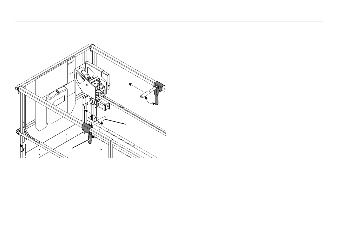
1. Extension Handle in the Stowed
Posi tion
2. Extension Handle in the Extension
Posi tion
5.4 PLATFORM EXTENSION HANDLES
The Platform Extension Handles are mounted to the top
rails of the extension platform at the roller tabs. When
rotated up 90°, the handles provide the operator an
optional grip to push the extension platform out from its
stowed position.
Operation
1. Swing both extension handles up 90° to the extend
position.
2. While standing on the main platform, release the
extension platform lock mechanism with one foot.
3. Grasp both handles and push platform extension out
until locked in either of the two other locked extension positions.
5-8 3121744

5.5 PIPE RACKS
OAD00100
1. Pipe Racks
(Working Position)
2. Capacity Decals
1
1
2
2
OAD00110
3
4
3. Tie-Down Strap 4. Locking Pins
Pipe Racks store pipe or conduit inside the platform in
order to prevent rail damage and optimize platform utility.
The accessory consists of two racks attached to the lower
platform handrail with adjustable straps that secure the
load in place.
SECTION 5 - ACCESSORIES
NOTE: This accessory is available for the 1932R in CE and Austra-
lian markets only.
3121744 5-9

SECTION 5 - ACCESSORIES
Safety Precautions
THIS ACCESSORY AFFECTS OVERALL PLATFORM CAPACITY. REFER TO CAPACITY DECALS AND ADJUST ACCORDINGLY. WEIGHT IN RACKS PLUS WEIGHT IN
PLATFORM MUST NOT EXCEED RATED CAPACITY.
RETRACT PLATFORM EXTENSION BEFORE ATTACHING PIPE RACKS AND LOADING
MATERIAL.
MAXIMUM WEIGHT IN RACKS IS 45 KG (100 LB) EVENLY DISTRIBUTED BETWEEN
RACKS. MAX LENGTH IS 6 M (20 FT). MAX CIRCUMFERENCE OF MATERIAL IS 180 MM
PER PIPE.
• Do not exit platform over rails or stand on rails.
• Do not drive the machine without material secured.
• Use this accessory on approved models only.
• Return racks to the stowed position when not in use.
Preparation and Inspection
• Ensure both racks are mounted and securely
fastened to inside of platform rails.
• Check for missing or damaged components. Replace
if necessary.
Operation
1. To prepare racks for loading, remove locking pins,
rotate each rack 90 degrees from stowed to working
position, then secure with locking pins.
2. Place material onto racks with weight evenly
distributed between both racks. Do not exceed the
rated capacity stated on the decal.
3. Route the tie-down straps at each end across loaded
material and tighten.
4. To remove material, loosen and remove tie-down
straps, then carefully remove material from racks.
NOTE: Reinstall tie-down straps across any remaining material
before continuing machine operations.
5. When not in use, remove locking pins, rotate racks 90
degrees to the stowed position, then secure locking
pins.
5-10 3121744
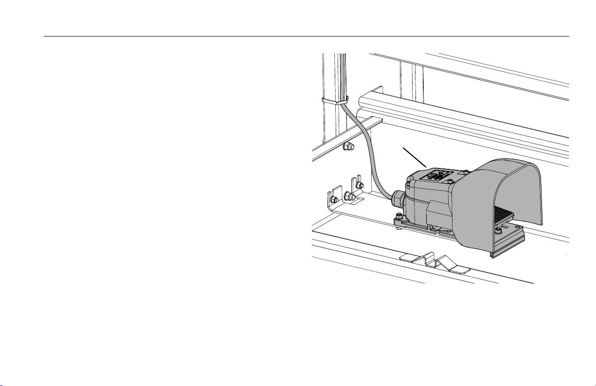
5.6 FOOTSWITCH
OAD00120
1
1.Footswitch Assembly
The Footswitch serves as another enable switch in the
function control circuit. It must be depressed in sequence
with the platform control joystick trigger switch to enable
operation of machine functions when using the platform
controls. Power is removed from the platform controls
when the footswitch is released.
NOTE: This accessory is only available in Japanese and Korean
markets .
Operation
To operate a function, engage the footswitch and joystick
trigger in any sequence before operating a function.
SECTION 5 - ACCESSORIES
3121744 5-11
SECTION 5 - ACCESSORIES
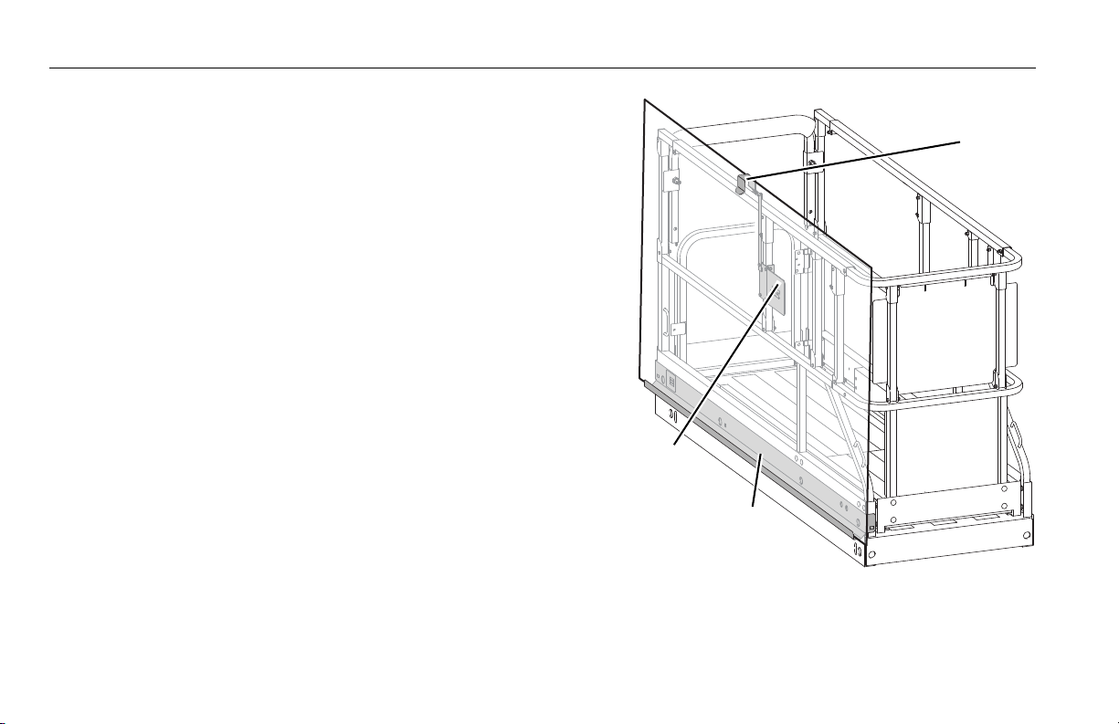
0"%
1
2
3
1. Adjustable Bracket
2. Capacity Decal (on back)
3. Carrier Tray
5.7 PANEL CARRIER
The Panel Carrier can transport flat sheets or panels to an
elevated site by positioning them in a channel on the outside of the platform. It consists of a carrier tray that runs
parallel to the length of the platform and an adjustable
bracket mounted to the handrail to hold material in place.
The panels can measure up to 4 ft x 8 ft (1.22 m x 2.4 m), or
approximately 32 ft sq. (3 m sq.).
This accessory is unavailable for model 1930ES except in
CE and AUS markets.
5-12 3121744

SECTION 5 - ACCESSORIES
Safety Precautions
MULTIPLE MATERIAL-HANDLING ACCESSORIES CAN BE INSTALLED BUT ONLY
ONE MAY BE LOADED AT A TIME UNLESS APPROVED BY JLG INDUSTRIES, INC.
THIS ACCESSORY AFFECTS THE OVERALL PLATFORM CAPACITY. REFER TO THE
CAPACITY DECAL AND ADJUST ACCORDINGLY.
WHEN THE CARRIER TRAY IS LOADED, THE INCREASE OF AREA EXPOSED TO
WIND WILL DECREASE STABILITY. REFER TO THE DECAL FOR MAXIMUM
PANEL SIZE AND WIND SPEED.
• Ensure no personnel are beneath the platform.
• Do not exit the platform over the rails, or stand on
the rails.
• Remove the tray when not in use.
Preparation and Inspection
• Ensure all components are secured to the platform.
• Check for any missing or damaged components.
Replace if necessary.
• Check for loose nuts and bolts. If necessary, torque
according to the Torque Chart specifications in the
Service Manual.
• Replace any missing or illegible decals.
• Replace any torn or frayed straps.
Operation
1. Attach the carrier tray to the outside of the platform.
2. Load the Panel Carrier with material and secure with
the adjustable bracket.
3. Position the panel to its desired location.
4. Remove the carrier tray when finished.
3121744 5-13

SECTION 5 - ACCESSORIES
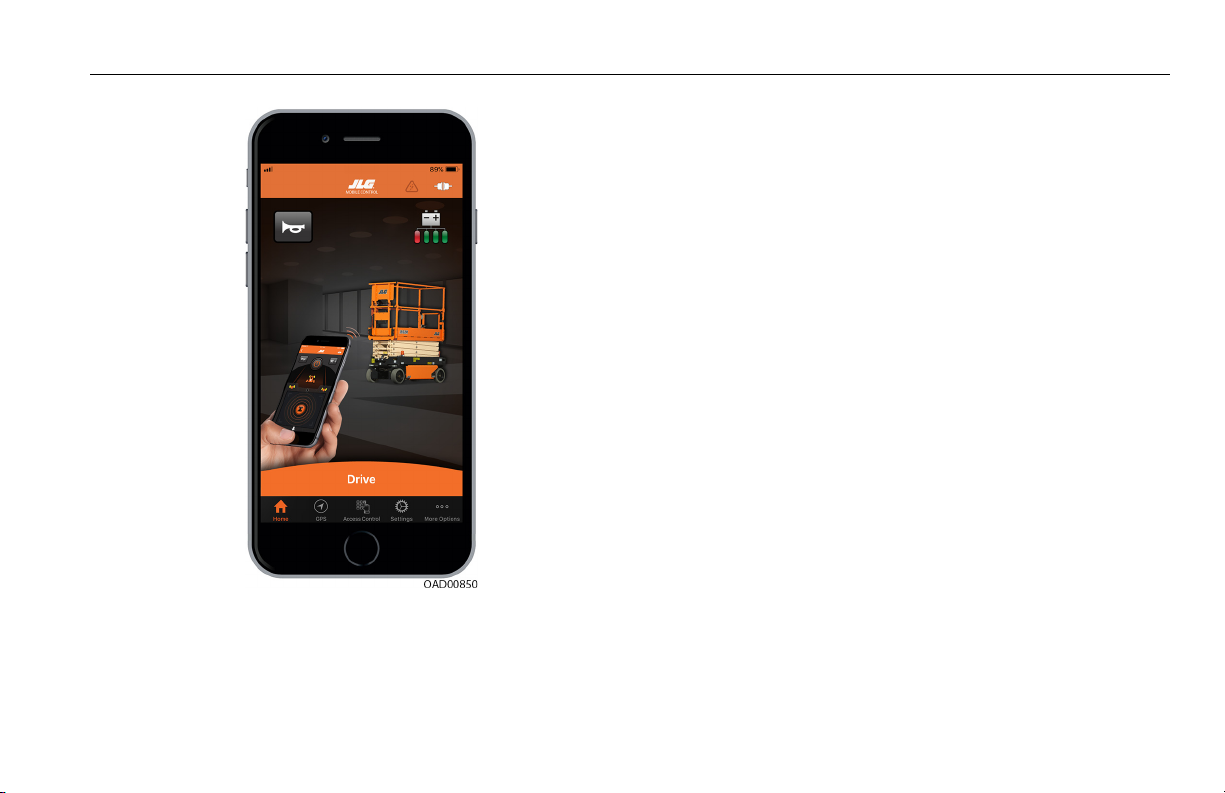
5.8 JLG™ MOBILE CONTROL
The JLG Mobile Control application allows machine
operators to drive remotely from a Bluetooth® equipped
handheld iOS mobile device.
Prior to operation, the machine operator first pairs a
Mobile Control Module equipped machine with a
JLG Mobile Control loaded mobile device by scanning a QR
Code on the machine.
Operation
Download, read, and understand the JLG Mobile Control
Manual from www.JLG.com prior to using the JLG Mobile
Control.
WARNING
NEVER drive the machine using JLG Mobile Control while
standing in the platform, or without clear line-of-sight
between the machine and the destination, as serious
injury could occur to operator or bystander.
Download
Download the JLG Mobile Control on a Bluetooth® equipped
iOS handheld mobile device by visiting
www.JLG.com/mobilecontrol, the Apple Store®
or Google Play®.
5-14 3121744
SECTION 5 - ACCESSORIES
1. JLG Mobile Control
3121744 5-15

SECTION 5 - ACCESSORIES
b
a
c
d
Document Resources
Access to application related documentation.
1. Select Settings (a) from the Home Screen
2. Select either:
b. JLG Mobile Control manual
c. Legal Statements
d. Regulatory Statements
The Bluetooth™ word mark and logos are registered
trademarks owned by Bluetooth SIG, Inc. and any use of
such marks by JLG is under license. Other trademarks and
trade names are those of their respective owners.
5-16 3121744

SECTION 5 - ACCESSORIES
3121744 5-17

SECTION 5 - ACCESSORIES
5-18 3121744
 Loading...