


Ingersoll Rand
System Automation
ir-PCB
Instruction Manual
Before installing or starting this unit for the first time, this manual should be studied carefully to obtain a working knowledge of the unit and or the duties to be performed while operating and maintaining the unit.
RETAIN THIS MANUAL WITH UNIT. This Technical manual contains IMPORTANT SAFETY DATA and should be kept with the unit at all times.
More Than Air. Answers.
Online answers: http://www.air.irco.com
C.C.N. : 80444482 REV. : A
DATE : DECEMBER 2007
Section 1 - TABLE OF CONTENTS
Section 1 - TABLE OF CONTENTS.............................. |
2 |
|
SECTION 2 |
- INTRODUCTION....................................... |
3 |
SECTION 3 |
-safety........................................................ |
3 |
INSTALLATION.............................................................................. |
3 |
|
OPERATION .................................................................................. |
3 |
|
MAINTENANCE AND REPAIR.................................................. |
3 |
|
SECTION 4 |
- COMPRESSOR CONNECTION AND |
|
CONTROL.......................................................................... |
|
5 |
.R-PCB INTERFACE MODULE ................................................... |
5 |
|
Refer to Section Indicated |
|
|
note |
|
|
Important or caution, Safety |
|
|
SECTION 2 - INTRODUCTION
Each air compressor in your system can be interfaced to the X8I using the included IR-PCB interface modules. Any compressor with an available control voltage of 12-250V (either 50Hz or 60Hz) can be controlled by the X8I.
The interface module is mounted inside the compressor’s starter panel and connected to the X8I by using a shielded 7-conductor cable or individual cables run through grounded conduit.
Each air compressor must be equipped with an online/ offline pressure regulation system capable of accepting a remote load/unload signal through a volt-free switching contact or a single electro-mechanical pressure switch.
SECTION 3 -safety
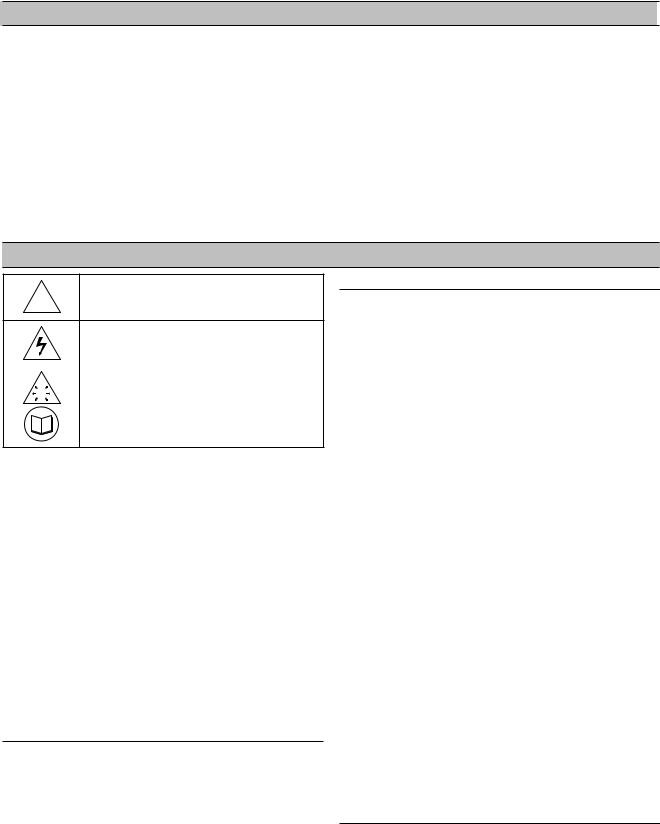
!WARNING : Risk of Danger
|
WARNING : Risk of Electric Shock |
|
|
! |
WARNING : Risk of High Pressure |
|
|
|
|
|
WARNING : Consult Manual |
•Before installing or operating the ir-PCB, take time to carefully read all the instructions
contained in this manual, all compressor manuals, and all manuals of any other peripheral devices that may be installed or connected to the unit.
•Electricity and compressed air have the potential to cause severe personal injury or property damage.
•The operator should use common sense and good working practices while operating and maintaining this system. All applicable codes should be strictly adhered to.
•Maintenance must be performed by adequately qualified personnel that are equipped with the proper tools.
INSTALLATION
•Installation work must only be carried out by a competent person under qualified supervision.
•A fused isolation switch must be fitted between the main power supply and the ir-PCB .
•The ir-PCB should be mounted in such a location as to allow operational and maintenance
access without obstruction or hazard and to allow clear visibility of indicators at all times.
•If raised platforms are required to provide access to the ir-PCB , they must not interfere with
normal operation or obstruct access. Platforms and stairs should be of grid or plate construction with safety rails on all open sides.
OPERATION
The ir-PCB must only be operated by
competent personnel under qualified supervision.
Never remove or tamper with safety devices, guards or insulation materials fitted to the ir-PCB .
The ir-PCB must only be operated at
the supply voltage and frequency for which it is
designed.
When main power is switched on, lethal voltages are present in the electrical circuits and extreme caution must be exercised whenever it is necessary to carry out any work on the unit.
Do not open access panels or touch electrical components while voltage is applied unless it is necessary for measurements, tests or adjustments. Such work should be carried out only by a qualified electrician equipped with the correct tools and wearing appropriate protection against electrical hazards.
All air compressors and/or other equipment connected to the unit should have a warning sign attached stating “THIS UNIT MAY START WITHOUT WARNING” next to the display panel.
If an air compressor and/or other equipment connected to the unit is to be started remotely, attach two warning signs to the equipment stating “THIS UNIT CAN BE STARTED REMOTELY”. Attach one sign in a prominent location on the outside of the equipment, and the other sign inside the equipment control compartment.
MAINTENANCE AND REPAIR
Maintenance, repairs or modifications must only be carried out by competent personnel under qualified supervision.
If replacement parts are required, use only genuine parts from the original equipment manufacturer, or an alternative approved source.
 Loading...