


Ingersoll Rand
System Automation
X12I
Operator’s Manual
Before installing or starting this unit for the first time, this manual should be studied carefully to obtain a working knowledge of the unit and/or the duties to be performed while operating and maintaining the unit.
RETAIN THIS MANUAL WITH UNIT. This Technical manual contains IMPORTANT SAFETY DATA and should be kept with the unit at all times.
More Than Air, Answers.
Online answers: http://www.air.irco.com
C.C.N. : |
80445075 |
REV. |
A |
DATE |
DECEMBER 2008 |

TABLE OF CONTENTS
TABLE OF CONTENTS.................................................. |
2 |
SECTION 1 — INTRODUCTION .................................... |
3 |
SECTION 2 — SAFETY PRECAUTIONS........................... |
3 |
INSTALLATION................................................................. |
3 |
OPERATION.................................................................... |
3 |
SERVICE MAINTENANCE AND REPAIR................................... |
4 |
SECTION 3 — COMPRESSOR CONNECTION AND |
|
CONTROL................................................................... |
5 |
COMPRESSOR CONNECTION .............................................. |
5 |
STANDARD CONNECTION METHODS ................................... |
5 |
OPTIONAL CONNECTION METHODS .................................... |
6 |
PRESSURE DETECTION AND CONTROL................................. |
10 |
X12I MAIN DISPLAY OVERVIEW......................................... |
11 |
X12I SYSTEM OVERVIEW ................................................. |
12 |
X12I INSTALLATION OVERVIEW......................................... |
13 |
SECTION 4 — INSTALLATION .................................... |
14 |
UNIT LOCATION ............................................................ |
14 |
POWER SUPPLY............................................................. |
14 |
PRESSURE SENSOR LOCATION .......................................... |
15 |
PRESSURE SENSOR CONNECTION...................................... |
15 |
IR 485 AND IRV 485 GATEWAY MODULE ......................... |
16 |
IR485 COMMUNICATION PROTOCOL ................................. |
16 |
RS485 NETWORK......................................................... |
16 |
COMPRESSOR INTERFACE IR PCB ..................................... |
18 |
IR PCB EXP BOX (OPTION) ............................................. |
18 |
ON BOARD I/O OPTIONS.................................................. |
19 |
SECTION 5 — CONTROL FEATURES AND FUNCTIONS. 21 |
|
PRESSURE CONTROL ....................................................... |
21 |
ANTI CYCLING CONTROL .......................................... |
21 |
TOLERANCE .............................................................. |
22 |
DAMPING ................................................................. |
22 |
SYSTEM VOLUME...................................................... |
23 |
SEQUENCE CONTROL STRATEGIES ..................................... |
24 |
STANDARD CONTROL FEATURES AND FUNCTIONALITY .......... |
24 |
ALTERNATE CONTROL STRATEGIES ..................................... |
28 |
ADDITIONAL CONTROL FEATURES AND FUNCTIONALITY .......... |
29 |
SECTION 6 — DISPLAY AND MENU OPERATION ........ |
31 |
USER MENU ................................................................. |
33 |
INFORMATION DISPLAYS ................................................. |
34 |
INDICATOR LED’S.......................................................... |
36 |
COMPRESSOR IDENTIFICATION ......................................... |
37 |
X12I CONTROL KEYPAD FUNCTIONS ................................. |
37 |
SECTION 7 — COMMISSIONING................................ |
39 |
PHYSICAL CHECKS.......................................................... |
39 |
PRESSURE DISPLAY ........................................................ |
39 |
X12I QUICK SET UP CONFIGURATION ............................... |
39 |
OPTIONAL FEATURES AND FUNCTIONS ............................... |
39 |
SECTION 8 — SYSTEM CONFIGURATION................... |
40 |
DISPLAY ITEM STRUCTURE ................................................ |
40 |
ACCESSING THE X12I CONFIGURATION SCREENS.................... |
40 |
USER LEVEL MENUS ....................................................... |
42 |
SERVICE LEVEL MENUS (0021) ........................................ |
43 |
HIGH LEVEL MENUS (0032) ............................................ |
44 |
X12I CONFIGURATION SCREENS......................................... |
45 |
X12I COMPRESSOR CONNECTIVITY AND FUNCTIONAL SETTINGS |
|
.................................................................................. |
56 |
SECTION 9 VIRTUAL RELAY AUTOMATION.............. |
59 |
VIRTUAL RELAY CONFIGURATION ...................................... |
62 |
FUNCTION LISTS............................................................. |
67 |
VIRTUAL RELAY AUTOMATION EXAMPLES ........................... |
71 |
SECTION 10 — DIAGNOSTICS.................................... |
73 |
SECTION 11 — X12I FAULT INDICATIONS.................. |
77 |
ERROR LOG................................................................... |
77 |
FAULT CODES................................................................. |
78 |
INTERNAL CONTROLLER FAULT ‘E’ CODES............................. |
79 |
SECTION 12 — PARTS LIST........................................ |
80 |
SECTION 13 — TECHNICAL DATA .............................. |
80 |
SECTION 14 — WIRING DIAGRAM ............................ |
81 |
X12I SCHEMATIC........................................................... |
81 |
X12I XPM AI4 & XPM DI8R4 ...................................... |
82 |
X12I TERMINAL PCB ..................................................... |
83 |
XPM TAC24 ............................................................... |
84 |
SECTION 15 — COMMISSIONING FORM ................... |
85 |
NOTES ..................................................................... |
91 |
Refer to Section Indicated
Note
Important or Caution, Safety
2
SECTION 1 — INTRODUCTION
The X12I is an advanced system controller designed to provide safe, reliable, and energy-efficient management of your compressed air system. The X12I is capable of controlling up to twelve (12) positive displacement air compressors. The compressors may be fixed speed, variable speed or multi-step and have electro-pneumatic or microprocessor based controls.
The X12I is uniquely configurable and customizable to meet the specific needs of some of the most complex compressed air system. Additionally, the X12I control network can expand to include monitoring and control of various compressed air system components.
SECTION 2 — SAFETY PRECAUTIONS
ALWAYS EMPLOY SAFE WORKING PRACTISE AND PROCEDURES
WARNING: Risk of Danger
WARNING: Risk of Electric Shock
WARNING: Risk of High Pressure
WARNING: Consult Manual
Before installing or operating the product, take time to carefully read all the instructions contained in this manual, all compressor manuals, and all manuals of any other peripheral devices that may be installed or connected to the unit.
When installing, commissioning, operating or carrying out service or maintenance on a product, personnel must use safe working practice and observe all relevant local health and safety requirements and regulations.
Electricity and compressed air have the potential to cause severe personal injury or property damage
Lethal voltages are used within the product. Use extreme caution when carrying out electrical checks. Isolate the power supply before starting any maintenance work.
Maintenance must be performed by adequately qualified personnel that are equipped with the proper tools. If the user employs an operating procedure, an item of equipment, or a method of working which is not specifically recommended, the user must ensure the product will not be damaged or made unsafe and that there is no risk to persons or property.
It is not possible to anticipate every circumstance that might represent a potential hazard. Failure to observe safety precautions or implement safe working practices may be considered dangerous practice or misuse of the product.
INSTALLATION
Installation work must only be carried out by a competent person under qualified supervision.
A fused isolation switch must be fitted between the main power supply and the product.
The product should be mounted in such a location as to allow operational and maintenance access without obstruction or hazard and to allow clear visibility of indicators at all times.
If raised platforms are required to provide access to the product they must not interfere with normal operation or obstruct access. Platforms and stairs should be of grid or plate construction with safety rails on all open sides.
OPERATION
The product must only be operated by competent personnel under qualified supervision.
Never remove or tamper with safety devices, guards or insulation materials fitted to the unit.
The product must only be operated at the supply voltage and frequency for which it is designed.
When mains power is switched on, lethal voltages are present in the electrical circuits and extreme caution must be exercised whenever it is necessary to carry out any work on the unit.
Do not open access panels or touch electrical components while voltage is applied unless it is necessary for measurements, tests or adjustments. This work must only be carried out by a qualified electrician or technician equipped with the correct tools and appropriate protection against electrical hazards.
All air compressors and/or other machine equipment connected too, and controlled by, the product should have a warning sign attached stating ‘THIS UNIT MAY START WITHOUT WARNING' next to the display panel.
If an air compressor and/or other machine equipment connected too, and controlled by, the product is to be started remotely, attach warning signs to the machine stating ‘THIS UNIT CAN BE STARTED REMOTELY’ in a prominent location, one on the outside of the machine, the other inside the machine control compartment.
3

SERVICE MAINTENANCE AND REPAIR
Service, maintenance, repairs or modifications must only be carried out by competent personnel under qualified supervision.
If replacement parts are required use only genuine parts from the original equipment manufacturer, or an alternative approved source.
Carry out the following operations before opening or removing any access panels or carrying out any work on the product:-
•Isolate from the main electrical power supply. Lock the isolator in the 'OFF' position and remove the fuses.
•Attach a label to the isolator switch and to the product stating ‘WORK IN PROGRESS - DO NOT APPLY VOLTAGE'. Do not switch on electrical power or attempt to start the unit if such a warning label is attached.
Ensure that all instructions concerning operation and maintenance are strictly followed and that the complete product, with all accessories and safety devices, is kept in good working order.
The accuracy of sensor devices must be checked on a regular basis. They must be renewed when acceptable tolerances are exceeded. Always ensure any pressure within a compressed air system is safely vented to atmosphere before attempting to remove or install a sensor device.
The product must only be cleaned with a damp cloth, using mild detergents if necessary. Avoid the use of any substances containing corrosive acids or alkalis.
Do not paint the control facial or obscure any indications, controls, instructions or warnings.
4
SECTION 3 — COMPRESSOR CONNECTION AND CONTROL
COMPRESSOR CONNECTION
Each air compressor in your system must be interfaced to the X12I. Interface methods may vary depending on the compressor type and/or local control configuration. The following are main methods for interfacing compressors to the X12I:
1)The ir-PCB Interface
2)The ir-485 Gateway Interface
3)The irV-485 Gateway Interface
4)Direct Connect via RS485
5)Special Application Interface
 Consult the air compressor manual or your air compressor supplier/specialist for details before installing the X12I.
 Consult the X12I Interconnect and Application
Guide
STANDARD CONNECTION METHODS
1) The ir-PCB Interface module that is designed to interface to any positive displacement air compressor (regardless of make or manufacturer) with an available control voltage of 12-250V (either 50Hz or 60Hz).
The ir-PCB interface module is installed within the compressor control area and connected to the X12I using a six (6) wire cable, (seven (7)-wire cable for Nirvana 7.5 to 15HP (5.5 to 11KW).
Each air compressor must be equipped with an online/offline pressure regulation system capable of accepting a remote load/unload signal through a volt-free switching contact or a single electro-mechanical pressure switch.
 ir-PCB Manual
2) The ir-485 Gateway Interface module that is designed to interface to any Ingersoll Rand Intellisys controlled (Non-Nirvana) compressor. The X12I communicates to the ir-485 Gateway via a two wire, RS485 network utilizing the ir485 protocol. All IR compressors equipped with Intellisys controllers (NonNirvana and Recips) require this interface.
 All Nirvana Compressors, 20 HP (15KW) and above require the irV-485 Gateway.
The ir-485 Gateway interface module is installed within the compressor control cabinet and connected to the X12I using Belden 9841 or equivalent RS485 cable.
 ir-485 & irV485 Manual
3) The irV-485 Gateway Interface module that is designed to interface to any Ingersoll Rand Nirvana compressor. The X12I communicates to the irV-485 Gateway via a two wire, RS485 network utilizing the ir485 protocol. All Nirvana Compressors, 20 HP (15KW) and above, and Recips, with Redeye and SG controllers, require this interface.
The irV-485 Gateway interface module is installed within the compressor control cabinet and connected to the X12I using Belden 9841 or equivalent RS485 cable.
 Nirvana 7.5 to 15HP (5.5 to 11KW) connect via the ir-PCB using seven (7)-wire cable.
 ir-485 & irV485 Manual
4) Direct Connect via RS485 to any Ingersoll Rand compressor (R-Series) that has an integrated RS485 network port utilizing the ir485 protocol. The X12I communicates to these compressors via a two wire, RS485 network. The compressor is connected to the X12I using Belden 9841 or equivalent RS485 cable.
 R-Series Manual
5
OPTIONAL CONNECTION METHODS
5) Special Application Interface uses integration boxes designed to accommodate various types of compressor and regulation methods and system monitoring.
Expansion Module: EXP Box (Option)
As standard the X12I has four direct connect ‘ir-PCB’ terminal connections. This capability can be extended with the use of tw0 (2) optional EXP Boxes. Each EXP Box will add another four direct connect ‘ir-PCB’ connection terminals. This would allow a total of 12 compressors to connected and controlled via ‘ir-PCB’ integration.
Compressors 1-4 connect via the X12I Compressors 5-8 connect via EXP Box #1 Compressors 9-12 connect via EXP Box #2
The EXP Box is suitable for wall mounting and must be located adjacent to the X12I unit (max 33ft or 10m).
The EXP Box connects to the X12I controller via a two wire, dedicated RS485 network
 Use Belden 9841 or Equivalent In Grounded Conduit No Greater Than 33ft (10m)
Up to four air compressors can be connected to the EXP Box using a 6 or 7 wire cable and a compressor interface ir-PCB (330ft (100m) max). The ‘ir-PCB’ connections are identical to the X12I.
 EXP Box Manual
Remote Compressor Management; EX Box (option)
The EX Box is an ‘EXtension’ to the X12I providing additional ‘ir-PCB’ connectivity.
The EX Box will typically be used to provide ‘ir-PCB’ connectivity at a remote location beyond the maximum distance specification of compressors that require ‘irPCB’ type connection; 330ft (100m). This effectively expands the hardwire connection scheme of the ‘ir-PCB” to the full RS485 distance specification.
The EX box is suitable for wall mounting and can be located up to 4000ft (1219m) from the X12I unit.
The EX Box connects to the X12I controller via a two wire, RS485 network utilizing the ir485 protocol
 Use Belden 9841 or Equivalent In Grounded Conduit No Greater Than 4000ft (1219m)
One (1) or two (2) air compressors can be connected to the EX Box using a 6-wire cable and a compressor interface ir-PCB (330ft (100m) max). The ‘ir-PCB’ connections are identical to the X12I.
The EX Box also provides optional ‘local pressure sensor’ connections. The compressor delivery pressure, local system pressure and air treatment differential pressure can be displayed.
Multiple EX Boxes can be connected to the X12I as long as the number of compressors does not exceed the maximum number of compressors (12).
 EX Box Manual
6

Bolt-On VSD Control Integration: VSD Box (option)
The VSD Box is intended to provide a method of system integration for a VSD (Variable Speed Drive) air compressor that is not equipped with any accessible means of remote connectivity (such as IRNirvana). The VSD Box will provide required functionality to enable system integration and efficient control using the X12I automation system.
The VSD Box connects to the X12I controller via a two wire, RS485 network utilizing the ir485 protocol
 Use Belden 9841 or Equivalent In Grounded Conduit No Greater Than 4000ft (1219m)
Each air compressor in a system, that requires VSD Box integration, must be equipped with an individual VSD Box. Multiple VSD Boxes can be connected to the X12I as long as the number of compressors does not exceed the maximum number of compressors (12).
 VSD Box Manual
Remote Compressor Management; CX Box (option)
The CX Box is intended to provide a method of system integration for non-Ingersoll Rand air compressors that are not equipped with any accessible means of remote connectivity.
The CX Box provides advanced monitoring and control functionality for the following compressor types:
•Load/Unload
•3-Step
•5-Step
•Poppet Valve
•Modulation Valve
•Spiral Valve
•Variable Speed Inverter Drive
The CX Box connects to the X12I controller via a two wire, RS485 network utilizing the ir485 protocol
 Use Belden 9841 or Equivalent In Grounded Conduit No Greater Than 4000ft (1219m)
Each air compressor in a system that requires CX Box integration must be equipped with an individual CX Box. Multiple CX Boxes can be connected to the X12I as long as the number of compressors does not exceed the maximum number of compressors (12).
 CX Box Manual
7
Remote Compressor Management; DX Box (option)
The DX Box is designed to allow two fixed speed online/offline air compressors to be seen as one compressor by the X12I.
This functionality provides the ability to:
a)Group two adjacent air compressors together as a single coherent unit.
b)Combine two similar capacity compressors together to form a three-step variable output group acting as a single coherent variable output unit.
c)Take advantage of a small or minimal capacity compressor, grouped together with a medium or higher capacity compressor, to form a high
capacity, variable output, group acting as a single variable output ‘top-up’ compressor.
The DX Box also provides optional local pressure sensor connections. The compressor discharge pressures, local system pressure and air treatment differential pressures can be displayed. The monitored local pressure is available on the system network and can be utilized by the X12I for advanced pressure related functions.
The DX Box connects to the X12I controller via a two wire, RS485 network utilizing the ir485 protocol
 Use Belden 9841 or Equivalent In Grounded Conduit No Greater Than 4000ft (1219m)
The DX Box provides for two ‘ir-PCB’ connections. The DX Box can also be used to provide ‘ir-PCB’ connectivity at a remote location beyond the maximum distance specification of direct X12I connection.
Multiple DX Boxes can be connected to the X12I as long as the number of compressors does not exceed the maximum number of compressors (12).
 DX Box Manual
Remote Input & Output: I/O Box (option)
An I/O Box provides additional general purpose I/O (input/output) for a system enhancing monitoring capabilities and providing distributed system automation.
Up to twelve I/O Boxes can be connected to the X12I controller. Each I/O Box features:
•8 Digital Inputs
•5 Analog Inputs
•6 Relay Outputs
The I/O Box connects to the X12I controller via a two wire, RS485 network utilizing the ir485 protocol
 Use Belden 9841 or Equivalent In Grounded Conduit No Greater Than 4000ft (1219m)
Digital inputs can be used to monitor switching contact devices. Each input can be set to act as an Alarm or High Level Alarm input. Digital inputs can also be used for metering (for example m3, ft3, kWh) providing an accumulative count of pulses from a metering device.
Analog inputs can be used to monitor sensor devices (for example: pressure differential, temperature, dewpoint, flow, current, power, and bearing condition). Each input is equipped with adjustable high or low level detection that can be used to activate an Alarm or High Level Alarm.
Relay outputs use ‘Virtual Relay Automation’ technology and are totally configurable with duel input logic functions. Relay functions can be assigned utilizing any status or condition information available on a system network from any compatible unit connected to the network.
 I/O Box Manual
8
Visualization: VX Box (Option)
The VX Box provides “visualization” of the X12I Automation System. The VX Box incorporates hardware and software to allow monitoring of the X12I Automation system and equipment in a simple format. To access the application running in the VX Box, simply connect via a Web Browser from any PC using an Ethernet connection. The PC can be local “stand alone” or part of a LAN.
Once logged into the VX Box, the following items are available to the user:
System status & control
System performance reporting
Equipment status monitoring
Equipment maintenance scheduler
Graphing & Trending tools
Reporting tools
Warning & Alarm monitoring
SMS messaging
Email messaging
The VX Box is fully field configurable using standard screen templates.
The VX Box connects to the X12I controller via a two wire, RS485 network utilizing the ir485 protocol
 Use Belden 9841 or Equivalent In Grounded Conduit No Greater Than 4000ft (1219m)
The VX Box connects to the customer’s PC or LAN via Ethernet, using a RJ45 connector, Cat5e 10/100BaseT cable.
 VX Box Manual
System Modbus Gateway: SMG Box (Option)
The SMG Box is designed to provide a RS485 Modbus connection to the X12I Automation System. This allows a customer’s computer, PLC, or DCS to connect to, monitor, and control the X12I Automation System from a remote location.
The SMG Box connects to the X12I controller via a two wire, RS485 network utilizing the ir485 protocol
 Use Belden 9841 or Equivalent In Grounded Conduit No Greater Than 4000ft (1219m)
The SMG Box communicates to the customer’s computer, PLC, DCS via a two wire, RS485 network utilizing the Modbus protocol.
 Use Belden 9841 or Equivalent In Grounded Conduit No Greater Than 4000ft (1219m)
Ethernet to RS485 Converter:
Lantronix XSDRIN-02 Xpress-DR-IAP or equivalent
Serial to RS485 Converter:
B&B Electronics 4WSD9OTB or equivient
 SMG Box Manual
9
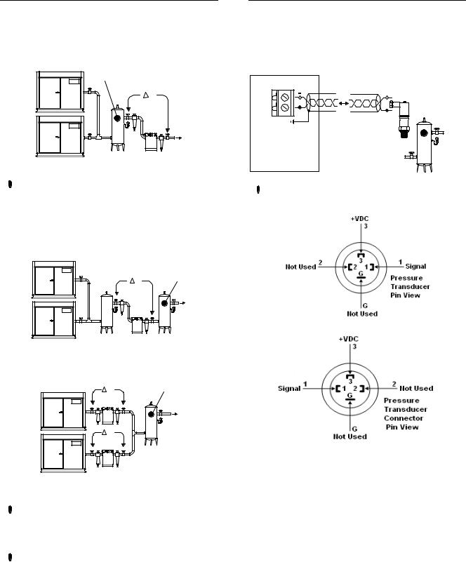
PRESSURE DETECTION AND CONTROL
The X12I utilizes the signal from an electronic pressure sensor that can be mounted remotely from the X12I in a suitable location in the compressed air system.
The default setup of the X12I is for operation with a 232psi (16bar) 4-20ma pressure sensor. The X12I can accept an input from any 4-20mA type pressure sensor with a range from 14.5psi (1bar) up to 8700psi (600bar).
 Consult the Pressure Sensor Calibration Procedure for information regarding the use and setup of the pressure sensor.
 Pressure Sensor Calibration Procedure
10
X12I MAIN DISPLAY OVERVIEW
|
|
a |
b |
|
|
102 |
PSI |
|
|
c |
|
d |
1 |
|
|
e |
|
17:30 |
#1 |
|
|
a
b  CAP
CAP 
c
a 

 b
b 


 c
c  1
1
a |
b |
c |
|
g |
|
f |
|
d |
|
h |
e |
11

X12I SYSTEM OVERVIEW
12
X12I INSTALLATION OVERVIEW
Dimensions |
SPECIFICATIONS |
13.4” x 9.45” x 6.0” |
|
Weight |
340mm x 241mm x 152mm |
16.5lb (7.5kg) |
|
Mounting |
Wall, 4 x screw fixings |
Enclosure |
IP54, NEMA 12 |
Supply |
230Vac +/- 10%, 50 Hz |
Power |
115Vac +/- 10%, 60 Hz |
100VA |
|
Temperature 32°F to 115°F |
|
Humidity |
(0°C to 46°C) |
0% to 95% RH |
|
|
(non-condensing) |
Local Disconnect (Breaker) Box
Fused for 100VA On/Off Switch
Power Cable
3 conductor (N, L, E) (Sized in accordance with local electrical and safety regulations).
PRESSURE TRANSDUCER CABLE
2 Conductor Cable, 20 Gauge Stranded
Earth Shielded
No Greater Than 330FT (100M)
24VDC Control Voltage
X12I X05 CONNECTOR |
PT CONNECTOR |
25 |
+VDC Pin #3 |
26 |
Signal Pin #1 |
Reference X12I Operations Manual for Pressure Sensor Connection Details
PRESSURE TRANSDUCER
To Plant Air
System
RECEIVER
Ingersoll Rand Automation
Model X12I
|
EXP RS485 Network Cable |
|
Supply |
|
|
Voltage |
EXP RS485 NETWORK CABLE |
|
Cable |
||
Belden 9841 or Equivalent |
||
|
||
|
In Grounded Conduit |
|
|
No Greater Than 33FT (10) |
|
Pressure Transducer |
RS485 Network Cable |
|
Cable |
||
|
|
RS485 NETWORK CABLE |
|
|
Belden 9841 or Equivalent |
|
|
In Grounded Conduit |
|
|
No Greater Than 4000FT (1219M) |
|
ir-PCB |
ir-PCB COMPRESSOR CONTROL CABLE |
|
|
||
|
7 Conductor Cable, 18 Gauge, Stranded, Earth Shielded |
|
|
OR |
|
|
Single Conductor Wire, 20 Gauge Stranded, Quantity (7) In |
|
|
Grounded Conduit No Greater Than 330FT (100M) |
|
|
24VAC Control Voltage |
|
ir-PCB Compressor Control Cable |
|
|
|
Reference X12I Application and Interconnect Guide For |
|
PRESSURE TRANSDUCER THREADS |
Wiring Connections Between The X12I, The ir-PCB, and The |
|
Compressor |
||
BPT G1/4” DIN3852, |
||
|
||
Form E, Inox 1, 4305 STainless |
|
|
Equivalent of ¼” NPT. |
|
DRIP LEG |
|
|
|
|
|
|
|
|
|||
|
|
|
|
||
From Air |
Reference X12I Application and Interconnect Guide For |
The RS485 Network is a Serial, Point to Point |
|||
Compressors |
Wiring Connections Between The X12I, The ir-485 or irV- |
||||
|
|
|
|
485 Gateway and The Compressor, S3 Direct Connects, and |
Communication Network Refer to the X12I Application and |
|
|
|
|
Interconnect Guide For Wiring Details and Connectivity. |
|
|
|
|
|
Optional Special Application Interface Boxes |
|
|
|
|
|
|
|
Ingersoll |
Rand |
From VSD Pressure
Transducer
|
|
|
To VSD Pressure |
|
|
|
|
ir-PCB |
|||
|
|
|
Transducer Input |
ir-485 |
irV-485 |
13
SECTION 4 — INSTALLATION
 It is recommended that installation and commissioning be carried out by an authorized and trained product supplier.
UNIT LOCATION
The X12I can be mounted on a wall using conventional bolts. The X12I can be located remotely from the compressors as long as it is within 330 feet (100 meters) of cable length when connecting compressors directly with an ir-PCB. When connecting the X12I over the RS485 communication network the distance is up to 4000 feet (1219 meters) The X12I must be located within 330 feet (100 meters) of the system pressure transducer.
POWER SUPPLY
A fused switching isolator must be installed to the main incoming power supply, external to the X12I. The isolator must be fitted with a fuse of the correct rating to provide adequate protection to the power supply cable used (in accordance with local electrical and safety regulations).
XPM-TAC24
1 |
2 |
3 |
4 |
X04 |
|
|
|
VOLTAGE SELECT |
|||
230Vac
1 |
2 |
3 |
4 |
X04 |
|
|
|
VOLTAGE SELECT |
|||
115Vac
 Ensure that the voltage select input is properly jumpered for the incoming power. Default voltage configuration is 230Vac.
If it is necessary to adjust the link wires access to the link terminals can be achieved by temporarily removing the DC Power supply unit (DC) located on the main DIN Rail.
B 
DC
 A
A
C
A)Push the DIN Rail mount button located at the bottom of the DC Power supply unit. This action can be achieved by hand; no tooling is required.
B)Remove the DC power supply unit from the DIN Rail and carefully maneuver to the left. There is no need to disconnect any wiring.
C)Click the DC power supply unit back in place when voltage select link adjustment is complete.
 The DC power supply unit is mounted in an inverted orientation on the DIN Rail; this is an intentional design feature.
Connect the incoming power supply wires to the power supply terminal blocks located on the main DIN Rail.
14
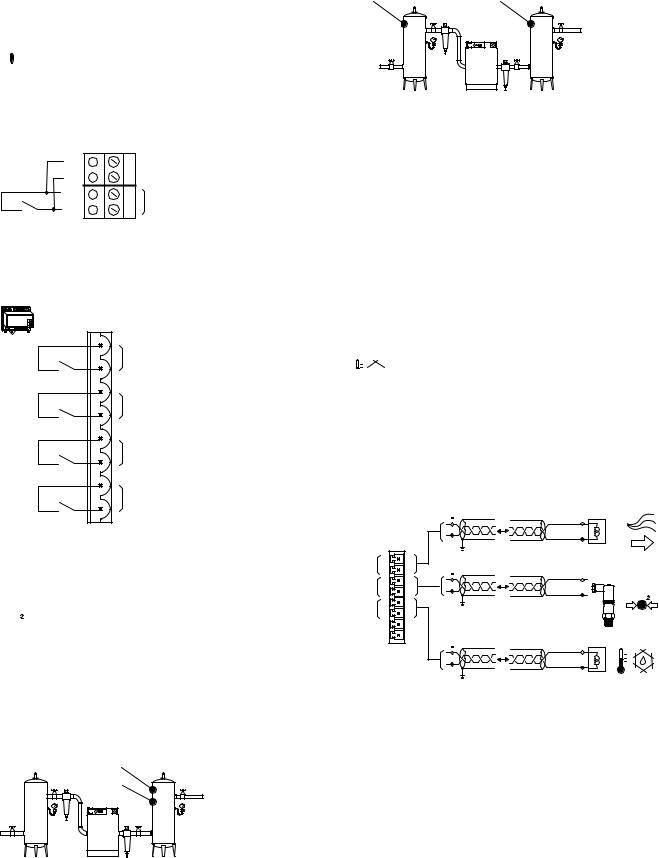
PRESSURE SENSOR LOCATION
The system pressure sensor (P) must be located where it will see the air pressure that is common to all of the compressors.
SUPPLY (WET) Side Pressure Control
|
P |
1 |
P |
|
2 |
Pressure Sensor Located Before Cleanup Equipment
 Dry side pressure will be lower than the system pressure due to pressure differential losses across air treatment equipment. The nominal system pressure will reduce as the air treatment differential pressure increases.
DEMAND (DRY) Side Pressure Control
1 |
P |
P |
|
|
2 |
Pressure Sensor Located After Shared Cleanup
Equipment
P |
P |
1 |
|
P |
|
2 |
|
Pressure Sensor Located After Individual Cleanup
Equipment
 Ensure each compressor is equipped with independent excess pressure shutdown. An increase in pressure differential across air treatment equipment can result in excess compressor discharge pressure.
 Regular routine monitoring of pressure differential across air treatment equipment is recommended.
PRESSURE SENSOR CONNECTION
The pressure sensor must be connected to terminal X05 of the X12I Terminal PCB using a shielded (earth screened), two-conductor (2 core), 20 gauge (0.5mm2 CSA minimum), cable no greater than 330ft (100m) in length.
X05
26 |
|
- |
|
|
|
25 |
+ |
+ |
|
||
|
|
4-20mA |
 Wire polarity is important.
Pressure Sensor Wiring and Location
The pressure transducer threads are BPT G1/4” DIN3852, Form E, Inox 1, 4305 stainless. It is the equivalent of ¼” NPT.
15
IR-485 AND IRV-485 GATEWAY MODULE
The ir-485 and irV-485 Gateways are designed to interface the Intellisys Controller on the Ingersoll Rand Compressors and the Nirvana compressors, 20 HP (15KW) and above, with the X12I via the RS485 Network utilizing the ir485 protocol. The ir-485 and irV-485 Gateways are DIN Rail mounted and can be located within the compressor control gear enclosure or remotely within a separately enclosure.
irV485 |
ir-485 Gateway |
irV-485 Gateway |
The cable used between the X12I and the ir-485 and irV485 Gateways is Belden 9841 (or equivalent). It should be run in grounded conduit and should not be greater than 4000 feet (1219 meters) in length.
The cable used between the ir-485 Gateway and irV-485 Gateways and the Intellisys Controller is included with the Installation Kit
 Consult the X12I Interconnect and Application Guide and the ir-485 or irV-485 Gateway Manual prior to the installation of the X12I and the Compressor Gateway to the air compressor.
IR485 COMMUNICATION PROTOCOL
ir485 is a unique communication protocol designed specifically for Compressor and Air System control. ir485 is a Multi-Master vs. a Master–Slave protocol that enables faster, more effective control of network components. ir485 also features distributed control capabilities and has inherent resistance to communication faults due to noise
 Follow RS485 Network installation recommendations
RS485 NETWORK
The X12I is equipped with an RS485 network communications capability using the ir485 protocol. This facility can be used for remote connectivity to optional networked units and modules with ir485 communications capabilities or compressor controllers equipped with the ir485 capability.
|
X06 |
|
L2 |
30 |
L2 |
L1 |
29 |
L1 |
|
28 |
RS485 |
|
27 |
|
 The RS485 Network is a Serial, Point to Point Communication Network. Refer to the X12I Application and Interconnect Guide For Wiring Details and Connectivity.
The following example details the “correct” method of wiring the RS485 Network
Correct RS485 Network Example
The following example details the “incorrect” method of wiring the RS485 Network
ir-485 |
Incorrect RS485 Network Example
16

RS485 Installation Considerations

 RS485 data communications and other low voltage signals can be subject to electrical interference. This potential can result in intermittent malfunction or anomaly that is difficult to diagnose. To avoid this possibility always use earth shielded cables, securely bonded to a known good earth at one end. In addition, give careful consideration to cable routing during installation.
a)Never route an RS485 data communications or low voltage signal cable alongside a high voltage or 3-phase power supply cable. If it is necessary to cross the path of a power supply cable(s), always cross at a right angle.
b)If it is necessary to follow the route of power supply cables for a short distance (for example: from a compressor X12I to a wall along a suspended cable tray) attach the RS485 or signal cable on the outside of an earthed cable tray such that the cable tray forms an earthed electrical interference shield.
c)Where possible, never route an RS485 or signal cable near to equipment or devices that may be a source of electrical interference (for example: 3-phase power supply transformer, high voltage switchgear unit, frequency inverter drive module, radio communications antenna).
17

COMPRESSOR INTERFACE IR-PCB
The ‘ir-PCB’ is designed to interface a compressor with the X12I using a 6-core (or 7-core for IRV-PCB operation), earth shielded, cable no greater than 330ft (100 meters) in length.
Each compressor in the system must be assigned a unique identification number from 1 up to the number of compressors in the system. The identification number should be clearly indicated on each compressor for operational reference.
For each compressor connected to the X12I utilizing an ‘ir-PCB,’ the signal wires must be connected to the X12I terminals dedicated for the assigned compressor reference number.
C01 |
|
C02 |
|
C04 |
|||
|
i-PCB |
|
#1 |
||||
|
|
C03 |
|
|
|
C05 |
|
V |
1 |
2 |
3 |
4 |
5 |
6 |
|
|
|
|
|
|
|
|
LED 1 LED 2 |
V |
|
|
|
|
|
|
|
|
|
|
|
|
|
|
X01 |
V1 |
1 |
2 |
3 |
4 |
5 |
6 |
|
The ‘ir-PCB’ is a DIN rail mountable module designed to be installed within the compressor control or switchgear area.
Each air compressor must be equipped with a load/unload regulation system and, if not regulated with a single electro-mechanical pressure switch, have a facility for a remote load/unload control with the ability to accept a volt-free switching contact input for remote load/unload.
V For variable speed compressor(s) equipped with a ‘variable/fixed’ digital input function; Install a 7-core cable from the ‘ir-PCB’ to the X12I.
 Consult the air compressor manual or your air compressor supplier/specialist for details before installing the X12I.
 Consult the X-Series Interconnect and Application Guide prior to the installation of the X12I and the ir-PCB to the air compressor.
 Consult the ir-PCB Instruction Manual for information regarding the use of the ir-PCB.
 ir-PCB Instruction Manual
IR-PCB EXP BOX (OPTION)
As standard the X12I has four direct connect ‘ir-PCB’ terminal connections. This capability can be extended with the use of optional ir-PCB EXP Box(s). Each box adds another four direct connect ‘ir-PCB’ terminals. Up to two ir-PCB EXP Boxes can be connected to the X12I to provide a maximum of 12 direct connect ‘ir-PCB’ terminals.
The ir-PCB EXP Box is wall mounting and must be located adjacent to the X12I unit. The distance between the X12I and the ir-PCB EXP Box is no greater than 33ft (10m).
C: 5 - 8
 Consult the air compressor manual or your air compressor supplier/specialist for details before installing the X12I.
 Consult the X12I Interconnect and Application Guide prior to the installation of the X12I and the ir-PCB to the air compressor.
 Consult the EXP Box Instruction Manual for information regarding the use of the EXP Box.
 EXP Box Instruction Manual
18

ON BOARD I/O OPTIONS
DIGITAL INPUTS (OPTIONS)
The X12I is equipped with ten auxiliary inputs.
 Each input is designed to detect a remote ‘volt-free’ switching contact (rated for a minimum 24VDC @ 10mA) with a cable length of 330ft (100m) maximum.
Di1: Digital Input 1, Menu Configurable
X07
32 |
Di1 |
|
31 |
||
|
 Menu Items – S02:D1
The functions of Di2 to Di10 are fixed.
Di2: |
Force Sequence Change |
Di3: |
Remote Start/Stop |
Di4: |
Standby Override |
Di5: |
Table 1 Override |
Di6: |
Table 2 Override |
Di7: |
Table 3 Override |
Di8: |
Table 4 Override |
Di9: |
Table 5 Override |
Di10: |
Table 6 Override |
 XPM-Ai4
 X03
X03
0VDC |
7 |
Di2 |
|
Ai4 |
8 |
||
|
|
|
XPM-Di8R4 |
|
|
|
X03 |
|
Di1 |
1 |
Di3 |
|
2 |
|||
|
|
||
Di2 |
3 |
Di4 |
|
4 |
|||
|
|
||
Di3 |
5 |
Di5 |
|
6 |
|||
|
|||
|
|
||
Di4 |
7 |
Di6 |
|
8 |
|||
|
|
||
Di5 |
9 |
Di7 |
|
10 |
|||
|
|||
|
|
||
Di6 |
11 |
Di8 |
|
|
12 |
||
|
|
||
Di7 |
13 |
Di9 |
|
|
14 |
||
|
|
||
Di8 |
15 |
Di10 |
|
|
16 |
Di2: Force Sequence Change
Initiates an immediate change/review of the compressor sequence assignment. The input must be activated for a minimum of two second. Routine scheduled sequence change events are not disrupted and will still occur as normal.
Di3: Remote Start/Stop
A start command is generated when the input changes state from open to closed. The input must remain closed while running. A stop command is generated when the input changes state from closed to open.
 Local and Communications Start and Stop remain active. If the Stop button is pressed while this input is held closed, the unit will stop.
Di4: Standby Override
All compressors are unloaded and continuously held offloaded. Any active ‘Table’ override input has priority over the standby override input.
Di5 to Di10: Table 1 to 6 Override
The X12I will select the applicable ‘Table’ when a table input is activated. The X12I will return to normal table selection, in accordance with pressure schedule or menu setting, when no table input is activated.
 When a table override input is activated the display will show a manual table override symbol adjacent to the ‘table’ symbol.
If more than one table override input is activated at the same time the X12I will give priority to the lowest table number. For example: If table 2 and 3 override inputs are activated at the same time the X12I will use table 2.
19
DIGITAL OUTPUTS (OPTIONS)
The X12I is equipped with five remote relay contact output.
 Remote output relay contacts are rated for 240V ‘CE’ / 115V ‘UL’ @ 4A maximum.
R1: Relay Output 1, Menu Configurable
X08
|
36 |
|
|
35 |
|
|
34 |
R1 |
|
33 |
|
|
|
|
R2: |
Relay Output 2, Menu Configurable |
|
R3: |
Relay Output 3, Menu Configurable |
|
R4: |
Relay Output 4, Menu Configurable |
|
R5: |
Relay Output 5, Menu Configurable |
|
|
XPM-Di8R4 |
|
|
X03 |
|
|
1 |
R2 |
|
R1 |
|
|
2 |
|
|
3 |
R3 |
|
R2 |
|
|
4 |
|
|
5 |
R4 |
|
R3 |
|
|
6 |
|
|
7 |
R5 |
|
R4 |
|
|
8 |
|
 Virtual Relay Automation – R1 to R5
ANALOG INPUTS (OPTIONS)

 Second Pressure Sensor:
The X12I is equipped with a 4-20mA input dedicated for an optional second pressure sensor.
The second pressure sensor (P2) can be utilized for one of two available functions:
P1<>P2: Redundant Pressure Transducer Mode
P1
P2
If the primary control pressure sensor (P1) fails the management unit will automatically switch to the ‘backup’ pressure sensor (P2).
P2+>DP: Pressure Differential Mode
P2  DP
DP  P1
P1
The second pressure sensor can be used to monitor pressure downstream, or upstream, of air treatment equipment. The pressure differential (DP) between the primary control pressure sensor (P1) and the second pressure sensor (P2) can be displayed on the screen. A pressure differential Alarm (Warning) level can also be set to indicate when differential pressure exceeds the set limit.

 Airflow Sensor Monitoring
The X12I is equipped with a 4-20mA input dedicated for optional airflow sensor monitoring. Any airflow sensor, that is equipped with a ‘loop powered’ 4-20mA output, can be connected to the X12I. The airflow sensor value can be displayed on the X12I screen and is available on remote communications.


 Dewpoint Sensor Monitoring
The X12I is equipped with a 4-20mA input dedicated for optional dewpoint sensor monitoring. Any dewpoint sensor, that is equipped with a ‘loop powered’ 4-20mA output, can be connected to the X12I. The dewpoint sensor value can be displayed on the X12I screen and is available on remote communications.
20
SECTION 5 — CONTROL FEATURES AND FUNCTIONS
PRESSURE CONTROL
Pressure control is achieved by maintaining the system pressure within an acceptable range, or pressure band, which is defined and programmed by the user. Pressure will rise in the band when system demand is less than the loaded compressor’s output. Pressure will fall in the band when system demand is greater than the loaded compressor’s output.
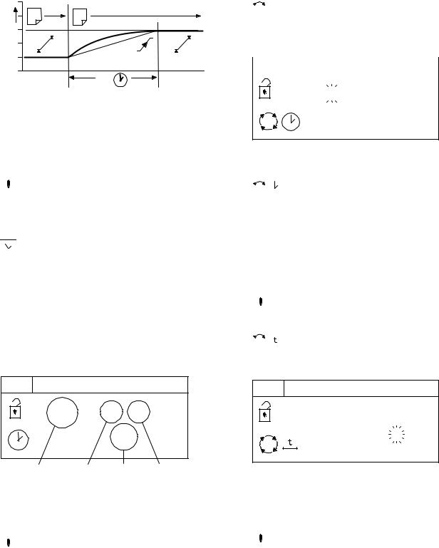
Simply stated, pressure control is achieved by unloading and loading compressors to closely match compressor output with system demand within a specified pressure band defined by PL and PH. See Figure 1.
Variable speed compressors also operate within the pressure band and actively match compressor output with system demand by speeding up and slowing down around a target pressure defined by the exact midpoint of the pressure band defined by PT. See Figure 2.
a |
PH |
|
|
|
PT |
|
PL |
|
b |
Figure 1 — Typical System Pressure vs. Time
As pressure rises to point “a”, the compressor will unload based on the sequencing algorithm. System pressure is then allowed to decrease due to the drop in supply until point “b” is reached. Once point “b” is reached, the X12I will load the next compressor in the sequence to match the air demand. This cycle will repeat as long as the X12I is able to keep the system air pressure between PH and PL.
PH |
PT |
PL |
Figure 2 — Typical VSD Pressure Control vs. Time
The variable speed compressors in the system will run on their target pressure and smooth out the variations in system pressure. This assumes that system demand does not vary more than the capacity of the variable speed compressor.
A variable speed compressor will be included in the load/unload sequence and be controlled exactly as a fixed speed machine with the exception of speed control to maintain target pressure.
ANTI-CYCLING CONTROL
The most efficient way to utilize most air compressors is either fully loaded or off, with the exception of variable speed compressors which can operate efficiently at reduced loading. Compressor cycling (start-load-unload- stop, etc.) is essential to maintain pressure control. Excessive cycling, however, can result in poor compressor efficiency as well as increased maintenance.
Anti-cycling control is incorporated to help ensure that only the compressors that are actually required are started and operating while all others are kept off. Anticycling control includes a pressure tolerance range or band, defined by the user, which is outside of the primary pressure band. Inside the tolerance band, an active control algorithm continually analyzes pressure dynamics to determine the last possible second to add or cycle another compressor into the system. This control is further enhanced by the ability to fine tune the tolerance band settings and algorithm processing time (Damping).
21

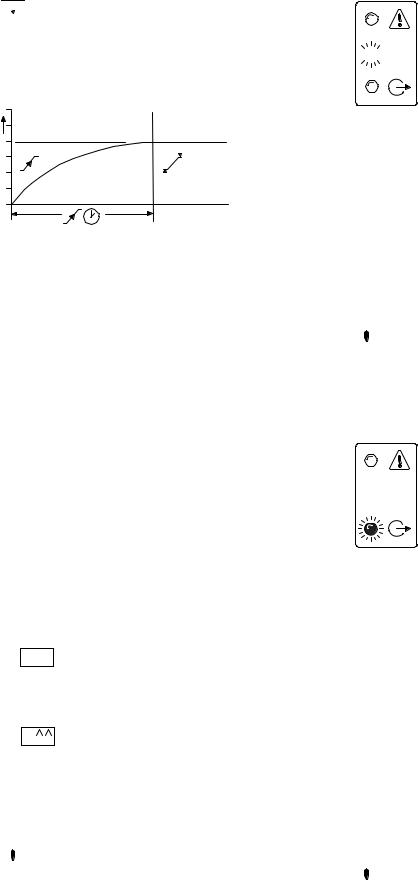
TOLERANCE
Tolerance is a user adjustable setting that determines how far above the PH Setpoint and below the PL Setpoint system pressure will be allowed to stray. Tolerance keeps the X12I from overcompensating in the event of a temporary significant increase or decrease in system demand.
PH + TO |
TO |
PH |
PT |
PL |
TO |
PL - TO |
Figure 3 — Tolerance in Relation to PH and PL
Tolerance (TO) is expressed as a pressure defining the width of the band above PH and below PL in which energy efficient control will be in effect.
When system pressure is in the tolerance band, the X12I will continuously calculate the moment at which compressors will be loaded or unloaded based on the rate of change of system pressure. When the system pressure strays outside of the tolerance band, the X12I will abandon energy efficiency and begin to protect the system air pressure by loading or unloading the compressors. Loading will be delay controlled.
When the compressed air system storage is relatively small compared to the system demand, and fluctuations are large and quick, the tolerance band setting should be increased to maintain energy efficient operation and avoid a situation in which multiple compressors are loaded just to be unloaded moments later.
When the compressed air system is relatively large compared to system demand and fluctuations are smaller and slower, the tolerance band can be reduced to improve pressure control and maintain energy efficient operation.
The factory default setting for tolerance is 3.0 PSI (0.2Bar). This setting is user adjustable.
DAMPING
Any time the pressure is within the Tolerance band the Anti-Cycling algorithm is active, sampling the rate of pressure change and calculating when to load or unload the next compressor. The damping (DA) setting is a user adjustable Setpoint that determines how quickly the controller samples and recalculates, effectively speeding up or slowing down the reaction time.
The X12I’s factory default DA setting of “1” is adequate for the majority of compressed air systems but may need to be adjusted in the following circumstances involving aggressive and disproportionate system pressure changes:
•Inadequate air storage
•High pressure differential across the air treatment equipment
•Incorrectly sized piping
•Slow or delayed compressor response
In these circumstances, the X12I may overreact and attempt to load additional compressors that may not be necessary if the system was given time to allow the system pressure to stabilize after the initial compressor is given time to load. If the tolerance has already been increased and the X12I is still overreacting, then increasing the damping factor is the next step.
Damping is adjustable and is scaled from 0.1 to 10 with a factory default of 1. A factor of 0.1 is a reaction time 10 times faster than the default and a factor of 10 is a reaction time 10 times slower than the default.
 There are many variables that go into determining the stability and control of the system pressure, only some of which are able to be controlled by the X12I. System storage, air compressor capacity, and air demand all need to be analyzed by experienced professionals to determine the best installation for your system. Tolerance (TO) and damping (DA) can be used for minor tuning of the system.
22

SYSTEM VOLUME
- |
+ |
Assorted Receiver Tanks
System volume defines how fast system pressure will rise or fall in reaction to either increased/decreased demand or increased/decreased supply. The larger the system volume, the slower the pressure changes in relation to increased/decreased demand or supply. Adequate system volume enables effective pressure control and avoids system over-pressurization in response to abrupt pressure fluctuations. Adequate system volume is created by correctly sizing and utilizing air receivers.
The most accurate way to determine the size of air receivers or the additional volume required would be to measure the size and duration of the largest demand event that occurs in the system, then size the volume large enough to ride through the event with an acceptable decrease in system pressure. Sizing the volume for the worst event will ensure system stability and effective control over all other normal operating conditions.
If measurement is not available, then estimating the largest event is a reasonable alternative. For example, assume that the largest demand event could be equal to the loss of the largest operating air compressor. System volume would be sized to allow time for a back-up compressor to be started and loaded with an acceptable decrease in pressure.
Storage Calculations:
The following formula determines the recommended minimum storage volume for a compressed air system:
V — “Volume of Required Storage” (Gal, Ft3, m3, L) T — “Time to Start Back-up Compressor” (Minutes)
C — “Lost Capacity of Compressed Air” (CFM, m3/min) Pa — “Atmospheric pressure” (PSIa, BAR)
∆P — “Allowable Pressure Drop” (PSI, BAR)
Example 1: Find Required Storage Volume in Ft3 and US Gal.
(4) - 100 Hp Compressors at 450 CFM (12.7 m3) each 15 seconds to start and load a compressor.
5PSIG is the maximum allowable pressure drop. T=15 Seconds (.25 minute)
C=450 ft3
Pa = 14.5 PSI
Delta P = 5 PSI
V = [.25 x (450 x 14.5)]/5 V = (.25 x 6525)/5
V = 1631/5
V = 326 Ft3
1 ft3 = 7.48 Gal Gal= 326 Ft3 x 7.48 Gal = 2440
Example 2: Find Required Storage Volume in m3 and L.
(
4) - 100 Hp Compressors at 450 CFM (12.7 m3) each 15 seconds to start and load a compressor.
0.34BAR is the maximum allowable pressure drop.
T=15 Seconds (.25 minute) C=12.7 m3
Pa = 1BAR
Delta P = .34 BAR
V = [.25 x (12.7 x 1)]/.34 V = (.25 x 12.7)/.34
V = 3.2/.34
V = 9.33m3 1m3 = 1000 L
L= 9.33 m3 x 1000 L = 933
23
SEQUENCE CONTROL STRATEGIES
The X12I provides three basic sequence control strategies or modes. Each sequence control strategy consists of two sub strategies:
1)The compressor ‘Rotation’ strategy
2)The compressor load ‘Control’ strategy

 The ‘Rotation’ strategy defines how the compressors are re-arranged, or re-ordered, in to a new sequence at each routine ‘Rotation’ event. Rotation events are triggered by a cyclic interval time, a set time of day each day, or a set time of day once a week.
 The compressor load ‘Control’ strategy defines how the compressors are utilized in response to variations in system pressure.
Compressor Sequence Arrangements:
Each compressor in a system is initially assigned to the X12I with a fixed and unchanging number reference, 1 to 12.
The ‘duty’ that a compressor is assigned in any set ‘Rotation’ sequence arrangement is defined by a letter, A to L.
For example:
A = the ‘Duty’ compressor, the first to be utilized.
B = The ‘Standby’ compressor, the second to be utilized. C = The ‘Second Standby’ compressor, the third to be utilized.
D = The ‘Third Standby’ compressor, the forth to be utilized.
Compressor ‘duty’ assignments are reviewed, and rearranged as appropriate in accordance with the selected rotation strategy, at each rotation event.
STANDARD CONTROL FEATURES AND FUNCTIONALITY
The standard (default) configuration of the X12I provides ENER (Energy Control) sequence control strategy, Priority Settings, Table Selection, Pressure Schedule, and Pre-fill operation.


 ENER: ENERGY CONTROL MODE
The primary function of Energy Control mode is to:
1/ Dynamically match compressed air supply with compressed air demand.
2/ Utilize the most energy efficient set/combination of air compressors to achieve 1/.
Energy Control mode is designed to manage systems that include compressors of different capacities and different air compressor types (fixed speed, variable speed and variable capacity) in any combination or configuration.
Energy Control Mode Control and Rotation:
Compressor control and utilization is dynamically automated with adaptive control logic and therefore does not follow pre-determined schedules, rotation configurations or time intervals. Energy Control mode can, however be operator influenced by the Priority functionality which is discussed later in this manual.
Energy Control mode is enabled by the ability of the X12I to process individual compressor capacity, variable capacity capabilities, and changes in system pressure to dynamically implement and continuously review ‘best fit’ configurations as demand variations occur.
100% 
80% 
2 |
|
|
40% |
|
|
20% |
|
|
0% |
|
|
0% |
1 |
100% |
1:Demand
2:Supply
PRIORITY SETTINGS


 The sequence assignment pattern can be modified by using the priority settings.
Priority settings can be used to modify the rotation sequence assignments. Compressors can be assigned a priority of 1 to 12, where 1 is the highest priority. Any compressor can be assigned any priority and any number of compressors can share the same priority.
Priorities allow you to set up rotation groups. All compressors that have the same priority number will rotate inside their own group. The group with the highest priority will always be in the front of the sequence.
For example, in a four compressor system including one variable speed compressor in the compressor 1 position you may want the variable speed compressor to always be in the Lead position. By assigning compressor 1 a priority of 1 and the other three compressors a priority of 2, the variable speed compressor will always remain at the front of the sequence:
|
1 |
2 |
3 |
4 |
|
1 |
2 |
2 |
2 |
#1 |
A |
B |
C |
D |
#2 |
A |
C |
D |
B |
#3 |
A |
D |
B |
C |
#4 |
A |
B |
C |
D |
Compressor 1 has priority 1, all other compressors have priority 2
24
In another example, there is a four compressor system that includes a compressor in the compressor 4 spot that is used only as an emergency backup compressor. To accomplish this, simply assign compressor 4 a lower priority than any other compressor in the system:
|
1 |
2 |
3 |
4 |
|
1 |
1 |
1 |
2 |
#1 |
A |
B |
C |
D |
#2 |
B |
C |
A |
D |
#3 |
C |
A |
B |
D |
#4 |
A |
B |
C |
D |
Compressor 4 has priority 2, all other compressors have priority 1
In a third example, there is a four compressor system that includes a variable speed compressor designated compressor 1 and a fixed speed compressor that is an emergency backup assigned as compressor 4. To ensure that compressor 1 is always at the front of the sequence and compressor 4 is always at the end of the sequence, set the priority as shown below:
|
1 |
2 |
3 |
4 |
|
1 |
2 |
2 |
3 |
#1 |
A |
B |
C |
D |
#2 |
A |
C |
B |
D |
#3 |
A |
B |
C |
D |
#4 |
A |
C |
B |
D |
Compressor 1 has priority 1, compressor 4 has priority 3 and all other compressors have priority 2
A last example involves another four compressor system that will be assigned into two independently rotation groups. Compressors 1 and 2 are given priority 1 and compressors 3 and 4 are given priority 2. This results in the rotation sequence shown below:
|
1 |
2 |
3 |
4 |
|
1 |
1 |
2 |
2 |
#1 |
A |
B |
C |
D |
#2 |
B |
A |
D |
C |
#3 |
A |
B |
C |
D |
#4 |
B |
A |
D |
C |
Two independently rotating compressor groups
•PL – Low Pressure Setpoint
•Pm – Minimum pressure warning level
•SQ – Sequence Rotation Strategy
•01 – Compressor 1 Priority
•to
•12 – Compressor 12 Priority
 The “maximum” pressure fault level and the rotation interval, or rotation time, are set independently in a configuration menu and are unchanging regardless of the table selected.
25
PRESSURE CHANGE TIME:
When the X12I is instructed to change between tables, it will not abruptly change the system operating parameters. The X12I will adjust the system target pressure upward or downward to the next table’s settings. This transition will occur gradually to preserve energy efficiency and safe, reliable control:
1 |
2 |
|
PC |
Changing Target Pressures
The time the system is allotted to change the target pressure is known as the Pressure Change Time (PC). This is a value that is adjustable in the system settings screen.
If the X12I is able to complete the transition in less time than is allotted without threatening energy efficiency then PC will be automatically shortened.
 An aggressively short time setting will compromise energy efficiency.
PRESSURE SCHEDULE:


 The X12I is equipped with a real time clock feature and pressure schedule facility. The ‘Pressure Schedule’ function can be used to provide automation of the system.
The pressure schedule consists of 28 individual settings that instruct the system to change from one ‘Table’ to another, or put the system in to ‘Standby’ mode, dependant on time of day and day of the week. The pressure schedule will cycle from 00:00 hours Monday (day #1) to 23:59 hours on Sunday (day #7) each calendar week.
P01 |
01.0# |
|
|
01 |
|
# - |
|
- - : - - |
|
|
|
|
- - - |
|
0# = |
01 |
02 |
04 |
03 |
01) Day of the Week
#1 = Monday to #7 = Sunday
#8 = every working day of the week; Monday to Friday, excluding Saturday and Sunday.
#9 = every working day of the week.
 Select “-“ (dash) and enter to delete a setting from the schedule.
02) Hours; time of day (24hr format)
03) Minutes; time of day
04) The required table, T01 to T04, or
“-X-“ = Standby (unload all compressors).
Adjust the ‘day of the week’ sub-setting first and then press Enter to increment to the next setting. Repeat until all item sub-settings are entered. The complete ‘Pressure Schedule’ item will not be set in X12I memory until the last sub-setting is entered. Press Escape to step back one sub-item if required.
SEQUENCE ROTATION:

 A sequence ‘Rotation’ event can be automatically triggered on a routine basis using a pre-determined interval, a pre-determined time each day or a predetermined day and time each week.
S01 |
04.01 |
RP |
 #1
#1 18:00
18:00
Enter the rotation period menu item (RP); the ‘day’ setting will flash.

 Select the ‘day’ or day function as required:
#1 = Monday to #7 = Sunday
#8 = each working day of the week, excluding Saturday and Sunday
#9 = each working day of the week.
#- (dash) = deactivate
Select the required hour and minutes of the day(s) using the same method.
 A day starts at 00:00hrs and ends at 23:59hrs (24hr clock system).


 To define an interval time (more than one rotation event a day) select ‘#t’ for the day function and press Enter:
S01 04.02 |
RP |
# t |
12:00 |
|
2 |
An ‘intervals per day’ value will appear and flash. Select the required number of rotation events per day (1 to 96). The hour and minutes display will now show the interval time between each rotation event; 1 = every 24hrs to 96 = every 15 minutes (example: 2 = every 12hrs).
 The first automated rotation event each day will occur at 00:00hrs and then every set rotation interval time throughout the day.
26
PREFILL

 The Prefill feature provides a controlled and energy efficient method of increasing pressure to normal operating levels at system start. This feature avoids the inefficient potential for all available system compressors to start and load before pressure reaches the normal operating level.
At system start (manual start or automated start from standby) the X12I will only load compressors that have been pre-determined for prefill operation, for a pre-set period of time. The prefill time (PT) can be adjusted to suit system characteristics. The aim is to increase pressure to normal operational levels, using only the predetermined compressors, prior to the prefill time expiring.
If normal operational pressure is reached prior to the set prefill time, the prefill function will automatically cease and normal operational control begin. If normal operational pressure is not reached by the end of the prefill time, the X12I will utilize as many available compressors as required to achieve normal operational pressure as quickly as possible. Normal operational control will then begin.
Three prefill modes are available. ‘Backup’ and ‘Standard’ modes require compressor pre-selection and function in the same way; differing only in response to a failure, or loss, of a prefill compressor. Automatic mode requires no compressor pre-selection.
 Backup Mode: Compressor(s) can be pre-selected as ‘Primary Prefill’ compressor(s) or ‘Backup Prefill’ compressor(s). If a primary prefill compressor experiences a shutdown, or is stopped, a pre-defined backup compressor replaces it and prefill continues.
 !
!  X Standard Mode: If one or more of the predefined prefill compressors experiences a shutdown, or is stopped, the prefill function is cancelled and normal operation begins.
 A Automatic Mode: No Prefill compressor selection is necessary; any selection set is ignored. The management unit automatically selects compressor(s) dynamically to achieve pressure in accordance with the set Prefill time. If a compressor is stopped, or shuts down, it is automatically substituted with an alternative compressor.
 To manually skip Prefill mode, press and hold Start for several seconds.
INSUFFICIENT CAPACITY ALARM


 CAP
CAP
The X12I is equipped with a dedicated ‘Insufficient Capacity’ Advisory Alarm (Warning) indication. This indication will illuminate if all available compressors are loaded and system pressure is continuing to decrease. The indication will generally occur prior to any set low pressure Alarm (Warning) and is intended to provide an advanced warning of a potential ‘Low Pressure’ situation.
The ‘Insufficient Capacity’ advisory alarm is intended as an advanced warning and is not recorded in the fault history log but is included as a Group Alarm (Warning), or Group Fault item.
‘Insufficient Capacity’ is available as a dedicated data communications item.
 The ‘Insufficient Capacity’ advisory alarm function can be de-activated. In this instance the unit’s Alarm indicator will still illuminate but no group alarm, group fault, or a remote indication is generated.
RESTRICTED CAPACITY ALARM
 CAP
CAP
The X12I is equipped with a dedicated ‘Restricted Capacity’ Advisory Alarm (Warning) indication. This indication will flash if all available compressors are loaded and further capacity is required but one or more, compressors are:
a)inhibited from use in a ‘Table’ priority setting
b)inhibited from use by the short-term Service / Maintenance function
c)inhibited from use in the long term maintenance menu.
The ‘Restricted Capacity’ advisory alarm is intended to indicate that all available compressors are already loaded and further capacity is required but one or more, system compressor(s) have been restricted from use.
The ‘Restricted Capacity’ advisory alarm is not recorded in the fault history log but is included as a Group Alarm (Warning), or Group Fault item.
‘Restricted Capacity’ is available as a dedicated data communications item.
 The ‘restricted capacity’ advisory alarm function can be de-activated. In this instance the unit’s alarm indicator will still flash but no group alarm, group fault, or a remote indication is generated.
27
ALTERNATE CONTROL STRATEGIES
Energy Control Mode (ENER) is the STANDARD control mode of the X12I. Alternate control strategies of the X12I are EHR (Equal Hours Run) and the basic FILO (First in / Last Out).


 EHR: EQUAL HOURS RUN MODE
The primary function of EHR mode is to maintain a close relationship between the running hours of each compressor in the system. This provides an opportunity to service all compressors at the same time (providing the service interval times for all compressors are the same or similar).
 EHR is not an energy efficient focused mode of operation.
EHR Rotation:
Each time the rotation interval elapses, or the rotation time is reached, the sequence order of compressors is reviewed and re-arranged dependant on the running hours recorded for each compressor. The compressor with the least recorded running hours is assigned as the ‘duty’ compressor, the compressor with the greatest recorded running hours is assigned as the ‘last standby’ compressor. For systems with more than two compressors, the remaining compressor(s) are assigned in accordance with their recorded running hours in the same way.
Example: The compressors in a four-compressor system have the following recorded running hours at the ‘Rotation’ time.
Compressor 1 = 2200 hrs
Compressor 2 = 2150 hrs
Compressor 3 = 2020 hrs
Compressor 4 = 2180 hrs
The new sequence order arrangement after a rotation event would be:
Compressor 1 = D
Compressor 2 = B
Compressor 3 = A
Compressor 4 = C
Compressor 3, which has the least recorded running hours, will now be utilized to a greater extent in the new sequence arrangement; potentially increasing the running hours at a faster rate.
The X12I continuously monitors the running status of each compressor and maintains a record of the accumulated running hours. These are available, and adjustable, in the X12I’s compressor running hour’s menu. The X12I uses these values in EHR mode. The X12I’s running hours record should be routinely checked, and adjusted if necessary, to ensure a close match with the actual run hours displayed on each compressor.
 If a compressor is operated independently from the X12I the running hours record may not be accurately updated.
 The running hours meter display on most compressors are intended for approximate service interval indication only and may deviate in accuracy over a period of time.
EHR Control:
Compressors are utilized, in response to changing demand, using a ‘FILO’ (First In, Last Out) strategy. The ‘duty’ compressor (A) is utilized first followed by (B) if demand is greater than the output capacity of (A). As demand increases (C) is utilized followed by (D) if demand increases further. As demand reduces (D) is the first compressor to be unloaded, followed by (C) and then
(B) if demand continuous to reduce. The last compressor to be unloaded, if demand reduces significantly, is (A). The compressor assigned as (A) in the sequence is the first to be loaded and the last to be unloaded.


 FILO: TIMER ROTATION MODE
The primary function of Timer Rotation mode is to efficiently operate a compressed air system consisting of fixed capacity output compressors. The routine rotation assignments can be modified using ‘Priority’ settings to accommodate for a differentially sized or variable capacity output compressor(s).
FILO Rotation:
Each time the rotation interval elapses, or the rotation time is reached, a sequence rotation occurs and the sequence assignment for each compressor is rearranged. The compressor that was assigned for duty (A) is re-assigned as last standby (D) and all other compressor assignments are incremented by one.
|
1 |
2 |
3 |
4 |
#1 |
A |
B |
C |
D |
#2 |
D |
A |
B |
C |
#3 |
C |
D |
A |
B |
#4 |
B |
C |
D |
A |
The sequence assignment pattern can be modified by ‘Priority’ settings.
 Tables; Priority Settings
FILO Control:
Compressors are utilized, in response to changing demand, using a ‘FILO’ (First In, Last Out) strategy.
The ‘duty’ compressor (A) is utilized first followed by (B) if demand is greater than the output capacity of (A). As demand increases (C) is utilized followed by (D) if demand increases further.
As demand reduces (D) is the first compressor to be unloaded, followed by (C) and then (B) if demand continues to reduce.
The last compressor to be unloaded, if demand reduces significantly, is (A). The compressor assigned as (A) in the sequence is the first to be loaded and the last to be unloaded.
28
 Loading...