


Ingersoll Rand
X-IRI Communications Gateway
Operators Manual
Before installing or starting this unit for the first time, this manual should be studied carefully to obtain a working knowledge of the unit and/or the duties to be performed while operating and maintaining the unit.
RETAIN THIS MANUAL WITH UNIT. This Technical manual contains IMPORTANT SAFETY DATA and should be kept with the unit at all times.
More Than Air. Answers.
Online answers: http://www.air.irco.com
C.C.N. : |
80445596 |
REV. |
A |
DATE: |
June 2009 |
SECTION 1 — TABLE OF CONTENTS
SECTION 1 — TABLE OF CONTENTS................................ |
1 |
SECTION 2 — INTRODUCTION ....................................... |
2 |
SECTION 3 — SAFETY..................................................... |
2 |
SAFETY PRECAUTIONS .................................................... |
2 |
INSTALLATION ................................................................ |
2 |
OPERATION .................................................................... |
2 |
MAINTENANCE AND REPAIR........................................... |
3 |
SECTION 4 — COMPRESSOR CONNECTION AND CONTROL |
|
..................................................................................... |
4 |
COMPRESSOR CONNECTION AND CONTROL.................. |
4 |
INTELLISYS SOFTWARE REQUIREMENTS......................... |
4 |
MODBUS RTU ................................................................. |
5 |
SECTION 5 — INSTALLATION ......................................... |
8 |
UNIT LOCATION.............................................................. |
8 |
POWER SUPPLY .............................................................. |
8 |
DCS OR PLC CONNECTION .............................................. |
9 |
COMPRESSOR IR BUS CONNECTION .............................. |
9 |
DCS OR PLC COMMUNICATIONS .................................. |
10 |
COMPRESSOR COMMUNICATIONS: ............................. |
10 |
OPERATIONAL INDICATIONS ........................................ |
10 |
RS 485 NETWORK......................................................... |
12 |
MODBUS ADDRESS SELECTION..................................... |
13 |
MODBUS PORT SETUP SELECTION................................ |
14 |
GATEWAY SOFTWARE VERSION DISPLAY ..................... |
15 |
COMMISSIONING PROCEDURE .................................... |
16 |
SECTION 6 PARTS LIST ............................................... |
17 |
SECTION 7 TECHNICAL DATA ..................................... |
17 |
SECTION 8 – INTELLISYS MODBUS TABLES .................... |
18 |
TABLE 1 SSR (REDEYE) CONTROLLER ............................ |
18 |
TABLE 2 SSR (SG) CONTROLLER .................................... |
21 |
TABLE 3 SSR (SE) 15 100HP CONTROLLER .................... |
26 |
TABLE 4 SIERRA (REDEYE) 125 200 HP CONTROLLER ... |
29 |
TABLE 5 SIERRA (SE) 50 100 HP CONTROLLER.............. |
32 |
TABLE 6 SIERRA (SG) 125 400 HP CONTROLLER ........... |
35 |
TABLE 7 SSR (SG) CONTACT COOLED RETROFIT |
|
CONTROLLER................................................................ |
39 |
TABLE 8 RECIP (REDEYE) CONTROLLER......................... |
44 |
TABLE 9 RECIP (SG) CONTROLLER................................. |
48 |
TABLE 10 RECIP BOOSTER (REDEYE) CONTROLLER....... |
52 |
TABLE 11 NIRVANA (SGN) CC (CONTACT COOLED) |
|
CONTROLLER................................................................ |
56 |
TABLE 12 NIRVANA (SGNE) CC (CONTACT COOLED) |
|
CONTROLLER................................................................ |
60 |
TABLE 13 NIRVANA SGNE OF (OIL FREE) CONTROLLER65 |
|
TABLE 14 SSR UP (SE) CONTROLLER............................. |
69 |
TABLE 15 ESA (SE) 22 – 150 KW CONTROLLER ............. |
72 |
TABLE 16 R SERIES (S3) CONTROLLER.......................... |
75 |
TABLE 17 NIRVANA 15 30 KW (20 40 HP) DF |
|
CONTROLLER................................................................ |
77 |
Refer to Section Indicated
Note
Important or Caution, Safety
1
SECTION 2 — INTRODUCTION
The X-IRI Communication Gateway is designed to interface the Intellisys Controllers on Ingersoll Rand Compressors with a Distributed Control System (DCS), Programmable Logic Controller (PLC), or any other device that is capable of communicating using the MODBUS RTU communications protocol.
The X-IRI provides MODBUS connectivity to Ingersoll Rand controllers that do not have built-in MODBUS capability. The X-IRI also provides address filtering and communication buffering capabilities to protect the integrity of the serial data network.
The X-IRI is designed to be DIN Rail mounted within the compressor control gear enclosure but can alternatively be mounted remotely within a separate enclosure.
SECTION 3 — SAFETY
SAFETY PRECAUTIONS
!WARNING : Risk of Danger
WARNING : Risk of Electric Shock
! |
WARNING : Risk of High Pressure |
|
|
|
WARNING : Consult Manual |
•Before installing or operating the X-IRI GATEWAY, take time to carefully read all the instructions contained in this manual, all compressor manuals, and all manuals of any other peripheral devices that may be installed or connected to the unit.
•Electricity and compressed air have the potential to cause severe personal injury or property damage.
•The operator should use common sense and good working practices while operating and maintaining this system. All applicable codes should be strictly adhered to.
•Maintenance must be performed by adequately qualified personnel that are equipped with the proper tools.
INSTALLATION
•Installation work must only be carried out by a competent person under qualified supervision.
•A fused isolation switch must be fitted between the main power supply and the X-IRI GATEWAY.
•The X-IRI GATEWAY should be mounted in such a location as to allow operational and maintenance access without obstruction or hazard and to allow clear visibility of indicators at all times.
•If raised platforms are required to provide access to the X-IRI GATEWAY, they must not interfere with normal operation or obstruct access. Platforms and stairs should be of grid or plate construction with safety rails on all open sides.
OPERATION
•The X-IRI GATEWAY must only be operated by competent personnel under qualified supervision.
•Never remove or tamper with safety devices, guards or insulation materials fitted to the X-IRI GATEWAY.
•The X-IRI GATEWAY must only be operated at the supply voltage and frequency for which it is designed.
•When main power is switched on, lethal voltages are present in the electrical circuits and extreme caution must be exercised whenever it is necessary to carry out any work on the unit.
•Do not open access panels or touch electrical components while voltage is applied unless it is necessary for measurements, tests or adjustments. Such work should be carried out only by a qualified electrician equipped with the correct tools and wearing appropriate protection against electrical hazards.
•All air compressors and/or other equipment connected to the unit should have a warning sign attached stating “THIS UNIT MAY START WITHOUT WARNING” next to the display panel.
•If an air compressor and/or other equipment connected to the unit is to be started remotely, attach two warning signs to the equipment stating “THIS UNIT CAN BE STARTED REMOTELY”. Attach one sign in a prominent location on the outside of the equipment, and the other sign inside the equipment control compartment.
2

MAINTENANCE AND REPAIR
•Maintenance, repairs or modifications must only be carried out by competent personnel under qualified supervision.
•If replacement parts are required, use only genuine parts from the original equipment manufacturer, or an alternative approved source.
•Carry out the following operations before opening or removing any access panels or carrying out any work on the X-IRI GATEWAY:
i.Isolate the X-IRI GATEWAY from the main electrical power supply. Lock the isolator in the “OFF” position and remove the fuses.
ii.Attach labels to the isolator switch and to the unit stating “WORK IN PROGRESS - DO NOT APPLY VOLTAGE”. Do not switch on electrical power or attempt to start the X-IRI GATEWAY if such a warning label is attached.
•Make sure that all instructions concerning operation and maintenance are strictly followed and that the complete unit, with all accessories and safety devices, is kept in good working order.
•The accuracy of sensor devices must be checked on a regular basis. They must be calibrated when acceptable tolerances are exceeded. Always ensure any pressure within the compressed air system is safely vented to atmosphere before attempting to remove or install a sensor device.
•The X-IRI GATEWAY must only be cleaned with a damp cloth, using mild detergents if necessary. Avoid the use of any substances containing corrosive acids or alkalis.
•Do not paint the control faceplate or obscure any indicators, controls, instructions or warnings.
3
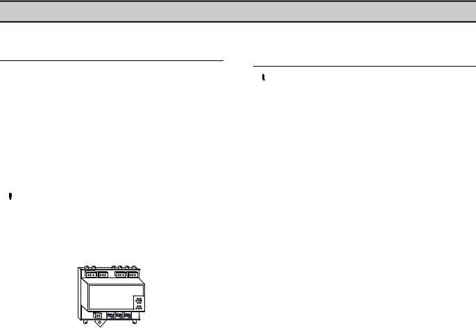
SECTION 4 — COMPRESSOR CONNECTION AND CONTROL
COMPRESSOR CONNECTION AND CONTROL
The X-IRI Gateway module is designed to interface to any Ingersoll Rand Intellisys controlled compressor. All Ingersoll Rand compressors equipped with Intellisys controllers must use this interface when communicating with MODBUS masters.
The X-IRI gateway prevents the compressor controller from seeing any communications that aren’t directed toward the controller’s network address. Additionally, the X-IRI will buffer communications so that the compressor controller will not receive a command greater than once every 500 milliseconds.
 Setting a MODBUS polling rate of less than 500 milliseconds will not cause a quicker response from X-IRI.
The PLC or DCS communicates to the X-IRI Gateway via a two wire, RS-485 network utilizing the MODBUS RTU protocol.
The X-IRI Gateway module is installed within the compressor control cabinet and connected to the PLC or DCS using Belden 9841 or equivalent RS-485 cable.
INTELLISYS SOFTWARE
REQUIREMENTS
 Each Intellisys controller must have its controller software revision at or above a certain minimum level to work with the IRI.
The machine types and required software EPROM minimum version levels are listed below. Check the machine to be connected to an IRI for the appropriate EPROM. If the EPROM is not of the correct minimum version level, the appropriate EPROM may be ordered from your local Ingersoll Rand Distributor or Air Center.
Machine Type EPROM Minimum Version Level |
|
SSR 50-450 Horsepower - 1 stage (Red Eye) |
2.3 |
SSR 50-450 Horsepower - 2 stage (Red Eye) |
2.3 |
SSR SG |
1.0 |
15-50 Horsepower |
1.4 |
Sierra 50-100 Horsepower (SE) |
1.2 |
Sierra 100-200 Horsepower (Red Eye) |
2.5 |
Sierra 125-400 HP SG |
1.0 |
Recip (Red Eye) |
1.6 |
Recip SG |
1.0 |
Nirvana SGN |
1.0 |
Nirvana SGNe CC |
2.0 |
Nirvana SGNe OF |
1.0 |
Pegasus |
1.0 |
ESA SE 22-150 KW |
1.6 |
When monitoring compressor data only, no options are required to be installed in the Intellisys controller. If machine control is desired, the Remote Start/Stop and Sequence options must be installed and turned "On".
4

MODBUS RTU
MODBUS Table(s)
This document discusses generic MODBUS communications and how to implement the software specific ‘MODBUS Table’ information. MODBUS communication formatting may differ from controller to controller and you may require more than one ‘MODBUS Table’.
Always check the software variant identification and version number for a controller with the variant and version of the ‘MODBUS Table’ supplied. In some instances the information contained in a ‘MODBUS Table’ may not be applicable to a controller installed with the same software variant but a different version number.
General
MODBUS RTU (Remote Terminal Unit) is a master-slave type protocol. An Intellisys Controller functions as the slave device. Information requests or commands are communicated from master to slave only through the X-IRI. The X-IRI will always respond to communications from a remote master device in accordance with the MODBUS RTU protocol standard.
The MODBUS protocol is used to communicate with personal computers (PC), Programmable Logic Controllers (PLC’s), or Distributed Control Systems (DCS) over the Network port. The X-IRI only responds to two MODBUS commands, Read Holding Register 03 (03 Hex) and Preset Single Register 06 (06 Hex). (See Modicon MODBUS Protocol Reference Guide, PI-MBUS-300 Rev. J or later, for more details on MODBUS).
Communication Link
MODBUS is implemented using a two-wire RS485 industry standard communications link operating in master-slave mode.
 Polarity of the two RS485 wires (L1+ and L2-) is important; reversal will disrupt communications.
RS485 Serial Data Format
The RS485 MODBUS port is a 2-wire operating with an asynchronous serial data format: 8 data bits / no parity / 1 or 2 stop bits (8,N,1 or 8,N,2) - transmitted at 9600 baud.
Message Data Format
The bytes of the MODBUS RTU message must be sent in one message package. The RTU protocol allows for a maximum pause of 1.5 byte-times between 2 consecutive bytes of a message.
 A pause longer than 1.5 byte-times will render the message invalid and it will be ignored.
Message data format is dependent on function and will consist of a combination of the following elements:
1)Destination address (slave network address)
2)Function Code
3)Data start address (slave register start address)
4)Number of registers, number of bytes of data
5)Message data
6)CRC checksum
Message Destination Address
The ‘destination address’ must be correct for the ‘slave’ controller device for which the message is intended. An address can be from 1 to 127 decimal (01Hex to 7FHex). The SMG Box is transparent and addresses must be for the destination ‘slave’ controller or unit. Each controller or unit must be set with a unique address.
Slave |
Function |
Start |
Number of |
CRC Check |
Address |
Code |
Address |
Registers |
Sum |
|
|
|
|
|
22 |
03 |
00 6F |
00 02 |
F3 45 |
Slave Address = 22Hex = 34 Decimal
Message Function Codes
The message function code defines the required data processing operation of the slave controller. Although several types of message function codes are defined by the MODBUS standard, only the message function code types working directly with registers are implemented on controller units:
03H Read Holding Register(s) – Read
06H Preset Single Register - Write
Slave |
Function |
Start |
Number of |
CRC Check |
Address |
Code |
Address |
Registers |
Sum |
|
|
|
|
|
22 |
03 |
00 6F |
00 02 |
F3 45 |
Function Code = 03 = Read Holding Register
 Any other message function code type will result in an EXCEPTION response.
5

Message Data Start Address
The message data start address (16bit word) designates the initial register address location in the controller from which the data is processed. Start address information is contained in the ‘MODBUS Table’.
Slave |
Function |
Start |
Number of |
CRC Check |
Address |
Code |
Address |
Registers |
Sum |
|
|
|
|
|
22 |
03 |
00 6F |
00 02 |
F3 45 |
Start Address = 6F = 40112
 High-byte transmitted first followed by low-byte.
Message Data
The message data content depends on the message function code type.
03H Read Holding Register(s)
The Number of Registers designates the 16bit integer value that determines the size (in 16bit ‘word’ registers) of the message data being requested. This is the number of 16bit registers to read. This information is contained in the ‘MODBUS Table’.
 A maximum of 32 registers can be read at one time.
Slave |
Function |
Start |
Number of |
CRC Check |
Address |
Code |
Address |
Registers |
Sum |
|
|
|
|
|
22 |
03 |
00 6F |
00 02 |
F3 45 |
The example above is a request to read offline pressure (register 40112) and online pressure (register 40113) from X-IRI address 22(Hex)
06H Preset Single Register
The Data byte 0 byte 1 designates the value of the 16bit integer word to be written to the Intellisys controller. This information is contained in the ‘MODBUS Table’.
Slave |
Function |
Start |
DATA |
CRC Check |
Address |
Code |
Address |
byte 0 byte 1 |
Sum |
|
|
|
|
|
22 |
06 |
00 6F |
00 5F |
FE BC |
The example above is a request to set offline pressure (register 40112) to 95 through X-IRI address 22(Hex).
Message CRC Checksum
The CRC (Cyclical Redundancy Check) is a check-sum generated by means of ‘A001H polynomial’.
Slave |
Function |
Start |
DATA |
CRC Check |
Address |
Code |
Address |
byte 0 byte 1 |
Sum |
|
|
|
|
|
22 |
06 |
00 6F |
00 5F |
FE BC |
The CRC is two bytes containing a 16-bit binary value (word). The CRC value is calculated by the transmitting device that appends the CRC to the end of the message. The receiving device recalculates the CRC value prior to processing of a received message and compares the result to the actual CRC value appended to the message. If the two values do not match the message is regarded as invalid.
The CRC is initiated by first preloading a 16bit register to all 1's (FFFF Hex). Then a process begins of applying each consecutive 8bit byte of the message to the register contents using an exclusive ‘OR’ calculation. The result is shifted one bit in the direction of the least significant bit (LSB), with the most significant bit (MSB) set at ‘0’. The LSB is then examined; if ‘1’ the register content is applied to the polynomial value ‘A001’ Hex (1010 0000 0000 0001) using an exclusive ‘OR’ calculation - if ‘0’ no exclusive OR takes place.
This process is repeated until eight ‘bit’ shifts have been performed. After the eighth bit shift, the next 8bit message byte is applied to the register contents using an exclusive ‘OR’ calculation. The bit shift and re-calculation process is then repeated again. When all message bytes have been processed the final content of the 16bit register is the message CRC value.
Only the 8bits of ‘data’ in each message character is used for generating the CRC; start, stop and parity bits are ignored.
 When the 16bit CRC value is appended to a message, the low order byte must be transmitted first followed by the high order byte. An incorrect or byte reversed check sum will render the message invalid and it will be ignored.
Slave Response Timeout
A slave controller may not answer immediately. Ensure the ‘slave timeout’ setting of the ‘master’ device is set to a value no less than 500ms. If the ‘slave’ device fails to receive a valid message due to a communication disruption, parity error, CRC error or other reasons, no response is given and the master must process a timeout condition in this instance. If the ‘slave’ receives a valid message that cannot be processed an exception response will be returned.
6
Message Answer From Slave to Master
The format of the ‘slave’ controller answer is similar to the original master request format; the message data content depends on the message function code type.
The ‘address’ and ‘code’ of the slave answer is identical to the original request message; the address is the ‘slave’ device address and the ‘code’ is a repeat of received function code type from the master. The remainder of the message is dependent on the requested function code type. The CRC checksum is re-calculated for the answer message characters using the specified CRC process.
03H |
Read Holding Register(s) |
|
|
|||
Slave |
Function |
Number |
DATA |
DATA |
|
|
of Data |
CRC Check |
|||||
1st Register |
2nd Register |
|||||
Address |
Code |
Bytes to |
Sum |
|||
byte 0 byte 1 |
byte 2 byte 3 |
|||||
|
|
Follow |
|
|||
|
|
|
|
|
||
|
|
|
|
|
|
|
01 |
03 |
04 |
00 5F |
00 55 |
F3 45 |
|
The example above is a request to read offline pressure 5FHex (95) (register 40112) and online pressure 55Hex (85) (register 40113) from X-IRI address 22(Hex)
06Hex - Preset Single Register
Slave |
Function |
Start |
DATA |
CRC Check |
Address |
Code |
Address |
byte 0 byte 1 |
Sum |
|
|
|
|
|
22 |
06 |
00 6F |
00 5F |
FE BC |
The example above is a request to set offline pressure (register 40112) to 95 through X-IRI address 22(Hex).
Exception Response
If the ‘slave’ device receives a request that cannot be processed an ‘exception response’ is given. An exception response message consists of the following elements:
oSlave Network Address (1 byte): Slave address identification
oFunction Code (1 byte): In a normal response, the slave repeats the function code of the original master request. All function codes have an MSB (most significant bit) of 0 (values are all below 80 hexadecimal). In an exception response, the slave sets the MSB of the function ‘code’ to 1. This makes the ‘code’ value 80 Hex greater than the received ‘code’
value from the master.
o Data (1 byte): The ‘data’ response will contain a ‘1 byte’ value exception code.
o CRC Checksum (2 byte).
Slave Address |
Function Code |
Error Code |
CRC Check Sum |
|
|
|
|
01 |
90 |
04 |
4D C3 |
Exception Codes:
01H Illegal Function Code -- The requested ‘code’ function is not supported.
02H Illegal Data Address -- The requested ‘data start address’ is not supported.
03H Illegal Data Value -- The requested ‘data’ value is not supported.
04H Function Error -- The slave cannot execute the request or the request type is inhibited.
Troubleshooting
Problem:
o No ‘slave’ response or corrupt MODBUS message
Solution:
o Check that the ‘slave’ controller is set for the anticipated slave address
o Check that all ‘slave’ controllers are set with a unique system address
o Check that the controller is set for MODBUS RTU mode (if applicable)
o Check that the ‘master’ is operating in MODBUS RTU mode
o Check that the ‘master’ baud rate, parity bit and number of stop bits are correct
o Check that the ‘master ‘response timeout is set for a minimum of 500ms
o Check that the ‘master’ is implementing the specified CRC check sum process
oCheck RS485 wiring polarity and security of connections
Problem:
o Last character of MODBUS message is corrupted
Solution:
oAdd a delay of 2ms after last character received before releasing RTS signal
Problem:
oThe MODBUS master message is reflected in the slave answer
Solution:
oInhibit RX/TX echo on ‘master’ device communications port
7

SECTION 5 — INSTALLATION
INSTALLATION
 It is recommended that installation and commissioning be carried out by an authorized and trained product supplier.
UNIT LOCATION
The X-IRI Gateway is DIN Rail mounted and can be located within the compressor control enclosure or remotely within a separate enclosure. X-IRI Gateway must be located within 33ft (10m) of the compressor controller.
 Avoid mounting the X-IRI Gateway near high voltage cables, high voltage devices or equipment or motor starter contactors.
POWER SUPPLY
The X-IRI Gateway is powered by an external 24VDC power supply. The AC supply voltage for the 24VDC power supply is derived from the compressor’s 110VAC or 230VAC internal AC supply.
24VDC
DC
|
L |
0VDC |
+V.ADJ |
N |
|
|
E |
+24VDC |
100-240VAC 50/60Hz
 N L
N L
24VDC
DC
+V.ADJ |
|
GATEWAY |
|
|
24V |
|
|
|
AC/DC |
|
|
100-240VAC |
1 |
2 |
|
|
|
|
|
50/60Hz |
|
|
|
N L |
|
X01 |
|
|
|
|
|
N L |
|
|
|
|
|
1 |
2 |
|
|
|
X01 |
+24VDC |
|
+ |
- |
|
|
|
|
0VDC |
|
|
|
The power specification for the X-IRI Gateway is 24VDC (+-10%) @ 35mA, 1W
It is possible to use the same 24VDC power supply to power multiple X-IRI Gateway devices.
 Wire polarity is important
8

DCS OR PLC CONNECTION |
|
COMPRESSOR IR-BUS CONNECTION |
|||||||||||||||||||||
|
|
|
|
|
|
|
|
|
|
|
|
|
|
|
|
|
|
|
|
|
|
|
|
|
|
|
|
|
|
|
|
|
|
|
|
|
|
|
|
|
|
|
|
|
|
|
|
|
|
|
|
|
|
|
|
|
|
|
|
|
|
|
|
|
|
|
|
|
|
|
|
|
|
|
|
|
|
|
|
|
|
|
|
|
|
|
|
|
|
|
|
|
|
|
|
|
|
|
|
|
|
|
|
|
|
|
|
|
|
|
|
|
|
|
|
|
|
|
|
|
|
|
|
|
|
|
|
|
|
|
|
|
|
|
|
|
|
|
|
|
|
|
|
|
|
|
|
|
|
|
|
|
|
|
|
|
|
|
|
|
|
|
|
|
|
|
|
|
|
|
|
|
|
|
|
|
|
|
|
|
|
|
|
|
|
|
|
|
|
|
|
 Wire polarity is important
Use 2-wire, 24 gauge (Belden 9841 or equivalent), twisted pair, earth shielded, data cable with a total system network length no greater than 4000ft (1219m).
 Wire polarity is important
Use 2-wire, 24 gauge (Belden 9841 or equivalent), twisted pair, earth shielded, data cable with a length no greater than 33ft (10m).
For IntelliSys “Red Eye”, SG and SE equipped with an RJ11 RS-485 data communications connection port, use the RJ11 Modbus cable supplied with the X-IRI Gateway.
L1 |
2 |
2 |
|
||
L2 |
|
3 |
4 |
4 |
|
|
5 |
X02
RJ11 |
L1 (2) |
|
1 |
|
|
2 |
|
|
3 |
|
|
4 |
|
|
5 |
L2 (4) |
M4 |
6 |
||
|
|
Ring Tag |
For IntelliSys SGN, SGNe and Nirvana 15-30kW (20-40HP) equipped with a Phoenix RS-485 data communications connector, use the RJ11 Modbus cable supplied with the X- IRI Gateway and modify as shown by removing the RJ11 Plug.
9
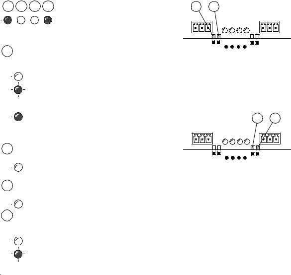
DCS OR PLC COMMUNICATIONS
 50ms
50ms
RX – Data Received:
2 |
A valid MODBUS communication has just been |
|
received from the DCS or PLC unit. In normal operation this event should occur periodically depending on the polling rate.
TX – Data Transmitted:
3 |
A MODBUS broadcast or message has just been |
|
sent. To keep the link active, a MODBUS message must be sent at least once every 10 seconds.
COMPRESSOR COMMUNICATIONS:
 50ms
50ms
RX – Data Received:
4 |
A valid IRBUS communication has just been |
|
|
received from the compressor controller. In normal |
|
operation this event should occur at least once every ½ second.
TX – Data Transmitted:
5 |
An IRBUS message has just been sent to the |
|
compressor controller. In normal operation this event should occur at least once every ½ second.
OPERATIONAL INDICATIONS
6 |
7 |
8 |
9 |
X04 |
#2 |
#3 |
|
#5 |
#4 |
X03 |
ulti485 |
|
IRMODBUS- |
||||
MODBUS |
LED |
LED |
LED#6 LED#7 LED#8 LED#9 |
LED |
LED |
|
|
|
1s
OFF |
Slow Flash |
ON |
Fast Flash |


 At power on initialization, or when power has been removed, all operational indicators will fast flash for several seconds.
10
Normal Operation Example:
When there is valid communication with a MODBUS master and an IR-BUS compatible compressor controller the main operation indicators will light up as shown below.
6 7 8 9
Normal operation function:
6Modbus Communications with MODBUS master.
OFF
No valid communications with a MODBUS master
ON: Valid communication with a MODBUS master, at least one read/write operation once every 10 seconds.
7 |
No function |
|
Always OFF: no other defined function
8 |
No function |
|
Always OFF: no other defined function
9IR-BUS communication with a compressor controller
OFF
No valid communications with the compressor controller.
ON: IR-BUS compressor controller detected and communication link established.
Led#2: Every flash indicates reception of a valid MODBUS messsage from the MODBUS master.
Led#3: Every flash indicates transmission of a valid MODBUS messsage to the MODBUS master.
Led#5: Every flash indicates transmission of a valid IRBUS messsage to the IR-BUS compressor controller.
Led#4: Every flash indicates reception of a valid IR-BUS message from the IR-BUS compressor controller.
11

RS-485 NETWORK

 RS-485 data communications and other low voltage signals can be subject to electrical interference. This potential can result in intermittent malfunction or anomaly that is difficult to diagnose. To avoid this possibility always use earth shielded cables, securely bonded to a known good earth at one end. In addition, give careful consideration to cable routing during installation.
1)Never route an RS-485 data communications or low voltage signal cable alongside a high voltage 3-phase power supply cable. If it is necessary to cross the path of a power supply cable(s), always cross at a right angle.
2)If it is necessary to follow the route of power supply cables for a short distance (for example: from a compressor unit to a wall along a suspended cable tray) attach the RS485 or signal cable on the outside of an earthed cable tray such that the cable tray forms an earthed electrical interference shield.
3)Where possible, never route an RS-485 or signal cable near to equipment or devices that may be a source of electrical interference (for example: 3-phase power supply transformer, high voltage switchgear unit, frequency inverter drive module, radio communications antenna).
12
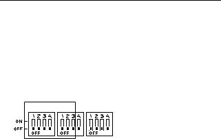
MODBUS ADDRESS SELECTION
Each compressor connected to the MODBUS network will have a unique assigned address, starting at compressor 1 increasing sequentially to the number of compressors connected to the MODBUS network. The MODBUS address is selected by using DIP switches 1, 2, 3, and 4 on SW1, and switches 1, 2, and 3 on SW2 on the X-IRI Gateway.
SW1, 1 to4 and SW2, 1 to 3: Address Selection
SW1 SW2 SW3
The addresses are selected as shown in the following table: (Note: ON = 1, OFF = 0 )
|
|
|
|
|
|
|
|
|
MODBUS |
MODBUS |
|
SW1 |
|
|
SW2 |
|
Address |
Address |
|||
1 |
2 |
3 |
4 |
1 |
|
2 |
|
3 |
(Decimal) |
(Hexl) |
0 |
0 |
0 |
0 |
0 |
|
0 |
|
0 |
1 |
1 |
1 |
0 |
0 |
0 |
0 |
|
0 |
|
0 |
1 |
1 |
0 |
1 |
0 |
0 |
0 |
|
0 |
|
0 |
2 |
2 |
1 |
1 |
0 |
0 |
0 |
|
0 |
|
0 |
3 |
3 |
0 |
0 |
1 |
0 |
0 |
|
0 |
|
0 |
4 |
4 |
1 |
0 |
1 |
0 |
0 |
|
0 |
|
0 |
5 |
5 |
0 |
1 |
1 |
0 |
0 |
|
0 |
|
0 |
6 |
6 |
1 |
1 |
1 |
0 |
0 |
|
0 |
|
0 |
7 |
7 |
0 |
0 |
0 |
1 |
0 |
|
0 |
|
0 |
8 |
8 |
1 |
0 |
0 |
1 |
0 |
|
0 |
|
0 |
9 |
9 |
0 |
1 |
0 |
1 |
0 |
|
0 |
|
0 |
10 |
A |
1 |
1 |
0 |
1 |
0 |
|
0 |
|
0 |
11 |
B |
0 |
0 |
1 |
1 |
0 |
|
0 |
|
0 |
12 |
C |
1 |
0 |
1 |
1 |
0 |
|
0 |
|
0 |
13 |
D |
0 |
1 |
1 |
1 |
0 |
|
0 |
|
0 |
14 |
E |
1 |
1 |
1 |
1 |
0 |
|
0 |
|
0 |
15 |
F |
0 |
0 |
0 |
0 |
1 |
|
0 |
|
0 |
16 |
10 |
1 |
0 |
0 |
0 |
1 |
|
0 |
|
0 |
17 |
11 |
0 |
1 |
0 |
0 |
1 |
|
0 |
|
0 |
18 |
12 |
1 |
1 |
0 |
0 |
1 |
|
0 |
|
0 |
19 |
13 |
0 |
0 |
1 |
0 |
1 |
|
0 |
|
0 |
20 |
14 |
1 |
0 |
1 |
0 |
1 |
|
0 |
|
0 |
21 |
15 |
0 |
1 |
1 |
0 |
1 |
|
0 |
|
0 |
22 |
16 |
1 |
1 |
1 |
0 |
1 |
|
0 |
|
0 |
23 |
17 |
0 |
0 |
0 |
1 |
1 |
|
0 |
|
0 |
24 |
18 |
1 |
0 |
0 |
1 |
1 |
|
0 |
|
0 |
25 |
19 |
0 |
1 |
0 |
1 |
1 |
|
0 |
|
0 |
26 |
1A |
1 |
1 |
0 |
1 |
1 |
|
0 |
|
0 |
27 |
1B |
0 |
0 |
1 |
1 |
1 |
|
0 |
|
0 |
28 |
1C |
|
|
|
|
|
|
|
|
|
MODBUS |
MODBUS |
|
SW1 |
|
|
SW2 |
|
Address |
Address |
|||
1 |
2 |
3 |
4 |
1 |
|
2 |
|
3 |
(Decimal) |
(Hexl) |
1 |
0 |
1 |
1 |
1 |
|
0 |
|
0 |
29 |
1D |
0 |
1 |
1 |
1 |
1 |
|
0 |
|
0 |
30 |
1E |
1 |
1 |
1 |
1 |
1 |
|
0 |
|
0 |
31 |
1F |
0 |
0 |
0 |
0 |
0 |
|
1 |
|
0 |
32 |
20 |
1 |
0 |
0 |
0 |
0 |
|
1 |
|
0 |
33 |
21 |
0 |
1 |
0 |
0 |
0 |
|
1 |
|
0 |
34 |
22 |
1 |
1 |
0 |
0 |
0 |
|
1 |
|
0 |
35 |
23 |
0 |
0 |
1 |
0 |
0 |
|
1 |
|
0 |
36 |
24 |
1 |
0 |
1 |
0 |
0 |
|
1 |
|
0 |
37 |
25 |
0 |
1 |
1 |
0 |
0 |
|
1 |
|
0 |
38 |
26 |
1 |
1 |
1 |
0 |
0 |
|
1 |
|
0 |
39 |
27 |
0 |
0 |
0 |
1 |
0 |
|
1 |
|
0 |
40 |
28 |
1 |
0 |
0 |
1 |
0 |
|
1 |
|
0 |
41 |
29 |
0 |
1 |
0 |
1 |
0 |
|
1 |
|
0 |
42 |
2A |
1 |
1 |
0 |
1 |
0 |
|
1 |
|
0 |
43 |
2B |
0 |
0 |
1 |
1 |
0 |
|
1 |
|
0 |
44 |
2C |
1 |
0 |
1 |
1 |
0 |
|
1 |
|
0 |
45 |
2D |
0 |
1 |
1 |
1 |
0 |
|
1 |
|
0 |
46 |
2E |
1 |
1 |
1 |
1 |
0 |
|
1 |
|
0 |
47 |
2F |
0 |
0 |
0 |
0 |
1 |
|
1 |
|
0 |
48 |
30 |
1 |
0 |
0 |
0 |
1 |
|
1 |
|
0 |
49 |
31 |
0 |
1 |
0 |
0 |
1 |
|
1 |
|
0 |
50 |
32 |
1 |
1 |
0 |
0 |
1 |
|
1 |
|
0 |
51 |
33 |
0 |
0 |
1 |
0 |
1 |
|
1 |
|
0 |
52 |
34 |
1 |
0 |
1 |
0 |
1 |
|
1 |
|
0 |
53 |
35 |
0 |
1 |
1 |
0 |
1 |
|
1 |
|
0 |
54 |
36 |
1 |
1 |
1 |
0 |
1 |
|
1 |
|
0 |
55 |
37 |
0 |
0 |
0 |
1 |
1 |
|
1 |
|
0 |
56 |
38 |
1 |
0 |
0 |
1 |
1 |
|
1 |
|
0 |
57 |
39 |
0 |
1 |
0 |
1 |
1 |
|
1 |
|
0 |
58 |
3A |
1 |
1 |
0 |
1 |
1 |
|
1 |
|
0 |
59 |
3B |
0 |
0 |
1 |
1 |
1 |
|
1 |
|
0 |
60 |
3C |
1 |
0 |
1 |
1 |
1 |
|
1 |
|
0 |
61 |
3D |
0 |
1 |
1 |
1 |
1 |
|
1 |
|
0 |
62 |
3E |
1 |
1 |
1 |
1 |
1 |
|
1 |
|
0 |
63 |
3F |
0 |
0 |
0 |
0 |
0 |
|
0 |
|
1 |
64 |
40 |
1 |
0 |
0 |
0 |
0 |
|
0 |
|
1 |
65 |
41 |
0 |
1 |
0 |
0 |
0 |
|
0 |
|
1 |
66 |
42 |
1 |
1 |
0 |
0 |
0 |
|
0 |
|
1 |
67 |
43 |
0 |
0 |
1 |
0 |
0 |
|
0 |
|
1 |
68 |
44 |
1 |
0 |
1 |
0 |
0 |
|
0 |
|
1 |
69 |
45 |
0 |
1 |
1 |
0 |
0 |
|
0 |
|
1 |
70 |
46 |
1 |
1 |
1 |
0 |
0 |
|
0 |
|
1 |
71 |
47 |
0 |
0 |
0 |
1 |
0 |
|
0 |
|
1 |
72 |
48 |
13
|
|
|
|
|
|
|
|
|
MODBUS |
MODBUS |
|
SW1 |
|
|
SW2 |
|
Address |
Address |
|||
1 |
2 |
3 |
4 |
1 |
|
2 |
|
3 |
(Decimal) |
(Hexl) |
1 |
0 |
0 |
1 |
0 |
|
0 |
|
1 |
73 |
49 |
0 |
1 |
0 |
1 |
0 |
|
0 |
|
1 |
74 |
4A |
1 |
1 |
0 |
1 |
0 |
|
0 |
|
1 |
75 |
4B |
0 |
0 |
1 |
1 |
0 |
|
0 |
|
1 |
76 |
4C |
1 |
0 |
1 |
1 |
0 |
|
0 |
|
1 |
77 |
4D |
0 |
1 |
1 |
1 |
0 |
|
0 |
|
1 |
78 |
4E |
1 |
1 |
1 |
1 |
0 |
|
0 |
|
1 |
79 |
4F |
0 |
0 |
0 |
0 |
1 |
|
0 |
|
1 |
80 |
50 |
1 |
0 |
0 |
0 |
1 |
|
0 |
|
1 |
81 |
51 |
0 |
1 |
0 |
0 |
1 |
|
0 |
|
1 |
82 |
52 |
1 |
1 |
0 |
0 |
1 |
|
0 |
|
1 |
83 |
53 |
0 |
0 |
1 |
0 |
1 |
|
0 |
|
1 |
84 |
54 |
1 |
0 |
1 |
0 |
1 |
|
0 |
|
1 |
85 |
55 |
0 |
1 |
1 |
0 |
1 |
|
0 |
|
1 |
86 |
56 |
1 |
1 |
1 |
0 |
1 |
|
0 |
|
1 |
87 |
57 |
0 |
0 |
0 |
1 |
1 |
|
0 |
|
1 |
88 |
58 |
1 |
0 |
0 |
1 |
1 |
|
0 |
|
1 |
89 |
59 |
0 |
1 |
0 |
1 |
1 |
|
0 |
|
1 |
90 |
5A |
1 |
1 |
0 |
1 |
1 |
|
0 |
|
1 |
91 |
5B |
0 |
0 |
1 |
1 |
1 |
|
0 |
|
1 |
92 |
5C |
1 |
0 |
1 |
1 |
1 |
|
0 |
|
1 |
93 |
5D |
0 |
1 |
1 |
1 |
1 |
|
0 |
|
1 |
94 |
5E |
1 |
1 |
1 |
1 |
1 |
|
0 |
|
1 |
95 |
5F |
0 |
0 |
0 |
0 |
0 |
|
1 |
|
1 |
96 |
60 |
1 |
0 |
0 |
0 |
0 |
|
1 |
|
1 |
97 |
61 |
0 |
1 |
0 |
0 |
0 |
|
1 |
|
1 |
98 |
62 |
1 |
1 |
0 |
0 |
0 |
|
1 |
|
1 |
99 |
63 |
0 |
0 |
1 |
0 |
0 |
|
1 |
|
1 |
100 |
64 |
1 |
0 |
1 |
0 |
0 |
|
1 |
|
1 |
101 |
65 |
0 |
1 |
1 |
0 |
0 |
|
1 |
|
1 |
102 |
66 |
1 |
1 |
1 |
0 |
0 |
|
1 |
|
1 |
103 |
67 |
0 |
0 |
0 |
1 |
0 |
|
1 |
|
1 |
104 |
68 |
1 |
0 |
0 |
1 |
0 |
|
1 |
|
1 |
105 |
69 |
0 |
1 |
0 |
1 |
0 |
|
1 |
|
1 |
106 |
6A |
1 |
1 |
0 |
1 |
0 |
|
1 |
|
1 |
107 |
6B |
0 |
0 |
1 |
1 |
0 |
|
1 |
|
1 |
108 |
6C |
1 |
0 |
1 |
1 |
0 |
|
1 |
|
1 |
109 |
6D |
0 |
1 |
1 |
1 |
0 |
|
1 |
|
1 |
110 |
6E |
1 |
1 |
1 |
1 |
0 |
|
1 |
|
1 |
111 |
6F |
0 |
0 |
0 |
0 |
1 |
|
1 |
|
1 |
112 |
70 |
1 |
0 |
0 |
0 |
1 |
|
1 |
|
1 |
113 |
71 |
0 |
1 |
0 |
0 |
1 |
|
1 |
|
1 |
114 |
72 |
1 |
1 |
0 |
0 |
1 |
|
1 |
|
1 |
115 |
73 |
0 |
0 |
1 |
0 |
1 |
|
1 |
|
1 |
116 |
74 |
|
|
|
|
|
|
|
|
|
MODBUS |
MODBUS |
|
SW1 |
|
|
SW2 |
|
Address |
Address |
|||
1 |
2 |
3 |
4 |
1 |
|
2 |
|
3 |
(Decimal) |
(Hexl) |
1 |
0 |
1 |
0 |
1 |
|
1 |
|
1 |
117 |
75 |
0 |
1 |
1 |
0 |
1 |
|
1 |
|
1 |
118 |
76 |
1 |
1 |
1 |
0 |
1 |
|
1 |
|
1 |
119 |
77 |
0 |
0 |
0 |
1 |
1 |
|
1 |
|
1 |
120 |
78 |
1 |
0 |
0 |
1 |
1 |
|
1 |
|
1 |
121 |
79 |
0 |
1 |
0 |
1 |
1 |
|
1 |
|
1 |
122 |
7A |
1 |
1 |
0 |
1 |
1 |
|
1 |
|
1 |
123 |
7B |
0 |
0 |
1 |
1 |
1 |
|
1 |
|
1 |
124 |
7C |
1 |
0 |
1 |
1 |
1 |
|
1 |
|
1 |
125 |
7D |
0 |
1 |
1 |
1 |
1 |
|
1 |
|
1 |
126 |
7E |
1 |
1 |
1 |
1 |
1 |
|
1 |
|
1 |
127 |
7F |
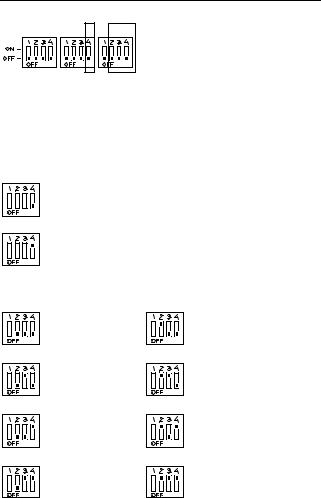
MODBUS PORT SETUP SELECTION
SW1 SW2 SW3
The MODBUS port setup is determined by means of DIP switch 4 on SW2 and DIP switches 2,3 and 4 on SW3. The selectable items are: baudrate and number of stop bits. Parity is not selectable and fixed at “no parity”
SW2-4: Stop Bit Selection
1 stop bit
2 stop bits
SW3-2...4: Baudrate Selection
1200 baud |
2400 baud |
4800 baud |
9600 baud |
19200 baud |
38400 baud |
57600 baud |
115200 baud |
14

GATEWAY SOFTWARE VERSION DISPLAY
SW3-1
When DIP Switch 1 on SW3 is set to the ‘on’ possition the LED indicators (LED 2 to 9) will show the software version:
|
6 |
7 |
8 |
9 |
|
|
2 |
3 |
|
|
|
5 |
4 |
X04 |
#2 #3 |
|
|
#5 |
#4 |
X03 |
Multi485 |
LED#6 LED#7 |
LED#8 LED#9 |
MODBUS |
|||
|
LED LED |
LED |
LED |
|
||
To establish the software version number (01 to 255) add together the ‘value’ associated with each illuminated LED.
LED # |
Value |
6= 1
7= 2
8= 4
9= 8
2= 16
3= 32
5 |
= 64 |
4 |
= 128 |
 Ignore LED 1 (power on indicator), located adjacent to X01; this LED will always be on when power is applied.
For example:
1) LED 6 and 8 = ON; all others off
LED 6 |
= 1 |
LED 8 |
= 4 |
total |
= 5 |
Software Version = ‘E05’ |
|
2) LED 7 and 8 = ON; all others off
LED 7 |
= 2 |
LED 8 |
= 4 |
total |
= 6 |
Software Version = ‘E06’
3) LED 6, 7, 9 and 2 = ON; all others off
LED 6 |
= 1 |
LED 7 |
= 2 |
LED 9 |
= 8 |
LED 2 |
= 16 |
total |
= 27 |
Software Version = ‘E27’
The LED indicators will continue to display the the software version, regardless of operation, until switch 1 on SW3 is set to the ‘off’ possition.
 DIP Switch 1 on SW3 must always be set to the ‘off’ position for normal operation.
 DIP Switch 1 on SW3 has no function with earlier software versions; if the LED indicators continue to operate normally when SW3-1 is switched on, the software is an earlier version; update the software.
Please refer to the table on the following page to assist in decoding the software version number.
15

Decoding The Software Version Number
LED#2 |
LED#3 |
LED#6 |
LED#7 |
LED#8 |
LED#9 |
LED#5 |
LED#4 |
Version |
|
|
|
|
|
|
|
|
|
0 |
0 |
0 |
0 |
0 |
0 |
0 |
0 |
0 |
0 |
0 |
1 |
0 |
0 |
0 |
0 |
0 |
1 |
0 |
0 |
0 |
1 |
0 |
0 |
0 |
0 |
2 |
0 |
0 |
1 |
1 |
0 |
0 |
0 |
0 |
3 |
0 |
0 |
0 |
0 |
1 |
0 |
0 |
0 |
4 |
0 |
0 |
1 |
0 |
1 |
0 |
0 |
0 |
5 |
0 |
0 |
0 |
1 |
1 |
0 |
0 |
0 |
6 |
0 |
0 |
1 |
1 |
1 |
0 |
0 |
0 |
7 |
0 |
0 |
0 |
0 |
0 |
1 |
0 |
0 |
8 |
0 |
0 |
1 |
0 |
0 |
1 |
0 |
0 |
9 |
0 |
0 |
0 |
1 |
0 |
1 |
0 |
0 |
10 |
0 |
0 |
1 |
1 |
0 |
1 |
0 |
0 |
11 |
0 |
0 |
0 |
0 |
1 |
1 |
0 |
0 |
12 |
0 |
0 |
1 |
0 |
1 |
1 |
0 |
0 |
13 |
0 |
0 |
0 |
1 |
1 |
1 |
0 |
0 |
14 |
0 |
0 |
1 |
1 |
1 |
1 |
0 |
0 |
15 |
1 |
0 |
0 |
0 |
0 |
0 |
0 |
0 |
16 |
1 |
0 |
1 |
0 |
0 |
0 |
0 |
0 |
17 |
1 |
0 |
0 |
1 |
0 |
0 |
0 |
0 |
18 |
1 |
0 |
1 |
1 |
0 |
0 |
0 |
0 |
19 |
1 |
0 |
0 |
0 |
1 |
0 |
0 |
0 |
20 |
1 |
0 |
1 |
0 |
1 |
0 |
0 |
0 |
21 |
1 |
0 |
0 |
1 |
1 |
0 |
0 |
0 |
22 |
1 |
0 |
1 |
1 |
1 |
0 |
0 |
0 |
23 |
1 |
0 |
0 |
0 |
0 |
1 |
0 |
0 |
24 |
1 |
0 |
1 |
0 |
0 |
1 |
0 |
0 |
25 |
1 |
0 |
0 |
1 |
0 |
1 |
0 |
0 |
26 |
1 |
0 |
1 |
1 |
0 |
1 |
0 |
0 |
27 |
1 |
0 |
0 |
0 |
1 |
1 |
0 |
0 |
28 |
1 |
0 |
1 |
0 |
1 |
1 |
0 |
0 |
29 |
1 |
0 |
0 |
1 |
1 |
1 |
0 |
0 |
30 |
1 |
0 |
1 |
1 |
1 |
1 |
0 |
0 |
31 |
0 |
0 |
0 |
0 |
0 |
0 |
0 |
0 |
32 |
0 |
0 |
1 |
0 |
0 |
0 |
0 |
0 |
33 |
0 |
0 |
0 |
1 |
0 |
0 |
0 |
0 |
34 |
0 |
0 |
1 |
1 |
0 |
0 |
0 |
0 |
35 |
0 |
0 |
0 |
0 |
1 |
0 |
0 |
0 |
36 |
0 |
0 |
1 |
0 |
1 |
0 |
0 |
0 |
37 |
0 |
0 |
0 |
1 |
1 |
0 |
0 |
0 |
38 |
0 |
0 |
1 |
1 |
1 |
0 |
0 |
0 |
39 |
0 |
0 |
0 |
0 |
0 |
1 |
0 |
0 |
40 |
0 |
0 |
1 |
0 |
0 |
1 |
0 |
0 |
41 |
0 |
0 |
0 |
1 |
0 |
1 |
0 |
0 |
42 |
0 |
0 |
1 |
1 |
0 |
1 |
0 |
0 |
43 |
0 |
0 |
0 |
0 |
1 |
1 |
0 |
0 |
44 |
0 |
0 |
1 |
0 |
1 |
1 |
0 |
0 |
45 |
0 |
0 |
0 |
1 |
1 |
1 |
0 |
0 |
46 |
0 |
0 |
1 |
1 |
1 |
1 |
0 |
0 |
47 |
1 |
1 |
0 |
0 |
0 |
0 |
0 |
0 |
48 |
1 |
1 |
1 |
0 |
0 |
0 |
0 |
0 |
49 |
COMMISSIONING PROCEDURE
1)Before applying power to the X-IRI Gateway ensure:
a)The MODBUS address is set to the correct value (switches 1-4 on SW1 and switches 1- 3 on SW2)
b)The MODBUS port setup matches the MODBUS master’s requirements. Switches 4 on SW2 and switches 2-4 on SW3.
c)The communication link wires from the Gateway to the compressor controller and the MODBUS master are connected, secure and the wire polarities are correct (L1, L2)
2)Apply power to the X-IRI Gateway
3)Ensure communications with the compressor controller is established – ensure indicator (9) is ON permanently.
4)Once the IR-BUS compressor controller communication link is established the MODBUS master unit can start operating. Any attempt from the MODBUS master to communicate before the IR-BUS link is established will simply result in the gateway not responding to the MODBUS master.
5)Once the MODBUS master communicates with the compressor controller through the gateway it should keep on doing so at least once every 10 seconds to keep indicator (6) from flashing.
6)In case the MODBUS master does not communicate at least once every 10 seconds the communication link is considered inactive: indicator
(6) flashes and any earlier commands for the compressor controller to operate in “Host” mode are cancelled => the machine reverts back to local start/stop and load/unload control mode.
16

SECTION 6 - PARTS LIST
X-IRI Communication Gateway
Item Part No. |
Description |
|
- |
23461908 |
KIT, X-IRI Gateway |
- |
80445604 |
Manual, User CD |
- |
23462005 |
DIN Rail, Mounting |
1 |
23461890 |
Module, X-IRI Gateway |
2 |
39266101 |
Module, PSU-24VDC |
3 |
39266135 |
Cable, RJ11 Modbus |
1 |
|
|
2 |
|
|
24VDC |
|
|
DC |
|
|
|
L |
0VDC |
+V.ADJ |
N |
|
|
E |
+24VDC |
100-240VAC |
|
|
50/60Hz |
|
|
N L |
|
|
3
|
|
RJ11 |
L1 (2) |
|
2 |
2 |
1 |
|
|
|
2 |
|
|
|
|
3 |
3 |
|
|
4 |
4 |
4 |
|
|
5 |
5 |
L2 (4) |
M4 |
|
|
|
6 |
||
|
|
|
|
Ring Tag |
SECTION 7 - TECHNICAL DATA
Module, Gateway
Dimensions |
3.8” x 3.4” x 2.2” |
|
96mm x 85mm x 55mm |
Weight |
0.6Ib (0.25kg) |
Mounting |
DIN, 35mm |
Enclosure |
IP20 |
Supply |
24VDC/ac +/-15% |
Power |
1.0VA |
Temperature |
0°C to 46°C (32°F to 115°F) |
Humidity |
95% RH non-condensing |
17

SECTION 8 – INTELLISYS MODBUS TABLES
TABLE 1 SSR (REDEYE) CONTROLLER
Register |
Variable |
Read/Write |
Range |
Notes |
||
(40XXX) |
|
|
|
|
|
|
1 |
Status/Control |
|
|
R/W |
|
See FIGURE 1-1 |
3 |
Discharge Pressure |
|
|
R |
|
|
4 |
Sump Pressure |
|
|
R |
|
|
5 |
Inlet Vacuum |
|
|
R |
|
|
6 |
Coolant Temperature |
|
|
R |
|
|
7 |
Airend Temperature |
|
|
R |
|
|
8 |
Discharge Temperature |
|
|
R |
|
|
9 |
Low Ambient Coolant Temp. |
|
|
R |
|
Low Ambient Option |
64 |
Total Hours (hours) |
|
|
R |
|
|
65 |
Loaded Hours (hours) |
|
|
R |
|
|
96 |
Language Selection |
|
|
R |
|
See FIGURE 1-2 |
97 |
Units of Measure |
|
|
R |
|
See FIGURE 1-2 |
98 |
Rated Pressure |
|
|
R |
|
|
99 |
Rated Horse Power |
|
|
R |
|
See FIGURE 1-2 |
112 |
Offline Pressure |
|
|
R/W |
75 - (rated+3) |
rated = rated pressure |
113 |
Online Pressure |
|
|
R/W |
65-(offline-10) |
offline = offline pressure |
114 |
Display Timer (seconds) |
|
|
R/W |
10-600 |
|
115 |
Star-Delta Time (seconds) |
|
|
R |
|
|
116 |
Auto Start/Stop (AS/S) Time (minutes) |
|
|
R/W |
Feb-60 |
No Write if AS/S is off |
117 |
Auto Start/Stop (AS/S) On/Off |
|
|
R |
0 or 1 |
0=Off, 1=On |
118 |
Sequence Control On/Off |
|
|
R |
0 or 1 |
0=Off, 1=On |
119 |
Remote Start/Stop On/Off |
|
|
R |
0 or 1 |
0=Off, 1=On |
120 |
Mod Only On/Off |
|
|
R/W |
0 or 1 |
0=Off, 1=On |
121 |
Power Out Restart Option (PORO)On/Off |
|
|
R |
0 or 1 |
0=Off, 1=On |
122 |
PORO Time (seconds) |
|
|
R/W |
10-120 |
No Write if PORO is off |
123 |
Load Delay Time (seconds) |
|
|
R/W |
0-60 |
|
124 |
Min. Cooler Out Load Temp |
|
|
R/W |
30-150 |
Low Ambient Option |
125 |
Unloaded Stop Time |
|
|
R/W |
10-30 |
|
255 |
Warning Code |
|
|
R |
|
See FIGURE 1-4 |
256-270 |
Alarm Code History |
|
|
R |
|
See FIGURE 1-4 |
272-286 |
Inlet Vacuum Alarm History |
|
|
R |
|
|
288-302 |
Sump Pressure Alarm History |
|
|
R |
|
|
304-318 |
Discharge Pressure Alarm History |
|
|
R |
|
|
320-334 |
Coolant Temperature Alarm History |
|
|
R |
|
|
336-350 |
Airend Temperature Alarm History |
|
|
R |
|
|
352-366 |
Discharge Temperature Alarm History |
|
|
R |
|
|
368-382 |
Low Ambient Coolant Temp. History |
|
|
R |
|
Low Ambient Option |
384-398 |
Run Hours Alarm History |
|
|
R |
|
|
400-414 |
Load Hours Alarm History |
|
|
R |
|
|
512-526 |
Status Alarm History |
|
|
R |
|
See FIGURE 1-3 |
999 |
IRI Version Number |
|
|
R |
|
Reads from IRI only |
|
|
|
|
|
|
|
18
FIGURE 1-1 |
REGISTER 40001 STATUS / CONTROL |
|||
Bit 0: Host/Local (R/W) |
Bit 6: Alarm (R) |
|||
0 |
= Local |
|
0 |
= No Alarms |
1 |
= Host |
|
1 |
= Alarms |
Bit 1: Run/Stop (R/W) |
Bit 7: Warning (R) |
|||
0 |
= Stop |
|
0 |
= No Warnings |
1 |
= Run |
|
1 |
= Warnings |
Bit 2: Load/Unload (R/W) |
Bit 8: On/Off Line Mode (R) |
|||
0 |
= Unload |
|
0 |
= Not in On/Off Line Mode |
1 |
= Load |
|
1 |
= On/Off Line Mode |
Bit 3: Modulating (R) |
Bit 9: Mod/ACS or Mod Only (R) |
|||
0 |
= Not Modulating |
0 |
= Not in Mod/ASC Mode |
|
1 |
= Modulating |
|
1 |
= Mod/ASC Mode |
Bit 4: Unused |
|
Bits 10-12: Unused |
||
Bit 5: Stopped in Auto Restart (R) |
Bits 13-15: Unit Type (R) |
|||
0 |
= Not Stopped in Auto Restart |
001 = SSR controller |
||
FIGURE 1-2 |
REGISTER CODES |
|
|
Register 096: Language |
Register 097: Units of Measure |
||
0 |
= English |
|
0 = °F and PSI |
1 |
= Spanish |
|
1 = °C and PSI |
2 |
= French |
|
2 = °C and Bar |
3 |
= Portuguese |
|
3 = °C and kPa |
|
|
|
4 = °C and kg/cm2 |
Register 99: Rated Horse Power/Kilowatt |
|||
0 |
= 50hp |
|
7 = 250hp |
1 |
= 60hp |
|
8 = 300hp |
2 |
= 75hp |
|
9 = 350hp |
3 |
= 100hp |
|
10 = 400hp |
4 |
= 125hp |
|
11 = 450hp |
5 |
= 150hp |
|
12 = 500hp |
6 |
= 200hp |
|
|
|
|
|
|
FIGURE 1-3 |
REGISTER STATUS ALARM HISTORY |
||
Bit 0: Run/Stop (R) |
Bit 4: Stopped Auto Restart (R) |
||
0 |
= Stop |
|
0 = Not Stopped in Auto Restart |
1 |
= Run |
|
1= Stopped in Auto Restart |
Bit 1: On/Off Line Mode (R) |
Bit 5: Unused |
||
0 |
= Not in On/Off Line Mode |
|
|
1 |
= On/Off Line Mode |
|
|
Bit 2: MOD/ACS Mode (R) |
Bit 6: Unused |
||
0 |
= Not in Mod/ACS Mode |
|
|
1 |
= Mod/ACS Mode |
|
|
Bit 3: Load/Unload (R) |
Bit 7: Unused |
||
19
FIGURE 1-4 |
REGISTER ALARM / WARNING CODES |
||
|
|
SSR (Redeye) Controller |
|
Code |
Description |
|
|
01 |
Sensor Failure 1AVPT |
|
|
02 |
Sensor Failure 3APT |
|
|
03 |
Sensor Failure 4APT |
|
|
04 |
Sensor Failure P4 (Spare) |
|
|
05 |
Sensor Failure P5 (Spare) |
|
|
06 |
Sensor Failure P6 (Spare) |
|
|
07 |
Sensor Failure P7 (Spare) |
|
|
08 |
Sensor Failure P8 (Spare) |
|
|
09 |
Sensor Failure 2CTT |
|
|
10 |
Sensor Failure 2ATT |
|
|
11 |
Sensor Failure 4ATT |
|
|
12 |
Sensor Failure 3CTT (Optional) |
|
|
13 |
Sensor Failure T5 (Spare) |
|
|
14 |
Sensor Failure T6 (Spare) |
|
|
15 |
Sensor Failure T7 (Spare) |
|
|
16 |
Sensor Failure T8 (Spare) |
|
|
17 |
Starter Fault |
|
|
18 |
Motor Overload (Main) |
|
|
19 |
Fan Motor Overload |
|
|
20 |
Door Open (Starter) |
|
|
21 |
Stepper Limit Switch |
|
|
22 |
Check Motor Rotation |
|
|
23 |
Check Inlet Control System |
|
|
25 |
Remote Stop Failure |
|
|
26 |
Remote Start Failure |
|
|
27 |
Check Inlet Control |
|
|
28 |
Low Unload Sump Pressure |
|
|
29 |
High Air Pressure |
|
|
30 |
Low Sump Air Pressure |
|
|
31 |
High A/E Discharge Temperature |
|
|
32 |
Emergency Stop |
|
|
33 |
Change Inlet Filter |
|
|
34 |
Change Separator Element |
|
|
35 |
Change Coolant Filter |
|
|
36 |
1AVPT Sensor Error (Calibration) |
|
|
37 |
Memory Fault |
|
|
20

TABLE 2 SSR (SG) CONTROLLER
Register |
Variable |
Read/Write |
Range |
Notes |
(40XXX) |
|
|
|
|
1 |
Status/Control |
R/W |
|
See FIGURE 2-1 |
3 |
Discharge Pressure |
R |
|
|
4 |
Sump Pressure |
R |
|
|
5 |
Inlet Vacuum |
R |
|
Divided by 10 |
6 |
Coolant Temperature |
R |
|
|
7 |
Airend Temperature |
R |
|
|
8 |
Discharge Temperature |
R |
|
|
9 |
Low Ambient Coolant Temp. |
R |
|
Low Ambient Option |
10 |
Separator Pressure Drop |
R |
|
|
11 |
Spare Pressure Input 4 |
R |
|
|
12 |
Dry Side Sump Pressure |
R |
|
Spare Pressure Input #5 if no |
|
|
|
|
separator delta-p sensor option |
13 |
Spare Pressure Input 6 |
R |
|
|
14 |
Spare Pressure Input 7 |
R |
|
|
15 |
Remote Pressure |
R |
|
Spare Pressure Input #8 if no |
|
|
|
|
remote sensor option |
16 |
Spare Temperature Input 5 |
R |
|
|
17 |
Spare Temperature Input 6 |
R |
|
|
18 |
Spare Temperature Input 7 |
R |
|
|
19 |
Spare Temperature Input 8 |
R |
|
|
20 |
% Load Modulation |
R |
|
|
64 |
Total Hours (hours) |
R |
0 – 9999 |
Less Than 10000 |
65 |
Loaded Hours (hours) |
R |
0 – 9999 |
Less Than 10000 |
66 |
Ten Thousand Total Hours |
R |
|
Multiply by 10000 |
67 |
Ten Thousand Loaded Hours |
R |
|
Multiply by 10000 |
96 |
Language Selection |
R |
0 – 11 |
See FIGURE 2-2 |
97 |
Units of Measure |
R |
0 – 4 |
See FIGURE 2-2 |
98 |
Rated Pressure |
R |
|
|
99 |
Rated Horse Power/Kilowatt |
R |
0 – 21 |
See FIGURE 2-2 |
100 |
Starter Type |
R |
0 - 4 |
See FIGURE 2-2 |
101 |
Service Level |
R |
0 or 1 |
0=Level 1, 1=Level 2 |
102 |
Service Type |
R |
0 or 1 |
0=Hours, 1=Months |
103 |
Service Interval |
R |
0 - 3 |
3, 6, 9, or 12 months |
112 |
Offline Pressure |
R/W |
75 - (rated+3) |
rated = rated pressure |
113 |
Online Pressure |
R/W |
65-(offline-10) |
offline = offline pressure |
114 |
Mode of Operation |
R/W |
0 – 2 |
See FIGURE 2-2 |
115 |
Star-Delta Time (seconds) |
R |
5 – 20 |
|
116 |
Auto Start/Stop (AS/S) Time (minutes) |
R/W |
2 – 60 |
No Write if AS/S is off |
117 |
Auto Start/Stop (AS/S) On/Off |
R |
0 or 1 |
0=Off, 1=On |
118 |
Sequence Control On/Off |
R |
0 or 1 |
0=Off, 1=On |
119 |
Remote Start/Stop On/Off |
R |
0 or 1 |
0=Off, 1=On |
120 |
Solenoid Delta-P |
R |
0 or 1 |
0=Off, 1=On |
121 |
Power Out Restart Option (PORO)On/Off |
R |
0 or 1 |
0=Off, 1=On |
122 |
PORO Time (seconds) |
R/W |
10 - 120 |
No Write if PORO is off |
123 |
Auto Start/Stop Delay Time (seconds) |
R/W |
0 - 60 |
|
124 |
Min. Cooler Out Load Temp |
R/W |
30 - 150 |
Low Ambient Option |
125 |
Unloaded Stop Time |
R/W |
10-30t |
|
126 |
Low Ambient Option On/Off |
R |
0 or 1 |
0=Off, 1=On |
127 |
Contrast |
R |
0 - 10 |
|
128 |
Lead/Lag |
R/W |
0 or 1 |
0=Off, 1=On |
129 |
Lag Offset |
R/W |
0 - 10 |
|
130 |
Max Modulation Pressure |
R/W |
(Online+10) – |
|
|
|
|
(Offline + 7) |
|
131 |
Lead/Lag Cycle Length (Hours) |
R/W |
0 – 750 |
|
132 |
Scheduled Start (Hour) |
R/W |
0 – 23 |
|
133 |
Scheduled Start (Minute) |
R/W |
0 – 59 |
|
21

134 |
Scheduled Stop (Hour) |
R/W |
0 – 23 |
|
135 |
Scheduled Stop (Minute) |
R/W |
0 – 59 |
|
136 |
Modbus Protocol |
R |
0 or 1 |
0=Off, 1=On |
137 |
Modbus Address |
R |
1 – 247 |
|
138 |
High Dust Filter |
R |
0 or 1 |
0=Off, 1=On |
139 |
Integral Sequencing Lead |
R/W |
0 – 3 |
0=Off, 1=On, 2=Always, 3=Never |
140 |
Integral Sequencing Address |
R/W |
1 – 4 |
|
141 |
Integral Sequencing Total |
R/W |
2 – 4 |
|
142 |
Integral Sequencing Load Delay |
R/W |
10 – 60 |
|
143 |
Integral Sequencing Lead Change (Hours) |
R/W |
0 – 750 |
|
144 |
Integral Sequencing Lead Change – Day |
R/W |
0 – 9 |
See FIGURE 2-2 |
145 |
Integral Sequencing Lead Change – Hour |
R/W |
0 – 23 |
|
146 |
Integral Sequencing Lead Change – Min |
R/W |
0 - 45 |
Steps of 0, 15, 30, 45 |
147 |
Separator Delta-P Sensor |
R |
0 or 1 |
0=Off, 1=On |
148 |
Variable Frequency Drive |
R |
0 or 1 |
0=Off, 1=On |
149 |
Scheduled Start (Day) |
R/W |
0 - 9 |
See FIGURE 2-2 |
150 |
Scheduled Stop (Day) |
R/W |
0 - 9 |
See FIGURE 2-2 |
151 |
Remote Sensor |
R |
0 or 1 |
0=Off, 1=On |
250 |
Options |
R |
|
See FIGURE 2-2 |
251 |
Unloaded Inlet Vacuum |
R |
|
|
252 |
Software Part Number – Most Significant |
R |
|
High Digits |
253 |
Software Part Number – Least Significant |
R |
|
Low Digits |
254 |
Software Version Number |
R |
|
|
255 |
Warning Code |
R |
|
See FIGURE 2-4 |
256-270 |
Alarm Code History |
R |
|
See FIGURE 2-4 |
272-286 |
Inlet Vacuum Alarm History |
R |
|
|
288-302 |
Sump Pressure Alarm History |
R |
|
|
304-318 |
Discharge Pressure Alarm History |
R |
|
|
320-334 |
Coolant Temperature Alarm History |
R |
|
|
336-350 |
Airend Temperature Alarm History |
R |
|
|
352-366 |
Discharge Temperature Alarm History |
R |
|
|
368-382 |
Low Ambient Coolant Temp. History |
R |
|
Low Ambient Option |
384-398 |
Total Hours Alarm History |
R |
|
Less Than 10000 Hours |
400-414 |
10000 Total Hours Alarm History |
R |
|
Multiply by 10000 |
416-430 |
Loaded Hours Alarm History |
R |
|
Less Than 10000 Hours |
432-446 |
10000 Loaded Hours Alarm History |
R |
|
Multiply by 10000 |
448-462 |
Unloaded Inlet Vacuum Alarm History |
R |
|
|
464-478 |
Coolant Pressure Alarm History |
R |
|
|
480-494 |
Dry Side Sump Pressure Alarm History |
R |
|
|
496-510 |
Remote Pressure Alarm History |
R |
|
|
512-526 |
Status Alarm History |
R |
|
See FIGURE 2-3 |
528-542 |
Real Time Clock Alarm History – Hours |
R |
|
|
544-558 |
Real Time Clock Alarm History – Minutes |
R |
|
|
560-574 |
Real Time Clock Alarm History – Month |
R |
|
|
576-590 |
Real Time Clock Alarm History – Date |
R |
|
|
592-606 |
Real Time Clock Alarm History – Year |
R |
|
|
999 |
IRI Version Number |
R |
|
Reads from IRI only |
|
|
|
|
|
22
FIGURE 2-1 |
REGISTER 40001 STATUS / CONTROL |
|||
Bit 0: Host/Local (R/W) |
Bit 6: Alarm (R) |
|||
0 |
= Local |
|
0 |
= No Alarms |
1 |
= Host |
|
1 |
= Alarms |
Bit 1: Run/Stop (R/W) |
Bit 7: Warning (R) |
|||
0 |
= Stop |
|
0 |
= No Warnings |
1 |
= Run |
|
1 |
= Warnings |
Bit 2: Load/Unload (R/W) |
Bit 8: On/Off Line Mode (R) |
|||
0 |
= Unload |
|
0 |
= Not in On/Off Line Mode |
1 |
= Load |
|
1 |
= On/Off Line Mode |
Bit 3: Modulating (R) |
Bit 9: Mod/ACS or Mod Only (R) |
|||
0 |
= Not Modulating |
0 |
= Not in Mod/ASC Mode |
|
1 |
= Modulating |
|
1 |
= Mod/ASC Mode |
Bit 4: Unused |
|
Bits 10-12: Unused |
||
Bit 5: Stopped in Auto Restart (R) |
Bits 13-15: Unit Type (R) |
|||
0 |
= Not Stopped in Auto Restart |
001 = SSR controller |
||
1 |
= Stopped in Auto Restart |
|
|
|
23

|
FIGURE 2-2 |
REGISTER CODES |
|
|
|
|
|
|
|
||||
|
Register 096: Language |
Register 097: Units of Measure |
|
|||
0 |
= English |
|
0 |
= °F and PSI |
||
1 |
= Spanish |
|
1 |
= °C and PSI |
||
2 |
= Portuguese |
|
2 |
= °C and Bar |
||
3 |
= French |
|
3 |
= °C and kPa |
||
4 |
= Italian |
|
4 |
= °C and kg/cm2 |
||
5 |
= Dutch |
|
|
|
|
|
6 |
= German |
|
|
|
|
|
7 |
= Danish |
|
|
|
|
|
8 |
= Norwegian |
|
|
|
|
|
9 |
= Swedish |
|
|
|
|
|
|
10 = Finnish |
|
|
|
|
|
|
11 = Turkish |
|
|
|
|
|
Register 99: Rated Horse Power/Kilowatt |
Register 100: Starter Type |
||||
0 |
= 50hp |
11 |
= 450hp |
0 = Star-Delta |
|
1 |
= 60hp |
12 |
= 500hp |
1 = Full Voltage |
|
2 |
= 75hp |
13 |
= 75kw |
2 = Remote Star-Delta |
|
3 |
= 100hp |
14 |
= 90kw |
3 = Remote Full Voltage |
|
4 |
= 125hp |
15 |
= 110kw |
4 = Soft Starter |
|
5 |
= 150hp |
16 |
= 132kw |
|
|
6 |
= 200hp |
17 |
= 150kw |
|
|
7 |
= 250hp |
18 |
= 200kw |
|
|
8 |
= 300hp |
19 |
= 250kw |
|
|
9 |
= 350hp |
20 |
=300kw |
|
|
10 = 400hp |
21 |
= 250kw |
|
|
|
Register 114: Mode of Operation |
Register 144: Integral Sequencing Lead Change - Day |
||||
0 |
= MOD/ACS |
|
|
Register 149: Schedule Start - Day |
|
1 |
= On/Off Line |
|
|
Register 150: Schedule Stop - Day |
|
2 |
= Modulation Only |
|
|
0= Sunday |
|
|
|
|
|
1 |
= Monday |
|
|
|
|
2 |
= Tuesday |
|
|
|
|
3 |
= Wednesday |
|
|
|
|
4 |
= Thursday |
|
|
|
|
5 |
= Friday |
|
|
|
|
6 |
= Saturday |
|
|
|
|
7 |
= Daily |
|
|
|
|
8 |
= Weekdays |
|
|
|
|
9 |
= Weekends |
Register 250: Options
Bit 0: Power Out Restart and Scheduled Start/Stop
0 = Off
1 = On
FIGURE 2-3 |
REGISTER STATUS ALARM HISTORY |
||
Bit 0: Run/Stop (R) |
Bit 4: Stopped Auto Restart (R) |
||
0 |
= Stop |
|
0 = Not Stopped in Auto Restart |
1 |
= Run |
|
1 = Stopped in Auto Restart |
Bit 1: On/Off Line Mode (R) |
Bit 5: Unused |
||
0 |
= Not in On/Off Line Mode |
|
|
1 |
= On/Off Line Mode |
|
|
Bit 2: MOD/ACS Mode (R) |
Bit 6: Unused |
||
0 |
= Not Modulating |
|
|
1 |
= Modulating |
|
|
Bit 3: Load/Unload (R) |
Bit 7: Unused |
||
0 |
= Unload |
|
|
1 |
= Load |
|
|
24
 Loading...