


285B
Table of contents
 Loading...
Air Impact W rench
Series 285B, 295A, 431L
Product Information
80160666
Edition 5
November 2005
EN
Product Information
ES
Especificaciones del producto
FR
Spécifications du produit
IT
Specifiche prodotto
DE
Technische Produktdaten
NL
Productspecificaties
DA
Produktspecifikationer
SV
Produktspecifikationer
NO
Produktspesifikasjoner
FI
Tuote-erittely
PT
Especificações do Produto
EL
Προδιαγραφές προϊόντος
Save These Instructions
SL
Specifikacije izdelka
SK
Špecifikácie produktu
CS
Specifikace výrobku
ET
Toote spetsifikatsioon
HU
A termék jellemzői
LT
Gaminio techniniai duomenys
LV
Ierices specifikacijas
PL
Dane techniczne narzędzia
Rozmiar
RU
Технические характеристики
изделия
ZH
产品信息
JA
製品仕様
KO
제품 상세
10
11
48h
(Dwg. 04581666)
48h
3
9
48h
11
48h
PMAX
6
4
8
7
9
2
1
24h
5
3
1
2
I-R # - NPT I-R # - BS inch (mm) NPT I-R # I-R # I-R #
C241-810 C28241-810-B 3/4 (19) 1/2 MSCF44 10 100-1lb 4 100-1lb 4
6 7
5
9
10
11
3
I-R #
cm
cm
1 80160666_ed5
3

EN
Product Safety Information
Intended Use:
These Air Impact Wrenches are designed to remove and install threaded fasteners.
For additional information refer to Impact Wrenches Product Safety Information Manual Form
04580916.
Manuals can be downloaded from www.irtools.com.
Product Specifications
Model(s) Style
Inside
285B
Trigger
Inside
285B-6
Trigger
Inside
285B-S-6
Trigger
Pistol
295A
Grip
Pistol
295A-6
Grip
Outside
431L
Trigger
Impacts
per
min.
Recomme-
nded Torque
(136-1220)
(136-1220)
(136-1220)
(136-1220)
(136-1220)
(136-1220)
Drive
Type Size ft-lbs (Nm)
Square 1” 700
Square
6" extended
6" extended
6" extended
6" extended
1” 700
Spline
#5 700
Square 1” 700
Square
1” 700
Square
1" 700
Range
100-900
100-900
100-900
100-900
100-900
100-900
Sound Level dB(A)
(ISO 15744)
Power (L
)
Pressure (L
p
”=3dB(A)
“K
pA
“K
wA
102.5 113.5 6.0
102.5 113.5 5.7
102.5 113.5 5.7
103.1 114.1 5.0
103.1 114.1 7.5
102.5 113.5 5.7
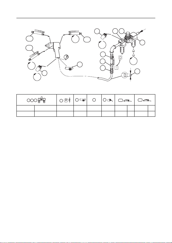
Installation and Lubrication
Size air supply line to ensure tool's maximum operating pressure (PMAX) at tool inlet. Drain condensate from
valve(s) at low point(s) of piping, air filter and compressor tank daily. Install a properly sized Safety Air Fuse
upstream of hose and use an anti-whip device across any hose coupling without internal shut-off, to prevent
hose whipping if a hose fails or coupling disconnects. See drawing 04581666 and table on page 2.
Maintenance frequency is shown in circular arrow and defined as h=hours, d=days, and m=months. Items
identified as:
1. Air filter 7. C oupling
2. Regulator 8. Safety Air Fuse
3. Lubricator 9. Oil
4. Emergency shut-off valve 10. Grease - during assembly
5. Hose diameter 11. Grease - through fitting
6. Thread size
Parts and Maintenance
When the life of the tool has expired, it is recommended that the tool be disassembled, degreased and parts
be separated by material so that they can be recycled.
The original language of this manual is English.
Tool repair and maintenance should only be carried out by an authorized Service Center.
Refer all communications to the nearest Ingersoll-Rand Office or Distributor.
w
”=3dB(A)
)
Vibration
Level
(ISO 8662)
m/s²
80160666_ed5 EN-1

ES
Información de seguridad sobre el producto
Uso indicado:
Los aprietatuercas neumáticos de percusión están diseñados para extraer e instalar fiadores
roscados.
Para más información, consulte el Manual de información de seguridad de producto 04580916
Aprietatuercas neumático de percusión.
Los manuales pueden descargarse en www.irtools.com.
Especificaciones
Modelo Tipo
285B
285B-6
285B-S-6
295A Pistola Cuadrado 1” 700
295A-6 Pistola
431L
Tracción
Tipo Tamaño ft-lb (Nm)
Gatillo
Cuadrado 1” 700
interior
Gatillo
interior
Gatillo
interior
Gatillo
exterior
Cuadrado
6” ampliado
Ranura 6”
ampliada
Cuadrado
6” ampliado
Cuadrado
6” ampliado
1” 700
#5 700
1” 700
1” 700
Impactos
por
minuto
Intervalo de par
recomendado
100-900
(136-1220)
100-900
(136-1220)
100-900
(136-1220)
100-900
(136-1220)
100-900
(136-1220)
100-900
(136-1220)
Nivel sonoro dB (A)
(ISO 15744)
)
Presión (L
“KpA”=3dB(A)
Potencia (Lw)
p
“KwA”=3dB(A)
102.5 113.5 6.0
102.5 113.5 5.7
102.5 113.5 5.7
103.1 114.1 5.0
103.1 114.1 7.5
102.5 113.5 5.7
Instalación y lubricación
Diseñe la línea de suministro de aire para asegurar la máxima presión de funcionamiento (PMAX) en la
entrada de la herramienta. Vacíe el condensado de las válvulas en los puntos inferiores de la tubería, filtro de
aire y depósito del compresor de forma diaria. Instale una contracorriente de manguera de fusil de aire de
seguridad de tamaño adecuado y utilice un dispositivo antilatigazos en cualquier acoplamiento de manguera
sin apagador interno para evitar que las mangueras den latigazos en caso de que una manguera falle o de
que el acoplamiento se desconecte. Consulte la dibujo 04581666 y la tabla en la página 2.
La frecuencia de mantenimiento se muestra en forma de flecha circular y se define como h=horas, d=días y
m=meses. Los elementos se identifican como:
1. Filtro de aire 7. Acoplamiento
2. Regulador 8. Fusil de aire de seguridad
3. Lubricador 9. Aceite
4. Válvula de corte de emergencia 10. Grasa - durante el montaje
5. Diámetro de la manguera 11. Grasa - por el engrasador
6. Tamaño de la rosca
Piezas y mantenimiento
Una vez vencida la vida útil de herramienta, se recomienda desarmar la herramienta, desengrasarla y separar
las piezas de acuerdo con el material del que están fabricadas para reciclarlas.
El idioma original de este manual es el inglés.
Las labores de reparación y mantenimiento de las herramientas sólo puede ser realizadas por un Centro de
Servicio Autorizado.
Toda comunicación se deberá dirigir a la oficina o al distribuidor Ingersoll-Rand más próximo.
ES-1 80160666_ed5
Nivel de
vibración
(ISO 8662)
m/s²

FR
Informations de sécurité du produit
Utilisation prévue:
Ces clés pneumatiques à chocs sont conçues pour le vissage/dévissage de dispositifs de fixation
filetés.
Pour des informations complémentaires, utilisez le formulaire 04580916 pour obtenir le manuel
d'information de sécurité du produit Clé pneumatique à chocs.
Les manuels peuvent être téléchargés à l'adresse www.irtools.com.
Spécifications du produit
Modèle(s) Burin
Gâchette
285B
intérieure
Gâchette
285B-6
intérieure
Gâchette
285B-S-6
intérieure
295A Pistolet Engrenage 1” 700
295A-6 Pistolet
Gâchette
431L
extérieure
Conduit
Type Taille ft-lb (Nm)
Engrenage 1” 700
6” Extension
d'engrenage
6” Extension
de cannelure
6” Extension
d'engrenage
6” Extension
d'engrenage
1” 700
#5 700
1” 700
1” 700
Impacts
par
minutes
Gamme de
couples
recommandée
100-900
(136-1220)
100-900
(136-1220)
100-900
(136-1220)
100-900
(136-1220)
100-900
(136-1220)
100-900
(136-1220)
Niveau acoustique dB (A )
(ISO 15744)
)
Pression (L
“KpA”=3dB(A)
Puissance (Lw)
p
“KwA”=3dB(A)
102.5 113.5 6.0
102.5 113.5 5.7
102.5 113.5 5.7
103.1 114.1 5.0
103.1 114.1 7.5
102.5 113.5 5.7
Installation et lubrification
Dimensionnez l'alimentation en air de façon à obtenir une pression maximale (PMAX) au niveau de l'entrée
d'air de l'outil. Drainez quotidiennement le condensat des vannes situées aux points bas de la tuyauterie, du
filtre à air et du réservoir du compresseur. Installez un raccordement à air de sûreté dont la taille est adaptée
au tuyau et placez-le en amont de celui-ci, puis utilisez un dispositif anti-débattement sur tous les raccords
pour tuyaux sans fermeture interne, afin d'empêcher les tuyaux de fouetter si l'un d'entre eux se décroche ou
si le raccord se détache. Reportez-vous à l'illustration 04581666 et au tableau de la page 2.
Les intervalles d'entretien sont indiqués à l'aide d'une flèche circulaire et définis à l'aide de lettres (h = heures,
d = jours et m =mois). Eléments identifiés en tant que:
1. Filtre à air 7. Raccord
2. Régulateur 8. Raccordement à air de sûreté
3. Lubrificateur 9. Huile
4. Vanne d'arrêt d'urgence 10. Graisse - pour l'assemblage
5. Diamètre du tuyau 11. Graisse - pour le raccordement
6. Taille du filetage
Pièces détachées et maintenance
A la fin de sa durée de vie, il est recommandé de démonter l'outil, de dégraisser les pièces et de les séparer
en fonction des matériaux de manière à ce que ces derniers puissent être recyclés.
Ce manuel a été initialement rédigé en anglais.
La réparation et la maintenance des outils ne devraient être réalisées que par un centre de services autorisé.
Adressez toutes vos communications au Bureau Ingersoll-Rand ou distributeur le plus proche.
Niveau de
vibration
(ISO 8662)
m/s²
80160666_ed5 FR-1

IT
Informazioni sulla sicurezza del prodotto
Destinazione d'uso:
Gli avvitatori pneumatici a impulsi sono adatti per operazioni di estrazione e installazione di
dispositivi di fissaggio filettati.
Per ulteriori informazioni, consultare il modulo 04580916 del Manuale informazioni sulla sicurezza
prodotto relativo agli avvitatori pneumatici a impulsi.
I manuali possono essere scaricati da internet al sito www.irtools.com.
Specifiche prodotto
Modello/i Stile
Grilletto
285B
interno
Grilletto
285B-6
interno
Grilletto
285B-S-6
interno
Impugn
295A
atura
Impugn
295A-6
atura
Grilletto
431L
esterno
Azionamento
Tipo Dimensioni ft-lb (Nm)
Quadro 1” 700
Albero 6”
prolungato
Scanalatura
6” prolungata
Quadro 1” 700
Albero 6”
prolungato
Albero 6”
prolungato
Impulsi
minuto
1” 700
#5 700
1” 700
1” 700
al
Intervallo
coppie
consigliato
100-900
(136-1220)
100-900
(136-1220)
100-900
(136-1220)
100-900
(136-1220)
100-900
(136-1220)
100-900
(136-1220)
Livello acustico dB (A)
(ISO 15744)
)
Pressione (L
“KpA”=3dB(A)
Potenza (Lw)
p
“KwA”=3dB(A)
102.5 113.5 6.0
102.5 113.5 5.7
102.5 113.5 5.7
103.1 114.1 5.0
103.1 114.1 7.5
102.5 113.5 5.7
Installazione e lubrificazione
La linea di alimentazione dell'aria deve essere dimensionata in maniera tale da assicurare all'utensile la
massima pressione di esercizio (PMAX) in ingresso. Scaricare quotidianamente la condensa dalla valvola o
dalle valvole sulla parte bassa della tubatura, dal filtro dell'aria e dal serbatoio del compressore. Installare un
fusibile di sicurezza di dimensioni adatte a monte del tubo flessibile e utilizzare un dispositivo antivibrazioni su
tutti i manicotti senza arresto interno per evitare i colpi di frusta dei flessibili, se questi si guastano o se si
staccano gli accoppiamenti. Vedere il disegno 04581666 e la tabella a pagina 2.
La frequenza delle operazioni di manutenzione è indicata da una freccia circolare ed è espressa in h=ore,
d=giorni e m=mesi. Componenti:
1. Filtro aria 7. Accoppiamento
2. Regolatore 8. Fusibile di sicurezza
3. Lubrificatore 9. Olio
4. Valvola di arresto di emergenza 10. Ingrassaggio - durante il montaggio
5. Diametro tubo flessibi le 11. Ingrassaggio - attraverso il raccordo
6. Dimensione della filettatura
Ricambi e manutenzione
Quando l’attrezzo diventato inutilizzabile, si raccomanda di smontarlo, sgrassarlo e separare i componenti
secondo i materiali in modo da poterli riciclare.
La lingua originale di questo manuale è l'inglese.
Riparazioni e manutenzione degli utensili devono essere eseguite esclusivamente da un Centro di Assistenza
Autorizzato.
Indirizzare tutte le comunicazioni al più vicino concessionario od ufficio Ingersoll-Rand.
IT-1 80160666_ed5
Vibrazioni
Livello
(ISO 8662)
m/s²

DE
Hinweise zur Produktsicherheit
Vorgesehene Verwendung:
Druckluft-Schlagschrauber sind für das Einschrauben und Lösen von Befestigungselementen mit
Gewinden vorgesehen.
Weitere Informationen entnehmen Sie dem Produktsicherheits-Handbuch für den DruckluftSchlagbohrer 04580916.
Handbücher können von www.irtools.com heruntergeladen werden.
Technische Produktdaten
Modell(e) Machart
Auslöser
285B
innen
Auslöser
285B-6
innen
Auslöser
285B-S-6
innen
295A Pistole
295A-6 Pistole
Auslöser
431L
außen
Antrieb
Typ
Quadratischer
Ausgangsantrieb
6” Vergrößerter
quadratischer
Ausgangsantrieb
6” Vergrößerter
keilverzahnter
Ausgangsantrieb
Quadratischer
Ausgangsantrieb
6” Vergrößerter
quadratischer
Ausgangsantrieb
6” Vergrößerter
quadratischer
Ausgangsantrieb
Größe
1” 700
1” 700
# 5 700
1” 700
1” 700
1” 700
Schläge
pro
Minute
Empfohlener
Drehmomen-
tbereich
ft-lb (Nm)
100-900
(136-1220)
100-900
(136-1220)
100-900
(136-1220)
100-900
(136-1220)
100-900
(136-1220)
100-900
(136-1220)
Schallpegel dB (A)
(ISO 15744)
Druck (L
)
Stromzufuhr (Lw)
p
“KpA”=3dB(A)
“KwA”=3dB(A)
102.5 113.5 6.0
102.5 113.5 5.7
102.5 113.5 5.7
103.1 114.1 5.0
103.1 114.1 7.5
102.5 113.5 5.7
Montage und Schmierung
Druckluftzufuhrleitung an der Druckluftzufuhr des Werkzeugs gemäß des maximalen Betriebsdrucks (PMAX)
bemessen. Kondensat an den Ventilen an Tiefpunkten von Leitungen, Luftfilter und Kompressortank täglich
ablassen. Eine Sicherheits-Druckluftsicherung gegen die Strömungsrichtung im Schlauch und eine
Anti-Schlagvorrichtung an jeder Verbindung ohne interne Sperre installieren, um ein Peitschen des Schlauchs
zu verhindern, wenn ein Schlauch fehlerhaft ist oder sich eine Verbindung löst. Siehe Zeichnung 04581666
und Tabelle auf Seite 2.
Die Wartungsfrequenz ist in dem kreisförmigen Pfeil als h=Stunden, d=Tage und m=Monate angegeben. T eile:
1. Luftfilter 7. Verbindung
2. Regler 8. Sicherheits-Druckluftsicherung
3. Schmierbüchse 9 Ölen
4. Notabsperrventil 10. Fetten - bei der Montage
5. Schlauchdurchmesser 11. Fetten - über Anschlussstück
6. Gewindegröße
Teile und Wartung
Zur Entsorgung ist das Werkzeug vollständig zu demontieren, zu entfetten und nach Materialarten getrennt
der Wiederverwertung zuzuführen.
Die Originalsprache dieses Handbuchs ist Englisch.
Die Werkzeug-Reparatur und -Wartung darf nur von einem autorisierten Wartungszentrum durchgeführt werden.
Wenden Sie sich bei Rückfragen an Ihre nächste
Fachhandel.
80160666_ed5 DE-1
Ingersoll-Rand
Niederlassung oder den autorisierten
Schwingungs
intensität
(ISO 8662)
2
m/s

NL
Productveiligheidsinformatie
Bedoeld gebruik:
Deze pneumatische slagmoersleutels zijn bedoeld om schroefdraadbevestigingen te verwijderen en
te plaatsen.
Raadpleeg formulier 04580916 in de productveiligheidshandleiding van de pneumatische
slagmoersleutels voor aanvullende informatie.
Handleidingen kunnen worden gedownload vanaf www.irtools.com.
Produktspesifikasjoner
Model(len) Soort
285B
285B-6
285B-S-6
295A Pistool Haaks 1” 700
295A-6 Pistool
431L
Aandrijving
Type Afmeting ft-lb (Nm)
Pal
Haaks 1” 700
binnen
Pal
binnen
Pal
binnen
Pal
buiten
Haaks
6” verlengd
Wig 6”
verlengd
Haaks
6” verlengd
Haaks
6” verlengd
1” 700
#5 700
1” 700
1” 700
Slagen
per
minuut
Aanbevolen
bereik koppel
100-900
(136-1220)
100-900
(136-1220)
100-900
(136-1220)
100-900
(136-1220)
100-900
(136-1220)
100-900
(136-1220)
Geluidsniveau dB (A)
(ISO 15744)
)
Vermogen (Lw)
Druk (L
p
“KpA”=3dB(A)
“KwA”=3dB(A)
102.5 113.5 6.0
102.5 113.5 5.7
102.5 113.5 5.7
103.1 114.1 5.0
103.1 114.1 7.5
102.5 113.5 5.7
Installatie en smering
Om de maximale bedrijfsdruk ( Pmax) bij de luchtinlaat van het toestel te garanderen, moet de
luchttoevoerleiding hierop geselecteerd zijn. Tap dagelijks condensaat af van kleppen bij lage punten van het
leidingwerk, de luchtfilter en de compressortank. Monteer een beveiliging met de juiste afmeting
bovenstrooms van de slang en gebruik een antislingerinrichting op elke slangkoppeling zonder interne
afsluiter om te voorkomen dat de slang gaat slingeren als een slang valt of een koppeling losraakt. Zie
tekening 04581666 en tabel op pagina 2.
Frequentie voor onderhoud staat aangegeven in ronde pijl en is gedefinieerd als h=uren, d=dagen en
m=maanden. Aangegeven onderdelen:
1. Luchtfilter 7. Koppeling
2. Regelaar 8. Beveiliging
3. Smeerinrichting 9. Olie
4. Noodafsluitklep 10. Smeervet - tijdens montage
5. Slangdiameter 11. Smeervet - door smeernippel
6. Soort van schroefdraad
Onderdelen en onderhoud
Wanneer de levensduur van het gereedschap verstreken is, wordt u aangeraden het gereedschap te demonteren
en ontvetten, en de delen gescheiden naar materialen op te bergen zodat zij gerecycled kunnen worden.
De oorspronkelijke taal van deze handleiding is Engels.
Reparatie en onderhoud van dit gereedschap mogen uitsluitend door een erkend servicecentrum worden
uitgevoerd.
Richt al uw communicatie tot het dichtsbijzijnde Ingersoll-Rand Kantoor ofWederkoper.
NL-1 80160666_ed5
Trillings-
niveau
(ISO 8662)
m/s²

DA
Produktsikkerhedsinformation
Anvendelsesområder:
Trykmomentnøgler er udformet til at fjerne og installere gevindskårne lukkemekanismer.
For yderligere information henvises der til produktsikkerhedsinformationen til Trykluftsnøglen i
vejledning 04580916.
Vejledningerne kan hentes ned fra www.irtools.com.
Specifikationer
Effekt (Lw)
Vibrations
niveau
(ISO 8662)
m/s²
Model (ler) Stil
Indvendig
285B
Indløser
Indvendig
285B-6
Indløser
Indvendig
285B-S-6
Indløser
295A Pistol Kvadrat 1” 700
295A-6 Pistol
Udvendig
431L
udløser
Drev
Type Størrelse ft-lb (Nm)
Kvadrat 1” 700
Kvadrat
Not 6”
Kvadrat
Kvadrat
1” 700
#5 700
1” 700
1” 700
6” forlænget
forlænget
6” forlænget
6” forlænget
Slag
pr.
minut
Anbefalet
momentområde
100-900
(136-1220)
100-900
(136-1220)
100-900
(136-1220)
100-900
(136-1220)
100-900
(136-1220)
100-900
(136-1220)
Lydniveau dB (A)
(ISO 15744)
Tryk (L
)
p
“KpA”=3dB(A)
“KwA”=3dB(A)
102.5 113.5 6.0
102.5 113.5 5.7
102.5 113.5 5.7
103.1 114.1 5.0
103.1 114.1 7.5
102.5 113.5 5.7
Installation og smøring
Sørg for at lufttilførselsledningen har den korrekte størrelse for at sikre maksimalt driftstryk (PMAX) ved
værktøjsindgangen. Tøm dagligt ventilen(-erne) for kondensat ved rørenes, luftfilterets og kompressortankens
lavpunkt(er). Montér en sikkerhedstryksikring i korrekt størrelse i opadgående slange og brug en antipiskeanordning tværs over enhver slangekobling uden intern aflukning for at forhindre at slangen pisker, hvis
en slange svigter eller kobling adskilles. Se tegning 04581666 og tabel på side 2.
Vedligeholdelsesfrekvensen vises i en cirkulær pil og defineres som t=timer, d=dage og m=måneder.
Elementerne er identificeret som:
1. Luftfilter 7. Kobling
2. Regulator 8. Sikkerhedstryksikring
3. Smøreapparat 9. Olie
4. Nødafspærringsventil 10. Fedt - under samlingen
5. Slangediameter 11. Fedt - gennem monteringen
6. Gevindstørrelse
Reservedele og vedligeholdelse
Efter værktøjets levetid anbefales det at demontere og affedte værktøjet, og opdele de adskilte komponenter
ud fra materialetypen, så de kan genbruges.
Denne vejlednings originalsprog er engelsk.
Reparationsarbejde og vedligeholdelse må kun udføres af et autoriseret servicecenter.
Al korrespondance bedes stilet til Ingersoll-Rands nærmeste kontor eller distributør.
80160666_ed5 DA-1

SV
Produktsäkerhetsinformation
Avsedd användning:
Dessa luftdrivna slående muttermaskiner är utformade för att lossa och dra åt gängade fästelement.
För mer information, se Luftdrivna slående muttermaskiners produktsäkerhetsinformation Form
04580916.
Handböcker kan laddas ner från www.irtools.com.
Produktspecifikationer
Effekt (Lw)
Vibrations
nivå
(ISO 8662)
m/s²
Modell(er) Typ
Invändig
285B
avtryckare
Invändig
285B-6
avtryckare
Invändig
285B-S-6
avtryckare
295A Pistol Fyrkant 1” 700
295A-6 Pistol
Utvändig
431L
avtryckare
Drivning
Typ Storlek ft-lb (Nm)
Fyrkant 1” 700
6” Utdragen
6” Utdragen
6” Utdragen
6” Utdragen
fyrkant
spline
fyrkant
fyrkant
1” 700
#5 700
1” 700
1” 700
Slag
per
minut
Rekommenderat
momentområde
100-900
(136-1220)
100-900
(136-1220)
100-900
(136-1220)
100-900
(136-1220)
100-900
(136-1220)
100-900
(136-1220)
Ljudstyrkenivå dB (A)
(ISO 15744)
Tryck (L
)
p
“KpA”=3dB(A)
“KwA”=3dB(A)
102.5 113.5 6.0
102.5 113.5 5.7
102.5 113.5 5.7
103.1 114.1 5.0
103.1 114.1 7.5
102.5 113.5 5.7
Installation och smörjning
Dimensionera luftledningen för att säkerställa maximalt driftstryck (PMAX) vid verktygets ingångsanslutning.
Dränera dagligen kondens från ventiler placerade vid ledningens lägsta punkter, luftfilter och kompressortank.
Installera en säkerhetsventil av lämplig storlek uppström från slangen och använd en anti-ryckenhet över alla
slangkopplingar som saknar intern avstängning, för att motverka att slangen rycker till och en slang går
sönder eller koppling lossar. Se illustrationen 04581666 och tabellen på sidan 2.
Underhållsfrekvensen visas i cirkelpilar och definieras som h=timmar, d=dagar och m=månader. Posterna
definieras som:
1. Luftfilter 7. Koppling
2. Regulator 8. Säkerhetsventil
3. Smörjare 9. Olja
4. Nödstoppsventil 10. Fett – under montering
5. Slangdiameter 11. Fett - via anslutning
6. Gängdimension
Delar och underhåll
Då verktyget är utslitet, rekommenderar vi att det tas isär och avfettas, samt att de olika delarna sorteras för
återvinning.
Det ursprungliga språket för den här handboken är engelska.
Reparation och underhåll av verktygen får endast utföras av ett auktoriserat servicecenter.
Alla förfrågningar bör ske till närmaste Ingersoll-Rand kontor eller distributör.
SV-1 80160666_ed5
Loading...