


 Loading...
112213.16.20
24519472
Revision B October 2013
Compressor Control System
Model Xe- 145M SSR |
PRINT LANGUAGE |
|
|
|
|
ENGLISH |
GREEK |
RUSSIAN |
|
|
|
|
|
|
|
|
|
|
|
|
BULGARIAN |
HUNGARIAN |
SLOVAKIAN |
|
|
|
|
|
|
|
|
|
|
|
|
CZECH |
ITALIAN |
SLOVENIAN |
|
|
|
|
|
|
|
|
|
|
|
|
DANISH |
LITHUANIAN |
SPANISH |
|
|
|
|
|
|
|
|
|
|
|
|
DUTCH |
LATVIAN |
SWEDISH |
|
|
|
|
|
|
|
|
|
|
|
|
ESTONIAN |
NORWEGIAN |
TURKISH |
|
|
|
|
|
|
|
FINNISH |
POLISH |
CHINESE |
|
|
|
|
|
|
|
FRENCH |
PORTUGUESE |
|
|
|
|
|
|
|
|
|
|
|
|
|
GERMAN |
ROMANIAN |
|
|
|
|
|
|
|
|
|
|
|
|
Instruction Manual
EN BG CS DA NL ET FI FR DE EL HU IT
LV
Instruction Manual |
LT |
Instrukcijų vadovas |
Ръководство за употреба |
NO |
Instruksjonsmanual |
Návod k obsluze |
PL |
Instrukcja obsługi |
Instruktionsmanual |
PT |
Manual de Instruções |
Instructiehandleiding |
RO |
Manual de utilizare |
Kasutusjuhend |
RU |
Инструкция по эксплуатации |
Käyttöopas |
SK |
Návod na použitie |
Manuel d’instructions |
SL |
Priročnik z navodili |
Anleitungshandbuch |
ES |
Manual de instrucciones |
Εγχειρίδιο Οδηγιών |
SV |
Instruktionsmanual |
Kezelői kézikönyv |
TU |
Kullanım Kılavuzu |
Manuale di istruzioni |
ZH |
|
Ekspluatācijas rokasgrāmata |
|
|
Save These Instructions

112213.16.20
EN
Contents
SAFETY INFORMATION.. . . . . . . . . . . . . . . . . . . . . . . . . . . . . . . . 4
EXPLANATION OF SAFETY SIGNAL WORDS. . . . . . . . . . . . . . . 4 GENERAL WORKPLACE SAFETY. . . . . . . . . . . . . . 4 DOCUMENTATION, DECALS & TAGS. . . . . . . . . . . . 4 PERSONAL PROTECTIVE EQUIPMENT & ATTIRE. . . . . . 4 OPERATION. . . . . . . . . . . . . . . . . . . . . . . 4 SERVICE, MAINTENANCE, AND REPAIR. . . . . . . . . . 5
INTERFACE DATA & KEYS. . . . . . . . . . . . . . . . . . . . . . . . . . . . . . . 6
Xe-145M. . . . . . . . . . . . . . . . . . . . . . . . . 6 LED STATUS ICONS. . . . . . . . . . . . . . . . . . . . 6 COMMAND KEYS . . . . . . . . . . . . . . . . . . . . 6 NAVIGATION KEYS. . . . . . . . . . . . . . . . . . . . 7 DISPLAY LAYOUT . . . . . . . . . . . . . . . . . . . . 7
• |
FOLDER NAVIGATION & ICONS. . . . . . . . . |
. |
. . . . 7 |
|
• |
PAGE NAVIGATION. . . . . . . . . . . . . . . |
. |
. . . . 7 |
|
• |
ACCESSING PARAMETERS. . . . . . . . . . . . |
. |
. . . .8 |
|
• |
DASHBOARD ICONS. . . . . . . . . . . . . . |
. |
. . . . 8 |
|
• |
DASHBOARD STATUS MESSAGES. . . . . . . . |
. . . . . 8 |
||
SSR COMPRESSOR. . . . . . . . . . . . . . . . . . . . . . . . . . . . . |
. . |
. . . . . . 9 |
||
HOME FOLDER . . . . . . . . . . . . . . . . . |
. . . . 9 |
|||
• |
PAGE 1 |
– SYSTEM OVERVIEW. . . . . . . . . . |
. |
. . . . 9 |
• |
PAGE 2 |
- COUNTERS . . . . . . . . . . . . . . |
. |
. . . . 9 |
• |
PAGES 3 THRU 4 – ANALOG INPUTS . . . . . . . |
. |
. . . .9 |
|
OPERATOR SETTINGS FOLDER. . . . . . . . . . |
. |
. . .10 |
||
• |
PAGE 1 |
OPERATOR SETTINGS . . . . . . . . . . |
. . . . 10 |
|
• |
PAGES 2-4 OPERATOR OPTIONS . . . . . . . . . |
. . . . 10 |
||
• |
PAGES 5 CALIBRATE SENSORS. . . . . . . . . . |
. |
. . . 11 |
|
EVENTS FOLDER. . . . . . . . . . . . . . . . . . . . 12
• PAGES 1 TO A MAX OF 50. . . . . . . . . . . . . . . . 12
Warning Events List. . . . . . . . . . . . . . . . . . .12
• |
Change Inlet Filter. . . . . . . . . . . . . . . . . . . |
12 |
• |
Change Coolant Filter . . . . . . . . . . . . . . . . . |
12 |
• |
Sensor Failure. . . . . . . . . . . . . . . . . . . . . |
12 |
• |
Change Separator Element . . . . . . . . . . . . . . |
. 12 |
• |
High Airend Discharge Temperature . . . . . . . . . . |
12 |
• |
High Sump/Line Differential. . . . . . . . . . . . . . |
12 |
• |
Auxiliary 1. . . . . . . . . . . . . . . . . . . . . . . |
13 |
• |
Auxiliary 2. . . . . . . . . . . . . . . . . . . . . . . |
13 |
Service. . . . . . . . . . . . . . . . . . . . . . . . .13
• |
Service Level 1 . . . . . . . . . . . . . . . . . . . . |
. |
13 |
• |
Service Level 2 . . . . . . . . . . . . . . . . . . . . |
. |
13 |
• |
Check Inlet Control System 1 (or 2). . . . . . . . . . . |
|
13 |
• |
Sensor Failure 10APT – Remote Sensor. . . . . . . . . |
13 |
• |
High Discharge Pressure. . . . . . . . . . . . . . . . |
13 |
• |
Invalid Calibration. . . . . . . . . . . . . . . . . . . |
14 |
• |
Check SD Card . . . . . . . . . . . . . . . . . . . . |
. 14 |
Trip Events List . . . . . . . . . . . . . . . . . . . . .14
• |
Check Inlet Control System . . . . . . . . . . . . . . |
. 14 |
|
• |
Low Unloaded Sump Pressure . . . . . . . . . . . . . |
|
14 |
• |
Low Sump Air Pressure . . . . . . . . . . . . . . . . |
. 14 |
|
• |
High Airend Discharge Temperature . . . . . . . . . . |
|
14 |
• |
Check Motor Rotation. . . . . . . . . . . . . . . . . |
|
14 |
• |
Starter Fault 1SL (2SL) . . . . . . . . . . . . . . . . . |
|
14 |
• |
Main Motor Overload. . . . . . . . . . . . . . . . . |
. |
14 |
• |
Fan Motor Overload. . . . . . . . . . . . . . . . . . |
|
14 |
• |
Remote Stop Failure. . . . . . . . . . . . . . . . . . |
|
14 |
• |
Remote Start Failure. . . . . . . . . . . . . . . . . . |
|
14 |
• |
Stepper Limit Switch . . . . . . . . . . . . . . . . . |
. |
14 |
• |
Sensor Failure. . . . . . . . . . . . . . . . . . . . . |
|
14 |
• |
Emergency Stop. . . . . . . . . . . . . . . . . . . . |
|
14 |
• |
High Inlet Vacuum. . . . . . . . . . . . . . . . . . . |
|
14 |
• |
Start Inhibit List . . . . . . . . . . . . . . . . . . . . |
|
15 |
TRIP HISTORY. . . . . . . . . . . . . . . . . . . . . .15
• PAGES 1 TO A MAX OF 3 . . . . . . . . . . . . . . . . 15
GRAPHING FOLDER. . . . . . . . . . . . . . . . . . .15
• |
PAGES 1 THRU 5 – INDIVIDUAL GRAPHS . . . . . |
. |
. |
. |
. 15 |
• |
PAGE 6 – GRAPHING SELECTIONS. . . . . . . . |
. |
. |
. |
. 15 |
MAINTENANCE FOLDER. . . . . . . . . . . . . . . . |
.16 |
||
• |
PAGE 1 |
– FILTER STATUS . . . . . . . . . . . . . . . . |
16 |
• |
PAGE 2 |
– MAINTENANCE STATUS. . . . . . . . . . . . |
16 |
• PAGE 3 |
- MAINTENANCE CONFIGURATION. . . . . . . |
. 16 |
|
GENERAL SETTINGS FOLDER. . . . . . . . . . . . . . |
16 |
||
• |
PAGE 1 |
– LANGUAGE SELECTION. . . . . . . . . . . . |
16 |
• PAGE 2 |
– UNITS OF MEASURE SETTINGS. . . . . . . . |
. 17 |
|
• |
PAGE 3 – HOME PAGE SELECTION. . . . . . . . . . . |
. 17 |
|
• |
PAGE 4 |
– TIME & DATE SETTINGS. . . . . . . . . . . . |
17 |
• |
PAGE 5 |
– BACKLIGHT SETTINGS. . . . . . . . . . . . |
. 17 |
• PAGE 6 |
- SERIAL PORT ADDRESS SETTINGS . . . . . . . |
18 |
|
• PAGES 7 AND 8 – ETHERNET SETTINGS. . . . . . . . . |
18 |
||
• PAGES 9 AND 10 OPTION MODULE INFORMATION. . . |
. 18 |
||
INTEGRAL SEQUENCING FOLDER. . . . . . . . . . . . |
18 |
||
STATUS FOLDER . . . . . . . . . . . . . . . . . . . . |
19 |
||
• |
PAGES 1 AND 2 – ANALOG INPUTS. . . . . . . . . . . |
19 |
|
• |
PAGE 3 |
– COMPRESSOR DATA. . . . . . . . . . . . . |
. 19 |
24519472 Rev B

112213.16.20
EN
Contents (Contd.. .)
• |
PAGES 4 THRU 6 – DIGITAL INPUTS. . . . . . . . . . . |
20 |
• |
PAGES 7 AND 8 – DIGITAL OUTPUTS. . . . . . . . . . |
. 20 |
FACTORY SETTINGS FOLDER . . . . . . . . . . . . . . 20
• |
PAGE 1 – PASSWORD . . . . . . . . . . . . . . . . . |
. 20 |
• |
PAGES 2 THRU 3 – FACTORY SETTINGS. . . . . . . . . |
. 21 |
• |
PAGES 4 – FACTORY SETTINGS. . . . . . . . . . . . . |
21 |
WEB ACCESS . . . . . . . . . . . . . . . . . . . . . . . . . . . . . . . . . . . . . . . . . 22
COMMISSIONING PROCEDURES. . . . . . . . . . . . .22
CONNECTING TO A PC. . . . . . . . . . . . . . . . . 23
ETHERNET CONFIGURATION . . . . . . . . . . . . . . 27
LOGIN PROCESS. . . . . . . . . . . . . . . . . . . . 28
DEFAULT ACCOUNTS. . . . . . . . . . . . . . . . . . 30
NAVIGATION. . . . . . . . . . . . . . . . . . . . . . 31
TAB NAVIGATION . . . . . . . . . . . . . . . . . . . .31
COMMAND BUTTONS. . . . . . . . . . . . . . . . . .31
DASHBOARD ICONS . . . . . . . . . . . . . . . . . . 32
HOME PAGE. . . . . . . . . . . . . . . . . . . . . . 33
EVENT LOG UTILITY. . . . . . . . . . . . . . . . . . .34
PERFORMANCE LOG UTILITY. . . . . . . . . . . . . . 36
GRAPHING UTILITY . . . . . . . . . . . . . . . . . . .38
INSPECTION LOG UTILITY. . . . . . . . . . . . . . . .42
COMPRESSOR INFORMATION . . . . . . . . . . . . . .44
COMPRESSOR IDENTIFICATION. . . . . . . . . . . . . 44
EMAIL (SMTP) SETTINGS . . . . . . . . . . . . . . . . 45
COMPRESSOR DETAILS. . . . . . . . . . . . . . . . . 46
UNIT TYPE. . . . . . . . . . . . . . . . . . . . . . . 46
ACCOUNT MANAGEMENT. . . . . . . . . . . . . . . .47
ADD ACCOUNT. . . . . . . . . . . . . . . . . . . . .47
MODIFY THE ACCESS LEVEL. . . . . . . . . . . . . . .49
24519472 Rev B |
3 |
112213.16.20
EN
Only allow Ingersoll Rand trained technicians to perform maintenance on these products. For additional information contact Ingersoll Rand or nearest Distributor.
The use of other than genuine Ingersoll Rand replacement parts may result in safety hazards, decreased performance,
and increased maintenance and will invalidate all warranties.
“Original instructions are in English. Other languages are a translation of the original instructions.”
Refer all communications to the nearest Ingersoll Rand Office or Distributor.
SAFETY INFORMATION
EXPLANATION OF SAFETY SIGNAL WORDS
Throughout this manual there are steps and procedures which, if not followed, may result in a hazard. The following signal words are used to identify the level of potential hazard.
Indicates an imminently hazardous DANGER situation which, if not avoided, will
resulting death or serious injury.
Indicates a potentially hazardous WARNING situation which, if not avoided, could
result in death or serious injury.
Indicates a potentially hazardous
CAUTION situation which, if not avoided, may  result in minor or moderate injury or
property damage.
Indicates information or a company
NOTICE policy that relates directly or indirectly to the safety of personnel
or protection of property.
Note: Important Information
GENERAL WORKPLACE SAFETY
•The information presented in this manual should be used in conjunction with your workplace safety program.
•It is the responsibility of each individual to ensure that they work in a safe manner and in compliance with any local law or site regulations.
•Keep the work area clear of hazards.
•Assess hazards, make a list, and discuss with appropriate personnel.
•Know how to quickly contact emergency assistance.
PERSONAL PROTECTIVE EQUIPMENT & ATTIRE
•Wear personal protective equipment that is appropriate for the task (i.e. safety glasses with side shields, respirator, hearing protection, cut resistant gloves and safety shoes) at all times.
•Long hair must be tied back or otherwise secured.
•Clothing must be close-fitting.
•Do not wear jewelry.
OPERATION
•This product must only be operated by trained (or qualified) personnel.
•Never remove or tamper with safety devices, guards or insulation materials fitted to the unit.
•The product must only be operated at the supply voltage and frequency for which it is designed.
•If the user employs an operating procedure, an item of equipment, or a method of working which is not specifically recommended, the user must ensure the product will not be damaged or made unsafe and that there is no risk to persons or property.
•When the main power is switched on, lethal voltages are present in the electrical circuits and extreme caution must be exercised whenever it is necessary to carry out any work on the unit.
•Do not open access panels or touch electrical components while voltage is applied unless it is necessary for measurements, tests or adjustments. This work must only be carried out by a qualified electrician or technician equipped with the correct tools and appropriate protection against electrical hazards.
DOCUMENTATION, DECALS & TAGS
•Read and understand this manual before handling and installing this product.
•Locate, read and understand all hazard alert symbols, text decals and tags which point out items of extreme importance to personal safety.
•It is your responsibility to make this information available to others.
•Failure to observe these safety guidelines could expose personnel to potentially hazardous situations which, if not avoided, could result in death or serious injury.
•If you have any questions about safety or procedures not included in this manual, ask your supervisor or contact any Ingersoll Rand office or qualified Ingersoll Rand distributor.
24519472 Rev B

112213.16.20
EN
SAFETY INFORMATION
SERVICE, MAINTENANCE, AND REPAIR
•Repairs should be made only by authorized trained personnel. Consult your nearest Ingersoll Rand authorized service provider.
•Lethal voltages are used within the product. Use extreme caution when carrying out electrical checks. Isolate the power supply before starting any maintenance work.
•If replacement parts are required, use only genuine
Ingersoll Rand parts.
•Ensure that all instructions concerning operation and maintenance are strictly followed and that the complete product, with all accessories and safety devices, is kept in good working order.
•The accuracy of sensing devices must be checked on a regular basis. They must be calibrated or replaced when acceptable tolerances are exceeded. Always ensure any pressure within a compressed air system is safely vented to atmosphere before attempting to remove or install a sensing device.
•The product must only be cleaned with a damp cloth, using mild detergents if necessary. Avoid the use of any substances containing corrosive acids or alkalis.
•Do not paint any of the Xe-145M modules or obscure any indicators, instructions, warnings, or data labels.
•Battery may explode if mistreated. Do not recharge, disassemble, or subject to fire.
•The battery used in controller model Xe-145M must be replaced at an Ingersoll Rand service center or by an authorized Ingersoll Rand service technician.
24519472 Rev B |
5 |
112213.16.20
EN
INTERFACE DATA & KEYS
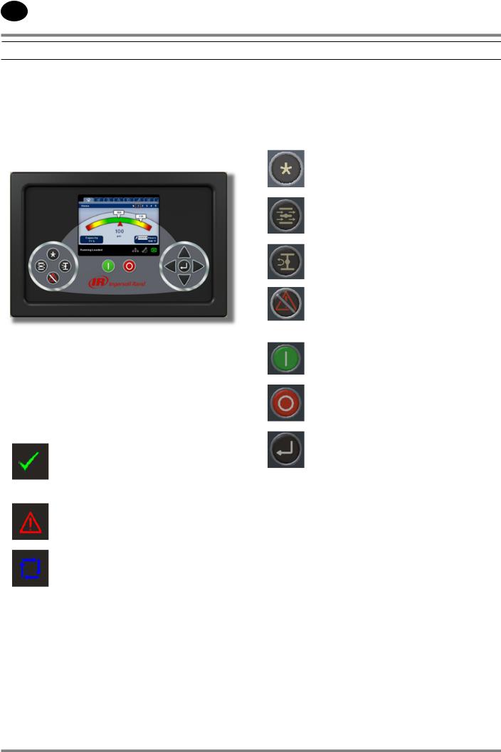
Xe-145M
The standard user interface configuration of the controller consists of the membrane and the LCD display. The membrane consists of five command keys (Start, Stop, Load, Unload, and Reset), four navigation keys (Up, Right, Left and Down), and an Edit mode selection key (Enter). These keys, in conjunction with the color graphics display and the LED icons, make up the user interface to the compressor.
Figure : Xe-145M
LED STATUS ICONS
Three LED icons are used to indicate the current status of the control system from a distance and are located on the upper left side of the user interface.
Icon |
Name |
Function |
|
|
|
|
|
Illuminates when no |
|
|
Warnings or Trips are sensed. |
|
OK |
Can be in a Ready or Not |
|
Ready state. This icon will |
|
|
|
|
|
|
flash when the machine is |
|
|
Running Unloaded |
|
|
Illuminates when an Warning |
|
Alert |
(flashes) or Trip (constant on) |
|
is sensed. Can be in a Ready |
|
|
|
|
|
|
(Warning) or Tripped state. |
|
|
|
|
Auto |
Illuminates when the |
|
compressor stops in auto |
|
|
|
restart. |
|
|
|
COMMAND KEYS
These keys command the controller to perform actions as specified in the following table. When any of these keys are pressed the action below will be initiated and logged in the event log.
Key |
Name |
Function |
|
--- |
None |
|
|
|
|
|
Puts the compressor into the |
|
Load |
selected mode of operation. |
|
Unit will load if the pressure |
|
|
|
|
|
|
conditions are right. |
|
|
|
|
Unload |
Puts the compressor into an |
|
unloaded state. Unit will run |
|
|
|
unloaded indefinitely. |
|
|
|
|
Reset |
Clears Warnings and Trips |
|
once the condition is |
|
|
|
corrected. |
|
|
|
|
|
|
|
Start |
Starts the compressor. |
|
|
|
|
|
Stops the compressor. This |
|
Stop |
button should be pressed |
|
instead of the E-Stop for |
|
|
|
|
|
|
normal stopping operation. |
|
Enter |
Toggles the display between |
|
the Navigation mode and the |
|
|
|
Edit mode. |
|
|
|
Xe-145M Command Keys
24519472 Rev B
112213.16.20
EN
INTERFACE DATA & KEYS
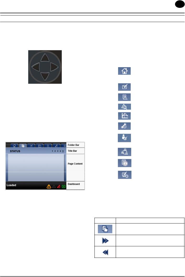
NAVIGATION KEYS
There are four navigation keys (UP, RIGHT, DOWN and LEFT). While the ENTER key is not considered a navigation key, it is used in conjunction with the navigation keys to make or confirm a selection.
Xe-145M’s Navigation Keys
The navigation keys roll over.. Pressing one of the navigation keys will lead the user down a navigation path. Each time
the key is pressed, another step in the path is taken. Once the end of a navigation path is reached, pressing the key one more time will bring the user back to the beginning of the path. Pressing the opposite key will move the user through the navigation path in the opposite direction. Once the beginning is reached, pressing the opposite key will take the user to the end of the path.
DISPLAY LAYOUT
Xe-145M’s Display Layout
Folder Bar: |
Uses tabs to graphically identify each |
|
folder. |
Title Bar: |
Identifies current folder and page |
|
(underlined). |
Page |
Content of the current page. |
Content: |
|
Dashboard: |
Displays system status. |
•FOLDER NAVIGATION & ICONS
To move among the tabbed folders shown on the LCD display, press the RIGHT and LEFT keys. The navigation rolls over from the last to the first folder and vice-versa.
Folder |
Icon |
Description |
|
Name |
|||
|
|
||
|
|
System performance and status |
|
|
|
main information. The first page |
|
Home |
|
of this folder is the default page |
|
|
|
when the controller first powers |
|
|
|
up. |
|
Operator |
|
System options and configuration |
|
Settings |
|
settings. |
|
|
|
|
|
Events |
|
System events log. |
|
|
|
|
|
Trip History |
|
Details on the most recent trips. |
|
|
|
|
|
Graphing |
|
On-board graphing of system |
|
|
data. (Xe-145M Only) |
||
|
|
||
|
|
|
|
Maintenance |
|
Status and notification setup for |
|
|
compressor maintenance items. |
||
|
|
||
|
|
|
|
General |
|
General settings such as |
|
|
Language, Time, and Units of |
||
Settings |
|
||
|
Measure. |
||
|
|
||
Integral |
|
Intergral Sequencing |
|
|
communication status and |
||
Sequencing |
|
||
|
configuration. |
||
|
|
||
Status |
|
Measurements or status from/of |
|
|
all analog and digital I/O. |
||
|
|
||
Factory |
|
Compressor tuning parameters. |
|
|
Also displays hardware and |
||
Settings |
|
||
|
software versions. |
||
|
|
Folder Bar Icons
•PAGE NAVIGATION
Once the desired folder is selected, press the DOWN key to move to the page selection area and then use the RIGHT and LEFT keys to select the desired page. Use the UP key to get back to the folder tabs.
Icon Description
Start of the page selection area.
Indicates that there are more pages available by navigating right.
Indicates that there are more pages available by navigating left.
Title Bar Page Icons
24519472 Rev B |
7 |
112213.16.20
EN
INTERFACE DATA & KEYS
•ACCESSING PARAMETERS
After the desired page is selected, the page’s parameters can be selected by using the DOWN key. The cursor will move to the next parameter each time the DOWN key is pressed. Use the UP key to go back to the previous one.
The cursor rolls over, so once the last parameter is selected, pressing the DOWN key will navigate the cursor to the Folder Bar. If the first parameter is selected, pressing the UP key will move the cursor to the page selection area.
Once selected, access parameters by pressing the ENTER key. Make changes using the NAVIGATION keys and then enter the setting by pressing the ENTER key again. After a parameter
is accessed, pressing the ENTER key will enter the current setting into the control program and navigate the cursor back to the selected parameter on the page.
When the cursor is on a parameter that has an enabled/ disabled box, pressing the ENTER key will cause the setting to toggle.
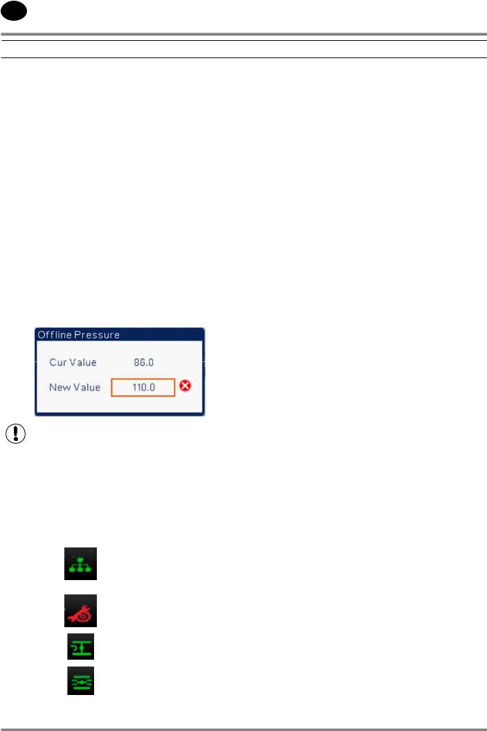
The icon  appears on numeric entry windows (see figure below). Placing the cursor on it and then pressing the ENTER key will cancel the entry and any changes that were made.
Not all pages have adjustable parameters. Some just have read-only information.
•DASHBOARD ICONS
The dashboard is intended to be a quick at-a-glance view of system status. The following table lists standard dashboard icons and their definition. Note that the color of these icons changes based on the state set by the application while running.
Name |
Icon |
Description |
Remote |
|
Remote control is enabled. This |
Control |
|
can be Remote Start/Stop, COM |
|
|
Control, Integral Sequencing or |
|
|
Web Control. |
Service |
|
A service reminder is nearing or |
Required |
|
has expired (i.e.: an air or oil filter |
|
|
needs to be changed). |
|
|
|
Unloaded |
|
Compressor is in the unloaded |
or |
|
state. |
|
|
|
Loaded |
|
Compressor is in the loaded state. |
|
|
|
Xe-145M’s Dashboard Icons
•DASHBOARD STATUS MESSAGES
The dashboard also displays the current operating state of the compressor. The following states can be encountered during machine operation:
•Ready to Start - – The compressor currently has no trip or start inhibit conditions present. The machine can be started by pressing the start button at any time
•Starting – A start command has been given to the compressor and the start sequence is being performed. The time period for this state can vary depending on the starter type of the machine.
•Load Delay – The compressor is waiting for a small period of time after starting before allowing the machine to load. This ensures the machine is at operating conditions before loading
•Running Loaded – The compressor is operating and producing air. The inlet valve is open and the blowoff valve is closed.
•Running Unloaded – The compressor is operating, but not producing air. The inlet valve is closed and the blowoff valve is open.
•Auto-Restart – The compressor has stopped due to pressure rising above the offline or auto-stop setpoints and auto-restart being enabled. The compressor will automatically restart when pressure falls to the online or target pressure setpoint.
•Stopping – The compressor has received a stop command and the stop sequence is being performed.
•Blowdown – The compressor must wait for a brief period of time after stopping its motor before it is allowed to start again.
•Not Ready – The compressor has detected a condition that will not allow the compressor to start. The condition must be cleared before a start is allowed, but does not need to be acknowledged.
•Tripped – The compressor has detected an abnormal operational condition that has stopped the machine. A trip must be acknowledged by hitting the reset button before the compressor can start.
•Processor Init – The controller is being initialized.
24519472 Rev B
112213.16.20
EN
SSR COMPRESSOR
 HOME FOLDER
Starts - Indicates the number of times a start is attempted on the compressor.
Date & Time – Indicates the current date and time. This is adjustable and configurable in the GENERAL SETTINGS folder.
All information on this page is read only.
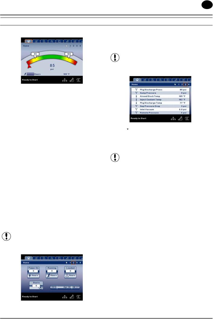
•PAGE 1 – SYSTEM OVERVIEW
This is the factory default display after powering up the system.
Load Pressure - indicated in the white box and by the white arrow, which is always left of center on the gauge. The compressor will load when package discharge pressure falls below this value.
Unload Pressure - indicated in the white box and by the white arrow, which is always right of center on the gauge. The compressor will unload when package discharge pressure rises above this value.
Package Discharge Pressure - indicated by the large numbers centred below the gauge and by the red arrow. This is the air pressure that the compressor is supplying to the plant.
Pressure Unit of Measure - indicated below the Package Discharge Pressure. This is selectable from the GENERAL SETTINGS folder.
Airend Discharge Temperature - indicated by the numbers in the lower left of the display. This is the temperature of the air/oil mixture at the discharge of the compression module.
Temperature Unit of Measure - indicated to the right of the Airend Discharge Temperature. This is selectable from the GENERAL SETTINGS folder.
Run Hours indicate the number of hours the compressor has been running.
All information on this page is read only.
•PAGE 2 - COUNTERS
Hour Meters - Indicates the hours that: the controller has been powered up, the compressor has been running, and the compressor has running loaded.
•PAGES 3 THRU 4 – ANALOG INPUTS
Pressure  is indicated by this icon. Temperature
  is indicated by this icon.
Any sensor that is not installed or is reporting a failure will show an X symbol.
All information on these pages is read only.
The following analog inputs are displayed in this section.
Package Discharge Pressure – The pressure the compressor is delivering to the plant.
Sump Pressure – The compressor’s internal pressure at the sump tank.
Airend Discharge Temperature – The temperature of the air/oil mixture at the discharge of the compression module.
Injected Coolant Temperature – The temperature of the oil as it is injected into the compression module.
Package Discharge Temperature – The temperature of the air after passing through the After-cooler.
Separator Pressure Drop – The pressure drop across the separator element.
Inlet Vacuum – Vacuum reading at the inlet valve.
Remote Pressure (optional) – An optional pressure sensor that reads pressure at a point outside of the compressor package. Usually this would be on a common tank.
Percent Load – Displays the current operating load percentage of the compressor based on the inlet valve position if it is in a modulation mode. While modulating, the minimum value will be 60% If running in online/offline mode, this value will be 100% (Loaded) or 0% (Unloaded).
24519472 Rev B |
9 |
112213.16.20
EN
SSR COMPRESSOR
 OPERATOR SETTINGS FOLDER
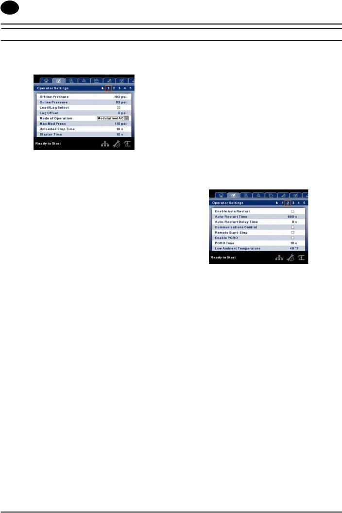
•PAGE 1 OPERATOR SETTINGS
The below values are all setpoints.
Offline Pressure – The compressor will unload when package discharge pressure rises above this value. Range (in PSI): 75 to Rated Pressure + 3
Online Pressure – The compressor will load when the package discharge pressure falls below this value Range (in PSI): 65 to Offline Pressure - 10
Lead/Lag – When this box is checked the compressor is operating as a lead machine. Unchecking the box causes the machine to run as a lag machine.
Lag Offset – If the machine is running as a lag compressor, the lag offset will be subtracted from the online and offline setpoints.
Range (in PSI): 0 – 45, depending on the online and offline setpoints. The Lag Offset will never allow you to exceed the minimum or maximum values of the online and offline setpoints.
Mode of Operation – Selections are Online/Offline, Modulation/ACS, and Modulation only – determines how the compressor will try to maintain a specific pressure.
•Online/Offline – The compressor will load the machine by energizing a solenoid that opens the inlet valve and closes the blowdown valve when package discharge pressure falls below the load pressure. The compressor will unload the machine by de-energizing the solenoid when pressure rises above the unload pressure.
•Modulation – The compressor will still load and unload as in online/offline, but will change the position of
the inlet valve using a stepper motor to adjust the compressor capacity between 60% and 100% of normal. When the package discharge pressure is between the load and unload pressures the compressor will adjust the inlet valve in order to achieve a stable output pressure. The output pressure target l is determined by the maximum modulation pressure setpoint.
•Mod/ACS – The compressor will initially start out in online offline mode. If the compressor goes through 3 load/unload cycles within 3 minutes, it will switch over into Modulation mode. It will remain in modulation until the stop button is pressed or 3 minutes pass between an unload and load command.
Maximum Modulation Pressure – When the compressor is in a modulating mode, this is the pressure value at which the compressor will unload. The compressor will start to modulate its output 10 psi (.7 bar) below this value and reach 60% of load by the time this setting is reached. This setting can be changed independently of the offline pressure setpoint.
Unloaded Stop Time – Time period that the machine must run unloaded before the motor is allowed to stop after a stop command is received.
Range (in seconds): 10 - 30.
Starter Time – Time period that the compressor needs in order to come up to operating speed after a start command before being able to produce air.
Range (in seconds): 5 - 30.
The parameters on these pages are adjustable any time
•PAGES 2-4 OPERATOR OPTIONS
The below values are all setpoints
Enable Auto-Restart – Enabling this will allow the compressor to stop if it has been running unloaded for a period of time, and the motor has exceeded its minimum running time (10 minute in most cases).
Auto-Restart Time – The time period the compressor must run unloaded before stopping in auto-restart. This time period begins the moment that package discharge pressure rises above the offline setpoint. Both this time period and the minimum motor run timer (10 minutes) must be satisfied before the compressor will stop in auto restart.
Range (in seconds) 120 - 3600
Auto-Restart Delay – The time period after the package discharge pressure has fallen below the online setpoint before the compressor can automatically restart
Range (in seconds): 0 - 60
COM Control – Enabling this setpoint allows the compressor to be controlled by a serial or Ethernet device, such as an X8I. This is equivalent to the “Sequencer” option on older Intellisys controllers.
Remote Start/Stop – Enabling this setpoint allows the compressor to be started and stopped using the digital inputs on the controller.
10 |
24519472 Rev B |
112213.16.20
EN
SSR COMPRESSOR
Enable PORO – Enabling this setpoint will allow the compressor to automatically restart after a power outage has been restored if the compressor was running loaded at the time of the outage. PORO is an option and the option module must be purchased and installed before this feature can be turned on.
PORO Time – Time after the controller power has been restored and controller has finished booting before the compressor will perform a PORO start. During this time the PORO Horn will sound.
Range (in seconds): 10 - 600
Low Ambient Temp – Temperature below which the low ambient option will come into effect.
Range (in degF): 30 - 60
Scheduled Start Day – Day (or days) of the week for which a scheduled start will be performed. The compressor will start when its onboard clock matches the day, hour, and minute of the scheduled start setpoints. Scheduled Start/Stop is
an option and the option module must be purchased and installed before this feature can be turned on.
Scheduled Start Hour – Hour of the day for which a scheduled start will be performed. Scheduled Start/Stop is an option and the option module must be purchased and installed before this feature can be turned on.
Scheduled Start Minute – Minute of the hour for which a scheduled start will be performed. Scheduled Start/Stop is an option and the option module must be purchased and installed before this feature can be turned on.
Scheduled Stop Day – Day (or days) of the week for which a scheduled stop will be performed. The compressor will stop when its onboard clock matches the day, hour, and minute of the scheduled stop setpoints. Scheduled Start/Stop is
an option and the option module must be purchased and installed before this feature can be turned on.
Scheduled Stop Hour – Hour of the day for which a scheduled stop will be performed. Scheduled Start/Stop is an option and the option module must be purchased and installed before this feature can be turned on.
Scheduled Stop Minute – Minute of the hour for which a scheduled stop will be performed. Scheduled Start/Stop is an option and the option module must be purchased and installed before this feature can be turned on.
Enable High Dust Filter – Enabling this when a high dust filter is installed will adjust the change inlet filter warning and high inlet vacuum trip thresholds to a higher value.
Enable VSD - Enabling this setpoint allows the controller to start and stop an aftermarket VSD which has been installed in the compressor.
Enable Remote Pressure Sensor – Enabling this allows the compressor to load and unload based off a sensor reading installed in a remote location.
Please note that in order to disable Scheduled Start/Stop, the Scheduled Start and Stop days, hours, and minutes must match exactly.
*The low ambient temperature is only adjustable if the low ambient factory set point is on.
**A value of 0 will disable the lead/lag cycle time feature.
•PAGES 5 CALIBRATE SENSORS
Sensor calibration can only take place when the machine is stopped and there is no pressure on the sensor. Calibration only needs to take place after a sensor is replaced, the controller is replaced, the controller software is upgraded, or the operator suspects the sensor reading is in error. Calibrate a sensor by selecting the checkbox beside the sensor name.
Each of the sensors listed below can be calibrated.
•Inlet Vacuum (1AVPT)
•Sump Pressure (3APT)
•Package Discharge Pressure (4APT)
•Dry Side Sump Pressure – Only on units with the dry side sump pressure option
•Remote Pressure (10APT) – Only on units with the remote sensor option
Please note that if a sensor is currently reading a value that is +/- 10% of its range from zero, the sensor will not be able to be calibrated and an warning will be logged in the event log. Please make sure the sensor is being exposed to atmosphere before attempting calibration.
24519472 Rev B |
11 |

112213.16.20
EN
SSR COMPRESSOR
 EVENTS FOLDER
•PAGES 1 TO A MAX OF 50
The pages in the Events folder document up to the last 250 events that the controller has experienced, with the time and date of the occurrence. The events are recorded in sequence, with number one being the newest and 250 being the oldest. When a new event occurs, it becomes number one and all others are shifted up in number.
The page numbers in the Title Bar are used to scroll through the events, with each page displaying up to seven. Page one displays events one through five, page two displays six through ten, and so on.
The following items will generate an event
•Power On
•Power Off
•Press the Start Key
•Press the Stop Key
•Press the Load Key
•Press the Unload Key
•Starting the compressor remotely
•Stopping the compressor remotely
•Warning
•Trip
•Start Inhibit
Active Warnings will be highlighted in amber while acknowledged Warnings will have amber text.
Active Trips will be highlighted in red while acknowledged Trips will have red text.
Active Start Inhibits will be listed in the Event log, but not highlighted. The display will indicate the compressor is not ready to start if a start inhibit is active.
Warning Events List
•Change Inlet Filter
On-Screen Text: Change Inlet Filter
Will occur if 1AVPT is greater than 0.7 psi vacuum for units rated in horsepower, or 1 psi for units rated in kilowatts ( 1.3 psi vacuum for all units if the high dust filter option is enabled) the unit has been loaded for at least 8 seconds and
the inlet valve is on the open limit switch. This condition must exist for 3 seconds before the warning is issued.
•Change Coolant Filter
On-Screen Text: Change Coolant Filter
This will occur if the coolant filter switch closes while the unit has been loaded for at least 7 seconds and the injected coolant temperature is over 120 degF. The condition must exist for 3 seconds before the warning is issued.
•Sensor Failure
On-Screen Text: 4ATT Failure, 6APT Failure
This will occur whenever sensors 4ATT, or 6APT are recognized as missing or broken. The sensor failure message shall follow the following format: 4ATT FAILURE. This condition must exist for 3 seconds before the warning is issued.
•Change Separator Element
On-Screen Text: Change Sep Element
Will occur if the unit is loaded for at least 8 seconds, the package discharge pressure (4APT) is at least 90 psi, is warmed up (injected coolant temperature greater than 120 degF), and the separator pressure drop is greater than 12 psi. This condition must exist for 3 seconds before the warning is issued.
•High Airend Discharge Temperature
On-Screen Text: High A/E Disch T
Will occur if the unit is running and 2ATT is greater than 221 degF (97% of 228) and the unit is running. This condition must exist for 3 seconds before the warning is issued.
•High Sump/Line Differential
On-Screen Text: High Sump/Line Dif
Will occur if the unit is loaded, has been loaded for at least 7 seconds, the injected coolant temperature is over 120 degF, the package discharge pressure is greater than 90 psi, the sump pressure is greater than the rated pressure of the unit,, and the sump pressure is 25 psi or more above the package discharge pressure. This condition must exist for 3 seconds before the warning is issued.
12 |
24519472 Rev B |

112213.16.20
EN
SSR COMPRESSOR
•Auxiliary 1
On-Screen Text: Auxiliary 1
This will occur if auxiliary input 1 closes. The contact must be closed for at least 3 seconds before the warning will occur.
•Auxiliary 2
On-Screen Text: Auxiliary 2
This will occur if auxiliary input 2 closes. The contact must be closed for at least 3 seconds before the warning will occur.
Service
Service warnings occur when the unit has operated a certain number of hours, based on the total hours. Service warnings can have multiple levels, depending on the service level selection. A service level selection of 0 disables service warnings.
•Service Level 1
On-Screen Text: SVC Required
If service level 1 has been selected for the unit, a “SERVICE REQUIRED” warning will be issued on hour intervals equal to the service time period set point. This warning can be reset the same as any other warning.
•Service Level 2
On-Screen Text: 100 hours to Svc, SVC Required, Service Alarm
If service level 2 has been selected for the unit, the service complete factory set point will be used to clear a level 2 service warning and reset the service time or date. The service complete can be reset before a service warning occurs.
The initial “SERVICE REQUIRED” warning will occur at total hour intervals equal to the service time period set point. However, 100 hours before this a “100 HOURS TO SERVICE” warning will occur. This warning can be reset the same as any other warning. One hundred hours later the “SERVICE REQUIRED” warning will occur. This warning can be reset the same as any other warning, however this warning will return in 24 hours if the service complete factory set point has not be set. If the service complete has not been set, 100 hours later, the “ALARM – SERVICE REQUIRED” warning will be issued. This warning can only be cleared by the service
complete factory set point. Once the service complete factory set point is set, indicating the service is completed, the time for the next “SERVICE REQUIRED” warning will be calculated by adding the service time period to the total hours value, with the “100 HOURS TO SERVICE” warning occurring 100 hours before and the “ALARM – SERVICE REQUIRED” warning occurring 100 hours after that time.
•Check Inlet Control System 1 (or 2)
On-Screen Text: Check Inlet Ctl 1, Check Inlet Ctl 2
Will occur if the controller tries to move the inlet valve to either the open limit switch or the closed limit switch and the inlet valve does not reach the limit switch it was moving toward. A 1 indicates the inlet valve was trying to close and a 2 indicates the valve was trying to open.
•Sensor Failure 10APT – Remote Sensor
On-Screen Text: 10APT Failure
This will occur if the remote sensor option is on and the remote sensor is recognized as missing or broken. If this occurs, the unit will automatically start using 4APT for loading and unloading the compressor. Units equipped with an integrated dryer cannot have a remote pressure sensor. This condition must exist for 3 seconds before the warning is issued.
•High Discharge Pressure
On-Screen Text: High Disch Pres
Will occur if the unit is using a remote sensor or is under the control of an external device, such as an X8I, is loaded, and the discharge pressure (4APT) is greater than the maximum offline pressure. This condition must exist for 3 seconds before the warning is issued. If this condition occurs, the compressor will automatically unload. The unit will be available to reload once the discharge pressure falls to the rated pressure value.
24519472 Rev B |
13 |

112213.16.20
EN
SSR COMPRESSOR
•Invalid Calibration
On-Screen Text: Invalid Cal
Will occur if the sensor zero value is +/- 10% of its scale. See Sensor Calibration.
•Starter Fault 1SL (2SL)
On-Screen Text: Starter Fault 1SL, Starter Fault 2SL
Will occur if the unit tries to start and either of the starter auxiliary contacts are already closed.
•Check SD Card
On-Screen Text: Check SD Card
The controller has detected a problem with the SD card during the last boot cycle and is using files from internal memory. The controller will function normally, but web page access may not work properly.
Trip Events List
•Check Inlet Control System
On-Screen Text: Check Inlet Ctl
This will occur if the unit is running unloaded and 1AVPT (inlet vacuum) is less than 3 psi vacuum. Also, the unit must have completed the start sequence, the inlet valve must be on the closed limit switch, and the unit must have been unloaded for a period of time at least equal to the stop delay time. This trip will also be ignored if the unit has an aftermarket VSD.
•Low Unloaded Sump Pressure
On-Screen Text: Low Unload Sump
Will occur if the unit is running unloaded or loaded and 3APT is less than 15 psi for 15 seconds. This trip will cause the unloaded inlet vacuum to be reset to 0. This will force the controller to get a new unloaded inlet vacuum value the next time the unit unloads
•Low Sump Air Pressure
On-Screen Text: Low Sump Air Press
Will occur if the unit is running loaded, the inlet valve is on open limit switch, and 3APT (sump pressure) is less than 20 psi. This trip is ignored for the first 7 seconds after loading.
•High Airend Discharge Temperature
On-Screen Text: High A/E Disch T
This will occur if 2ATT is greater than 228 degF and the unit is running.
•Check Motor Rotation
On-Screen Text: Check Motor Rot
Will occur if 1AVPT (inlet vacuum) is less than 0.5 psi vacuum, 2 seconds after starting (6 seconds if the unit is equipped with a soft starter or VSD). This condition can be caused by the motor running in reverse. Once correct motor rotation is established, this trip will not be checked again unless power is removed from the controller. However, if correct motor rotation is not established, this fault will be checked after each start until correct motor rotation is established. Correct motor rotation is established when the controller reads a sump pressure of 1 psi or more within 3 seconds of starting.
•Main Motor Overload
On-Screen Text: Main Motor OL
This will occur if the motor overload relay opens. The contact must be open for at least 3 seconds before the trip will occur.
•Fan Motor Overload
On-Screen Text: Fan Motor OL
Will occur if a fan motor overload relay contact opens. The contact must be open for at least 3 seconds before the trip will occur.
•Remote Stop Failure
On-Screen Text: Rem Stop Fail
Will occur if the remote start/stop option is enabled, the remote stop button remains open and either start button is pressed.
•Remote Start Failure
On-Screen Text: Rem Start Fail
Will occur if the remote start/stop option is enabled, the unit is started by the remote start button, and the button stays closed for 7 seconds after the unit starts.
•Stepper Limit Switch
On-Screen Text: Stepper Limit Switch
This will occur if the controller reads both the open and closed limit switches as being made at the same time.
•Sensor Failure
On-Screen Text: 1AVPT Failure, 3APT Failure, 4APT Failure, 2CTT Failure, 2ATT Failure, 3CTT Failure
This will occur when a sensor is recognized as missing or broken. The sensors affected by this trip are 1AVPT, 3APT, 4APT, 2CTT, 3CTT, and 2ATT. The sensor should be displayed along with the sensor failure message. The sensor failure message shall follow the following format: 1AVPT Failure.
•Emergency Stop
On-Screen Text: Emergency Stop
This will occur when the EMERGENCY STOP button is engaged.
•High Inlet Vacuum
On-Screen Text: On-Screen Text: High Inlet Vac
This will occur if the unit has running loaded for at least 8 seconds, the open limit switch is closed and the inlet vacuum is greater than 1.8 psi. If the unit has a high dust filter, the trip threshold for inlet vacuum is 2.4 psi.
14 |
24519472 Rev B |
112213.16.20
EN
SSR COMPRESSOR
•Start Inhibit List
High Airend Discharge Temperature On-Screen Text: High A/E Disch T
This will occur if 2ATT is greater than 95% of 228 degF.
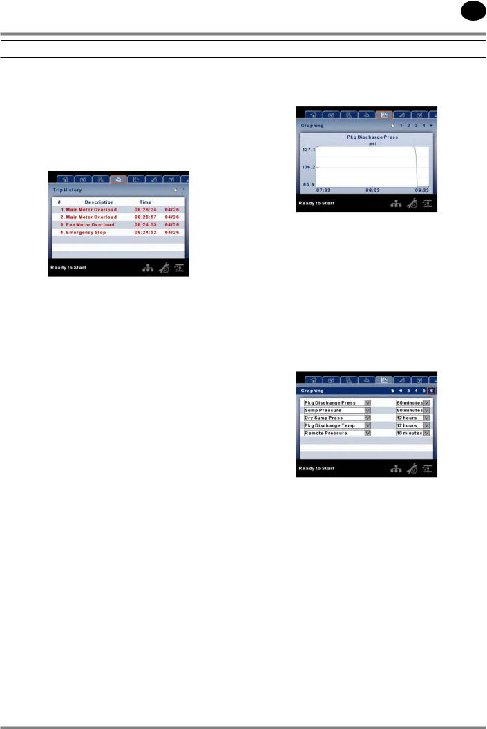
 TRIP HISTORY
•PAGES 1 TO A MAX OF 3
The pages in the Trips History folder document up to the last 15 trips that the controller has experienced, and time stamps each. The trips are recorded in sequence, with number one being the newest and 15 being the oldest. When a new trip occurs, it becomes number one and all others are shifted up in number.
The page numbers in the Title Bar are used to scroll through the events, with each page displaying up to seven. Page one displays events one through five, page two displays six through ten, and so on.
The following items will generate an entry in the trip history.
• Trips
Active Trips will be highlighted in red while cleared Trips will have red text.
The trip history also records compressor data at the time of the trip to assist in diagnostics and troubleshooting.
Navigating to the trip entry and hitting the enter button will bring up the trip history dialog box.
While the dialog box is active, press the left and right keys in order to scroll through the displayed data. The name of the trip will always be shown in the title bar of the dialog box. Press enter when finished viewing the data to return to the trip history screen
 GRAPHING FOLDER
•PAGES 1 THRU 5 – INDIVIDUAL GRAPHS
Variable (Read Only) Each page graphs one variable, displaying the variable name and unit of measure in the top center of the page. The variables that will be graphed on each of the five pages are selectable from page six. The units of measure are selectable from the GENERAL SETTINGS folder.
Y-Axis (Read Only) is auto-scaling.
X-Axis (Read Only - The time duration is selectable from page six. The sample rate varies, based on the selected duration.
The graph plots a minimum of 255 readings
•PAGE 6 – GRAPHING SELECTIONS
The selections for page one through five are organized sequentially in rows. The top row has page one selections and the bottom row has page five selections.
Variables - include all analog inputs as well as some calculated variables. The amount of variables will vary depending on the compressor type and the options it has.
Duration - selectable from the following five times
•10 minutes
•30 minutes
•60 minutes
•12 hours
•24 hours
These times are fixed and cannot be changed.
24519472 Rev B |
15 |

112213.16.20
EN
SSR COMPRESSOR
MAINTENANCE FOLDER |
• PAGE 3 - MAINTENANCE CONFIGURATION |
|
|
• PAGE 1 – FILTER STATUS |
|
This page displays the status of the filters. The filter status will either be “OK” or “Change” depending on the compressor’s diagnostic readings. If a filter reaches the “change’ status, a warning will be issued and the service indicator will light up yellow to notify the user. Please note that the compressor must be in a “Running Loaded” state to check these maintenance items. If the compressor is not in a running state
– the status will display “Load,” unless a maintenance indicator has been issued when the machine was running and has not yet been reset.
The following filters are displayed:
•Coolant Filter
•Separator Element
•Inlet Filter
•PAGE 2 – MAINTENANCE STATUS
This page displays the time until the unit should be serviced. The service meter will deplete as the hours count down closer to a service appointment. Once the counter reaches the yellow zone, the service indicator will light up yellow. Once the counter reaches the red zone the service indicator will light up red and maintenance must be performed.
This page allows the user to set the service interval and to reset the counter after the service has been performed. The service interval may be set to any value between 1000 and 8000 hours, but must be set in accordance with the factory maintenance schedule. After maintenance has been performed, the user can reset the counter by navigating to the Reset button and pressing the enter key.
 GENERAL SETTINGS FOLDER
All parameters in the general settings folder are adjustable.
•PAGE 1 – LANGUAGE SELECTION
Language (< >) is selectable from the following 30 selections:
English (default) |
Finish |
Latvian |
Slovak |
Bulgarian |
French |
Lithuanian |
Slovenian |
Chinese, simplified |
German |
Maltese |
Spanish |
Croatian |
Greek |
Norwegian |
Swedish |
Czech |
Hungarian |
Polish |
Thai |
Danish |
Italian |
Portuguese |
Turkish |
Dutch |
Indonesian |
Romanian |
|
Estonian |
Korean |
Russian |
|
The controller will display all screens in the selected language and only one language can be selected at a time.
Each language appears in its native translation.
16 |
24519472 Rev B |
Loading...