


Ingersoll Rand System Automation ir-485 & irV-485 Gateway Instruction Manual
Before installing or starting this unit for the first time, this manual should be studied carefully to obtain a working knowledge of the unit and or the duties to be performed while operating and maintaining the unit.
RETAIN THIS MANUAL WITH UNIT. This Technical manual contains IMPORTANT SAFETY DATA and should be kept with the unit at all times.
More Than Air. Answers.
Online answers: http://www.ingersollrandproducts.com
C.C.N. : 80444094 REV. : D
DATE : OCTOBER 2009

Section 1 - TABLE OF CONTENTS
Section 1 - TABLE OF CONTENTS.............................. |
2 |
SECTION 2 - INTRODUCTION....................................... |
3 |
SECTION 3 -safety........................................................ |
3 |
SAFETY PRECAUTIONS............................................................. |
3 |
INSTALLATION.............................................................................. |
3 |
OPERATION .................................................................................. |
3 |
MAINTENANCE AND REPAIR.................................................. |
3 |
SECTION 4 - COMPRESSOR CONNECTION AND |
|
CONTROL.......................................................................... |
5 |
COMPRESSOR CONNECTION AND CONTROL................. |
5 |
SECTION 5 - INSTALLATION OVERVIEW.................... |
6 |
INSTALLATION.............................................................................. |
7 |
UNIT LOCATION........................................................................... |
7 |
POWER SUPPLY........................................................................... |
7 |
AUTOMATION SYSTEM CONNECTION............................... |
8 |
AUTOMATION SYSTEM COMMUNICATIONS.................... |
8 |
COMPRESSOR ir-BUS / MODBUS CONNECTION.......... |
8 |
COMPRESSOR COMMUNICATIONS..................................... |
9 |
RS485 NETWORK......................................................................... |
9 |
Compressor Identification Number...................... |
10 |
SPECIFIC TO THE ir-485 Gateway.................................... |
11 |
SPECIFIC TO THE irV-485 Gateway.................................. |
12 |
Operational Indications............................................... |
13 |
SECTION 6 |
- parts list.............................................. |
15 |
SECTION 7 |
- Technical Data................................... |
15 |
SECTION 8 |
- NOTES...................................................... |
15 |
Refer to Section Indicated
Note
Important or Caution, Safety
SECTION 2 - INTRODUCTION
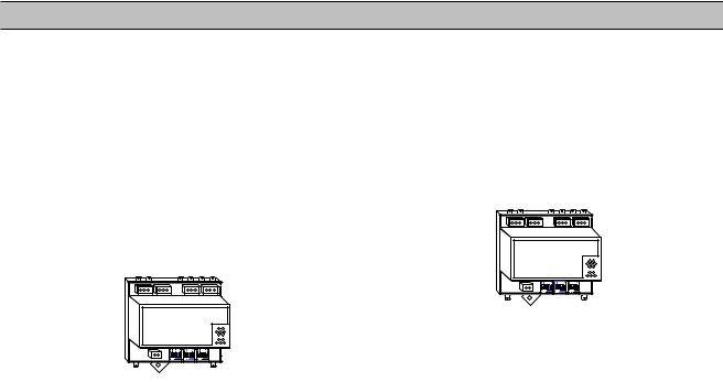
The ir-485 Gateway is designed to interface the Intellisys Controllers (Non-Nirvana) on Ingersoll Rand Compressors with the X8I or X12I Automation System via the RS485 Network.
The irV-485 Gateway is designed to interface an Ingersoll Rand Nirvana, VSD Rotary Compressors, 20 HP (15KW) and above, with the X8I or X12I Automation System via the RS485 Network.
Both Gateways are designed to be DIN Rail mounted within the compressor control gear enclosure but can alternatively be mounted remotely within a separate enclosure.
SECTION 3 -safety
SAFETY PRECAUTIONS
!WARNING : Risk of Danger
WARNING : Risk of Electric Shock
! |
WARNING : Risk of High Pressure |
|
WARNING : Consult Manual
•Before installing or operating the ir485 / irV485 GATEWAY, take time to carefully read all the instructions contained in this manual, all compressor manuals, and all manuals of any other peripheral devices that may be installed or connected to the unit.
•Electricity and compressed air have the potential to cause severe personal injury or property damage.
•The operator should use common sense and good working practices while operating and maintaining this system. All applicable codes should be strictly adhered to.
•Maintenance must be performed by adequately qualified personnel that are equipped with the proper tools.
INSTALLATION
•Installation work must only be carried out by a competent person under qualified supervision.
•A fused isolation switch must be fitted between the main power supply and the ir485 / irV485 GATEWAY.
•The ir485 / irV485 GATEWAY should be mounted in such a location as to allow operational and maintenance access without obstruction or hazard and to allow clear visibility of indicators at all times.
•If raised platforms are required to provide access to the ir485 / irV485 GATEWAY, they must not interfere with normal operation or obstruct access. Platforms and stairs should be of grid or plate construction with safety rails on all open sides.
OPERATION
•The ir485 / irV485 GATEWAY must only be operated by competent personnel under qualified supervision.
•Never remove or tamper with safety devices, guards or insulation materials fitted to the ir485 / irV485 GATEWAY.
•The 485 GATEWAY must only be operated at the supply voltage and frequency for which it is designed.
•When main power is switched on, lethal voltages are present in the electrical circuits and extreme caution must be exercised whenever it is necessary to carry out any work on the unit.
•Do not open access panels or touch electrical components while voltage is applied unless it is necessary for measurements, tests or adjustments. Such work should be carried out only by a qualified electrician equipped with the correct tools and wearing appropriate protection against electrical hazards.
•All air compressors and/or other equipment connected to the unit should have a warning sign attached stating “THIS UNIT MAY START WITHOUT WARNING” next to the display panel.
•If an air compressor and/or other equipment connected to the unit is to be started remotely, attach two warning signs to the equipment stating “THIS UNIT CAN BE STARTED REMOTELY”. Attach one sign in a prominent location on the outside of the equipment, and the other sign inside the equipment control compartment.
MAINTENANCE AND REPAIR
•Maintenance, repairs or modifications must only be carried out by competent personnel under qualified supervision.
•If replacement parts are required, use only genuine parts from the original equipment manufacturer, or an alternative approved source.
•Carry out the following operations before opening or removing any access panels or carrying out any work on the ir485 / irV485 GATEWAY:
i.Isolate the ir485 / irV485 GATEWAY from the main electrical power supply. Lock the isolator in the “OFF” position and remove the fuses.
ii.Attach labels to the isolator switch and to the unit stating “WORK IN PROGRESS - DO NOT APPLY VOLTAGE”. Do not switch on electrical power or attempt to start the ir485 / irV485 GATEWAY if such a warning label is attached.
•Make sure that all instructions concerning operation and maintenance are strictly followed and that
the complete unit, with all accessories and safety devices, is kept in good working order.
•The accuracy of sensor devices must be checked on a regular basis. They must be calibrated when acceptable tolerances are exceeded. Always ensure any pressure within the compressed air system is safely vented to atmosphere before attempting to remove or install a sensor device.
•The ir485 / irV485 GATEWAY must only be cleaned with a damp cloth, using mild detergents if necessary. Avoid the use of any substances containing corrosive acids or alkalis.
•Do not paint the control face plate or obscure any indicators, controls, instructions or warnings.
SECTION 4 - COMPRESSOR CONNECTION AND CONTROL
COMPRESSOR CONNECTION AND CONTROL ir-485 Gateway
The ir-485 Gateway module is designed to interface to any Ingersoll Rand Intellisys controlled (Non-Nirvana) compressor. All IR compressors equipped with Intellisys controllers (Non-Nirvana) require this interface. Including:
IntelliSys “Red Eye”, SG and SE
 All Nirvana Compressors, 20 HP (15KW) and above require the irV-485 Gateway.
The X8I or X12I communicates to the ir-485 Gateway via a two wire, RS485 network utilizing the ir-485 protocol.
The ir-485 Gateway module is installed within the compressor control cabinet and connected to the X8I or X12I using Belden 9841 or equivalent RS485 cable.
irV-485 Gateway
The irV-485 Gateway module is designed to interface to any Ingersoll Rand Nirvana compressor. All Nirvana Compressors, 20 HP (15KW) and above require this interface. Including:
IntelliSys SGN, SGNe and Nirvana 15-30kW (20-40HP)
The X8I or X12I communicates to the irV-485 Gateway via a two wire, RS485 network utilizing the ir485 protocol.
The ir-485 Gateway module is installed within the compressor control cabinet and connected to the X8I or X12I using Belden 9841 or equivalent RS485 cable.
 Loading...