


OPERATOR’S MANUAL |
6661AX-X-C |
INCLUDING: OPERATION, INSTALLATION & MAINTENANCE
1” DIAPHRAGM PUMP
1:1 RATIO (NON-METALLIC)
RELEASED: 9-11-89 REVISED: 11-13-10 (REV. U)
READ THIS MANUAL CAREFULLY BEFORE INSTALLING,
OPERATING OR SERVICING THIS EQUIPMENT.
It is the responsibility of the employer to place this information in the hands of the operator. Keep for future reference.
SERVICE KITS
Refer to the Model Description Chart to match the pump material options. 637118-C for Air Section repair (see page 6).
637161-XX-C for Fluid Section repair (see page 4).
PUMP DATA
Models |
. . . . . . See Model Description Chart for “-XXX”. |
||
Pump Type . . . Non-Metallic, Air Operated, Double Diaphragm |
|||
Material . |
. . . . . See Model Description Chart. |
||
Weight 6661A3-, 1AF-, 1AJ-, 1AL- . |
. . |
20.25 lbs (9.19 kgs) |
|
|
6661AP-, 1AR-, 1AS-, 1AT- |
. . |
20.25 lbs (9.19 kgs) |
|
6661A4-, 1AG-, 1AK-, 1AN- |
. . |
28.5 lbs (12.93 kgs) |
|
6661B3-, 1BF-, 1BJ-, 1BL- . |
. . |
28.8 lbs (13.06 kgs) |
|
6661BP-, 1BR-, 1BS-, 1BT- |
. . |
28.8 lbs (13.06 kgs) |
|
6661B4-, 1BG-, 1BK-, 1BN- |
. . |
37 lbs (16.78 kgs) |
Maximum Air Inlet Pressure . . . . . . |
. . |
120 p.s.i. (8.3 bar) |
|
Maximum Material Inlet Pressure . . |
. . |
10 p.s.i. (0.69 bar) |
|
Maximum Outlet Pressure . . . . . . . |
. . |
120 p.s.i. (8.3 bar) |
|
Maximum Flow Rate (flooded inlet) . . . . |
47 g.p.m. (177.9 l.p.m.) |
||
Displacement / Cycle @ 100 p.s.i.g. |
. . |
0.17 gal. (0.64 lit.) |
|
Maximum Particle Size (semi-solids) . |
. . |
1/8” dia. (3.2 mm) |
|
Maximum Temperature Limits |
35_ to 175_ F (2_ to 79_C) |
||
|
Polypropylene . . . . . |
||
|
PVDF (Kynar) . . . . . |
10_ to 200_ F (-12_ to 93_ C) |
|
Dimensional Data . . . . . . . . . . . . . |
. . |
see page 8 |
|
Noise Level @ 70 p.s.i. - 60 c.p.m.{ . |
. |
64.5 db (A)| |
|
{ Tested with 93110 muffler installed.
|The pump sound pressure levels published here have been updated to an Equivalent
Continuous Sound Level (LAeq) to meet the intent of ANSI S1.13-1971, CAGI-PNEU- ROP S5.1 using four microphone locations.
NOTICE: All possible options are shown in the chart, however, certain combinations may not be recommended, consult a representative or the factory if you have questions concerning availability.
GENERAL DESCRIPTION
The ARO Diaphragm Pump offers high volume delivery even at low air pressure and a broad range of material compatibility options available. Refer to the model and option chart. ARO pumps feature stall resistant design, modular air motor / fluid sections.
Air operated double diaphragm pumps utilize a pressure differential in the air chambers to alternately create suction and positive fluid pressure in the fluid chambers, ball checks insure a positive flow of fluid.
Pump cycling will begin as air pressure is applied and it will continue to pump and keep up with the demand. It will build and maintain line pressure and will stop cycling once maximum line pressure is reached (dispensing device closed) and will resume pumping as needed.
INGERSOLL RAND COMPANY
209 NORTH MAIN STREET -- BRYAN, OHIO 43506
)$; |
E2010 CCN 81660326 |
www.ingersollrandproducts.com
6661XJ-XXX-C |
6661XF-XXX-C |
6661XK-XXX-C |
6661XG-XXX-C |
6661XL-XXX-C |
6661XR-XXX-C |
6661XN-XXX-C |
|
6661XS-XXX-C |
|
6661XT-XXX-C |
|
6661X3-XXX-C |
|
6661X4-XXX-C |
Figure 1 |
6661XP-XXX-C |
MODEL DESCRIPTION CHART
6661 X X - X X X - C
CENTER BODY MATERIAL
A - Aluminum |
B - Cast Iron |
FLUID CAP / MANIFOLD MATERIAL
3 - Colorless Polypropylene flange (3-piece manifold) 4 - PVDF (KynarR) flange (3-piece manifold)
F - Colorless Polypropylene flange (one piece manifold) G - PVDF (Kynar) flange (one piece manifold)
J - Colorless Polypropylene, N.P.T. (one piece manifold) K - PVDF (Kynar), N.P.T. (one piece manifold)
L - Colorless Polypropylene, B.S.P. (one piece manifold) N - PVDF (Kynar), B.S.P. (one piece manifold)
P - Gray Polypropylene flange (3-piece manifold) R - Gray Polypropylene flange (one piece manifold) S - Gray Polypropylene, N.P.T. (one piece manifold) T - Gray Polypropylene, B.S.P. (one piece manifold)
SEAT MATERIAL |
|
|
|
|
|
|
|
|
|
|
2 |
- 316 Stainless Steel |
4 |
- PVDF (Kynar) |
|
|
|
|
|
||
|
|
|
|
|
||||||
3 |
- Polypropylene |
|
8 |
- Hard 440 Stainless Steel |
|
|
|
|
|
|
|
|
|
|
|
|
|
|
|
|
|
|
|
|
|
|
|
|
|
|
|
|
BALL MATERIAL |
|
|
|
|
|
|
|
|
|
|
1 |
- Neoprene |
|
8 |
- Polyurethane |
|
|
|
|
||
2 |
- Nitrile |
|
A - 316 Stainless Steel |
|
|
|
|
|||
|
|
|
|
|
||||||
3 |
- VitonR |
|
E - SantopreneR |
|
|
|
|
|||
4 |
- PTFE |
|
M - Medical Grade Santoprene |
|
|
|
|
|||
5 |
- E.P.R. |
|
|
|
|
|
|
|
|
|
|
|
|
|
|
|
|
|
|
|
|
DIAPHRAGM MATERIAL |
|
|
|
|
|
|
|
|||
1 |
- Neoprene |
3 |
- Viton |
9 - HytrelR |
|
|
|
|||
2 |
- Nitrile |
5 |
- E.P.R. |
B - Santoprene |
|
|
|
|||
|
|
|
||||||||
4 |
- PTFE / Santoprene M |
|
- Medical Grade Santoprene |
|
|
|
||||
|
|
|
|
|
|
|
|
|
|
|
FLUID SECTION SERVICE KIT SELECTION |
6661XX - X X X - C |
||||
EXAMPLE: MODEL # 6661A3-311-C |
637161 - X X - C |
||||
FLUID SECTION SERVICE KIT # 637161-11-C |
BALL |
|
|
|
DIAPHRAGM |
|
|
|
|||
|
|
|
|
||
OPERATING AND SAFETY PRECAUTIONS
READ, UNDERSTAND AND FOLLOW THIS INFORMATION TO AVOID INJURY AND PROPERTY DAMAGE.
|
|
|
|
|
S Check pump motor section, fluid caps, manifolds and all |
||
|
|
|
|
|
|||
|
EXCESSIVE AIR PRESSURE |
HAZARDOUS MATERIALS |
|
wetted parts to assure compatibility before using with solvents |
|||
|
STATIC SPARK |
HAZARDOUS PRESSURE |
|
of this type. |
|||
|
|
|
|
|
|||
|
|
|
|
|
WARNING |
HAZARDOUSMATERIALS. Can cause seriousin- |
|
|
|
|
|
|
|
|
|
|
|
EXCESSIVE AIR PRESSURE. Can cause pump |
jury or property damage. Do not attempt to return a pump to the |
||||
|
WARNING |
||||||
|
damage, personal injury or property damage. |
factory or service center that contains hazardous material. |
|||||
S Be sure material hoses and other components are able to with- |
Safe handling practices must comply with local and national |
||||||
|
stand fluid pressures developed by this pump. Check all hoses |
laws and safety code requirements. |
|||||
|
for damage or wear. Be certain dispensing device is clean and |
S Obtain Material Safety Data Sheets on all materials from the |
|||||
|
in proper working condition. |
|
|
supplier for proper handling instructions. |
|||
S Do not exceed the maximum inlet air pressure as stated on the |
CAUTION |
Verify the chemical compatibility of the pump |
|||||
|
pump model plate. |
|
|
wetted parts and the substance being pumped, flushed or re- |
|||
|
|
|
circulated. Chemical compatibility may change with tempera- |
||||
|
WARNING |
STATIC SPARK. Can cause explosion resulting in |
|||||
|
severe injury or death. Ground pump and pumping system. |
ture and concentration of the chemical(s) within the |
|||||
S Sparks can ignite flammable material and vapors. |
substances being pumped, flushed or circulated. For specific |
||||||
S |
The pumping system and object |
being sprayed must be |
fluid compatibility, consult the chemical manufacturer. |
||||
|
grounded when it is pumping, flushing, recirculating or spray- |
CAUTION |
Maximum temperatures are based on mechani- |
||||
|
ing flammable materials such as paints, solvents, lacquers, |
cal stress only. Certain chemicals will significantly reduce |
|||||
|
etc. or used in a location where surrounding atmosphere is |
maximum safe operating temperature. Consult the chemical |
|||||
|
conducive to spontaneous combustion. Ground the dispens- |
manufacturer for chemical compatibility and temperature lim- |
|||||
|
ing valve or device, containers, hoses and any object to which |
its. Refer to PUMP DATA on page 1 of this manual. |
|||||
|
material is being pumped. |
|
|
CAUTION |
Be certain all operators of this equipment have |
||
S Secure pump, connections and all contact points to avoid |
been trained for safe working practices, understand it’s limita- |
||||||
|
vibration and generation of contact or static spark. |
tions, and wear safety goggles / equipment when required. |
|||||
S Consult local building codes and electrical codes for specific |
|||||||
CAUTION |
Do not use the pump for the structural support of |
||||||
|
grounding requirements. |
|
|
||||
|
|
|
the piping system. Be certain the system components are |
||||
S Aftergrounding,periodicallyverify continuityof electricalpath |
|||||||
properly supported to prevent stress on the pump parts. |
|||||||
|
to ground. Test with an ohmmeter from each component (e.g., |
||||||
|
S Suction and discharge connections should be flexible connec- |
||||||
|
hoses, pump, clamps, container, spray gun, etc.) to ground to |
||||||
|
insure continuity. Ohmmeter should show 0.1 ohms or less. |
tions (such as hose), not rigid piped, and should be compatible |
|||||
|
with the substance being pumped. |
||||||
S Submerse the outlet hose end, dispensing valve or device in |
|||||||
CAUTION |
Prevent unnecessary damage to the pump. Do |
||||||
|
the material being dispensed if possible. (Avoid free streaming |
||||||
|
not allow pump to operate when out of material for long periods |
||||||
|
of material being dispensed.) |
|
|
||||
S Use hoses incorporating a static wire. |
of time. |
||||||
S |
Use proper ventilation. |
|
|
S Disconnect air line from pump when system sits idle for long |
|||
S Keep inflammables away from heat, open flames and sparks. |
periods of time. |
||||||
S Keep containers closed when not in use. |
CAUTION |
Use only genuine ARO replacement parts to as- |
|||||
|
|
Pump exhaust may contain contaminants. Can |
sure compatible pressure rating and longest service life. |
||||
|
WARNING |
||||||
cause severe injury. Pipe exhaust awayfrom workarea andpersonnel.
SIn the event of a diaphragm rupture, material can be forced out of the air exhaust muffler.
SPipe the exhaust to a safe remote location when pumping hazardous or inflammable materials.
SUse a grounded 3/8” min. i.d. hose between the pump and the muffler.

 WARNING HAZARDOUS PRESSURE. Can result in serious injury or property damage. Do not service or clean pump, hoses or dispensing valve while the system is pressurized.
SDisconnect air supply line and relieve pressure from the system by opening dispensing valve or device and / or carefully and slowly loosening and removing outlet hose or piping from pump.

 WARNING EXPLOSION HAZARD. Models containing aluminum wetted parts cannot be used with III.-Trichloroethane, Methylene Chloride or other Halogenated Hydrocarbon solvents which may react and explode.
NOTICE Replacement warning labels are available upon request: “Static Spark PN \ 93122 & Diaphragm Rupture PN \ 93616-1.”
NOTICE RE-TORQUE ALL FASTENERS BEFORE OPERATION. Creep of housing and gasket materials may cause fasteners to loosen. Re-torque all fasteners to insure against fluid or air leakage.
|
|
= Hazards or unsafe practices which could |
|
WARNING |
|
|
|
result in severe personal injury, death or |
|
|
substantial property damage. |
|
|
= Hazards or unsafe practices which could |
|
CAUTION |
|
|
|
result in minor personal injury, product |
|
|
or property damage. |
|
|
= Important installation, operation or |
|
NOTICE |
|
|
|
maintenance information. |
|
|
|
PAGE 2 OF 8 |
6661AX-X-C |
AIR AND LUBE REQUIREMENTS

 WARNING EXCESSIVE AIR PRESSURE. Can cause pump damage, personal injury or property damage.
SA filter capable of filtering out particles larger than 50 microns should be used on the air supply. There is no lubrication required other than the “O” ring lubricant which is applied during assembly or repair.
SIf lubricated air is present, make sure that is compatible with the Nitrile “O” rings in the air motor section of the pump.
OPERATING INSTRUCTIONS
SAlways flush the pump with a solvent compatible with the material being pumped if the material being pumped is subject to ‘‘setting up” when not in use for a period of time.
SDisconnect the air supply from the pump if it is to be inactive for a few hours.
SThe outlet material volume is governed not only by the air supply but also by the material supply available at the inlet. The material supply tubing should not be too small or restrictive. Be sure not to use hose which might collapse.
SWhen the diaphragm pump is used in a forced-feed (flooded inlet) situation it is recommended that a “Check Valve” be installed at the air inlet.
SSecure the diaphragm pump legs to a suitable surface to insure against damage by vibration.
MAINTENANCE
Refer to the part views and descriptions as provided on page 4 through 7 for parts identification and Service Kit information.
SCertain ARO “Smart Parts” are indicated which should be available for fast repair and reduction of down time.
SService kits are divided to service two separate diaphragm pump functions: 1. AIR SECTION, 2. FLUID SECTION. The FLUID SECTION is divided further to match typical part MATERIAL OPTIONS.
SProvide a clean work surface to protect sensitive internal moving parts from contamination from dirt and foreign matter during service disassembly and reassembly.
MAINTENANCE CONTINUED
SKeep good records of service activity and include pump in preventive maintenance program.
SBefore disassembling empty captured material in the outlet manifold by turning the pump upside down to drain material from the pump.
FLUID SECTION DISASSEMBLY
1.Remove top manifold(s).
2.Remove (22) balls, (19 and 33) “O” rings and (21) seats.
3.Remove (15) fluid caps.
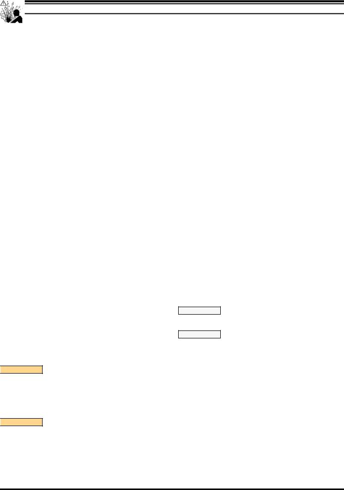
NOTE: Only PTFE diaphragm models use a (7) primary diaphragm and an (8) backup diaphragm. Refer to the auxiliary view in the Fluid Section illustration.
4.Remove the (6) nut, (7) or (7 / 8) diaphragms and (5) washers.
5.Remove (3 and 4) “O” rings.
NOTE: Do not scratch or mar the surface of (1) diaphragm rod.
FLUID SECTION REASSEMBLY
SReassemble in reverse order.
SClean and inspect all parts. Replace worn or damaged parts with new parts as required.
SLubricate (1) diaphragm rod and (2) “O” ring with Key-LubeR grease.
SUse ARO PN / 98930-T Bullet (installation tool) to aid in installation of (2) “O” ring on (1) diaphragm rod.
SBe certain (7) or (7 / 8) diaphragm(s) align properly with (15) fluid caps before making final torque adjustments on bolt and nuts to avoid twisting the diaphragm.
SFor models with PTFE diaphragms: Item (8) Santoprene diaphragm is installed with the side marked “AIR SIDE” towards the pump center body. Install the PTFE Diaphragm with the side marked “FLUID SIDE” towards the fluid cap.
SRe-check torque settings after pump has been re-started and run a while.
Fluid Side
Air Side 
Air
Side Fluid
Side
CROSS SECTION VIEW OF DIAPHRAGMS (Refer to figure 3, page 5)
31
5 |
8 |
7 |
6 |
24
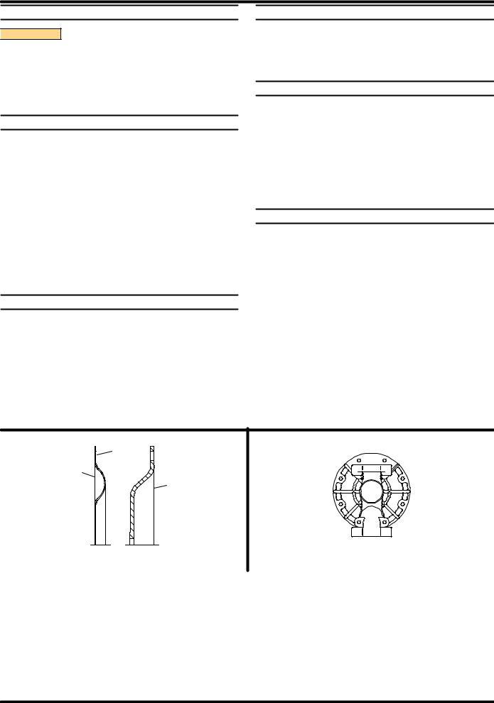
Torque Sequence
(Refer to figure 3, page 5)
Figure 2
S VitonR and HytrelR are trademarks of the DuPont Company S KynarR is a trademark of Penwalt Corp.
S SantopreneR is a trademark of the Monsanto Company, licensed to Advanced Elastomer Systems. L.P. S Key-LubeR is a registered trademark of Key Industries
6661AX-X-C |
PAGE 3 OF 8 |
 Loading...