Ingersoll-Rand 66942-XXX, 66941-XXX User Manual

OPERATOR’S MANUAL |
6694X-XXX |
INCLUDING: SERVICE KITS, TROUBLESHOOTING, PARTS LIST & DISASSEMBLY & REASSEMBLY.
TWO-BALL STYLE LOWER PUMP ENDS
66941-XXX (400 Series Stainless Steel)
66942-XXX (300 Series Stainless Steel)
Also covers 637211-XX3 service kits.
RELEASED: 11-27-90 REVISED: 6-2-10 (REV. R)
READ THIS MANUAL CAREFULLY BEFORE INSTALLING,
OPERATING OR SERVICING THIS EQUIPMENT.
It is the responsibility of the employer to place this information in the hands of the operator. Keep for future reference.
SERVICE KITS
yUse only genuine ARO® replacement parts to assure compatible pressure rating and longest service life.
y637211-XX3 for general repair of 6694X-XXX lower pump ends.
GENERAL DESCRIPTION

 WARNING DO NOT EXCEED MAXIMUM OPERATING PRESSURE AS INDICATED ON PUMP MODEL PLATE.
 WARNING REFER TO GENERAL INFORMATION SHEET FOR ADDITIONAL SAFETY PRECAUTIONS AND IMPORTANT INFORMATION.
yThis manual only covers the lower pump section. It is one of four documents which support an ARO pump. Replacement copies of these forms are available upon request.
650XXX-X Pump Model Operator’s Manual
General Information - Air / Hydraulically Operated Piston Pumps
:Lower Pump End Operator’s Manual
Air / Hydraulic Motor Operator’s Manual
yThe two-ball design provides better priming of the lower foot valve. The double acting feature is standard in all ARO industrial pumps. Material is delivered to the pump discharge outlet on both the up and down stroke.
MAINTENANCE
The air / hydraulic motor is completely separate from the lower pump end. This helps to keep the motor from being contaminated by the material being pumped. Periodically, flush the entire pump system with a solvent that is compatible with the material being pumped.
Keep the solvent cup filled with this compatible solvent. This will keep the material from drying on the piston rod, which could drag through the packings, ruin them and eventually scour the piston rod.
Provide a clean work surface to protect sensitive internal moving parts from contamination from dirt and foreign matter during disassembly and reassembly.
Before reassembly, lubricate parts as required. When assembling “O” rings or parts adjacent to “O” rings, exercise care to prevent damage to “O” rings and “O” ring groove surface.
INGERSOLL RAND COMPANY LTD
209 NORTH MAIN STREET – BRYAN, OHIO 43506
(800) 495-0276 FAX(800) 892-6276 |
© 2010 |
CCN 99711764 |
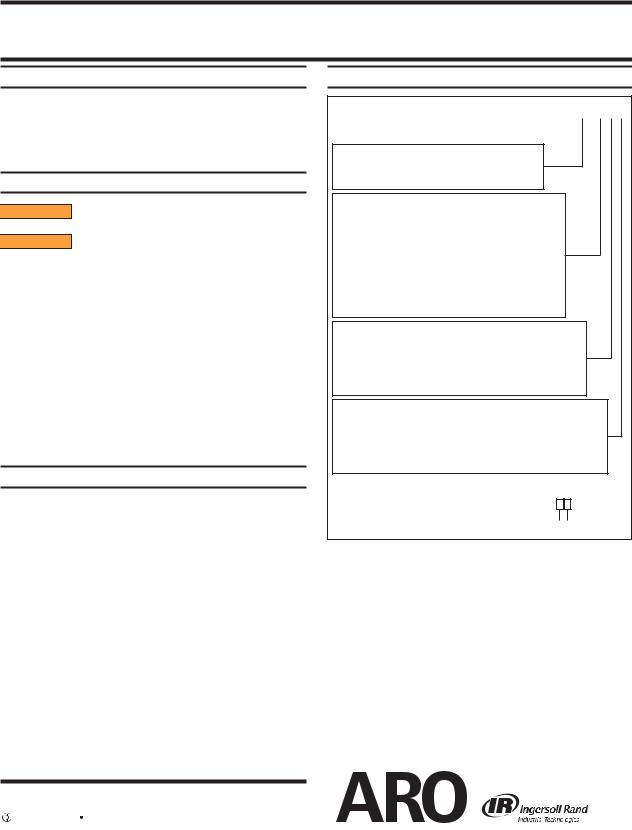
LOWER PUMP END DESCRIPTION CHART
6694X - X X X
Pump Material
1 - 400 series stainless steel
2 - 300 series stainless steel
Packing Material
C - UHMW-PE (upper and lower)
K - Carbon Graphite filled PTFE with Nitrile Energizer (upper and lower)
L - Mineral filled PTFE (upper and lower)
P - UHMW-PE / Mineral filled PTFE staggered (upper) UHMW-PE (lower)
R- Mineral filled PTFE / UHMW-PE staggered (upper) Mineral filled PTFE (lower)
Spring Arrangement (Service kit spring designation) 3 - No spring (3)
6 - Wave spring (6)
C - No spring with alternate seat material (3) D - Wave spring with alternate seat material (6)
Plunger Type
3 - Hardened stainless steel with hard chrome plating (threaded) 6 - Stainless steel with hard chrome plating (threaded)
D - Hardened stainless steel with hard chrome plating (large motors) F - Stainless steel with hard chrome plating (large motors)
Service Kit Selection |
6694X - X X X |
|
||||
EXAMPLE: Lower Pump End # 66941-CDF |
637211 - X X 3 |
|
||||
Packing |
|
|
|
|
Spring |
|
Service Kit # 637211-C63 |
|
|
|
|
||
|
|
|
|
|
|
|
|
|
|
|
|
|
|
yARO® is a registered trademark of Ingersoll-Rand y
yLoctite® and 242® are registered trademarks of Henkel Loctite Corporation y yPrimer T™ is a trademark of Henkel Loctite Corporation y
www.ingersollrandproducts.com

PARTS LIST / 6694X-XXX
Item |
|
Description (size) |
(Qty) |
Part No. |
[Mtl] |
1 |
|
Solvent Cup |
(1) |
66730 |
[SS] |
6 |
|
Pump Body |
(1) |
79166 |
[SS] |
98 |
|
“O” Ring (3/32” x 3-9/16” o.d.) |
|
|
|
|
|
(models 6694X-KXX) |
(2) |
93333 |
[B] |
|
|
(models 6694X-CXX, -LXX, -PXX, -RXX) |
(2) |
92619 |
[T] |
9 |
|
Suction Tube (models 66941-XXX) |
(1) |
92599-1 |
[SH] |
|
|
(models 66942-XXX) |
(1) |
79164 |
[SS] |
10 |
|
Tie Rod |
(3) |
79156 |
[SS] |
12 |
|
Nut (1” - 14) |
(3) |
79184 |
[SS] |
15 |
|
Foot Valve Body |
(1) |
92613 |
[SS] |
17 |
|
Ball (1.5000” o.d.) (models 66941-XXX) |
(1) |
Y16-148 |
[SH] |
|
|
(models 66942-XXX) |
(1) |
79155 |
[SS] |
20 |
|
Pin (5/16” o.d. x 3-7/16”) |
(1) |
79157 |
[SS] |
22 |
|
Ball Seat (models 66941-X3X, 66941-X6X) |
(1) |
92608 |
[SH] |
|
|
(models 66942-X3X, 66942-X6X) |
(1) |
77431 |
[SS] |
|
|
(models 6694X-XCX, 6694X-XDX) |
(1) |
95769 |
[TC] |
923 |
|
Gasket |
(1) |
92609 |
[SS] |
24 |
|
Seat Retainer |
(1) |
92607 |
[SS] |
26 |
|
Plunger (models 6694X-XX3) |
(1) |
60609 |
[PSH] |
|
|
(models 6694X-XX6) |
(1) |
61429 |
[PSS] |
|
|
(models 6694X-XXD) |
(1) |
67204 |
[PSH] |
|
|
(models 6694X-XXF) |
(1) |
67205 |
[PSS] |
27 |
|
Ball (1.0000” o.d.) (models 66941-XXX) |
(1) |
Y16-132 |
[SH] |
|
|
(models 66942-XXX) |
(1) |
90948 |
[SS] |
|
|
|
|
|
|
|
|
MATERIAL CODE |
|
|
|
[B] |
= Nitrile |
[SS] |
= Stainless Steel |
|
|
[Ny] |
= Nylon |
[T] |
= PTFE |
|
|
[PSH] = Hard Chrome Plated Hard Stainless Steel |
[TC] |
= Tungsten Carbide |
|||
[PSS] = Hard Chrome Plated Stainless Steel |
[UH] |
= UHMW-PE |
|
||
[SH] |
= Hard Stainless Steel |
|
|
|
|
LOWER PUMP DISASSEMBLY
1.Unscrew three (12) nuts from (10) tie rods.
2.Remove (15) foot valve body from (10) tie rods and (9) suction tube. NOTE: Use of a soft face mallet might be helpful to accomplish this step.
3.Note the position of (20) pin and (17) ball from (15) foot valve body.
4.Unscrew (24) seat retainer and remove (22) ball seat, (23) gasket and (8) “O” ring.
5.Pull (9) suction tube and (26) plunger from (6) pump body.
6.Push (26) plunger assembly out lower end of (9) suction tube.
7.Unscrew (36) seat body and remove (29) gasket, (27) ball and (28) ball seat from (26) plunger. NOTE: (36) seat body has two 0.250” dia. x 0.250” deep holes. Use a spanner wrench (ARO tool 637404-B is available) to loosen.
8.Remove (40) retaining ring from (36) seat body.
9.Remove (8) “O” ring from (6) pump body.
10.Unscrew (1) solvent cup from (6) pump body. NOTE: (1) solvent cup has six 3/8” dia. x 3/8” deep holes. Use a rod or spanner wrench (ARO tool 637406 is available) to loosen.
11.Remove (45) washer, (44) wave spring, (53) male washer, (51 and 52) packings and (50) female washer from (1) solvent cup.
Item |
Description (size) |
(Qty) |
Part No. |
[Mtl] |
28 |
Ball Seat (models 66941-X3X, 66941-X6X) |
(1) |
92610 |
[SH] |
|
(models 66942-X3X, 66942-X6X) |
(1) |
77430 |
[SS] |
|
(models 6694X-XCX, 6694X-XDX) |
(1) |
95770 |
[TC] |
929 |
Gasket |
(1) |
92612 |
[SS] |
36 |
Seat Body |
(1) |
93234 |
[SS] |
40 |
Retaining Ring |
(1) |
93225 |
[SS] |
944 |
Wave Spring (models 6694X-X6X, -XDX) |
(1) |
79175 |
[SH] |
945 |
Washer |
(1) |
93041 |
[Ny] |
950 |
Washer (models 6694X-CXX, -PXX) |
(1) |
93756-4 |
[UH] |
9 |
(models 6694X-LXX, -RXX) |
(1) |
93756-5 |
[T] |
951 |
“V” Packing (models 6694X-CXX, -PXX) |
(2) |
93683-4 |
[UH] |
9 |
(models 6694X-LXX, -RXX) |
(2) |
93683-5 |
[T] |
952 |
“V” Packing (models 6694X-CXX, -RXX) |
(2) |
93683-4 |
[UH] |
9 |
(models 6694X-LXX, -PXX) |
(2) |
93683-5 |
[T] |
953 |
Male Packing Washer (models |
(1) |
92602 |
[SS] |
|
6694X-CXX, -LXX, -PXX, -RXX) |
|
|
|
|
|
|
|
|
971 |
“W” Packing (models 6694X-CXX, -PXX) |
(1) |
93758-4 |
[UH] |
9 |
(models 6694X-LXX, -RXX) |
(1) |
93758-5 |
[T] |
972 |
Wiper (models 6694X-CXX, -PXX) |
(1) |
93757-4 |
[UH] |
9 |
(models 6694X-LXX, -RXX) |
(1) |
93757-5 |
[T] |
975 |
Packing (models 6694X-KXX only) |
(1) |
93568-1 |
[T] |
976 |
Packing (models 6694X-KXX only) |
(1) |
93567-1 |
[T] |
|
|
|
|
|
9 |
Items included in Service Kit |
|
637211-XX3 |
|
LOWER PUMP REASSEMBLY
All threads are right hand.
Apply lubricant to all rubber parts before assembling (it is not necessary to lubricate UHMW-PE and PTFE packings).
NOTE: All threads are to be cleaned before reassembly. The cleaning of threads is a benefit to help insure the overall reassembly process. Please note the use of the following materials: Loctite® Primer T™ with Loctite 242® Threadlocker and Loctite Nickel Anti-Seize.
All threaded parts are stainless steel and care should be taken on threaded connections.
Apply Loctite Nickel Anti-Seize to threads as indicated (figure 1, page 3) during assembly.
Apply ARO Wet-Sol "Plus" to threads as indicated (figure 1, page 3) during assembly.
Apply Primer T with Loctite 242 Threadlocker to threads as indicated (figure 1, page 3) during assembly. Follow these instructions to apply materials to threads.
a.Clean parts with solvent and allow to dry.
b.Apply Primer T to mating threaded parts and allow 3 to 5 minutes to dry at 72° F.
c.Apply Loctite 242 Threadlocker to mating threaded parts being assembled.
d.Assemble parts within 3 minutes of applying Threadlocker.
e.Tighten per "Torque Requirements", (see page 3).
f.Curing times: Fixed in 5 minutes and full cure in 2 hours. NOTE: If Primer T is not used, the cure time will be effected as follows: fixed in 20 minutes and full cure in 24 hours.
(continued on page 4)
Page 2 of 4 |
6694X-XXX (en) |
 Loading...