


 Loading...
80445570
Revision D January 2012
Ingersoll Rand System Automation
IX IntelliFlow
Operator’s Manual
DE
EN
ES
FR
IT
NL
Bedienungshandbuch
Operator’s Manual
Manual De Operadores
Manuel De L’utilisateur
Manuale D’uso
Gebruiksaanwijzingen
PRINT LANGUAGE
ENGLISH
DUTCH
FRENCH
GERMAN
ITALIAN
SPANISH
Save These Instruction

Section 1 - Table of contents
Section 1 - Table of contents.............................. |
2 |
DECLARATION OF CONFORMITY................................ |
3 |
SECTION 3 - INTRODUCTION....................................... |
4 |
SECTION 4 - Safety ..................................................... |
4 |
SAFETY PRECAUTIONS.............................................. |
4 |
SHIPMENT INSPECTION / PRE-INSTALLATION CHECK 4 |
|
INSTALLATION.............................................................................. |
4 |
operation................................................................................... |
4 |
MAINTENANCE AND REPAIR.................................................. |
5 |
SECTION 5 - CONNECTION AND CONTROL ............. |
6 |
OPERATING MODES .................................................................. |
6 |
SECTION 6 - INSTALLATION.......................................... |
8 |
IX INTELLIFLOW TECHNICAL DATA...................................... |
8 |
IX INTELLIFLOW INSTALLATION............................................ |
9 |
IX BOX POWER SUPPLY.......................................................... |
10 |
IX INTELLIFLOW VALVE CONTROLLER CONNECTION |
|
AND SENSOR ARRANGEMENT............................................ |
10 |
IX BOX RS485 NETWORK....................................................... |
11 |
SECTION 7 - DISPLAY AND MENU OPERATION ..... |
12 |
SECTION 8 - COMMISSIONING ................................. |
14 |
PHYSICAL CHECKS................................................................... |
14 |
PRESSURE DISPLAY.................................................................. |
14 |
OPERATING MODE................................................................... |
14 |
PRESSURE SET POINTS........................................................... |
14 |
IX BOX OPTIONAL FEATURES AND FUNCTIONS.......... |
14 |
IX INTELLIFLOW START-UP................................................... |
14 |
SETTING THE TUNING PARAMETERS................................ |
15 |
SECTION 9 - SYSTEM CONFIGURATION .................. |
16 |
DISPLAY AND MENU OPERATION...................................... |
16 |
ACCESSING THE IX CONFIGURATION SCREENS........... |
16 |
CONFIGURATION MENU OVERVIEW................................. |
17 |
USER CONFIGURATION MENU 1......................................... |
18 |
PRESSURE TARGET MENU 2.................................................. |
20 |
SENSOR CALIBRATION MENU 3.......................................... |
20 |
RELAY CONFIGURATION MENU 4....................................... |
20 |
SECTION 10 - DIAGNOSTICS ...................................... |
21 |
DIAGNOSTIC MENU 5.............................................................. |
21 |
SECTION 11 - FAULT CODES ...................................... |
22 |
SECTION 12 - IX INTELLIFLOW CONTROLLER PART |
|
LIST.................................................................................. |
23 |
SECTION 13 - IX INTELLIFLOW CONTROLLER |
|
TECHNICAL DATA......................................................... |
23 |
SECTION 14 - IX INTELLIFLOW CONTROLLER |
|
WIRING DIAGRAM........................................................ |
24 |
ENCLOSURE MOUNTING....................................................... |
26 |
SECTION 15 - IX INTELLIFLOW CONTROLLER |
|
REMOTE INPUTS .......................................................... |
27 |
IX BOX INPUT FUNCTIONS.................................................... |
27 |
VIRTUAL RELAY AUTOMATION............................................ |
27 |
SECTION 16 - IX INTELLIFLOW CONTROLLER RS485 |
|
MODBUS REGISTERS................................................... |
28 |
SECTION 17 - IX INTELLIFLOW DIGITAL |
|
POSITIONER................................................................... |
29 |
IX INTELLIFLOW DIGITAL POSITIONER SETUP |
|
PROCEDURE................................................................................ |
29 |
section 18 - IX IntelliFlow actuator Fail |
|
Open to Fail Closed................................................ |
39 |
SECTION 19 - IX INTELLIFLOW ASSEMBLY |
|
OVERVIEW DRAWING.................................................. |
40 |
SECTION 20 - IX INTELLIFLOW ASSEMBLY |
|
DIMENSIONS “INCHES” ............................................... |
41 |
SECTION 21 - IX INTELLIFLOW ASSEMBLY |
|
DIMENSIONS “MILLIMETER”...................................... |
43 |
SECTION 22 - IX INTELLIFLOW ASSEMBLY SPARE |
|
PARTS LIST..................................................................... |
45 |
Refer to Section Indicated
Note
Important or Caution, Safety
Ingersoll Rand System Automation IX Intelliflow
ingersollrandproducts.com

DECLARATION OF CONFORMITY
|
(ES) DECLARACIÓN DE CONFORMIDAD (FR) CERTIFICAT DE CONFORMITÉ (IT) DICHIARAZIONE DI CONFORMITÀ |
|
|
(DE) KONFORMITÄTSERKLÄRUNG (NL) SCHRIFTELIJKE VERKLARING VAN CONFORMITEIT (DA) FABRIKATIONSERKLÆRING |
|
|
(SV) FÖRSÄKRAN OM ÖVERENSSTÄMMELSE (NO) KONFORMITETSERKLÆRING (FI) VAKUUTUS NORMIEN TÄYTTÄMISESTÄ |
|
|
(PT) DECLARAÇÃO DE CONFORMIDADE (EL) ΔΗΛΩΣΗ ΑΝΑΓΝΩΡΙΣΗΣ (SL) IZJAVA O SKLADNOSTI (SK) PREHLÁSENIE O |
|
|
ZHODE (CS) PROHLÁŠENÍ O SHODĚ (ET) VASTAVUSDEKLARATSIOON (HU) MEGFELELŐSÉGI NYILATKOZAT (LT) ATITIKTIES |
|
|
PAREIŠKIMAS (LV) ATBILSTĪBAS DEKLARĀCIJA (PL) DEKLARACJA ZGODNOŚCI |
|
|
|
|
Ingersoll Rand |
|
1302 GOSHEN PARKWAY, WEST CHESTER, PA 19380 |
|
|
|
DECLARE THAT UNDER OUR SOLE RESPONSIBILTY FOR MANUFACTURE AND SUPPLY, THE PRODUCT(S), IX-050, IX-080, IX-100, IX-150, IX-200, IX-050HT, IX-080HT, IX-100HT, IX-150HT, IX-200HT
(ES) Declaramos que, bajo nuestra responsabilidad exclusiva, el producto: (FR) Déclarons sous notre seule responsabilité que le produit: (IT) Dichiariamo sotto la nostra unica responsabilità che il prodotto: (DE) Erklären hiermit, gemäß unserer alleinigen Verantwortung, daß die Geräte: (NL) Verklare n, onder onze uitsluitende aansprakelijkheid, dat het produkt: (DA) Erklærer som eneansvarlig, at nedenstående produkt: (SV) Intygar härmed, i enlighet med vårt fullständiga ansvar, att produkten: (NO) Erklærer som eneansvarlig at produktet:
(FI) Vakuutamme ja kannamme yksin täyden vastuun siitä, että tuote: (PT) Declaramos sob a nossa exclusiva responsabilidade que o produto: (EL) Δηλώνουμε ότι με δική μας ευθύνη το προϊόν: (SL) Pod polno odgovornostjo izjavljamo, da se izdelek: (SK) Prehlasujeme na svoju zodpovednost’, že produkt: (CS) Prohlašujeme na svou zodpovědnost, že výrobek: (ET) Deklareerime oma ainuvastutusel, et toode: (HU) Kizárólagos felelősségünk tudatában kijelentjük, hogy a termék: (LT) Prisiimdami atsakomybę pareiškiame, kad gaminys:
(LV) Uzņemoties pilnīgu atbildību, apliecinām, ka ražojums: (PL) Oświadcza, że ponosi pełną odpowiedzialność za to, że produkt:
To which this declaration relates, is in compliance with provisions of Directive(s): 97/23/EC., 93/68/EEC, 2004/108/EC, 2006/95/EC
(ES) a los que se refiere la presente declaración, cumplen con todo lo establecido en las directivas: (FR) objet de ce certificat, est conforme aux prescriptions des Directives: (IT) a cui si riferisce la presente dichiarazione è conforme alle normative delle direttive: (DE) auf die sich diese Erklärung bezieht, den Richtlinien: (NL) waarop deze verklaring betrekking heeft overeenkomt met de bepalingen van directieven: (DA) som denne erklæring vedrører, overholder bestemmelserne i følgende direktiver: (SV) som detta intyg avser, uppfyller kraven i Direktiven: (NO) som denne erklæringen gjelder for, oppfyller bestemmelsene i EU-d irektivene: (FI) johon tämä vakuutus viittaa, täyttää direktiiveissä: (PT) ao qual se refere a presente declaração, está de acordo com as prescrições das Directivas: (EL) τα οποία αφορά αυτή
η δήλωση‚ είναι σύμφωνα με τις προβλέψεις των Eντολών: (SL) Na katerega se ta izjava o skladnosti nanaša, sklada z določili smernic: (SK) Ku ktorému sa toto prehlásenie vzt’ahuje, zodpovedá ustanoveniam smerníc: (CS) Ke kterým se toto prohlášení vztahuje, odpovídají ustanovením směrnic: (ET) Mida käesolev deklaratsioon puudutab, on vastavuses järgmis(t)e direktiivi(de) sätetega: (HU) Amelyekre ezen nyilatkozat vonatkozik, megfelelnek a következő irányelv(ek) előírásainak: (LT) Kuriems taikomas šis pareiškimas, atitinka šios direktyvos nuostatas: (LV) Uz kuru šī deklarācija attiecas, atbilst direktīvas(u) nosacījumiem: (PL) Do których ta deklaracja się odnosi, są zgodne z postanowieniami Dyrektywy (Dyrektyw):
By using the following Principle Standards: ASME B31.1, EN61000-6-2:2001, EN61000-6-4:2001, EN60204-1:1997
(ES) conforme a los siguientes estándares: (FR) en observant les normes de principe suivantes: (IT) secondo i seguenti standard: (DE) unter Anlehnung an die folgenden Grundnormen entsprechen: (NL) overeenkomstig de volgende hoofdstandaards: (DA) ved at
være i overensstemmelse med følgende hovedstandard(er): (SV) Genom att använda följande principstandard: (NO) ved å bruke følgende prinsipielle standarder: (FI) esitetyt vaatimukset seuraavia perusnormeja käytettäessä: (PT) observando as seguintes Normas Principais: (EL) Χρησιμοποιώντας ια παρακάτω κύρια πρότυπα: (SL) Uporabljeni osnovni standardi: (SK) Použitím nasledujúcich zákonných noriem: (CS) Použitím následujících zákonných norem: (ET) Järgmiste põhistandardite kasutamise korral: (HU) A következő elvi szabványok alkalmazásával: (LT) Remiantis šiais pagrindiniais standartais: (LV) Izmantojot sekojošos galvenos standartus: (PL) Przy zastosowaniu następujących podstawowych norm:
Date: May, 2010
(ES) Fecha: Mayo, 2010: (FR) Date: Mai, 2010: (IT) Data: Maggio, 2010: (DE) Datum: Mai, 2010: (NL) Datum: Mei, 2010: (DA) Dato: Må, 2010: (SV) Datum: Maj, 2010: (NO) Dato: Mai, 2010: (FI) Päiväys: Toukokuu, 2010: (PT) Data: Maio, 2010:
(EL) Ημερομηνία: Μάιος, 2010: (SL) Datum: Maj, 2010: (SK) Dátum: Máj, 2010: (CS) Datum: Květen, 2010: (ET) Kuupäev: Mai, 2010: (HU) Dátum: Május, 2010: (LT) Data: Gegužė , 2010: (LV) Datums: Maijs, 2010: (PL) Data: Maj, 2010
Approved By:
(ES) Aprobado por: (IT) Approvato da: (FR) Approuvé par: (DE) Genehmigt von: (NL) Goedgekeurd door: (DA) Godkendt af:
(SV) Godkänt av: (NO) Godkjent av: (FI) Hyväksytty: (PT) Aprovado por: (EL) Eγκρίθηκεαπό: (SL) Odobril: (SK) Schválil: (CS) Schválil: (ET) Kinnitatud: (HU) Jóváhagyta: (LT) Patvirtinta: (LV) Apstiprināja: (PL) Zatwierdzone przez
H. MARK |
J. FARLEY |
H. MARK, ENGINEERING MANAGER |
J. FARLEY, QUALITY ASSURANCE MANGER |
ingersollrandproducts.com |
|

SECTION 3 - INTRODUCTION
IX IntelliFlow is an intermediate system controller that controls the system air pressure. The IX IntelliFlow can control the Demand Side, Supply Side, or a combination of both using user selectable set-points.
The IX IntelliFlow is equipped with a locally mounted PID controller (IX Box) which modulates the valve to maintain a constant pressure [+/- .75 psi (0.05 bar)] given the application of appropriately sized storage.
SECTION 4 - Safety
SAFETY PRECAUTIONS
!WARNING : Risk of Danger
WARNING : Risk of Electric Shock
! |
WARNING : Risk of High Pressure |
|
WARNING : Consult Manual
•Before installing or operating the IX IntelliFlow, take time to carefully read all the instructions contained in this manual, all compressor manuals, and all manuals of any other peripheral devices that may be installed or connected to the unit.
•Electricity and compressed air have the potential to cause severe personal injury or property damage.
•The operator should use common sense and good working practices while operating and maintaining this system. All applicable codes should be strictly adhered to.
•Maintenance must be performed by adequately qualified personnel that are equipped with the proper tools.
SHIPMENT INSPECTION / PRE-
INSTALLATION CHECK
•The crating should be inspected for shipping damage after the unit has arrived.
•The filter regulator assembly is shipped loose with the IX controller. The assembly is packaged in a box that is stored underneath the controller mounting bracket. Please notify the shipper if this
box is missing or if tampering has occurred with the shipping crate.
•After the unit has been removed from the crate, re-tighten all bolt connections as required prior to installation to the appropriate torque specification.
INSTALLATION
•Installation work must only be carried out by a competent person under qualified supervision.
•A fused disconnect / isolation switch must be fitted between the main power supply and the IX
IntelliFlow. This should be located in close proximity to the controller. The power consumption of the controller is listed in the IX IntelliFlow Controller Technical Data section of this manual. The power installation shall be performed in accordance to locally and nationally recognized electrical codes.
•The IX IntelliFlow should be mounted in such a location as to allow operational and maintenance access without obstruction or hazard and to allow clear visibility of indicators at all times.
•If raised platforms are required to provide access to the IX IntelliFlow, they must not interfere with normal operation or obstruct access.
operation
•The IX IntelliFlow must only be operated by competent personnel under qualified supervision.
•Never remove or tamper with safety devices, guards or insulation materials fitted to the IX IntelliFlow.
•The IX IntelliFlow must only be operated at the supply voltage and frequency for which it is designed.
•When main power is switched on, lethal voltages are present in the electrical circuits and extreme caution must be exercised whenever it is necessary to carry out any work on the unit.
•Do not open access panels or touch electrical components while voltage is applied unless it is necessary for measurements, tests or adjustments. Such work should be carried out only by a qualified electrician equipped with the correct tools and wearing appropriate protection against electrical hazards.
•All air compressors and/or other equipment connected to the unit should have a warning sign attached stating “THIS UNIT MAY START WITHOUT WARNING” next to the display panel.
ingersollrandproducts.com

•If an air compressor and/or other equipment connected to the unit is to be started remotely, attach two warning signs to the equipment stating “THIS UNIT CAN BE STARTED REMOTELY”. Attach one sign in a prominent location on the outside of the equipment, and the other sign inside the equipment control compartment.
•The IX IntelliFlow is designed for use on air piping systems with a maximum pressure of 200 PSIG (13.78 bar) at a maximum temperature of 150˚F (65˚C).
• Operation of equipment outside of stated conditions may result in equipment damage or injury. A field supplied and installed pressure limiting device (e.g. pressure relief valve) must be installed in piping system.
MAINTENANCE AND REPAIR
•Maintenance, repairs or modifications must only be carried out by competent personnel under qualified supervision.
•If replacement parts are required, use only genuine parts from the original equipment manufacturer, or an alternative approved source.
•Carry out the following operations before opening or removing any access panels or carrying out any work on the IX IntelliFlow:
i.Isolate the IX IntelliFlow from the main electrical power supply. Lock the isolator in the “OFF” position and remove the fuses.
ii.Attach labels to the isolator switch and to the unit stating “WORK IN PROGRESS - DO NOT APPLY VOLTAGE”. Do not switch on electrical power or attempt to start the IX IntelliFlow if such a warning label is attached.
•Make sure that all instructions concerning operation and maintenance are strictly followed and that the complete unit, with all accessories and safety devices, is kept in good working order.
•The accuracy of sensor devices must be checked on a regular basis. They must be calibrated when acceptable tolerances are exceeded. Always ensure any pressure within the compressed air system is safely vented to atmosphere before attempting to remove or install a sensor device.
•The IX IntelliFlow must only be cleaned with a damp cloth, using mild detergents if necessary. Avoid the use of any substances containing corrosive acids or alkalis.
•Do not paint the control faceplate or obscure any indicators, controls, instructions or warnings.
ingersollrandproducts.com |
5 |
SECTION 5 - CONNECTION AND CONTROL
The IX IntelliFlow Air System Pressure/Flow Controller can provide precise pressure control for Demand Side (compressed air usage), Supply Side (compressed air generation or Back Pressure control) applications as well as a combination of Demand/Supply control applications.
The IX IntelliFlow separates the supply side from the demand side. By doing so, the supply side is not affected by specific demand events. The IntelliFlow is able to handle transient demand events without the need for extra compression equipment to come on-line.
 All IX IntelliFlow applications must include the installation of the proper receiver volume.
OPERATING MODES
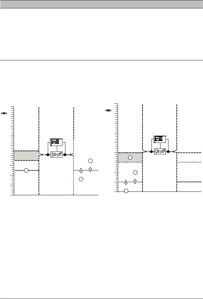
1) Demand Side or Forward Mode Pressure Control
 This is the Default, As Shipped, from the Factory Configuration
Used to accurately control Demand Side pressure (P4) system using air from the Supply Side (P3).This mode of operation is intended to ensure that a constant Demand or Outlet side pressure is maintained.
160 |
|
psi |
|
150 |
|
140 |
|
P3 |
P4 |
130 |
|
120 |
|
|
115 |
P3 |
Ao |
110 |
|
|
|
|
|
105 |
|
2 |
|
|
100 |
95 |
0% |
|
3 |
P4 Target = 95 |
||
|
|||
90 |
|
100% |
|
|
|
1 |
80
70
2) Supply Side / Back Pressure or Backward Mode Pressure Control
Used to protect the Inlet or Supply Side (P3) system from pressure decay due to excess air usage from the Demand Side (P4). This mode of operation is intended to ensure that a minimum specified Supply or Inlet side pressure is maintained.
160 |
|
psi |
|
150 |
|
140 |
|
P3 |
P4 |
130 |
|
120 |
|
|
|
|
|
|
P3 |
Ao |
|
110 |
110 |
|
110 |
|
|
|
|||
|
|
|
|
|
|
1 |
|
|
|
100 |
100 |
|
|
100 |
|
|
|
|
|
90 |
3 |
|
|
|
|
100% |
|
|
80 |
80 |
|
P3 Target = 80 |
||
|
|
|||
|
0% |
|
|
|
70 |
2 |
|
|
|
If P3 remains above 95psi (6.55 bar): P4 is maintained at P4 target:
If demand increases and P4 falls below 95psi (6.55 Bar): Valve opens towards 100% (1)
If demand decreases and P4 increases above 95psi (6.55 Bar):
Valve closes towards 0% (2)
If P3 falls below 95psi (6.55 Bar):
Valve will open 100% and P4 pressure will equal P3 pressure (3).
 The IX IntelliFlow is set to Fail Open by Default
If P3 remains above 80psi (5.51 bar):
Valve remains fully open and P4 pressure will equal P3 pressure (1).
If P3 falls to 80psi (5.51 bar):
P3 is protected from falling below 80psi:
If P3 falls below 80psi (5.51 bar): Valve closes towards 0% (2)
If P3 increases above 80psi (5.51 bar):
Valve opens towards 100% (3) and P4 pressure will equal P3 pressure.
 The IX IntelliFlow is set to Fail Open by Default. To change to Fail Closed, Please refer to Section 16
ingersollrandproducts.com
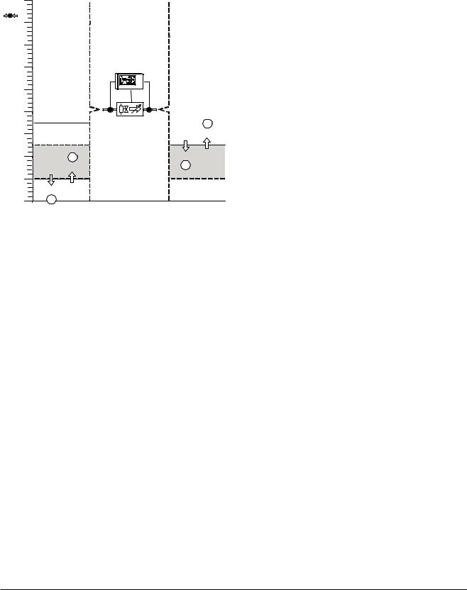
3) Combination Demand / Supply Side or Combination Mode Pressure Control
Used to accurately control pressure of the Demand Side pressure (P4) system using air from the Supply Side (P3) system while protecting the Supply Side (P3) system from pressure decay due to excess air usage from the Demand Side (P4) system
160 |
|
psi |
|
150 |
|
140 |
|
P3 |
P4 |
130 |
|
120 |
|
|
|
P3 |
Ao |
110 |
|
|
|
|
|
105 |
|
2 |
|
|
100 |
|
|
0% |
|
|
P4 Target = 95 |
|
90 |
4 |
|
100% |
|
100% |
|
1 |
|
|
80 |
|
80 |
|
P3 Target = 80 |
|
|
|
||
|
0% |
|
|
70 |
3 |
|
|
If P3 remains above 95psi (6.55 bar): P4 is maintained at P4 target:
If demand increases and P4 falls below 95psi (6.55 bar) Valve opens towards 100% (1)
If demand decreases and P4 increases above 95psi (6.55 bar):
Valve closes towards 0% (2)
If P3 falls below 95psi (6.55 bar) but remains above 80psi (5.51 bar):
Valve will open 100% and P4 pressure will equal P3 pressure.
If P3 falls to 80psi (5.51 bar):
P3 is protected from falling below 80psi (5.51 bar):
If P3 falls below 80psi (5.51 bar): Valve closes towards 0% (3)
If P3 increases above 80psi (5.51 bar): Valve opens towards 100% (4)
 The IX IntelliFlow is set to Fail Open by Default. To change to Fail Closed, Please refer to Section 16
ingersollrandproducts.com |
7 |

SECTION 6 - INSTALLATION
IX INTELLIFLOW TECHNICAL DATA
VALVE ASSEMBLY
•Available in 2” to 8” (50 to 200mm) configurations.
•Piping is A53, Grade B, Type E, Schedule 40 welded steel.
•Connections are ANSI / DIN Raised Face flanges and are design rated for 200 lb (13.87 Bar) ANSI / DIN.
•The valve body material is cast iron ASTM A126 Class B design.
•The valve stem material is 416 stainless Steel ASTM A582 Type 416 design.
•The valve seat material is bonded Buna-N Food Grade design.
•The valve disc material is Nylon 11 coated ductile iron ASTM A536 Gr.65-45-12 design.
•The valve has no field adjustments necessary to maintain optimum field performance.
•Inlet air temperature to valve not to exceed 150°F (66°C).
•Minimum control supply pressure (upstream of valve) of 80 PSIG (5.5 bar).
•Nominal pressure drop should not exceed 1 PSIG (0.06 bar) across entire assembly with valve fully open.
•The valve actuator is a direct mounted pneumatic, rack & pinion actuator with spring return.
•The valve positioner is a single acting type with visual digital indicator.
•The filter regulator assembly has a 5-micron rating. The Bowl is metal with an adjustment knob and a Sight Glass.
•An Assembly mounted PID Controller is standard.
•Control valve defaults open on loss of control signal to provide maximum security to process.
•Flow range on each size is based upon the ability of the valve to maintain +/- 1.0 PSIG (0.05 bar) tolerance at max. & min. flow conditions.
 Provided the application of a properly sized receiver tank for system storage.
•Taps: 1 upstream of the valve for control air and pressure transducer (P3), 1 downstream of the valve for the pressure gage and pressure transducer (P4), 1 upstream & 1 downstream of the valve for drain ports, 1 upstream & 1 downstream of the valve for field instruments.
•Assemblies are assumed to be installed in a building and thereby protected from the elements. Electrical enclosures are designed to meet the requirements for a NEMA 12 / IP54 rating. Assembly is CRN listed
•Ambient Operating Conditions: between 35°F and 115°F (2°C and 46°C), humidity from 0-95% noncondensing and inlet pressures not to exceed 200 PSIG (13.78 bar).
•Downstream set point should be at least 5 PSIG (0.3 bar) below minimum upstream pressure.
•Pressure turndown typically ≤ 30% maximum.
CONTROLLER ASSEMBLY
•Forward, backpressure and combination control
•4 Target Setpoints
•6 Remote Input Functions
o Select 1 of 3 Target Pressure Setpoints o Select Manual Mode
o Force Valve Open
oForce Valve Closed
•2 Output Relays – Configurable via Virtual Relay Programming
•Dual pressure sensors - one for Inlet Pressure (P3) and one for Outlet Pressure (P4)
•Modbus RTU communications capabilities
•Interfaces with a X8I or X12I system with Visualization
•Power supply input that will accept 100Vac to 240Vac, 50/60Hz
•Enclosure is NEMA 12 / IP54 rated
ingersollrandproducts.com
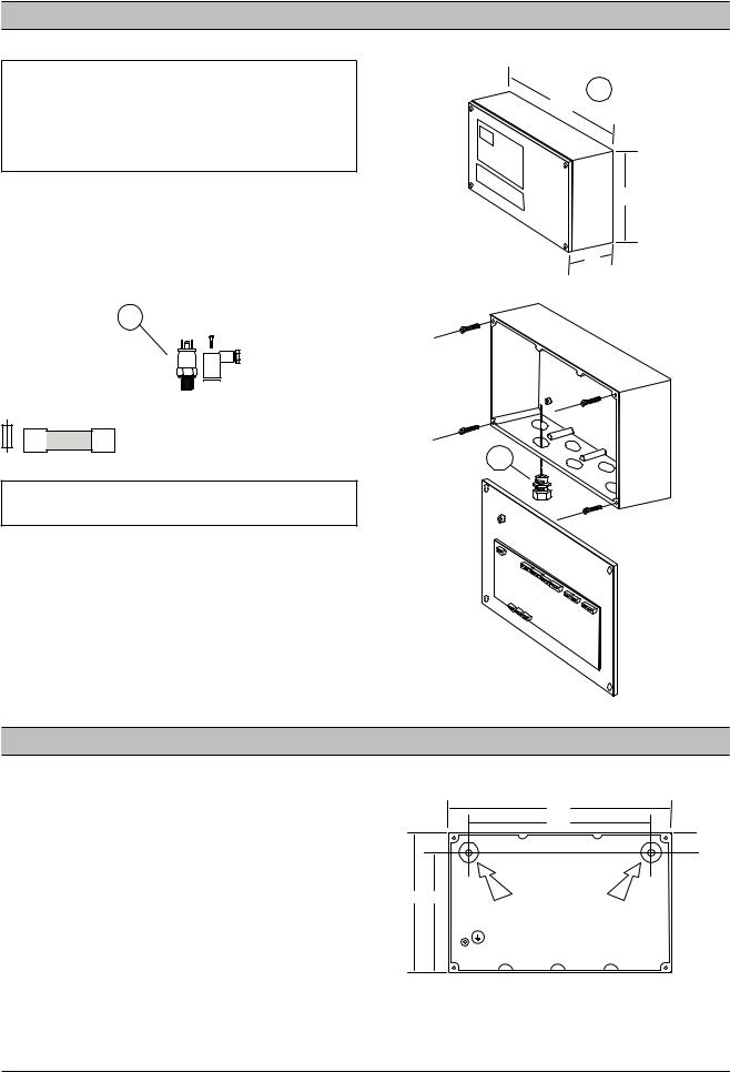
IX INTELLIFLOW INSTALLATION
The IX IntelliFlow controller unit has been tested for functionality and is ready for installation. Ingersoll Rand recommends that a no-loss drain valve (CCN 38445920) be installed on the condensate drain valve below the pressure transducer. (Other condensate drain mechanisms can be installed/used. Consult Technical Support or AfterMarket for assistance.) Inspect the unit upon receipt. Immediately report any damage to the shipping carrier.
FILTER INSTALLATION
The filter regulator assembly is shipped loose with the IX controller. The assembly is packaged in a box that is stored underneath the controller mounting bracket. Please remove and mount as shown below
(A). The control air line for the filter assembly should be connected to the tee fitting connected to P3 (B).
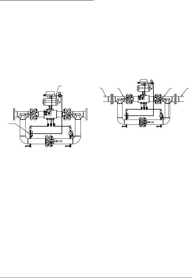
MOUNTING POSITION & SUPPORT
The unit can be installed in any plane and is capable of being installed vertically or horizontally. Additional
work is required when installing in the vertical mounting position.
Horizontal Mounting
The unit is to be supported appropriately taking into consideration the weight of the unit (reference the respective drawings in the diagrams section for approximate weights). Support should be provided through:
A.The main piping (A) of the unit (not the control elements, the associated control piping, or valve assemblies), and/or
B.The system piping (B).
A |
B |
A |
A |
B |
|
B
 It may be necessary to add a drain line to the control air filter to relieve buildup of condensate in the filter.
DIRECTION OF AIR FLOW
The unit has directional flow arrows. Orient the unit in accordance with the compressed air flow system. The factory unit is configured such that the air flows from left to right when looking at the controller display. There may be some cases when installing the IX IntelliFlow unit where the air flows from right to left placing the controller away from view. In these instances, re-mount the bracket supporting the controller enclosure to the opposite side of the IX IntelliFlow unit and rotate the pressure gauge 180 degrees. Then mount the IntelliFlow in the direction of the air flow (right to left). The air flow
will follow the air flow decals (entering on the P3 pressure transducer side).
•Consult Technical Support for further information.
•Wire the unit in accordance with the wiring schematic in the DIAGRAMS section of this manual. Incoming power should be connected via the Gland Holes using the necessary wire glands.
•Fix any loose pre-wired connections.
Vertical Mounting
For vertical mounting, the pressure transducers and the filtered pressure regulator are to be re-oriented 90˚.
•The pressure transducers must be re-oriented such that the body of the transducer is directed upwards. The sensor cable should be on top of the sensor.
•Additional elbows required to re-orient these devices shall be field supplied and installed.
oThe fittings must be rated for 200 PSI (13.78 Bar) minumum.
 It may be necessary to add a field installed drain connected at the bottom piping run to allow for proper drainage of condensate that may collect in the piping.
ingersollrandproducts.com |
9 |
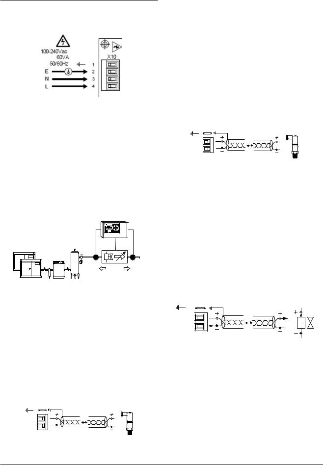
IX BOX POWER SUPPLY
The IX IntelliFlow Controller Unit is equipped with a power supply input that will accept 100Vac to 240Vac, 50/60Hz.
 Before applying power to the IX IntelliFlow Controller unit ensure that the power supply connections are correct and secure and that the supply voltage is 100Vac to 240Vac (+-10%), 50/60Hz.
 Wiring run through the enclosure must be made using Type 12 UL rated fittings which are field provided.
IX INTELLIFLOW VALVE CONTROLLER CONNECTION AND SENSOR ARRANGEMENT
The IX IntelliFlow assembly ships with both the P3 and the P4 pressure transducers installed and prewired to the IX controller inputs. The control valve positioner is also prewired to the controller output.
X 02 |
X01 |
X 03
Ao
P3 P4
P3 Supply Side, High Pressure Side (IX IntelliFlow Inlet) pressure transducer.
P4 Demand Side, Low Pressure Side (IX IntelliFlow Outlet) pressure transducer.
Ao Analog output to the IX Control Valve positioner.
 If it is necessary to remote mount the IX IntelliFlow controller, the following diagrams depict the electrical connections between the controller, the pressure transducers, and the control valve positioner.
P4 Pressure Sensor, 4-20mA: For Demand Side / Forward Mode Pressure Control (Factory Default) or Combination Demand / Supply Side / Combination Mode Pressure Control (Optional)
P4 
|
|
100m (330ft) max |
+C |
1 |
|
Ai1 |
2 |
|
|
X01 |
4-20mA |
Pressure Sensor ‘P4’ must be installed on the Low
pressure, Demand side or outlet side, of the IX IntelliFlow Valve assembly. Use shielded (earth screened), twoconductor (2 core), 20 gauge (0.5mm2 CSA) minimum, cable no greater than 330ft (100m) in length.
 Connection polarity is important.
 For ‘Backward’ mode it is not necessary to connect a ‘P4’ pressure sensor.
 For ‘Forward’ or ‘Combination’ Modes a ‘P4’ sensor must be connected.
 Re-use electrical fittings provided for pressure transducer wiring.
P3 Pressure Sensor, 4-20mA: For Supply Side / Back Pressure / Backward Mode or Combination Demand / Supply Side / Combination Mode Pressure Control.
P3 
|
|
100m (330ft) max |
+C |
1 |
|
Ai2 |
2 |
|
|
X02 |
4-20mA |
Pressure Sensor ‘P3’ must be installed on the High Pressure or inlet side, of the IX IntelliFlow Valve assembly. Use shielded (earth screened), two-conductor (2 core), 20 gauge (0.5mm² CSA) minimum, cable no greater than 330ft (100m) in length.
 Connection polarity is important.
 For ‘Forward’ mode it is not necessary to connect a ‘P3’ pressure sensor.
 For ‘Backward’ or ‘Combination’ Modes a ‘P3’ sensor must be connected.
 Re-use electrical fittings provided for pressure transducer wiring.
Valve Control Analog Output, 4-20mA: For Control of the Control Valve Positioner
|
|
100m (330ft) max |
A o |
1 |
|
A -GND 2 |
|
|
|
X03 |
4-20mA |
Connect the controller ‘Ao’ 4-20mA control output to the valve 4-20mA input. Use shielded (earth screened), twoconductor (2 core), 20 gauge (0.5mm2 CSA) minimum, cable no greater than 330ft (100m) in length.
The ‘Ao’ 4-20mA output is active at a voltage of 24VDC (+-2VDC) and is intended for connection to devices with a ‘loop powered’ 4-20mA input.
 Connection polarity is important.
 Re-use electrical fittings provided for pressure transducer wiring.
10 |
ingersollrandproducts.com |
IX BOX RS485 NETWORK
The IX IntelliFlow Valve Controller is equipped with an RS485 network communications capability using Modbus RTU or being connected to the X-Series compressor control products.
|
|
|
RS485 |
-L2 |
(B) |
1 |
-L2 (B) |
+L1 |
(A) |
2 |
+L1 (A) |
|
|
|
X13
Modbus RTU or IRBus/RS485
 The cable used should be Belden 9841 (or equivalent). It should be run in grounded conduit and should not be greater than 4000 feet (1219 meters) in length.
 Connection polarity is important.
 Wiring run through the enclosure must be made using Type 12 UL rated fittings which are field provided.
 Menus and Menu Items
 RS485 data communications and other low voltage signals can be subject to electrical interference. This potential can result in intermittent malfunction or anomaly that is difficult to diagnose. To avoid this possibility always use earth shielded cables, securely bonded to a known good earth at one end. In addition, give careful consideration to cable routing during installation.
a)Never route an RS485 data communications or low voltage signal cable alongside a high voltage or 3-phase power supply cable. If it is necessary to cross the path of a power supply cable(s), always cross at a right angle.
b)If it is necessary to follow the route of power supply cables for a short distance, attach the RS485 or signal cable on the outside of a grounded (earthed) cable tray such that the
cable tray forms a grounded (earthed) electrical interference shield.
c)Where possible, never route an RS485 or signal cable near to equipment or devices that may be a source of electrical interference (for example:
3-phase power supply transformer, high voltage switchgear unit, frequency inverter drive module, radio communications antenna).
ingersollrandproducts.com |
11 |

SECTION 7 - DISPLAY AND MENU OPERATION
Keypad:
a
e 
f |
b |
d  c
c
a)Reset
b)Menu
c)Enter
d)Down (Minus)
e)Up (Plus)
f)Escape (Cancel)
Display
Pressure = Main Display Pressure
% = Valve percentage open (0-100%)
The main display pressure is dependent on the Operating mode or the Combi. Mode Display Pressure (1.dP) setting. The Main Display Pressure will display the pressure value as follows:
Forward Mode = |
P4 Pressure |
Backwards Mode = |
P3 Pressure |
Combination Mode = |
menu 1.dP setting |
Manual Mode = |
menu 1.dP setting |

 Press UP or DOWN to view other user menu items.
The display will remain on the selected ‘User’ menu item indefinitely.
At power-up, or reset, the display will default to the first user menu list item.
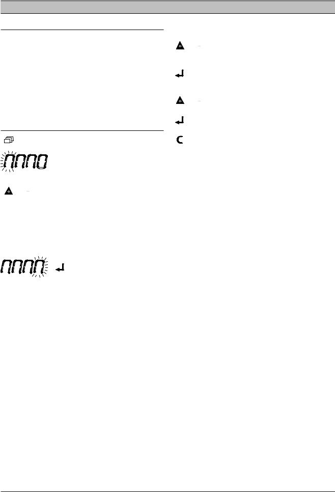
Status Symbols: |
|
ON/ON |
Operating |
ON/Flash |
Manual Mode |
Flash/OFF |
Forced Open/Closed |
OFF/OFF |
Fault Shutdown |
Flash |
Fault |
Status: |
|
B |
A |
‘A’ = Active Target Pressure Setting
1, 2, 3 or 4 (1 = default) Manual Mode = “-“(dash)
‘B’ = Mode
|
Forward Mode |
|
Backward Mode |
|
Combination Mode |
|
Manual Mode |
|
or Forced Closed |
|
or Forced Open |
i |
see ‘Status Symbols’ |
12 |
ingersollrandproducts.com |


 Press UP or DOWN to view other user menu items.
P3 High Pressure, Generation Side, Inlet:
 Only shown in ‘Forward’ mode if P3 sensor fitted.
P4 Low Pressure, Demand Side, Outlet:
 Only shown in ‘Backwards’ mode if P4 sensor fitted.
Active ‘High Target’ Pressure:
In accordance with the active target pressure H1, H2, H3 or H4
 Not shown in Forward or Manual Mode.
Active ‘Low Target’ Pressure:
In accordance with the active target pressure L1, L2, L3 or L4
 Not shown in Backwards or Manual Mode.
Valve Control Output (4-20mA):
Example: 12.0 Ao = 12.0mA, 50%
Network Address (IRBUS Mode):
B01 = Network I/O Box number
In IRBUS Mode the IX Box simulates a network I/O Box.
 For networks that have I/O Box(s) ensure the I/O Box number is unique.

 When the unit is detecting valid IRBUS communications from the XI management system unit the communications indicator symbol will show:
Network Address: Modbus Mode
Modbus Address – decimal 01 to 99
 The communications indicator symbol will not show in Modbus mode.
ingersollrandproducts.com |
13 |

SECTION 8 - COMMISSIONING
When commissioning the IX Box, carry out the following procedures before attempting to start.
 It is recommended that an authorized and trained service technician perform the commissioning.
PHYSICAL CHECKS
1.Before applying power to the IX Box, ensure the power supply connections are correct and secure (115Vac or 230Vac (+-10%), 50/60Hz).
2.Open the front panel of the IX Box and ensure all pressure sensor, RS485, and other connections are correctly installed and secure.
 See the section on Installation for more information.
3.Close the front panel of the IX Box.
4.Switch on the power supply to the IX Box.
5.The control program identification will be displayed for a short period followed by the normal operational user display.
PRESSURE DISPLAY
Check the displayed delivery pressure. If the pressure is incorrect, or inaccurate, check the type and range of the sensor and carry out the pressure sensor commissioning and calibration procedure.
3.3o P4 Outlet Pressure Offset
3.3r P4 Outlet Pressure Range
3.4o P3 Inlet Pressure Offset
3.4r P3 Inlet Pressure Range
 Menus and Menu Items
 Sensor Calibration Menu 3
OPERATING MODE
Set the operating mode for the IX Box to Forward Mode in the appropriate control menu:
1.oP Operating Mode
0:  Forward Mode
 This is the Default, As Shipped from the Factory, Configuration
Set the Tuning Parameters for Forward Control mode in the appropriate control menu:
1.3P P4 Proportional Pressure
Default is 20 1.3I P4 Integral Time
Default is 10
 Menus and Menu Items

 User Configuration Menu 1
PRESSURE SET POINTS
Set the Forward Mode Target pressure set point to suit system requirements in the appropriate control menu:
2.L1 Low Target Pressure #1  Menus and Menu Items

 Target Configuration Menu 2
IX BOX OPTIONAL FEATURES AND FUNCTIONS
Installation requirements may involve the implementation of additional or optional functions and features.
 As default, additional optional functions and features are deactivated or inhibited.
 Features and Functions; Menu Items
IX INTELLIFLOW START-UP
1.At initial start-up, begin with the bypass open.
2.Set the controller setpoint to a pressure at the bottom of the Existing Upstream pressure
bandwidth. This will provide a changing system to manually tune the control variables (proportional pressure and integral time) and verify stable control.  See the Setting the Tuning Parameters section for a description of how these values affect the control system.
3.Slowly close the bypass.
4.Monitor the system and validate stable control. If stable control is not achieved, open the bypass, adjust control variables, and return to step 3. Otherwise, continue to step 5.
5.Once stable control has been achieved, gradually lower the setpoint until the optimal value has been reached.
EXAMPLE:
Existing Upstream Pressure: 100-110 psi (6.9 to 7.6 bar) Critical Pressure (minimum): 85 psi (5.8 bar)
1.Begin with the bypass valve fully open.
2.Set the controller setpoint to 100 psi (6.9 bar).
3.Slowly close the bypass valve.
4.If the control is not stable (valve is overshooting the correct position or the setpoint is not being reached), open the bypass, adjust the control variables, and return to Step 3. If the control is stable, continue to step 5.
14 |
ingersollrandproducts.com |

5.Gradually lower the setpoint (pausing to verify that the control is still stable) until the optimal setpoint has been reached.
In this example, the optimal setpoint might be 90 psi (6.2 bar) with the downstream pressure fluctuating between 89.25 psi (6.1 bar) and 90.75 psi (6.25 bar) in regular operation. This would provide a 5 psi (0.3 bar) safety that would prevent the downstream pressure from going below 85 psi (5.8 bar) in the event of a sudden change in air demand or supply.
SETTING THE TUNING PARAMETERS
1.3P P4 Proportional Pressure
Default is 20 1.3I P4 Integral Time
Default is 10
PROPORTIONAL PRESSURE
Proportional control varies the signal sent to the valves as a linear response to the difference between the actual system pressure and the system pressure setpoint. Valve responsiveness can be adjusted through the IntelliFlow
Controller with the proportional pressure (1.3P.), setpoint.
This scaling factor is the amount of change in the input variable (actual minus setpoint pressures) to cause a full scale change in the output variable (valve position).
In other words, if the pressure in the air system fluctuates frequently, it would be prudent to set the proportional pressure to a low value (a value / number greater than the factory default of 20) to keep up with those system changes. Otherwise, if the system is very stable, it would be prudent to set the proportional pressure to a high value (a value / number less than the factory default
of 20) to keep up with those system changes. The proportional pressure is directly related to valve life and indirectly related to valve cycling; so, as band decreases, valve life decreases and cycling increases.
As stated earlier, the IntelliFlow Controller uses a proportional plus integral control algorithm. The result of proportional only control is offset from the controlled variable discharge pressure. This means that if the setpoint pressure is 100, the actual pressure may only be 95. The value of this offset depends upon the proportional pressure value.
What is the valve response when the difference between actual and setpoint pressures is zero? There is no response. Proportional control only functions when a difference or error exists. Design discharge pressure could not be attained in a proportional only control system. Therefore, an integral control algorithm is added to achieve the desired discharge pressure.
INTEGRAL TIME
The offset produced by the proportional control algorithm could be eliminated by manually readjusting the system pressure setpoint. Using the example above, the setpoint could be reset to 105 to obtain the 100 desired. Manually resetting the setpoint would be required as the system demand fluctuated. Integral control, also known as reset control, automatically resets the desired system pressure setpoint. For the IntelliFlow controller, the rate at which the controller resets the system pressure setting is known as Integral Time, (1.3I.), and is expressed in minutes between reset.
If precise control of the specified discharge pressure is required, the Integral Time setpoint should be set for a fast value. In other words, if the pressure in the air system fluctuates frequently, it would be prudent to set the Integral Time to a high value (a value / number greater than the factory default of 10) to keep up with those system changes. Otherwise, if the system is very stable, it would be prudent to set the Integral Time to a low value (a value / number less than the factory default of 10) to keep up with those system changes. It is directly related to valve life and inversely related to valve cycling, so, as Integral Time increases, the valve life increases and cycling decreases.
When band is low and Integral Time is fast, valve activity is significant in both magnitude and frequency to obtain the desired setpoint. The other scenario, band is high and Integral Time is slow, has relatively little valve activity, and may never reach the setpoint position.
Proportional pressure and Integral Time are variables used internally by the control system to determine valve response and direction for a given compressed air system. Each has an optimum value based upon the system’s characteristics. Determining these optimum
values is a trial and error exercise. These setpoints should be re-evaluated any time there is a major change in the compressed air system.
ingersollrandproducts.com |
15 |
SECTION 9 - SYSTEM CONFIGURATION
DISPLAY AND MENU OPERATION
All value, parameter or option selection displays are grouped into menu lists. Items are assigned to a list according to type and classification. Items that can be used to select options or modify functions are assigned to ‘menu mode’ lists. Items that a User may require to view during routine operation, detected pressure for example, are assigned to the normal operational mode list.
Each menu has a unique access code. Only one menu can be entered at a time.
ACCESSING THE IX CONFIGURATION SCREENS
 To access a menu press MENU.


 The display will show four “0” characters; the first character will flash.

 Press Up or Down to adjust the first character to match the first character of the required access code. If the access code number is ess than ‘1000’ the first character will be ‘0’. Press Enter to increment to the second code character.
 Menu codes are listed next to each Menu. See Configuration Menu Overview for codes


 When all four access code characters have been set, and the last code character is flashing, press Enter. If the access code is correct for
access to one of the accessible menus the first menu item of the appropriate menu will be displayed. If the access
code is incorrect the display will return to the normal operational display.

 To select a menu item for adjustment press Up or Down until the menu item is displayed.
 To adjust an item setting press Enter, the value or option will flash.

 Press Up or Down to adjust as required.
 Press Enter to store in memory.
 To exit the menu routine and return to the normal operational display, at any time, press Cancel. The display will return to the normal operational view. Any adjustment that has not be entered to memory will be abandoned and the previous setting maintained.
16 |
ingersollrandproducts.com |

CONFIGURATION MENU OVERVIEW
Each menu is accessed individually using the access codes show.

 User Configuration Menu 1
Menu Access Code ‘0011’
1. - -
1.oP Operating Mode
1.3P P4 Proportional Pressure
1.3I P4 Integral Time
1.4P P3 Proportional Pressure
1.4I P3 Integral Time
1.bA Backwards Mode Algorithm 1.Po Manual Mode %Open
1.SP Maximum %Change/Second 1.LP Valve %Open Low Level 1.HP Valve %Open High Level
1.SF Control Pressure Fault Response 1.CF Communication Fault Response 1.Ad Network Address
1.Pd Pressure Display Unit
1.dP Combi. Mode Display Pressure

 Target Configuration Menu 2
Menu Access Code ‘0021’
2. - -
2.L1 Low Target Pressure #1 (default)
2.H1 High Target Pressure #1 (default)
2.L2 Low Target Pressure #2
2.H2 High Target Pressure #2
2.L3 Low Target Pressure #3
2.H3 High Target Pressure #3
2.L4 Low Target Pressure #4
2.H4 High Target Pressure #4
 Sensor Calibration Menu 3
Menu Access Code ‘0031’
3. - -
3.3o P4 Outlet Pressure Offset
3.3r P4 Outlet Pressure Range
3.4o P3 Inlet Pressure Offset
3.4r P3 Inlet Pressure Range


 Relay Functions R1 to R6
Menu Access Code ‘0041’ (R1) to ‘0046’ (R6)
4. - -
4.F1 Input Function #1 (A, b and C)
4.F2 Input Function #2 (A, b and C) 4.Fu Logic Function
4.on On Delay Time 4.oF Off Delay Time 4.St Normal State
4.CF RS485 Failure Response
 Diagnostic Menu 5
Menu Access Code ‘0051’
5. - -
5.d1 Digital Input #1 (Di 1)
5.d2 Digital Input #2 (Di 2)
5.d3 Digital Input #3 (Di 3)
5.d4 Digital Input #4 (Di 4)
5.d5 Digital Input #5 (Di 5)
5.d6 Digital Input #6 (Di 6)
5.r1 Output Relay #1 (R1)
5.r2 Output Relay #2 (R2)
5.A1 Analog Input #1 (Ai1)
5.A2 Analog Input #2 (Ai2) 5.Ao Analog Output (Ao)
ingersollrandproducts.com |
17 |

USER CONFIGURATION MENU 1
1.oP – Operating Mode
There are 5 Operating Modes for the IX IntelliFlow control. 0:  Forward Mode
P4 pressure sensor (Outlet, Low pressure, Demand Side) is used for Control Pressure in accordance with active ‘Low Target’ (2.L1 to 2.L4) pressure set point. The ‘High Target’ (2.H1 to 2.H4) pressure set points are inhibited and any P3 pressure sensor fault is ignored.
The valve will regulate using the P4 pressure in accordance with the ‘1.4P’ proportional pressure and ‘1.4I’ integral time settings.
Forward Mode Control action is:
Target is 95psi (6.55 bar)
If P3 remains above 95psi (6.55 bar):
P4 is maintained at P4 target:
If demand increases and P4 falls below 95psi (6.55 Bar):
Valve opens towards 100%
If demand decreases and P4 increases above 95psi (6.55 Bar):
Valve closes towards 0%
If P3 falls below 95psi (6.55 Bar):
Valve will open 100% and P4 pressure will equal P3 pressure
This mode of operation is intended to maintain a constant Demand, or Outlet, side pressure where the Generation, or Inlet, is at a higher pressure level.
1:  Backward Mode
P3 pressure sensor (Inlet, High Pressure, Generation Side) is used for Control Pressure in accordance with active ‘High Target’ (2.H1 to 2.H4) pressure set point. The ‘Low Target’ (2.L1 to 2.L4) pressure set points are inhibited and any P4 pressure sensor fault is ignored.
If ‘1.bA = 0’:
The ‘1.4P’ (P4 Proportional Pressure) and ‘1.4I’ (P4 Integral Time) algorithm parameters are used.
If ‘1.bA = 1’:
The ‘1.3P’ (P3 Proportional Pressure) and ‘1.3I’ (P3 Integral Time) algorithm parameters are used.
The valve will regulate using the P3 (Inlet, High Pressure, Generation Side) pressure sensor in accordance with the applicable ‘Proportional’ pressure and ‘Integral’ time settings.
Backward Mode Control action is:
Target is 80psi (5.51 bar)
If P3 remains above 80psi (5.51 bar):
Valve remains fully open and P4 pressure will equal P3 pressure.
If P3 falls to 80psi (5.51 bar):
P3 is protected from falling below 80psi:
If P3 falls below 80psi (5.51 bar):
Valve closes towards 0%
If P3 increases above 80psi (5.51 bar):
Valve opens towards 100% and P4 pressure will equal P3 pressure.
This mode of operation is intended to ensure a minimum specified Generation, or Inlet, side pressure is maintained in instances where air demand from the Demand side, or Outlet, becomes excessive and Demand side pressure begins to decay.
2:  Combination Mode
Both the P4 (Outlet, Low pressure, Demand Side) and the P3 (Inlet, High Pressure, Generation Side) pressure sensors are used for control. The ‘Forward’ mode and ‘Backwards’ mode control algorithms operate together at the same time. Whichever control loop algorithm produces the lowest %Open value will take priority; the valve will follow the lowest %Open value.
In Combination mode, the operation and use of the valve is dependent on the relationship between the set ‘Low Target’ and ‘High Target’ pressure set points.
Backward Mode Control action is: P4 target is 95psi (6.55 bar)
P3 target is 80psi (5.51 bar)
If P3 remains above 95psi (6.55 bar):
P4 is maintained at P4 target:
If demand increases and P4 falls below 95psi (6.55 bar)
Valve opens towards 100%
If demand decreases and P4 increases above 95psi (6.55 bar):
Valve closes towards 0%
If P3 falls below 95psi (6.55 bar) but remains above 80psi (5.51 bar):
Valve will open 100% and P4 pressure will equal P3 pressure.
If P3 falls to 80psi (5.51 bar):
P3 is protected from falling below 80psi (5.51 bar):
If P3 falls below 80psi (5.51 bar):
Valve closes towards 0%
If P3 increases above 80psi (5.51 bar):
Valve opens towards 100%
3:  Manual Mode
The valve will open to the percentage open value specified in ‘1.Po’. The valve will remain fixed at this %Open value regardless of target pressure set points, variation in detected pressure, pressure sensor availability or sensor fault state condition.
18 |
ingersollrandproducts.com |

4:  Forced Closed
The valve is forced ‘Closed’. P3 and P4 pressure sensor faults are ignored. When ‘Force Closed’ is activated the valve will close immediately in accordance with the set ‘1.SP’ percent change per second limit. The ‘1.SP’ setting restricts how fast the valve will close.
5: 

 Forced Open
The valve is forced ‘Open’. P3 and P4 pressure sensor faults are ignored. When ‘Force Open’ is activated the valve will open immediately in accordance with the set ‘1.SP’ percent change per second limit. The ‘1.SP’ setting restricts how fast the valve will open.
1.3P P3 Proportional Pressure Factor
The pressure range, above and below the set ‘target’ pressure, where integral control will occur.
1.3I P3 Integral Time Factor
The time that the output will execute a full scale change from 4mA to 20mA, 0-100% (or vice versa).
1.4P P4 Proportional Pressure Factor
The pressure range, above and below the set ‘target’ pressure, where integral control will occur.
1.4I P4 Integral Time Factor
The time that the output will execute a full scale change from 4mA to 20mA, 0-100% (or vice versa).
1.bA |
Backwards Mode Algorithm |
0 - |
The ‘1.4P’ (P4 Proportional Pressure) and ‘1.4I’ |
|
(P4 Integral Time) algorithm parameters are used |
|
for ‘Backwards’ mode operation. |
1 - |
The ‘1.3P’ (P3 Proportional Pressure) and ‘1.3I’ (P3 |
|
Integral Time) algorithm parameters are used |
|
for ‘Backwards’ mode operation (default). |
1.Po Manual Mode %Open Value
Manual Mode %Open value (0 to 100%)  refer to ‘Manual Mode’ (1.oP)
1.SP %Change/Second
Restricts how fast the valve will open, or close, when pressure changes abruptly and/or a significant ‘Target’ pressure change is made. If the applicable, or predominate, target algorithm produces a change in
%Open that exceeds the ‘1.SP’ setting the change in valve
%Open is restricted to the maximum % change determined by the ‘1.SP’ setting until the required valve %Open position is reached.
The ‘1.SP’ setting is expressed in %Change per second where a setting of 20% will restrict any change to a maximum of 20%Open per second - the valve will change from fully open (100%Open) to fully closed (0%Open) in five seconds if the required %Open value changes from 100%Open to 0%Open abruptly.
 ‘1.SP’ is always active in all modes.
1.LP Valve %Open Low Level
If valve %Open < set ‘1.LP’; then Ai#3 ‘S’ state is set to ‘1’. Ai#3 ‘S’ state will return to ‘0’ if valve %Open >= ‘1.LP’.
This setting has no effect on valve operation or %Open position but can be used in local and/or system wide ‘Virtual Relay’ automation.
1.HP Valve %Open High Level
If valve %Open > set ‘1.HP’; then Ai#4 ‘S’ state is set to ‘1’. Ai#4 ‘S’ state will return to ‘0’ if valve %Open <= ‘1.HP’.
This setting has no effect on valve operation or %Open position but can be used in local and/or system wide ‘Virtual Relay’ automation.
1.SF Control Pressure Fault Response
If a fault with the ‘Control’ pressure sensor occurs, or any pressure sensor in Combination Mode:
0 - Manual Mode
1 - Force Valve Open (default)
2 - Force Valve Closed
1.CF Communications Fault Response
If a fault with network communications occurs: 0 – Continue normally (default)
1 – Force Valve Open
2 – Force Valve Closed
Only applicable in IRBUS Communications Mode; always ‘0’ (continue normally) in Modbus Mode.
1.Ad Network Address
Modbus:
01 to 99 decimal (0 to 63 Hex) IRBUS Mode:
b01 to b12 (I/O Box 1 to 12)
 IRBUS or Modbus mode is selected automatically dependant on set address.
1.Pd Pressure Display Units
0 – bar
1 - psi (default)
1.dP Combi. Mode Display Pressure
Determines if the P3 or P4 pressure is displayed as the ‘Main Display Pressure’ when operating in Combination mode.
0 – P4 (default)
1 – P3
ingersollrandproducts.com |
19 |

PRESSURE TARGET MENU 2
2.L1 Low Target Pressure #1 (default)
Normal default outlet side target pressure when no digital inputs are activated.
Active in ‘Forward’ and ‘Combination’ modes; not used for ‘Backwards’ mode.
2.H1 High Target Pressure #1 (default)
Normal default inlet side target pressure when no digital inputs are activated.
Active in ‘Backwards’ and ‘Combination’ modes; not used for ‘Forward’ mode.
2.L2 Low Target Pressure #2
Applicable when ‘Target Pressure Set 2’ digital input activated.
Active in ‘Forward’ and ‘Combination’ modes; not used for ‘Backwards’ mode.
2.H2 High Target Pressure #2
Applicable when ‘Target Pressure Set 2’ digital input activated.
Active in ‘Backwards’ and ‘Combination’ modes; not used for ‘Forward’ mode.
2.L3 Low Target Pressure #3
Applicable when ‘Target Pressure Set 3’ digital input activated.
Active in ‘Forward’ and ‘Combination’ modes; not used for ‘Backwards’ mode.
2.H3 High Target Pressure #3
Applicable when ‘Target Pressure Set 3’ digital input activated.
Active in ‘Backwards’ and ‘Combination’ modes; not used for ‘Forward’ mode.
2.L4 Low Target Pressure #4
Applicable when ‘Target Pressure Set 4’ digital input activated.
Active in ‘Forward’ and ‘Combination’ modes; not used for ‘Backwards’ mode.
2.H4 High Target Pressure #4
Applicable when ‘Target Pressure Set 4’ digital input activated.
Active in ‘Backwards’ and ‘Combination’ modes; not used for ‘Forward’ mode.
 If more than one digital input is activated the following priority will apply:
1: (highest priority) |
Force Closed |
2: |
Force Open |
3: |
Manual Mode |
4: |
Target Set #2 |
5: |
Target Set #3 |
6: (lowest priority) |
Target Set #4 |
SENSOR CALIBRATION MENU 3
3.3o P3 Pressure Sensor Offset
3.3r P3 Pressure Sensor Range
P3 pressure sensor (Inlet, High pressure, Generation Side) calibration settings.
 See ‘Pressure Sensor Calibration Procedure’ 3.4o P4 Pressure Sensor Offset
3.4r P4 Pressure Sensor Range
P4 pressure sensor (Outlet, Low pressure, Demand Side) calibration settings.
 see ‘Pressure Sensor Calibration Procedure’ Pressure Sensor Calibration Procedure:
1)Commissioning
Initially set the ‘Offset’ (minimum) to the minimum or lowest pressure value for the sensor. Set the ‘Range’ (maximum) to the maximum or highest value for the sensor.
For example:
If the pressure sensor is a 0 to 232psi (0 to 16.0bar) type set the ‘offset’ to 0psi (0bar) and the ‘Range’ to 232psi (16.0bar).
Execute the calibration procedure.
2)Calibration Procedure
a)Offset: Expose the sensor to atmosphere and adjust the ‘offset’ setting (if necessary) until the detected pressure display shows 0psi (0bar).
b)Range: Apply an accurately know pressure to the pressure sensor and adjust the ‘Range’ setting until the detected pressure display matches the applied pressure. An applied pressure equal too, or greater than, the nominal system working pressure is recommended.
 The detected pressure is displayed with the calibration menu item and will change to match the new calibration setting as the setting is adjusted.
 There is no need for the applied pressure to be static; it can be dynamic and changing. This enables calibration to be carried out on a fully operational system where changing system pressure can be accurately verified from another source.
 Correct pressure sensor set-up and calibration is critical for successful system operation. It is recommended that pressure sensor calibration is examined, and adjusted if necessary, annually or a pre-determined routine periodic basis.
RELAY CONFIGURATION MENU 4
 see ‘Virtual Relay Automation’
20 |
ingersollrandproducts.com |
SECTION 10 - DIAGNOSTICS
DIAGNOSTIC MENU 5
The IX IntelliFlow Controller is equipped with comprehensive diagnostic functions. Each input can be examined individually and each output can be manually activated or manipulated individually.
P2 Controller Diagnostics:
D1 |
Digital Input 1 |
|
|
D2 |
Digital Input 2 |
1: ON |
|
D3 |
Digital Input 3 |
|
|
D4 |
Digital Input 4 |
0: OFF |
|
D5 |
Digital Input 5 |
|
|
D6 |
Digital Input 6 |
|
|
------------------------------------------------------------- |
|||
R1 |
Relay Output 1 |
OFF |
|
R2 |
Relay Output 2 |
||
|
|||
|
|
ON |
|
-------------------------------------------------------------
A1 |
Analog Input 1 |
psi <> mA |
A2 |
Analog Input 2 |
psi <> mA |
-------------------------------------------------------------
Ao Analog Output 0.0 to 20.0mA
Relay Outputs:
Each relay output can be energised and de-energised manually by selecting the item. Use Up(plus) and Down(minus) to adjust and Enter.
Analog Inputs:
The item will alternate between the detected value and the electrical measurement on the controller input
terminals. An independent measuring device can be used to check the displayed electrical measurement.
A1: |
P4 Outlet Pressure, 4-20mA |
A2: |
P3 Inlet Pressure, 4-20mA |
Analog Output:
The analog output can be manually adjusted to any desired level. Press Enter then use Up (Plus) and Down (Minus) to adjust and Enter. The output will return to normal operational value upon menu exit.
Reset All Settings To Default:
Enter an Access Code of ‘9750’; do not press enter when the last character is flashing.
Press and hold CANCEL for 10 seconds; the controller will reset and all settings will be reset to default. All previous settings will be permanently lost.
ingersollrandproducts.com |
21 |

SECTION 11 - FAULT CODES
In the event of a IX IntelliFlow IX Box Fault, the IX Box display a fault code. The fault code becomes an item in the User operational display menu. If more than one active fault occurs each will be displayed as a separate
item in the operational User menu; press Up or Down to view all active fault codes or to view the normal status display.
Fault codes are separated in to A: Alarm (Warning) and E: Shutdown Trip.
Pressure Sensor Faults:
Reaction to a pressure sensor fault is dependent on the sensor and mode. If the pressure sensor is being used for ‘Control Pressure’, or the unit is in ‘Combination Mode’, the controller will shutdown.
If the sensor is not being used for ‘Control Pressure’, and the unit is not in ‘Combination Mode’, the sensor fault will be ignored and the associating pressure display will show “- - - -“ (dashes).
Fault Codes:
E0115 P4 Pressure Sensor Fault
E0125 P3 Pressure Sensor Fault
E0821 Short Circuit
Short Circuit condition detected on the main controller unit (digital inputs)
E0866 DC Power Supply Low Check voltage of main power supply.
E5000 Internal Memory Map Error
The unit’s controller has detected disruption to the internal operational memory storage (RAM). The integrity of the RAM memory contents is suspect; the controller must be reset to clear and re-map the memory. Renew the controller if this fault condition persists.
The controller’s main power supply must be removed and re-applied to reset this condition.
Remote XI Management System Fault Code Display:
When set for an I/O Box address (b01 to b12) the XI management system can be set to monitor the unit for fault conditions.
B’nn’57 ‘nn’ = IO Box number (01 to 12)
P4 Demand Side Pressure Sensor Fault when operating in Forward or Combination mode.
B’nn’58 ‘nn’ = IO Box number (01 to 12)
P3 Generation Side Pressure Sensor Fault when operating in Backwards or Combination mode.
B’nn’60 ‘nn’ = IO Box number (01 to 12) General Trip (Shutdown)
B’nn’ - - ‘nn’ = IO Box number (01 to 12) RS485 communications disruption or loss.
 When in IR485 mode, and connected to a network, the ‘B’ fault codes can be monitored and displayed by an XI system management unit. The ‘B’ codes do not show on the IntelliFlow display.
22 |
ingersollrandproducts.com |
SECTION 12 - IX INTELLIFLOW CONTROLLER PART LIST
IX Box
Item |
Part No. |
Description |
1 |
- |
23451966 |
IX IntelliFlow |
|
1 |
23451974 |
Unit, IX IntelliFlow |
253 |
|
|||
2 |
634067 |
Gland, Set - Pg13.5 |
|
- |
80445588 |
Manual, User CD |
|
ACCESSORIES:
Required For P3 and P4 System Pressure Transducers
Item |
Part No. |
Description |
3 |
634065 |
Sensor, Pressure – Quantity (2) |
|
|
4-20mA, 0-232 psi (0-16.0bar) |
160
90
3
|
20mm |
|
|
IEC |
5mm |
|
|
2 |
Item |
Part No. |
Description |
2 |
634104 |
IEC Fuse T1.6A |
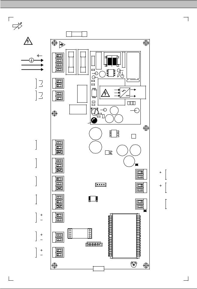
SECTION 13 - IX INTELLIFLOW CONTROLLER TECHNICAL DATA
IX Box Technical Data |
Mounting Dimensions (mm): |
Dimensions |
10” x 6.3” x 3.6” |
|
253 x 160 x 90mm |
Weight |
5.0lb (2.2kg) |
Mounting |
wall, 2 x screw fixings (8mm) |
Enclosure |
IP54, NEMA 12 |
Supply |
100 to 240Vac +/- 10% |
Power |
100VA |
Temperature |
32°F to 115°F (0°C to 46°C) |
Humidity |
95% RH, non-condensing |
|
253 |
|
24 |
205 |
24 |
24
A
160 136
ingersollrandproducts.com |
23 |
SECTION 14 - IX INTELLIFLOW CONTROLLER WIRING DIAGRAM
IR IntelliFlow Valv e |
|
|
|
|
|
Control UnitP2 |
|
|
|
|
|
|
|
|
|
IEC |
|
|
|
|
|
20 x 5mm |
|
100-240Vac |
X10 |
FH2 |
FH1 |
PSU |
|
60VA |
|
|
|
|
|
50/60Hz |
1 |
T1.6A |
T1.6A |
|
|
E |
2 |
|
|
||
N |
3 |
|
|
||
|
|
|
|
||
L |
4 |
|
|
|
|
R2 |
1 |
X09 |
|
|
|
2 |
|
|
|
||
|
|
|
|
|
|
|
|
|
|
E |
+VDC |
R1 |
1 |
X08 |
RL2 |
L |
0VDC |
2 |
|
N |
|||
|
|
|
|
|
|
|
|
|
RL1 |
|
|
|
|
|
LED1b |
|
|
|
+C |
+24VDC |
1 |
|
|
|
|
Di4 |
D4 |
2 |
X07 |
|
|
|
|
GND |
3 |
|
|
|
|
+C |
+24VDC |
1 |
|
|
LED2 |
|
Di3 |
D3 |
2 |
X06 |
|
|
|
|
GND |
3 |
|
|
|
|
+C |
|
|
|
|
X11 |
|
+24VDC |
1 |
X05 |
|
|
|
|
Di2 |
D2 |
2 |
|
|
|
|
|
|
|
|
|
|
|
|
GND |
3 |
|
C01 |
X12 |
|
|
|
|
|
|
|
|
+C |
+24VDC |
1 |
|
|
|
|
Di1 |
D1 |
2 |
X04 |
|
X13 |
|
|
GND |
3 |
|
|
|
|
|
|
|
|
||
|
Ao |
|
|
|
|
LED1 |
4-20mA |
|
1 |
X03 |
|
LCD |
|
A-GND |
|
2 |
|
|||
|
|
|
|
|||
|
|
|
|
X02 |
4-20mA |
|
|
|
|
|
Ai2 |
|
|
|
C |
|
1 |
|
|
|
|
|
|
ACM |
|
||
4-20mA |
Ai2 |
|
2 |
|
|
|
|
+C |
|
1 |
X01 |
C018 |
|
|
|
|
|
|||
4-20mA |
Ai1 |
|
2 |
|
|
|
|
|
|
|
|||
|
|
|
|
|
|
RT1 |
|
|
|
|
|
P2 |
|
2
1
2
1
2
1
D6
D5
RS485
+C
Di6
+C
Di5
+L1 (A) -L2 (B)
24 |
ingersollrandproducts.com |

IR IntelliFlow Valve |
|
|
|
|
|
|
|||||
Control Unit - P2 |
|
|
|
|
|
|
|
||||
P2 |
|
|
|
|
|
|
|
|
|
|
|
X13 |
|
-L2 (B) |
1 |
-L2 |
1 |
-L2 (B) |
|
|
|
|
|
|
|
|
|
|
|
|
|
|
|||
RS485 |
|
+L1 (A) |
2 |
+L1 |
2 |
+L1 (A) |
|
RS485 |
Modbus |
|
|
|
|
|
|
|
|
|
|
|
|||
|
|
+24VDC |
+C |
100m (330ft) max |
|
|
|
|
|||
|
|
1 |
|
|
|
|
|
||||
X01 |
|
|
|
1 |
|
|
|
|
|
|
|
|
Ai1 |
|
2 |
Ai1 |
2 |
4-20mA |
|
P4 |
Pressure |
|
|
|
|
|
|
|
|
|
|||||
|
|
|
|
|
|
|
|
|
Outlet |
|
|
|
|
|
|
|
|
|
|
|
Demand Side |
|
|
|
|
+24VDC |
+C |
100m (330ft) max |
|
|
|
|
|||
|
|
1 |
|
|
|
|
|
||||
X02 |
|
|
|
1 |
|
|
|
|
|
|
|
|
Ai2 |
|
2 |
Ai2 |
2 |
4-20mA |
|
P3 |
Pressure |
|
|
|
|
|
|
|
|
|
|
|
|
|
|
|
|
|
|
|
|
|
|
|
Inlet |
|
|
|
|
|
|
|
|
|
|
|
Supply Side |
|
|
|
|
Ao |
|
1 |
Ao |
100m (330ft) max |
|
|
|
|
|
X03 |
|
|
1 |
|
|
IntelliFlow Valve |
|
||||
|
A-GND |
2 |
A-GND 2 |
4-20mA |
Ao |
|
|||||
|
|
|
|
|
|
|
4-20mA Output |
|
|||
|
|
+24VDC |
+C |
|
|
|
|
|
|
||
|
|
|
|
1 |
|
|
|
|
|
|
|
X04 |
|
D1 |
|
2 |
Di1 |
|
Target 2 |
|
|
|
|
|
|
|
330ft (100m) max |
|
|
|
|
|
|||
|
|
0VDC |
|
3 |
GND |
|
|
|
|
|
|
|
|
|
|
|
|
|
|
|
|||
|
|
+24VDC |
+C |
|
|
|
|
|
|
||
|
|
|
|
1 |
|
|
|
|
|
|
|
X05 |
|
D2 |
|
2 |
Di2 |
|
Target 3 |
|
|
|
|
|
|
|
330ft (100m) max |
|
|
|
|
|
|||
|
|
0VDC |
|
3 |
GND |
|
|
|
|
|
|
|
|
|
|
|
|
|
|
|
|||
|
|
+24VDC |
+C |
|
|
|
|
|
|
||
|
|
|
|
1 |
|
|
Target 4 |
|
|
|
|
X06 |
|
D3 |
|
2 |
Di3 |
|
|
|
|
|
|
|
|
|
330ft (100m) max |
|
|
|
|
|
|||
|
|
0VDC |
|
3 |
GND |
|
|
|
|
|
|
|
|
|
|
|
|
|
|
|
|||
|
|
+24VDC |
+C |
|
|
|
|
|
|
||
|
|
|
|
1 |
|
|
|
|
|
|
|
X07 |
|
D4 |
|
2 |
Di4 |
|
Manual Mode |
|
|
|
|
|
|
|
330ft (100m) max |
|
|
|
|
|
|||
|
|
0VDC |
|
3 |
GND |
|
|
|
|
|
|
|
|
|
|
|
|
|
|
|
|||
|
|
|
|
|
|
|
|
|
|
|
|
|
|
|
|
1 |
|
|
|
|
|
|
|
X08 |
|
|
|
2 |
R1 |
|
|
|
|
|
|
X09 |
|
|
|
1 |
|
Virtual Relay |
240V CE' ' / 115V 'UL ' @ 4A |
|
|
|
|
|
|
|
2 |
R2 |
Configurable |
maximum. |
|
|
|
|
|
|
|
|
|
|
|
|
|
|
|
|
|
X11 |
|
D6 |
|
1 |
Di6 |
|
|
|
|
|
|
|
|
|
2 |
+C |
|
Force Open |
|
|
|
|
|
|
|
+24VDC |
|
|
|
|
|
|
|||
|
|
|
|
|
|
|
|
|
|||
|
|
|
|
|
Di5 |
330ft (100m) max |
|
|
|
|
|
X12 |
|
D5 |
|
1 |
|
|
|
|
|
|
|
|
|
|
2 |
+C |
|
Force Closed |
|
|
|
|
|
|
|
+24VDC |
|
|
|
X02 |
X01 |
||||
|
|
|
|
|
330ft (100m) max |
|
|
||||
|
|
|
|
|
|
|
|
|
|
|
|
1 |
2 |
3 |
4 |
|
|
|
|
|
|
X03 |
|
|
|
|
|
|
|
|
|
|
|
|
|
X10 |
|
|
|
|
|
|
|
|
P3 |
Ao |
P4 |
|
|
|
|
|
|
|
|
|
|||
|
E |
L N |
100 -240 Vac |
|
|
|
|
|
|
||
|
100VA |
|
|
|
|
|
|
||||
|
|
|
|
|
50/60Hz |
|
|
|
|
|
|
ingersollrandproducts.com |
25 |

ENCLOSURE MOUNTING
 1
1
2
 Use correct size Torrex Screw Driver
 A B
A B 
 A
A
B 
 See ‘Technical Data’ for enclosure and mounting dimensions.
 Excessive localized loading or force may fracture the enclosure:
1.Always use mounting washes provide.
2.Do not over tighten mounting fixtures.
 Cable Installation and Wire Connections:
 Invert and secure front panel to the rear enclosure lower front panel fixings.
26 |
ingersollrandproducts.com |

SECTION 15 - IX INTELLIFLOW CONTROLLER REMOTE INPUTS
IX BOX INPUT FUNCTIONS |
VIRTUAL RELAY AUTOMATION |
Remote ‘Volt-Free’ Switching Contact:
X04 |
|
|
+24V DC 1 |
|
|
|
|
+C |
T2 |
|
|
|
D1 |
2 |
|
|
|
|
Di1 |
||
|
|
|
|
|
|
|
||||
|
|
|
0V DC |
3 |
|
|
|
|
GND |
|
|
|
|
|
|
|
|
|
+C |
|
|
X05 |
|
|
+24V DC 1 |
|
|
|
|
T3 |
||
|
|
|
|
|
|
|||||
|
|
D2 |
2 |
|
|
|
|
Di2 |
||
|
|
|
|
|
|
|
||||
|
|
|
0V DC |
3 |
|
|
|
|
GND |
|
|
|
|
+24V DC 1 |
|
|
|
+C |
T4 |
||
|
|
|
|
|
|
|||||
X06 |
|
D3 |
2 |
|
|
|
|
Di3 |
||
|
|
|
|
|
|
|||||
|
|
|
0V DC |
3 |
|
|
|
|
GND |
|
|
|
|
|
|
|
|
|
+C |
|
|
|
|
|
|
|
|
|
|
|
|
|
|
|
|
+24V DC 1 |
|
|
|
M |
|||
X07 |
|
D4 |
2 |
|
|
|
|
Di4 |
||
|
|
|
|
|
|
|||||
|
|
|
0V DC |
3 |
|
|
|
|
GND |
330ft (100m) max |
X11 |
|
D6 |
1 |
|
|
|
|
Di6 |
||
|
|
|
|
|
FO |
|||||
|
|
|
|
|
||||||
|
+24V DC 2 |
|
|
+C |
||||||
|
|
|
|
|
|
|||||
X12 |
|
D5 |
1 |
|
|
|
|
Di5 |
FC |
|
|
|
|
|
|
||||||
|
+24V DC 2 |
|
|
+C |
||||||
|
|
|
|
|
|
|||||
Use 20 gauge (0.5mm² CSA) minimum, cable conductors no greater than 330ft (100m) in length.
T2: Target Pressure Set Points #2
T3: Target Pressure Set Points #3
T4: Target Pressure Set Points #4 M: Manual Mode
FO: Force Open
FC: Force Closed
Remote inputs are intended for remote activation from a ‘volt-free’ switching contact, relay contact, PLC or other remote logic device.
T2, T3 and T4:
When no ‘target pressure set’ digital inputs (Di1 to Di3) are activated the controller will use ‘Target Pressure Set #1’.
Remote Input Priority:
If more than one digital input is activated at the same time the following priority will apply:
1 (highest priority): |
Force Closed |
2: |
Force Open |
3: |
Manual Mode |
4: |
Target Set #2 |
5: |
Target Set #3 |
6: (lowest priority): |
Target Set #4 |
For example: |
|
If the ‘Force Open’ and ‘Target Set #3’ inputs are both activated together the unit will respond to the ‘Force Open’ input.
R1 |
1 |
|
2 |
|
|
|
|
|
|
|
X08 |
|
|
'CE' 240V @ 4A |
|
|
'UL' 115V @ 4A |
R2 |
1 |
Virtual Relay |
2 |
|
|
|
|
X09
The target pressure set (2, 3 or 4), manual mode or force closed/open selection inputs can also be activated by the IntelliFlow ‘Virtual Relay’ automation functions by connecting the appropriate ‘Virtual Relay’ output (R1 or R2) to the required digital input.
For example:
|
|
X07 |
M |
|
|
+24VDC |
1 |
|
|
|
|
|
|
|
|
||
D4 |
2 |
|
|
|
|
|
|
|
|
||
0VDC |
3 |
|
|
|
|
R1 |
1 |
|
|
|
|
|
|
|
|
||
|
|
|
|
||
|
|
|
|
||
2 |
|
|
|
|
|
|
|
|
|
|
|
|
|
|
|
|
|
|
|
X08 |
|
||
Virtual Relay output R1 (X08) will activate Manual Mode (X07).
Combinations of logic involving ‘Virtual Relay’ automation output(s) and remote switching ‘volt-free’ contact(s) of other third party devices can be implemented using this methodology.
ingersollrandproducts.com |
27 |

SECTION 16 - IX INTELLIFLOW CONTROLLER RS485 MODBUS REGISTERS
Modbus RTU Protocol @ 9600, N-8-1
Registers 400XX:
‘XX’ |
Item, Description |
01Status (R) Bits:
0 - Forward Mode
1 - Backwards Mode
2 - Combination Mode
3 - Manual Mode
4 - Forced Closed
5 - Forced Open
6 - Control Sensor Fault
7 - General Fault Shutdown (including control sensor fault)
02 P4 Outlet Pressure, psi (R)
03 P3 Inlet Pressure, psi (R)
04 Valve %Open x 100
0 to 10000 = 0 to 100% (R)
05 Ao - mA x 100
400 to 2000 = 4.0 to 20.0mA (R)
06Mode (R/W)
0 - Forward Mode
1 - Backward Mode
2 - Combination Mode
3 - Manual Mode
4 - Force Closed
5 - Force Open
07 L1: Low Target #1, psi (R/W)
08 H1: High Target #1, psi (R/W)
09L2: Low Target #2, psi (R/W)
10H2: High Target #2, psi (R/W)
11L3: Low Target #3, psi (R/W)
12H3: High Target #3, psi (R/W)
13L4: Low Target #4, psi (R/W)
14H4: High Target #4, psi (R/W)
153P - P4 Proportional Pressure mBar; 69mBar = 1psi (R/W)
163I - P4 Integral Time; secs (R/W)
174P - P3 Proportional Pressure (R/W) mBar; 69mBar = 1psi (R/W)
184I - P3 Integral Time; secs (R/W)
19BA - Backwards Mode Algorithm (0=3P/3I; 1=4P/4I) (R/W)
20SP - Maximum %Change/Second 100 to 10000 = 1% to 100% (R/W)
21LP - Valve %Open Low Level
0 to 10000 = 0% to 100% (R/W)
22HP - Valve %Open High Level 0 to 10000 = 0% to 100% (R/W)
23SF - Control Sensor Fault (R/W) 0 - manual mode
1 - force valve open
2 - force valve closed
24CF - Comms Fault (R/W) 0 - continue operating 1 - force valve open
2 - force valve closed
25Manual Mode %Open value, ‘Po’ 0 to 10000 = 0% to 100% (R/W)
(R)= Read Only
(R/W) = Read/Write
Read - function 03Hex
“01 03 00 00 00 01” Status Register
 ‘XX’ Register address has a ‘1’ offset:
For ‘Status’ (register address 01) use Hex address “00 00”
Write - function 06Hex only (single register) “01 06 00 05 00 02” set Mode to Combination
 ‘XX’ Register address has a ‘1’ offset:
For ‘Mode’ (register address 06) use Hex address “00 05”
 Mode - Write:
If the ‘P4’ sensor is not fitted, or in a fault state, the controller will not accept a command to change to ‘Forward’ or ‘Combination’ modes; a Modbus exception response will be returned.
If the ‘P3’ sensor is not fitted, or in a fault state, the controller will not accept a command to change to ‘Backwards’ or ‘Combination’ modes; a Modbus exception response will be returned.
28 |
ingersollrandproducts.com |

SECTION 17 - IX INTELLIFLOW DIGITAL POSITIONER
 The Digital I/P Positioner comes from the factory pretested and fully calibrated and should not require recalibration on new installations.
If the unit appears to need recalibration, please check all pipe fittings and connections for air leaks prior to performing the following calibration procedure.
IX INTELLIFLOW DIGITAL POSITIONER SETUP PROCEDURE
Overview
• Bray Series 6A (single-acting: only one output pressure)
ingersollrandproducts.com |
29 |

Feedback Angle Dial
•Set to 90˚
o Rotate yellow outside c-ring clockwise until center-mark is aligned with 90˚.
oThe sticker below the dial indicates the correct position for 90˚.
Transmission Ratio Push-Bar
•Set to 90˚
o Push the Bar upwards from the bottom of the unit.
oThe sticker on top, by the display, indicates the correct position for 90˚.
30 |
ingersollrandproducts.com |
Loading...