


Ingersoll Rand
System Automation
VSD mA Box
Instruction Manual
Before installing or starting this unit for the first time, this manual should be studied carefully to obtain a working knowledge of the unit and or the duties to be performed while operating and maintaining the unit.
RETAIN THIS MANUAL WITH UNIT. This Technical manual contains IMPORTANT SAFETY DATA and should be kept with the unit at all times.
More Than Air. Answers.
Online answers: http://www.air.irco.com
C.C.N. : 80444128 REV. : C
DATE : MARCH 2009
Section 1 - TABLE OF CONTENTS
Section 1 - TABLE OF CONTENTS.............................. |
3 |
Section 2 - InTRODUCTION....................................... |
4 |
Section 3 - Safety....................................................... |
4 |
INSTALLATION.............................................................................. |
4 |
OPERATION .................................................................................. |
4 |
MAINTENANCE AND REPAIR.................................................. |
4 |
Section 4 - COMPRESSOR CONNECTION AND |
|
CONTROL.......................................................................... |
5 |
COMPRESSOR CONNECTION AND CONTROL................. |
5 |
STANDARD CONTROL FEATURES AND |
|
FUNCTIONALITY......................................................................... |
5 |
VSD BOX OPERATION................................................................ |
6 |
Section 5 - INSTALLATION.......................................... |
7 |
UNIT LOCATION........................................................................... |
7 |
POWER SUPPLY........................................................................... |
7 |
RS485 NETWORK......................................................................... |
7 |
PRESSURE SENSOR CONNECTIONS.................................... |
8 |
VSD AND ir-PCB COMPRESSOR CONNECTIVITY........... |
9 |
ir-PCB COMPRESSOR CONTROL.......................................... |
9 |
ir-PCB COMPRESSOR STATUS MONITORING.................. |
9 |
READY.............................................................................................. |
9 |
RUNNING.................................................................................... |
10 |
LOADED....................................................................................... |
10 |
Section 6 - VSD BOX HARDWARE |
|
CONFIGURATION......................................................... |
12 |
Section 7 - INGERSOLL RAND TO VSD BOX |
|
INTERCONNECT........................................................... |
13 |
Section 8 - COMMISSIONING................................. |
15 |
Section 9 - DISPLAY AND MENU OPERATION..... |
17 |
Menu Navigation ............................................................... |
17 |
Section 10 - DIAGNOSTICS..................................... |
22 |
Section 11 - OPERATION.......................................... |
23 |
Keypad........................................................................................ |
23 |
Display....................................................................................... |
23 |
Indicators............................................................................... |
23 |
User Menu Items.................................................................. |
24 |
Power Failure Auto-Restart....................................... |
24 |
section 12 - Parts List........................................... |
25 |
|
IR VSD Box................................................................................. |
25 |
|
section 13 |
- Technical Data............................... |
25 |
VSD Box...................................................................................... |
|
25 |
section 14 |
- Wiring Diagram.............................. |
26 |
section 15 |
- commissioning form................... |
28 |
|
Refer to Section Indicated |
|
|
Note |
|
|
Important or Caution, Safety |
|
Section 2 - InTRODUCTION
The VSD Box is intended to provide a method of system integration for a VSD (Variable Speed Drive) air compressor that is not equipped with any accessible means of remote connectivity (such as the Ingersoll
Rand Nirvana). The VSD Box will provide the required functionality to enable system integration and efficient control using the X8I Automation System.
Section 3 - Safety
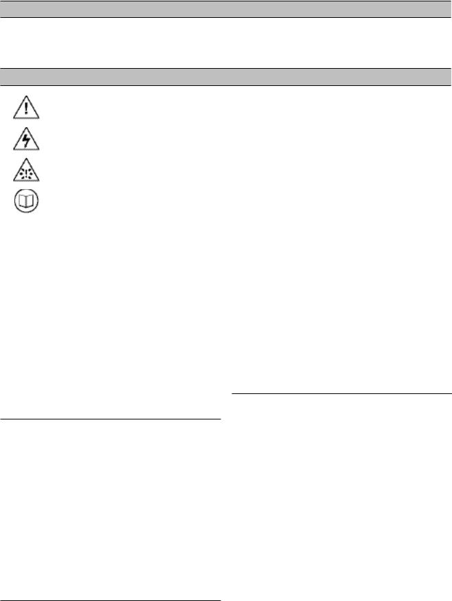
WARNING : Risk of Danger
WARNING : Risk of Electric Shock
WARNING : Risk of High Pressure
WARNING : Consult Manual
•Before installing or operating the VSD BOX, take time to carefully read all the instructions contained in this manual, all compressor manuals, and all manuals of any other peripheral devices that may be installed or connected to the unit.
•Electricity and compressed air have the potential to cause severe personal injury or property damage.
•The operator should use common sense and good working practices while operating and maintaining this system. All applicable codes should be strictly adhered to.
•Maintenance must be performed by adequately qualified personnel that are equipped with the proper tools.
INSTALLATION
•Installation work must only be carried out by a competent person under qualified supervision.
•A fused isolation switch must be fitted between the main power supply and the VSD BOX.
•The VSD BOX should be mounted in such a location as to allow operational and maintenance access without obstruction or hazard and to allow clear visibility of indicators at all times.
•If raised platforms are required to provide access to the VSD BOX, they must not interfere with normal operation or obstruct access. Platforms and stairs should be of grid or plate construction with safety rails on all open sides.
OPERATION
•The VSD BOX must only be operated by competent personnel under qualified supervision.
•Never remove or tamper with safety devices, guards or insulation materials fitted to the VSD BOX.
•The VSD BOX must only be operated at the supply voltage and frequency for which it is designed.
•When main power is switched on, lethal voltages are present in the electrical circuits and extreme caution must be exercised whenever it is necessary to carry out any work on the unit.
•Do not open access panels or touch electrical components while voltage is applied unless it is necessary for measurements, tests or adjustments. Such work should be carried out only by a qualified electrician equipped with the correct tools and wearing appropriate protection against electrical hazards.
•All air compressors and/or other equipment connected to the unit should have a warning sign attached stating ‘THIS UNIT MAY START WITHOUT WARNING’ next to the display panel.
•If an air compressor and/or other equipment connected to the unit is to be started remotely, attach two warning signs to the equipment stating ‘THIS UNIT CAN BE STARTED REMOTELY’. Attach one sign in a prominent location, one on the outside of the equipment, and the other inside the equipment control compartment.
MAINTENANCE AND REPAIR
•Maintenance, repairs or modifications must only be carried out by competent personnel under qualified supervision.
•If replacement parts are required use only genuine parts from the original equipment manufacturer, or an alternative approved source.
•Carry out the following operations before opening or removing any access panels or carrying out any work on the VSD BOX:
i.Isolate the VSD BOX from the main electrical power supply. Lock the isolator in the ‘OFF’ position and remove the fuses.
ii.Attach a label to the isolator switch and to the unit stating ‘WORK IN PROGRESS - DO NOT APPLY VOLTAGE’. Do not switch on electrical power or attempt to start the VSD BOX if such a warning label is attached.
•Make sure that all instructions concerning operation and maintenance are strictly followed and that
the complete unit, with all accessories and safety devices, is kept in good working order.
•The accuracy of sensor devices must be checked on a regular basis. They must be calibrated when acceptable tolerances are exceeded. Always ensure any pressure within the compressed air system is safely vented to atmosphere before attempting to remove or install a sensor device.
•The VSD BOX must only be cleaned with a damp cloth, using mild detergents if necessary. Avoid the use of any substances containing corrosive acids or alkalis.
•Do not paint the control faceplate or obscure any indicators, controls, instructions or warnings.
Section 4 - COMPRESSOR CONNECTION AND CONTROL
COMPRESSOR CONNECTION AND CONTROL
The VSD BOX is designed to connect to an X8I Automation System unit, using a 2-wire RS485 data cable.
The VSD Box is intended to provide a method of system integration for the Ingersoll Rand Bolt-On VSD’s as well as other 3rd party air compressors that are not equipped with any accessible means of remote connectivity.
Each air compressor in a system that requires VSD Box integration must be equipped with an individual VSD Box. Any number of VSD Boxes can be connected to the Automation System unit as long as the total number
of compressors does not exceed the total number of compressors for the Automation System model.
In conjunction with a ‘speed monitoring kit’ (available separately) the VSD Box will provide all required functionality to maximize the ENER, energy control mode, in the X8I or X12I Automation System
STANDARD CONTROL FEATURES AND FUNCTIONALITY
The Bolt-On VSD or the VSD equipped air compressor must be equipped with a 4-20mA pressure sensor or a 0.5V to 4.5VDC a pressure sensor that is used for variable speed drive regulation or compressor pressure regulation control. A VSD Box will accommodate a pressure sensor range of 14.5 psi (1.0bar) to 8702 psi (600bar).
Various Compressor Configurations and Characteristics Can Be Accommodated by the VSD Box. These include:
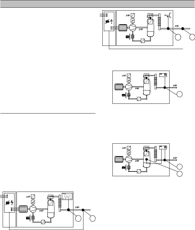
1)Bolt-On VSD air compressors that are equipped with two pressure sensors (1 and 2) that both monitor package discharge pressure. One sensor is dedicated to the compressor control system for load/unload regulation functions and the other pressure sensor is dedicated to the VSD for variable speed drive regulation.
1 2
2)Bolt-On VSD air compressors that are equipped with a package discharge pressure switch (1) dedicated to the compressor control system for load/unload regulation and a pressure sensor (2) dedicated to the VSD for variable speed drive regulation.
1 2
3)3rd party integrated VSD air compressors that are equipped with a single package discharge pressure sensor (1).
4)3rd party integrated VSD air compressors that are equipped with a package discharge pressure sensor
(1) and a second internal pressure sensor (2). The internal pressure sensor is generally used for internal air/oil filtration differential pressure monitoring and/ or internal pressure safety functions.
1
2
NOTE: There are VSD air compressors that are unable to maintain maximum speed operation for a prolonged
period of time. In these instances, the compressor control system may automatically reduce speed regardless
of demand. The VSD Box and Automation System will recognize this, and if necessary, utilize an additional compressor to meet demand.
NOTE: There are VSD air compressors that are unable to maintain minimum speed operation for a prolonged
period of time. In these instances, the compressor control system may automatically stop the compressor regardless of demand. The VSD Box will recognize and accommodate this behavior. The Automation System will indicate and record the compressor status correctly without fault indication.

VSD BOX OPERATION
All air compressors are equipped with a method of sensing pressure. An air compressor regulates using the compressor package discharge pressure as the control variable.
The VSD Box monitors the compressor pressure sensor as an input and simulates the pressure sensor signal as an output. The VSD Box uses this method to modify the pressure signal and manipulate the behavior of the air compressor. In other words, the VSD Box becomes the air compressor pressure sensor. This functionality enables the Automation System unit to utilize the compressor effectively and optimize total system efficiency and maintain air quality.
The VSD Box also monitors compressor status (Ready, Run, and Load/Unload) and continuously reports this information to the Automation System unit. This function enables the VSD Box to simulate all features of a standard X8I or X12I network compressor integration.
Actual System pressure and the Automation System ‘target’ pressure information is routinely transmitted from the X8I or X12I to the VSD Box. The VSD Box uses this information to calculate the difference between the compressor discharge pressure and the system ‘target’ pressure. The VSD Box utilizes pressure signal
manipulation to continuously re-align compressor output with system requirements.
This functionality also enables the VSD Box to continuously compensate for any pressure differential that may occur across local air treatment, along air pipe work or between different locations in a compressed air network.
From VSD Box
To ir-PCB
To Intellisys Controller
From Pressure Transducer |
To VSD Box |
From VSD Box |
To IR-5000 Pressure Transducer Input |
From VSD Box
To ir-PCB
To 1PS Pressure Switch
From Pressure Transducer |
To VSD Box |
From VSD Box |
To IR-5000 Pressure Transducer Input |
Section 5 - INSTALLATION
It is recommended that installation and commissioning be carried out by an authorized and trained product supplier.
UNIT LOCATION
The VSD Box is wall mounted using conventional screws/ bolts. The maximum distance between the X8I or X12I and the VSD Box is 4000ft (1219 meters) of cable length. The maximum distance between the VSD Box and
each compressor is 330ft (100 meters) of cable length and within 330ft (100 meters) of cable length from any pressure sensor option (if applicable)..
POWER SUPPLY
A fused switching isolator must be installed to the main incoming power supply, external to the VSD Box. The isolator must be fitted with a properly sized fuse to provide adequate protection to the power supply
cable used (in accordance with local electrical and safety regulations).
XPM-TAC24
1 |
2 |
3 |
4 |
1 |
2 |
3 |
4 |
|
|
|
|
X04 |
|
|
|
N |
L |
E |
E |
VOLTAGE SELECT |
|||
N L E |
X01 |
|
|
|
230Vac |
||
|
1 |
2 |
3 |
4 |
|||
|
|
|
|
||||
|
|
|
|
X04 |
|
|
|
VOLTAGE SELECT
115Vac
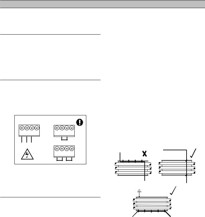
Power Supply Terminals
 Ensure that the voltage select input is properly jumpered for the incoming power. Default voltage configuration is 230Vac.
RS485 NETWORK
The VSD Box is equipped with an RS485 network communications capability using the ir485 protocol. The VSD Box is intended to operate as part of the X8I or X12I Automation System. Connection to the system management unit is two-wire, twisted pair, earth shielded, RS485 data link. Connect the RS485 data cable wires to terminal X07 located on the VSD Box ‘S1’ controller.
Note: Polarity is important.
 The cable used between the X8I and the VSD Box is Belden 9841 (or equivalent). It should be run in grounded conduit and should not be greater than 4000 feet (1219 meters) in length.
 RS485 data communications and other low voltage signals can be subject to electrical interference. This potential can result in intermittent malfunction
or anomaly that is difficult to diagnose. To avoid this possibility always use earth shielded cables, securely bonded to a known good earth at one end. In addition, give careful consideration to cable routing during installation.
a.Never route an RS485 data communications or low voltage signal cable alongside a high voltage or 3- phase power supply cable. If it is necessary to cross the path of a power supply cable(s), always cross at a right angle.
b.If it is necessary to follow the route of power supply cables for a short distance (for example: from a compressor X8I to a wall along a suspended cable tray) attach the RS485 or signal cable on the outside of an earthed cable tray such that the cable tray forms an earthed electrical interference shield.
c.Where possible, never route an RS485 or signal cable near to equipment or devices that may be a source of electrical interference (for example: 3-phase power supply transformer, high voltage switchgear unit, frequency inverter drive module, radio communications antenna).
PRESSURE SENSOR CONNECTIONS
 Consult the X8I Interconnect and Application Guide prior to the installation of the VSD Box to the pressure sensor on the VSD and the compressor.
Pressure sensor connectivity is dependant on compressor and control system type.
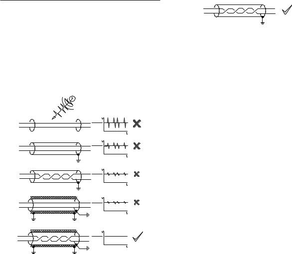
 Electrical Interference
0.5 to 4.5VDC Pressure Sensors
Voltage sensors and cables carrying low voltage analog signals are highly susceptible to interference.
 Always use shielded, braided, foil wrapped with a drain wire, 18 AWG maximum, 2-conductor cable no more than 330 feet (100 meters) in length. Ensure the braided steel wire is securely connected to a known good earth ground at both ends. Ensure the internal drain wire is securely connected to a known good earth ground at the VSD Box end only.
Failure to protect low voltage pressure signals between the compressor and VSD Box will result in unstable and/or erratic pressure readings; resulting in unstable and/or erratic compressor regulation behavior.
4 to 20mA Pressure Sensors
 Always use shielded, 18 gauge, 2-conductor cable no more than 330 feet (100 meters) in length. Ensure the shield wire is securely connected to earth ground at the VSD Box end only.
VSD AND ir-PCB COMPRESSOR
CONNECTIVITY
An ir-PCB is a requirement for a VSD Box installation.
The ir-PCB is a DIN rail mountable unit designed to be installed within the compressor control or switchgear area and connected to the VSD Box using a six-wire cable.
The ir-PCB is used for compressor status monitoring and in some installations, for remote load/unload or pressure switch regulation control.
 Consult the X8I Interconnect and Application Guide prior to the installation of the VSD Box and the ir-PCB to the air compressor.
C01 |
|
C02 |
|
C04 |
|||
|
ir-PCB |
|
#1 |
||||
|
|
C03 |
|
|
|
C05 |
|
V |
1 |
2 |
3 |
4 |
5 |
6 |
|
|
|
|
|
|
|
|
LED 1LED 2 |
|
|
|
|
|
X01 |
1 |
2 |
3 |
4 |
5 |
6 |
The ir-PCB uses a 12V to 250V ac/dc input voltage detection system and universal relay contact control outputs (250Vac/dc @ 5A maximum). Integrated directly into the circuits of an air compressor, the ir-PCB avoids the need for additional relays or remote inputs. The ir-PCB also acts as an electrical barrier between the compressor and the VSD Box providing protection and voltage isolation.
ir-PCB COMPRESSOR CONTROL
 Consult the X8I Interconnect and Application Guide prior to the installation of the VSD Box and the ir-PCB to the air compressor.
When connecting to an VSD, the VSD Box will control the ir-PCB load/unload relay outputs (terminals C01 and C02) in accordance with the VSD Box load and unload pressure set points. The ir-PCB load/unload relay contacts can be used for compressor that have pressure switch load/ unload regulation as well as those that have digital inputs for load/unload regulation.
ir-PCB COMPRESSOR STATUS MONITORING
 Consult the X8I Interconnect and Application Guide prior to the installation of the VSD Box and the ir-PCB to the air compressor.
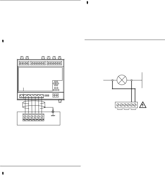
The ir-PCB is fitted with a six-pin terminal C04 for compressor monitoring. The ir-PCB uses three inputs (Ready, Run and Loaded) to determine compressor status. All three status-monitoring input signals are required.
READY
The ‘Ready’ connection is intended to indicate that the compressor is in a ‘started’ state, has no operational inhibiting fault condition and is ready to respond to VSD Box regulation without manual intervention.
Ready Input
READY LAMP |
0V |
+V
ALARM RUN READY
C04
The READY input will accept 12V to 250V ac (50/60Hz) or dc.
Caution: Do not connect a voltage greater than 250Vac/ dc to this input.
This input must be connected to the terminals of a ‘ready’ or ‘operational’ lamp, or other circuit of the compressor control system, that will be energized when the compressor is in started (standby or running) condition.
The voltage to this input must de-energize when the compressor is stopped and unavailable to produce air upon a load signal or the Emergency Stop button is pressed or when the compressor experiences a fault that prevents the compressor from running.
When the compressor ready lamp, or other control circuit, is energized the ir-PCB will detect the voltage and signal the VSD Box that the compressor is ready and available to load and produce air when a load request signal is given
Note: The ir-PCB input common terminal must always be connected to the neutral, common or 0V line of the applied input.
Ready Input, Alternative Connection Method:
In instances where a convenient voltage signal for a compressor ready condition is not available the ‘Ready’ input can be connected directly to a constant compressor control system power supply voltage (12V to 250Vac or dc). This will signal the VSD Box that the compressor is ready and available at all times when power is applied
to the compressor. The VSD has a built-in function to determine when a compressor is not responding, or is in a shutdown condition, regardless of a constant ready signal. If the VSD Box requests a compressor to run/load, but fails to detect a RUN signal within 60 seconds, the VSD Box will regard the compressor as ‘not ready’ and
indicate the compressor as not available. If a RUN signal is detected at any time, the VSD Box will automatically reset the compressor ‘not ready’ condition and re-establish control.
+Vac
F1
0Vac
READY
Safety: Never connect the READY input positive connection directly to the output of a control system transformer; always connect after a fuse or circuit breaker.
If a normally closed contact of an Emergency Stop button is included in the compressor power supply circuit, connect after the Emergency Stop button contacts. This will instantly indicate a compressor ‘not ready’ condition if the Emergency Stop button is activated
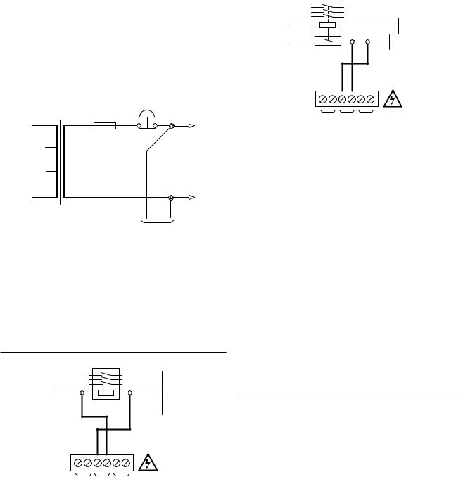
RUNNING
MAIN (LINE) CONTACTOR
0V
+V
ALARM RUN READY
C04
The RUN input will accept 12V to 250V ac (50/60Hz) only (DC can not be used).
Caution: Do not connect a voltage greater than 250V to this input.
12V to 250Vac must be applied to the ‘Run’ terminals when the compressor motor is running.
For a fixed speed air compressor this input can be connected to the control terminals A1 and A2 (coil) of the main starter contactor of the compressor. When the compressor control system energizes the main contactor, the ir-PCB will detect the voltage across the contactor coil terminals and signal the VSD Box that the compressor is running
MAIN (LINE) CONTACTOR
+V |
0V |
|
|
+V |
0V |
|
|
AUXILIARY SWITCH |
|
ALARM RUN READY
C04
Alternatively, if the main contactor coil voltage is greater than 250Vac, a contactor auxiliary relay can be used to apply a suitable voltage to the ‘Run’ input terminals.
For a ‘Variable Speed’ air compressor alternative methods of determining a running condition may have to be established.
The majority of VSD compressors are fitted with a single main motor contactor but in most instances this contactor energizes at compressor initialization and remains energized regardless of motor running. The following alternative signals may be used to indicate motor running in most cases:-
1)The ‘Fan’ contactor – in instances where the cooling fan energizes and de-energizes in conjunction with the main motor.
2)The compressor controller ‘run’ signal to the ‘Inverter Drive Unit’; an interface relay may be required.
Note: The ir-PCB input common terminal must always be connected to the neutral, common or 0V line of the applied input voltage.
LOADED
 ALARM = LOAD
The VSD Box uses the ir-PCB ALARM input to detect the load condition of the compressor. There is no Alarm input facility on the ir-PCB when used with a VSD Box. An auxiliary ‘Alarm’ input terminal within the VSD Box is available.
Note: A fault that stops the compressor, and/or prevents the compressor from running, is determined from the ‘Run’ and ‘Ready’ inputs; Alarm detection is optional and is not a requirement.
10
 Loading...