Ingersoll-Rand G2 User Manual

04581229
Edition 3
March 2010
Air Grinders and Air Die Grinders
G2 Series (Horizontal)
Parts Information
Save These Instructions

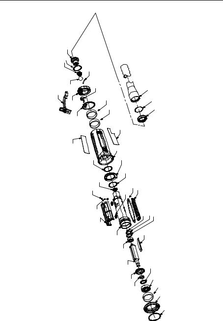
G2 Series (Horizontal) Air Grinder and Air Die Grinder Exploded Diagram - Body
1 |
|
|
|
|
|
2 |
|
|
|
|
|
3 |
|
|
|
|
|
|
7 |
|
|
|
|
4 |
6 |
|
|
|
|
9 |
|
|
|
|
|
5 |
|
|
10 |
|
|
|
|
|
11 |
|
|
|
8 |
|
|
|
|
|
|
|
12b |
|
|
12a |
|
|
12 |
|
|
|
13 |
|
14 |
|
|
|
|
|
15 |
|
|
|
19 |
17 |
21 |
23 |
22 |
|
18 |
|
|
|
|
|
|
20 |
|
|
|
|
|
|
16 |
|
|
|
|
|
25 |
|
|
|
|
|
27 |
|
|
|
|
|
|
29 |
|
|
|
|
|
30 |
|
37
38 36
24 |
26 26 |
28 |
|
31 32 33 34
35
(Dwg. 16574394)
2 |
04581229_ed3 |

G2 Series (Horizontal) Air Grinder and Air Die Grinder Parts List - Body
Item |
Part Description |
Part Number |
Item |
Part Description |
Part Number |
# |
Common parts for ALL G2H, G2X, & G2S Grinders |
|
|
|
|
1 |
Inlet Assembly |
AG2-A465 |
20 |
Flow Guide Assemblies |
|
* |
Inlet Screen |
R1602-61 |
21 |
Flow Guide O-Ring (2) |
16570798 |
2 |
Inlet Seal |
85H-167 |
|
(with each Flow Guide Assembly) |
|
|
|
||||
* |
Ball Valve Spring Seat |
AG2-592 |
* |
Flow Guide Assembly, for 250 |
AG2-A200-1 |
3 |
Ball Valve Spring |
38966 |
* |
Flow Guide Assembly, for 220 |
AG2-A200-2 |
4 |
Ball |
D10-280 |
* |
Flow Guide Assembly, for 200 |
AG2-A200-3 |
5 |
Rear Exhaust Diffuser |
AG2-123 |
* |
Flow Guide Assembly, for 180 |
AG2-A200-4 |
6 |
Lever Support |
LG2-89 |
22 |
Intake Cover Assembly |
AG2-A144 |
7 |
Throttle Lever Pin |
61H-120 |
23 |
Intake Cover O-Ring |
16570780 |
8 |
Rear Exhaust Diffuser Gasket |
AG2-223 |
24 |
Rear Rotor Bearing Retainer |
LG1-118 |
9 |
Lever Assembly |
AG2-A400 |
25 |
Rear Rotor Bearing |
R120-127 |
* |
Lever |
--- |
26 |
Rear Rotor Bearing Spacer (2) |
400-25-191 |
* |
Lock Spring |
--- |
27 |
Rotor |
AG2-53-4A |
* |
Lock Pin |
--- |
28 |
Vane Pack |
AG2-42-4 |
* |
Lever Lock |
--- |
29 |
Front End Plate |
LG2-11 |
10 |
Rear Exhaust Diffuser Muffler |
AG2-311B |
30 |
Front End Plate Spacer |
LG2-65 |
11 |
Rear Housing Muffler |
AG2-311A |
31 |
Seal Assembly |
61H-A32 |
12 |
Motor Housing Assembly |
AG2-A40 |
32 |
Front Rotor Bearing |
LG2-24 |
12a |
Warning Label |
AG2-99 |
33 |
Front Muffler |
AG2-311F1 |
12b |
Model Label |
AG2-301 |
34 |
Front Housing Cap |
AG2-202 |
14 |
Exhaust Seal |
AG2-318 |
35 |
Flange Clamp |
LG2-29 |
15 |
Front Cylinder O-Ring |
16570772 |
* |
Exhaust Hose Adapter Kit |
LG2-K284 |
16 |
Cylinder Assembly |
AG2-A3 |
36 |
Adapter |
LG2-184 |
* |
Throttle Bushing |
--- |
37 |
Hose |
3RL-284 |
17 |
Ball Valve Seat |
AG2-303S |
38 |
Retainer |
6WT-203 |
18 |
Throttle Pin Assembly |
AG2-A161 |
† |
Tune Up Kit, Includes Part Number (2, 3, |
|
19 |
Throttle Pin O-Ring |
16570806 |
|
4, 8, 10, 11, 13, 14, 15, 18, 21, 24, 25, 26, |
AG2-TK1 |
|
|
|
|
28, 31, 32, 33, & 35 ) |
|
|
|
|
† |
Muffler Kit, Includes Part Number |
AG2-MK311 |
|
|
|
|
(10, 11, & 33) |
|
|
|
|
|
|
|
|
|
|
† |
Rotor Kit, Includes Part Number |
AG2-A53-4A |
|
|
|
|
(24, 25, 26, 27, 28, 29, 30, 31 & 32) |
|
|
|
|
|
|
|
* Not illustrated.
† To keep downtime to a minimum, it is desirable to stock one of each of these service kits for every four tools in service.
04581229_ed3 |
3 |
 Loading...