


MHD56298

Form MHD56298
IMPORTANT INFORMATION:
• A copy of our “Safe Operating Practices” Manuals are always available free of charge either by downloading it from our
Technical Publications website @ www.airwinch.com or by contacting the Factory at (800) 866-5457 for North America and
(206) 624-0466 for International. The Safe Operating Practices manual must be read prior to anyone operating a
Ingersoll-Rand winch or hoist. The manual form numbers are as follows:
“Safe Operating Practices Non-Man Rider™ Winches” Manual, Form No. MHD56250
“Safe Operating Practices for Man Rider™ Winches” Manual, Form No. MHD56251
“Safe Operating Practices for Pneumatic, Hydraulic and Electric Hoists” Manual, Form No. MHD56295
• Available winch options may require additional supplements to the basic winch manual.
• For Man Rider™ winches ensure a copy of the Man Rider™ supplement is made available to the operator prior to winch
operation.
Winch Man Rider
Model: Publication No. Model: Publication No.
FA2, FA2.5,
FH2, FH2.5
FA5
FA10 MHD56252
FA2.5A MHD56236
FA2B and
HU40A
FH10MR MHD56212
Fulcrum Electric MHD56277
LS500HLP/
LS1000HLP
™ Supplements:
MHD56046
MHD56042 and
MHD56220
MHD56207
SAM0004
LS500RLP SAM0011
LS1000RLP SAM0012
LS150RLP SAM0082
LS150RLP/500/
1000
LS150RLP and
LS150PLP-PH
LS500RLP-E SAM0122
LS150RLPDP5M-F
LS150HLP SAM0222
SAM0115
SAM0120
SAM0184
• We strongly recommend that ALL maintenance on Ingersoll-Rand equipment be carried out by personnel certified by
Ingersoll-Rand, or by Ingersoll-Rand Authorized Service Centers.
• Contact the Factory if in doubt about installation, operation, inspection and maintenance instructions.
• Use only Genuine Ingersoll-Rand parts when maintaining or repairing a winch, hoist or any component of a winch or hoist.
• ANSI / ASME recommends that a winch or hoist (or any components of a winch or hoist) that has been repaired be tested
prior to being placed into service:
*Winches - ANSI / ASME B30.7 (BASE MOUNTED DRUM HOISTS) Refer to section 7.2.2 - Testing.
* Hoists - ANSI / ASME B30.16 (OVERHEAD HOISTS - UNDERHUNG) Refer to section 16.2.2 - Testing.
Form MHD56298
Edition 2
November 2004
71441844
© 2004 Ingersoll-Rand Company
Form MHD56087
S
PARTS, OPERATION AND MAINTENANCE MANUAL
THIRD GENERATION
™
AIR WINCHE
MODEL FA5A
(Dwg. MHP2415)
READ THIS MANUAL BEFORE USING THESE PRODUCTS. This manual
contains important safety, installation, operation and maintenance
information. Make this manual available to all persons responsible for the
installation, operation and maintenance of these products.
Do not use this winch for lifting, supporting, or transporting people or lifting or
supporting loads over people.
Always operate, inspect and maintain this winch in accordance with American National
Standards Institute Safety Code (ASME B30.7) and any other applicable safety codes and
regulations.
Form MHD56087
Edition 4
June 2002
71146690
© 2002 Ingersoll-Rand Company
-
-

TABLE OF CONTENTS
Description Page No.
Safety Information
Danger, Warning, Caution and Notice.................................................................................................................................................................3
Safety Summary...................................................................................................................................................................................................3
Safe Operating Instructions .................................................................................................................................................................................4
Warning Labels and Tag ......................................................................................................................................................................................4
Specifications
Model Code Explanation .....................................................................................................................................................................................5
General Specifications .........................................................................................................................................................................................6
Winch Weight and Wire Rope Capacities............................................................................................................................................................6
FA5A Performance Curve....................................................................................................................................................................................7
Description of Operation .....................................................................................................................................................................................7
Traceability ..........................................................................................................................................................................................................7
Installation
Mounting............................................................................................................................................................................................................. 8
Wire Rope........................................................................................................................................................................................................... 8
Air Supply..........................................................................................................................................................................................................10
Motor .................................................................................................................................................................................................................11
Emergency Stop and Overload System..............................................................................................................................................................11
Initial Winch Operating Checks.........................................................................................................................................................................11
Operation
Controls..............................................................................................................................................................................................................12
Winch Brakes.....................................................................................................................................................................................................15
Constant Tension Manifold (optional feature)...................................................................................................................................................15
Free Spool (optional feature) .............................................................................................................................................................................15
Inspection
Records and Reports..........................................................................................................................................................................................16
Frequent Inspection............................................................................................................................................................................................17
Periodic Inspection ............................................................................................................................................................................................17
Winches Not in Regular Use..............................................................................................................................................................................18
Inspection and Maintenance Report .................................................................................................................................................................19
Troubleshooting................................................................................................................................................................................................20
Lubrication.......................................................................................................................................................................................................21
General Lubrication...........................................................................................................................................................................................21
Wire Rope..........................................................................................................................................................................................................22
Maintenance
Maintenance Intervals........................................................................................................................................................................................23
Adjustments .......................................................................................................................................................................................................24
Disassembly.......................................................................................................................................................................................................25
Cleaning, Inspection and Repair....................................................................................................................................................................... 29
Assembly ...........................................................................................................................................................................................................29
Testing ...............................................................................................................................................................................................................34
Parts Section
Winch Cross Section Drawing .......................................................................................................................................................................... 36
Winch Drawings and Parts Lists Table of Contents...........................................................................................................................................37
Winch Parts Drawings and Parts Lists........................................................................................................................................................38 - 66
Parts Ordering Information............................................................................................................................................................................70
War rant y...........................................................................................................................................................................................................71
Office Locations ...............................................................................................................................................................................................72
2 MHD56087 - Edition 4
-
-
SAFETY INFORMATION
This manual provides important information for all personnel
involved with the safe installation, operation and proper
maintenance of this product. Even if you feel you are familiar with
this or similar equipment, you should read this manual before
operating the winch.
Danger, Warning, Caution and Notice
Throughout this manual there are steps and procedures which, if
not followed, may result in a hazard. The following signal words
are used to identify the level of potential hazard.
.
Danger is used to indicate the presence of
a hazard which will cause severe injury,
death, or substantial property damage if
the warning is ignored.
Warning is used to indicate the presence
of a hazard which can cause severe
injury, death, or substantial property
damage if the warning is ignored.
Caution is used to indicate the presence
of a hazard which will or can cause
injury or property damage if the warning
is ignored.
Notice is used to notify people of
installation, operation, or maintenance
information which is important but not
hazard-related.
Safety Summary
WARNING
• Do not use this winch for lifting, supporting, or transporting
people or lifting or supporting loads over people.
• The supporting structures and load-attaching devices used in
conjunction with this winch must provide an adequate safety
factor to handle the rated load, plus the weight of the winch
and attached equipment. This is the customer’s responsibility.
If in doubt, consult a registered structural engineer.
Ingersoll-Rand winches are manufactured in accordance with the
latest ASME B30.7 standards.
The National Safety Council, Accident Prevention Manual for
Industrial Operations, Eighth Edition and other recognized safety
sources make a common point: Employees who work near
suspended loads or assist in hooking on or arranging a load should
be instructed to keep out from under the load. From a safety
standpoint, one factor is paramount: conduct all lifting or pulling
operations in such a manner that if there were an equipment
failure, no personnel would be injured. This means keep out from
under a raised load and keep out of the line of force of any load.
The Occupational Safety and Health Act of 1970 generally places
the burden of compliance with the user, not the manufacturer.
Many OSHA requirements are not concerned or connected with
the manufactured product but are, rather, associated with the final
installation. It is the owner’s and user’s responsibility to determine
the suitability of a product for any particular use. It is
recommended that all applicable industry, trade association,
federal, state and local regulations be checked. Read all operating
instructions and warnings before operation.
Rigging: It is the responsibility of the operator to exercise caution,
use common sense and be familiar with proper rigging techniques.
Refer to ASME B30.9 for rigging information, American National
Standards Institute, 1430 Broadway, New York, NY 10018.
This manual has been produced by Ingersoll-Rand to provide
dealers, mechanics, operators and company personnel with the
information required to install, operate, maintain and repair the
products described herein.
It is extremely important that mechanics and operators be familiar
with the servicing procedures of these products, or like or similar
products, and are physically capable of conducting the procedures.
These personnel shall have a general working knowledge that
includes:
1. Proper and safe use and application of mechanics common
hand tools as well as special Ingersoll-Rand or
recommended tools.
2. Safety procedures, precautions and work habits established
by accepted industry standards.
Ingersoll-Rand cannot know of, or provide all the procedures by
which product operations or repairs may be conducted and the
hazards and/or results of each method. If operation or maintenance
procedures not specifically recommended by the manufacturer are
conducted, it must be ensured that product safety is not
endangered by the actions taken. If unsure of an operation or
maintenance procedure or step, personnel should place the product
in a safe condition and contact supervisors and/or the factory for
technical assistance.
MHD56087 - Edition 4 3
-
-
SAFE OPERATING INSTRUCTIONS
The following warnings and operating instructions have been
adapted in part from American National (Safety) Standard ASME
B30.7 and are intended to avoid unsafe operating practices which
might lead to injury or property damage.
Ingersoll-Rand recognizes that most companies who use winches
have a safety program in force at their facility. In the event that
some conflict exists between a rule set forth in this publication and
a similar rule already set by an individual company, the more
stringent of the two should take precedence.
Safe Operating Instructions are provided to make an operator
aware of dangerous practices to avoid and are not necessarily
limited to the following list. Refer to specific sections in the
manual for additional safety information.
1. Only allow people, trained in safety and operation of this
product, to operate and maintain this winch.
2. Only operate a winch if you are physically fit to do so.
3. When a “DO NOT OPERATE” sign is placed on the winch,
or controls, do not operate the winch until the sign has been
removed by designated personnel.
4. Before each shift, inspect winch for wear and damage. Never
use a winch that inspection indicates is worn or damaged.
WARNING LABELS AND TAG
5. Never lift a load greater than the rated capacity of the winch.
Refer to “SPECIFICATIONS” section.
6. Keep hands, clothing, etc., clear of moving parts.
7. Never place your hand in the throat area of a hook or near
wire rope spooling onto or off of the winch drum.
8. Always rig loads properly and carefully.
9. Be certain the load is properly seated in the saddle of the
hook. Do not support the load on the tip of the hook.
10. Do not “side pull” or “yard”.
11. Always ensure that you, and all other people, are clear of the
path of the load. Do not lift a load over people.
12. Never use the winch for lifting or lowering people, and never
allow anyone to stand on a suspended load.
13. Ease the slack out of the wire rope when starting a lift or pull.
Do not jerk the load.
14. Do not swing a suspended load.
15. Do not leave a suspended load unattended.
16. Never operate a winch with twisted, kinked or damaged wire
rope.
17. Pay attention to the load at all times when operating the
winch.
18. Never use the wire rope as a sling.
19. After use, or when in a non-operational mode, the winch
should be secured against unauthorized and unwarranted use.
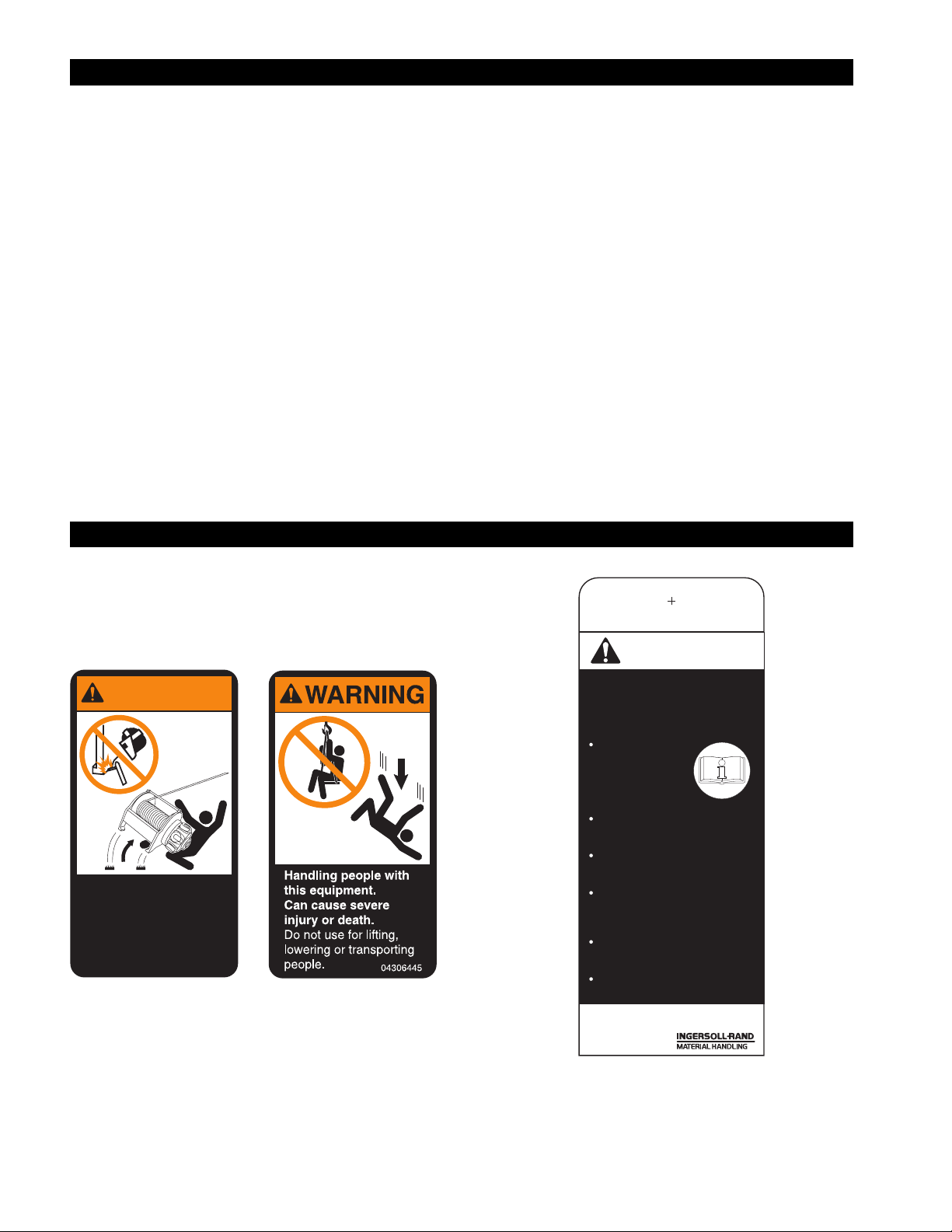
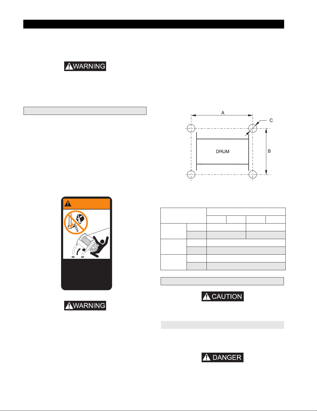
Each winch is shipped from the factory with the warning labels
and tag shown. If the labels or tag are not attached to your winch,
order new labels and tag and install. Refer to the parts list for the
part numbers. Labels and tag shown are smaller than actual size.
WARNING
Welded mountings
can fail.
Can cause severe
injury or death.
Do not weld, braze or
solder to winch.
71270813
WARNING
Failure to follow these
warnings may result in
death, severe injury or
property damage:
Do not operate
this winch before
reading operation
and maintenance
manual.
Do not lift people or loads
over people.
Do not lift more than rated
load.
Do not allow less than three
wraps of wire rope to remain
on drum at all times.
Do not operate a damaged
or malfunctioning winch.
Do not remove or obscure
warning labels.
Read the latest edition of ASME B30.7.
Comply with other federal, state and local rules.
P/N 71056410/A
for winches
?
4 MHD56087 - Edition 4
-
-

SPECIFICATIONS
Model Code Explanation: (Example FA5A-LXK1G) FA 5 A - L X K 1 G
Series
FA = Force 5 Air Powered
Capacity: (Based on wire rope at mid drum)
5 = (5 tons (10,000 lbs [4,536 kg])
Generation:
A = Third Generation
Drum Length:
S = Short without Drum Brake (15 inches [381 mm])
S = Short with Drum Brake (12 inches [305 mm])
L = Long without Drum Brake (27 inches [686 mm])
L = Long with Drum Brake (24 inches [610 mm])
Drum Brake: Note: addition of drum brake reduces the drum length 3 inches [76 mm]
A = Automatic Drum Brake
M = Manual Drum Brake
X = None
Disc Brake:
K = Automatic Disc Brake (Standard)
X=None
Control:
1 = Winch mounted lever throttle (Standard)
* 2 = Remote pilot pendant throttle with standard length (6 ft/1.8 m) hose
** 2XX = Remote full flow lever throttle (maximum 20 ft/6 m)
** 3XX = Remote pilot pendant throttle (standard = 6 ft/1.8 m; maximum 66 ft/20 m)
** 4XX = Remote pilot lever throttle (maximum 66 ft/20 m)
5XX = Remote electric over air throttle †
Options:
7 = Drum grooving (Number = wire rope size in sixteenths, e.g. 7/16 inch) †
C = Low Temperature Components; specify -10° C (14° F) or -20° C (-4° F)
D = Drum divider flange and additional wire rope anchor †
E = Construction Cage
F = Free spool clutch (available only with manual drum brake)
G = Drum Guard
H = Open Front frame for horizontal pulling
K = K6 footprint base
*** M1 = Material Traceability (typical material results) ††
*** M2 = Material Traceability (actual material results) ††
*** M3 = Material Traceability (actual material results for these parts in finished, as-delivered condition) ††
N = Type Approval - Specify: • American Bureau of Shipping (ABS)
• Det Norske Veritas (DNV) • Lloyd’s Register of Shipping (LRS)
Q = Special Paint
T = Tensioning Manifold
U = Underwound wire rope operation (available only with automatic disc brake)
V = Press Roller †
-E = Compliance with European Community Machinery Directive: • Muffler • Overload Device
• Main air supply emergency shut off • Drum Guard • CE Documentation
Notes: *
MHD56087 - Edition 4 5
Available only with auto disc brake or with auto drum brake.
Remote throttles are provided with 6 feet (1.8 metres) of hose. Specify hose lengths greater than 6 feet (1.8 metres).
**
Contact your Ingersoll-Rand distributor or the factory for control acceptability for hose lengths greater than 60 feet
(18.3 metres). Metric lengths are provided for reference only, order lengths in feet.
Documentation, witness testing and material traceability available; must be requested at time of order. Specify options or
***
contact the factory or your nearest Ingersoll-Rand distributor for information.
Not covered in this manual.
†
Refer to ‘Traceability’ on page 7 for a description of the differences between M1, M2 and M3.
††
-
-

General Specifications
Air System
Rated Performance
(at rated pressure / volume)
Air Motor Pipe Inlet Size 1.25 inches
Minimum Air System Hose Size 1.5 inches
Maximum Stall at First Layer 17,000 lbs
Drum Barrel Diameter 12.75 inches
Drum Flange Diameter 24.25 inches
Winch Net Weight (without wire rope)
Model lbs
FA5A-SXK1 1,048
FA5A-SMK1 1,170
FA5A-SAK1 1,175
FA5A-SMX1 1,120
FA5A-SAX1 1,165
FA5A-LXK1 1,251
FA5A-LMK1 1,363
FA5A-LAK1 1,390
FA5A-LMX1 1,333
FA5A-LAX1 1,378
Rated Operating Pressure 90 psig (6.3 bar/630 kPa)
Air Consumption
(at rated pressure and load)
Mid Drum Line Pull 10,000 lbs
Mid Drum Line Speed 32 fpm
kg Model lbs kg
476 FA5A-SXK2 1,050 477
532 FA5A-SMK2 1,145 520
534 FA5A-SAK2 1,175 534
509 N/A - - - - - 530 FA5A-SAX2 1,165 530
569 FA5A-LXK2 1,263 574
620 FA5A-LMK2 1,380 627
632 FA5A-LAK2 1,390 632
606 N/A - - - - - 626 FA5A-LAX2 1,378 626
700 scfm
20 cu.m/min
4,536 kg
10 m/min
32 mm
38 mm
7,727 kg
324 mm
616 mm
Winch Wire Rope Storage Capacities (feet/metres)
Drum Length
inches
12
15
24
27
* Per ASME B30.7 wire rope top layer must be located a minimum of 1/2 inch (13 mm) below drum flange. The wire rope storage capacities
listed may vary from figures stated elsewhere.
mm feet metres feet metres
305
381 844 256 619 197
610 1,373 416 1,010 321
686 1,549 469 1,140 362
Storage Notes
Full Drum Storage less
1/2 inch (13 mm) (meets
ANSI B30.7) *
5/8 inch
668 202 489 156
Wire Rope Diameter
16 mm 3/4 inch 18 mm
6 MHD56087 - Edition 4
-
-
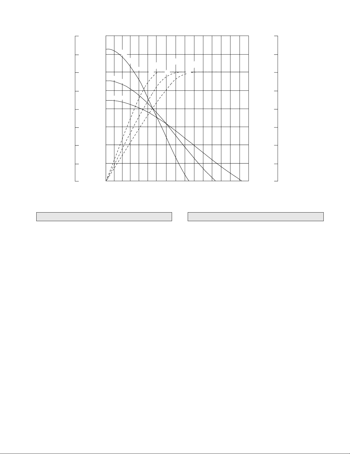
FA5A Performance Curve
7257
6350
5443
4536
3629
Line Pull (kgs)
2122
1814
907
(Dwg. MHP0895)
16000
1st Wrap Line Pull
14000
12000
10000
Line Pull (lbs x 100)
0
8000
6000
4000
2000
0
Half Drum
Full Drum
0
16
32
48
80
64
Half Drum
1st Wrap
96
112
Line Speed (ft/min)
128
144
Full Drum
160
176
192
208
224
900
800
700
600
500
400
300
200
100
240 256
25.5
22.7
19.8
16.9
3
14.2
11.3
Air Consumption (scfm)
Air Consumption (m /min)
8.5
5.7
2.8
Description of Operation
FA 5A winches are air powered, planetary geared units designed
for lifting and pulling applications. FA5 A winches are supplied
with either an internal automatic disc brake, a manual or automatic
externally mounted drum band brake, or a combination of both.
The output from an externally mounted piston air motor is
transmitted through a coupling and shaft to the planetary reduction
gear assembly.
The output from the planetary reduction gear assembly is
connected to the wire rope drum through the output shaft.
The disc brake attaches to the outboard upright opposite the motor
end and is connected to the intermediate sun gear through the
brake shaft. The disc brake is automatically applied when the
winch is in the neutral or operated in the haul-in positions;
disengaged when the winch is operated in the payout direction.
During winch operation a sprag type clutch in the disc brake
allows drum rotation in the haul-in direction with the disc brake
engaged. This ensures the brake will respond quickly to hold the
load when winch operation stops. Operation of the winch in the
payout direction directs pressurized air to the disc brake
diaphragm to overcome spring tension and release the brake.
When the payout operation is complete the air is vented and the
brake is automatically applied.
The drum band brake operates by applying a friction force
between the drum band and the winch drum. The manual brake
requires an operator to engage and disengage the brake using a
lever located near the air motor end of the winch. The automatic
drum band brake operation is similar to the disc brake with the
following exception: the automatic drum band brake fully
disengages in both the haul-in and payout directions.
Traceability
Load bearing parts are documented to provide traceability.
Documentation includes chemical and physical properties of raw
material, heat treating, and hardening, tensile and charpy tests as
required for the part.
Units with M1, M2 or M3 in the model code have traceable loadbearing components.
M1–Material Traceability certificates according to EN 10204 (Ex
DIN 50049) 2.2 on load bearing parts. Conformity documents
affirm (by the manufacturer) that parts are in compliance with the
requirements of the order based on non-specific inspection and
testing (i.e. results are typical material properties for these parts).
M2–Material Traceability certificates according to EN 10204 (Ex
DIN 50049) 3.1b on load bearing parts. Conformity documents
affirm (by a department independent of the manufacturing
department) that the actual parts are in compliance with the
requirements of the order based on specific inspection and testing
(i.e. results are actual material properties for these parts).
M3–Material Traceability certificates according to EN 10204 (Ex
DIN 50049) 3.1b on load bearing parts. Conformity documents
affirm (by a department independent of the manufacturing
department) that the actual parts used in the product are in
compliance with the order based on specific inspection and testing
(i.e. results are actual material properties for these parts in a
finished, as delivered condition).
Components with part numbers ending in CH are charpy parts for
use under extreme cold conditions. Traceability requirements must
be stated when reordering these parts for continued certification.
MHD56087 - Edition 4 7
-
-
INSTALLATION
Prior to installing the winch, carefully inspect it for possible
shipping damage. Winches are supplied fully lubricated from the
factory. Check oil levels and adjust as necessary before operating
winch. Refer to “LUBRICATION” section for recommended oils.
• Owners and users are advised to examine specific, local or
other regulations, including American National Standards
Institute and/or OSHA Regulations which may apply to a
particular type of use of this product before installing or
putting winch to use.
Mounting
Refer to Dwg. MHP0124 and Table 1 on page 8.
Care must be taken when moving, positioning or mounting the
winch. Ensure that the winch, when lifted, will be properly
balanced. Determine the weight of the winch by referring to the
“SPECIFICATIONS” section. Lift the winch 3 to 4 inches (75 to
100 mm) off the ground. Verify winch is balanced and secure
before continuing lift. Mount the winch so the axis of the drum is
horizontal and that the motor vent cap is not more than 15° off top
vertical center. If the winch is to be mounted in an inverted
position, the motor case must be rotated to position the vent cap at
the top and adequate clearance must be provided for control valve
operation. The breather (8) and drain plug (21) on the disc brake
must be swapped.
3. Mounting bolts must be 3/4 inch-NC (18 mm) Grade 8 or
better. Use self-locking nuts or nuts with lockwashers.
4. Tighten 3/4 inch (18 mm) mounting bolts evenly and torque
to 380 ft lbs. (515 Nm) for dry thread fasteners. If the
fasteners are plated, lubricated or a thread locking compound
is used, torque to 280 ft lbs. (380 Nm).
5. Maintain a fleet angle between the lead sheave and winch of
no more than 1-1/2°. The lead sheave must be on a center line
with the drum, and for every inch (25 mm) of drum length, be
at least 1.6 feet (0.5 metre) from the drum. Refer to Dwg.
MHP0498 on page 10.
6. Do not weld to any part of the winch.
(Dwg. MHP0124)
WARNING
Welded mountings
can fail.
Can cause severe
injury or death.
Do not weld, braze or
solder to winch.
• .Winch frame material is not suitable for welding. FA5A
winches must only be mounted by bolting to a suitable
foundation. Do not attempt to mount winch by welding to a
foundation structure. Refer to warning label part number
71270813 on winch.
1. Winch mounting surface must be flat and of sufficient
strength to handle the rated load plus the weight of the winch
and attached equipment. An inadequate foundation may
cause distortion or twisting of winch uprights and side rails
resulting in winch damage.
2. Make sure the mounting surface is flat to within 1/32 inch
(0.8 mm). Shim if necessary.
71270813
Table 1 - Mounting Bolt Hole Dimensions
Dimension
“A”
“B”
“C”
in. 17.89 29.89
mm 455 760
in. 22
mm 559
in. 0.81
mm 21
Drum Length (inches)
12 15 24 27
Wire Rope
• Maintain at least 3 tight wraps of wire rope on drum at all
times. Refer to Dwg. MHP0498 on page 10.
Standard and Open Frame (Face) Winch
Install the winch such that the wire rope, when at the take-off
angle limits does not contact the mounting surface. Refer to Dwg.
MHP1142 on page 9.
•
• Exceeding wire rope take-off angles will cause wire rope to
come into contact with winch frame supports resulting in
damage to wire rope and winch.
8 MHD56087 - Edition 4
-
-
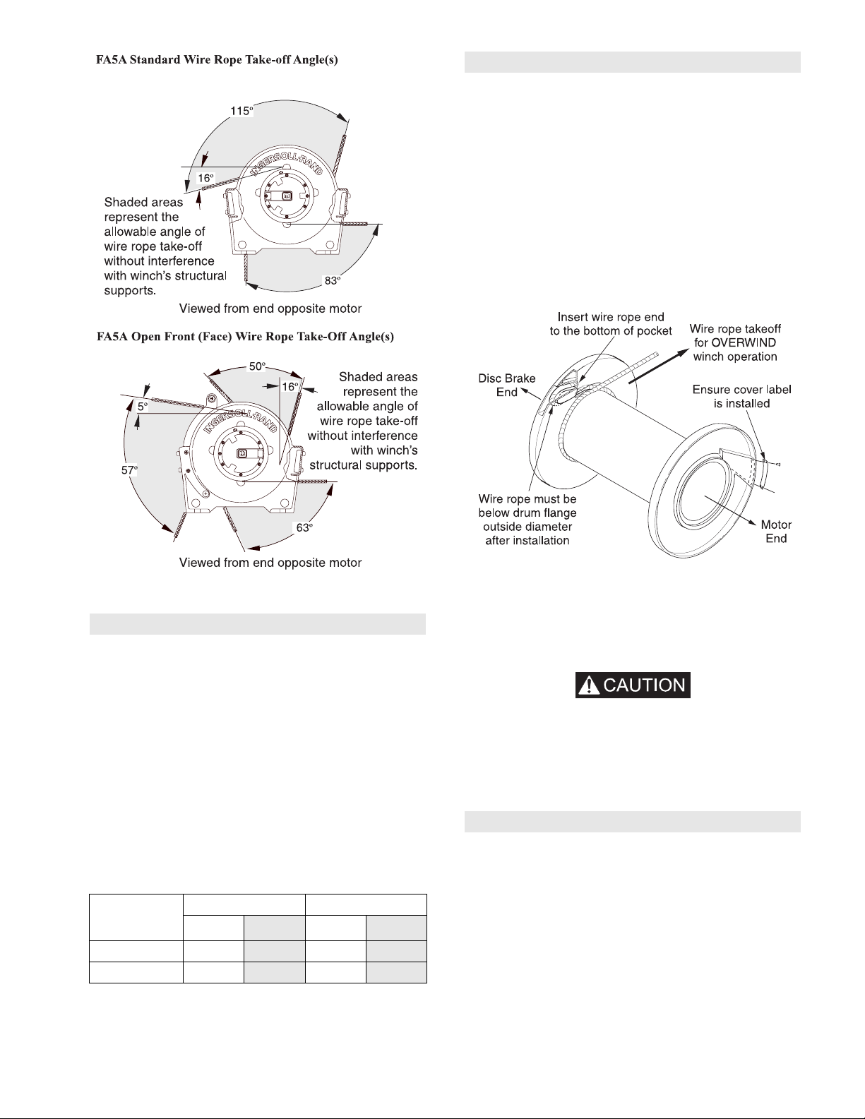
Installing Wire Rope
Refer to Dwg. MHP0652 on page 9.
1. Cut wire rope to length and fuse end to prevent fraying of
strands in accordance with the wire rope manufacturer’s
instructions.
2. Feed the end of the wire rope into the wire rope anchor hole
in the drum and pull through approximately three feet
(1 metre) of wire rope.
3. Forming a large loop with the wire rope, insert the end back
into the top of the anchor hole.
4. Place the wire rope wedge into the wire rope anchor pocket in
the drum. Install the wedge such that the wire rope will wrap
around the wedge as shown in Dwg. MHP0652 on page 9.
Wire Rope Installation
(Dwg. MHP1142)
Wire Rope Selection
Consult a reputable wire rope manufacturer or distributor for
assistance in selecting the appropriate type and size of wire rope,
and where necessary, a protective coating. Use a wire rope which
provides an adequate safety factor to handle the actual working
load and that meets all applicable industry, trade association,
federal, state and local regulations.
When considering wire rope requirements the actual working load
must include not only the static or dead load but also loads
resulting from acceleration, retardation and shock load.
Consideration must also be given to the size of the winch wire
rope drum, sheaves and method of reeving. Wire rope construction
must be 6 X 19 or 6 X 37 Extra Improved IWRC right lay. Refer to
Table 2 for minimum and maximum recommended wire rope
diameters.
Table 2 - Minimum and Maximum Wire Rope Size
Wire Rope
Anchor Part
No.
Contact Factory 1/4
24258 9/16
Note: To maintain 5:1 safety factor ratio 9/16 inch (14 mm) wire
rope must be used.
Minimum Maximum
inch
mm inch mm
81/213
14 3/4 18
(Dwg. MHP0652)
5. Pull the wire rope into position in the drum anchor pocket.
Ensure the wire rope is installed below the edge of the drum
flange diameter. Use of a copper drift or similar tool may be
required to fully insert wire rope and wedge into the anchor
pocket.
CAUTION
• Make sure first wrap of wire rope is tight and lays flush
against drum flange.
• Ensure correct wire rope anchor is used.
• Install wire rope to come off drum in an overwind position.
Improper installation of wire rope can result in failure of the
disc brake to hold load. Refer to Dwg. MHP0652 on page 9.
Safe Wire Rope Handling Procedures
1. Always use gloves when handling wire rope.
2. Never use wire rope which is frayed or kinked.
3. Never use wire rope as a sling.
4. Always ensure wire rope is correctly spooled and the first
layer is tight against the drum.
5. Always follow wire rope manufacturers’ recommendation on
use and maintenance of wire rope.
MHD56087 - Edition 4 9
-
-
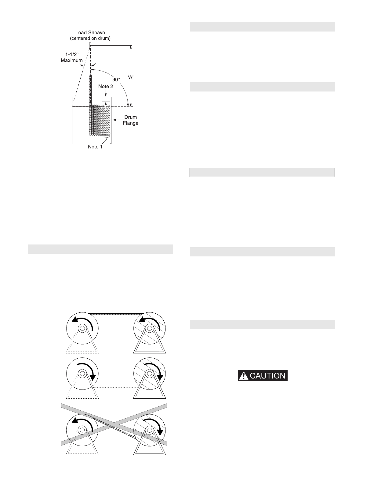
Wire Rope and Drum Diagram
(Dwg. MHP0498)
‘A’ = 1.6 feet (0.5 metre) per inch of drum length:
‘A’ = 19.2 feet (5.85 metres) for 12 inch drum.
‘A’ = 24.0 feet (7.31 metres) for 15 inch drum.
‘A’ = 38.4 feet (11.7 metres) for 24 inch drum.
‘A’ = 43.2 feet (13.2 metres) for 27 inch drum.
Notes:
1. Maintain a minimum of 3 tight wraps of wire rope on drum at
all times.
2. Ensure wire rope does not exceed top layer requirement.
Refer to “SPECIFICATIONS” section.
3. If drum is grooved ensure wire rope width is proper size to
seat in grooves on last wrap.
Rigging
Make sure all wire rope blocks, tackle and fasteners have a
sufficient safety margin to handle the required load under all
conditions. Do not allow wire rope to contact sharp edges or make
sharp bends which will cause damage to wire rope, use a sheave.
Refer to the wire rope manufacturer’s handbook for proper sizing,
use and care of wire rope.
Safe Installation Procedures
1. Do not use wire rope as a ground (earth) for welding.
2. Do not attach a welding electrode to winch or wire rope.
3. Never run the wire rope over a sharp edge. Use a correctly
sized sheave.
4. When a lead sheave is used, it must be aligned with the center
of the drum. The diameter of the lead sheave must be at least
18 times the diameter of the wire rope. Refer to Dwg.
MHP0498 on page 10.
5. Always maintain at least three full, tight wraps of wire rope
on the drum.
Air Supply
The air supply must be clean, free from moisture and lubricated to
ensure optimum motor performance. Foreign particles, moisture
and lack of lubrication are the primary causes of premature motor
wear and breakdown. Using an air filter, lubricator and moisture
separator will improve overall winch performance and reduce
unscheduled down time. The air consumption is 700 scfm
(20 cu. m/min) at rated operating pressure of 90 psig (6.3 bar/
630 kPa) at the winch motor inlet. If air supply varies from
recommended, then winch performance will change.
Wire Rope Spooling
To compensate for uneven spooling and the decrease in line pull
capacity as the drum fills up, use as short a wire rope as practical.
When rewinding apply tension to the end of the wire rope to
eliminate line slack. This helps achieve level winding and tight
spooling.
Support wire rope spool and have wire rope come off top of spool
and over top of winch drum. This will prevent damage to wire rope.
Overwound
CORRECT
Winch
Drum
CORRECT
Winch
Drum
INCORRECT
Wire Rope
Spooling
Underwound
Wire Rope
Spooling
Spool
Spool
Air Lines
The inside diameter of the winch air supply lines must be at least
1-1/2 inch (38 mm). Before making final connections, all air
supply lines should be purged with clean, moisture free air or
nitrogen before connecting to winch inlet. Supply lines should be
as short and straight as installation conditions will permit. Long
air transmission lines and excessive use of fittings, elbows, tees,
globe valves etc. cause a reduction in pressure due to restrictions
and surface friction in the lines.
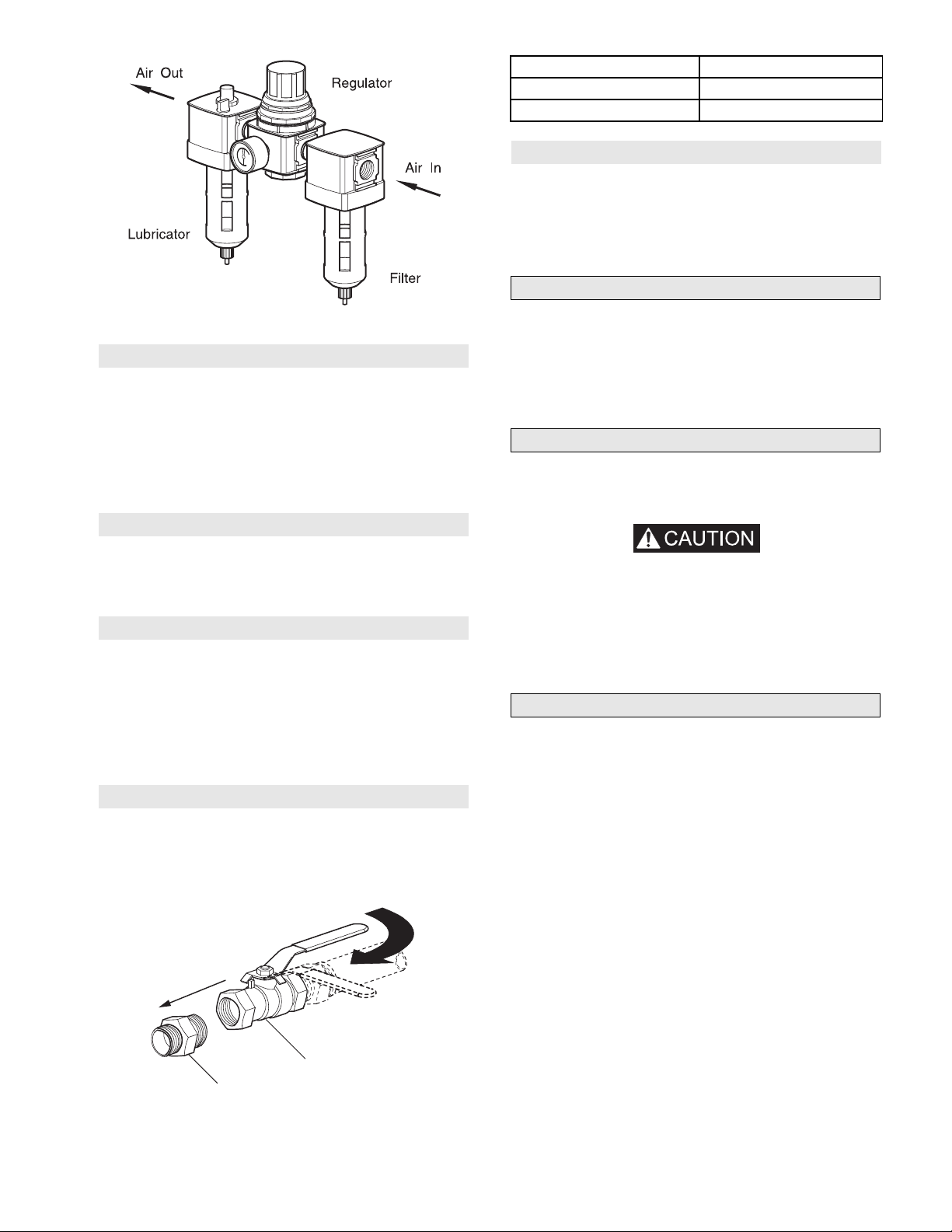
Air Line Lubricator
Refer to Dwg. MHP0191 on page 11.
Always use an air line lubricator with these motors. The lubricator
must have an inlet and outlet at least as large as the inlet on the
motor directional control valve. Install the air line lubricator as
close to the air inlet on the motor as possible.
• Lubricator must be located no more than 10 ft. (3 m) from
the motor.
• Shut off air supply before filling air line lubricator.
The air line lubricator should be replenished daily and set to
provide 6 to 9 drops per minute of ISO VG 32 (SAE 10W) oil. A
fine mist will be exhausted from throttle control valve when air
line lubricator is functioning properly.
Winch
Drum
(Dwg. MHP2450)
10 MHD56087 - Edition 4
Wire Rope
Spooling
Spool
-
-
Description of Part Part Number
Fitting, Nipple 51704
Ball Valve 71404628
Mufflers (optional feature)
Make sure mufflers are installed in winch exhaust manifold and
control valve exhaust ports. An additional muffler is used on
winches equipped with an emergency stop and overload device.
Check mufflers periodically to ensure they are functioning
correctly.
Motor
(Dwg. MHP0191)
Air Line Filter
Refer to Dwg. MHP0191 on page 11.
It is recommended that an airline strainer/filter be installed as
close as practical to the motor air inlet port, but before lubricator,
to prevent dirt from entering the valve and motor. The
strainer/filter should provide 20 micron filtration and include a
moisture trap. Clean the strainer/filter periodically to maintain its
operating efficiency.
Air Pressure Regulator
Refer to Dwg. MHP0191 on page 11.
If an air pressure regulator is used, install between the lubricator
and filter.
Moisture in Air Lines
Moisture that reaches the air motor through air supply lines is a
primary factor in determining the length of time between service
overhauls. Moisture traps can help to eliminate moisture. Other
methods, such as an air receiver which collects moisture before it
reaches the motor, or an aftercooler at the compressor that cools
the air to condense and collect moisture prior to distribution
through the supply lines are also helpful.
Ball Valve Shut Off
Refer to Dwg. MHP2459 on page 11.
Install in air supply line upstream of control valve. Ensure ball
valve is conveniently located and easily accessible. Advise
operators and support personnel of its location and use.
Open
Air
Flow
Closed
For optimum performance and maximum durability of parts,
provide an air supply of 700 scfm (20 cu. m/m) at 90 psig (6.3
bar/630 kPa). The air motor should be installed as near as possible
to the compressor or air receiver. Recommended pressures and
volumes are measured at point of entry to air motor directional
control valve.
Emergency Stop and Overload System
Refer to Dwg. MHP2434 on page 50.
Air supply line is connected to air control valve. When emergency
stop or overload valve is activated, all winch movement will stop.
• If winch continues to move (payout load) after emergency
stop activates, brake(s) are not holding load and may require
adjustment or repair.
When control valve senses a preset pressure difference between
ports, a pilot signal is sent to stop flow of air, all winch movement
will stop.
Initial Winch Operating Checks
Winches are tested for proper operation prior to leaving the
factory. Before the winch is placed into service the following
initial operating checks should be performed.
1. When first running the motor inject some light oil into the
inlet connection to provide initial lubrication.
2. When first operating the winch it is recommended that the
motor be driven slowly in both directions for a few minutes.
For winches that have been in storage the following start-up
procedures are required.
1. Give the winch an inspection conforming to the requirements
of “Winches Not in Regular Use” in the “INSPECTION”
section.
2. Pour a small amount of ISO VG 32 (10W) lubricant in the
motor inlet port.
3. Operate the motor for 10 seconds in both directions to flush
out any impurities.
4. Check to ensure oil levels are “full”.
5. The winch is now ready for normal use.
Ball Valve
Fitting,
Nipple
(Dwg. MHP2459)
MHD56087 - Edition 4 11
-
-
OPERATION
The four most important aspects of winch operation are:
1. Follow all safety instructions when operating the winch.
2. Allow only people trained in safety and operation of this
winch to operate this equipment.
3. Subject each winch to a regular inspection and maintenance
procedure.
4. Be aware of winch capacity and weight of load at all times.
CAUTION
• To avoid damage to rigging, the structure supporting the
rigging and winch, do not “two-block*” the end of wire rope.
* Two blocking occurs when the winch wire rope is multi reeved
using two separate sheave blocks which are allowed to come into
contact with each other during winch operation. When this occurs
extreme forces are exerted on the wire rope and sheave blocks
which may result in equipment and or rigging failure.
WARNING
• The winch is not designed or suitable for lifting, lowering or
moving people. Never lift loads over people.
Operators must be physically competent. Operators must have no
health condition which might affect their ability to act, and they
must have good hearing, vision and depth perception. The winch
operator must be carefully instructed in his duties and must
understand the operation of the winch, including a study of the
manufacturer’s literature. The operator must thoroughly
understand proper methods of hitching loads and should have a
good attitude regarding safety. It is the operator’s responsibility to
refuse to operate the winch under unsafe conditions.
Controls
A spring loaded, motor mounted, live air manual throttle control
valve is supplied as a standard feature on this winch. Optional
remote throttle controls are available. Reference model code on
the winch nameplate and compare it to the “SPECIFICATIONS”
section on page 5 to determine your configuration. The throttle
control provides operator control of the motor speed and direction
of drum rotation. Operate winch throttle control using smooth,
even movements. Do not slam or jerk throttle controls during
operation.
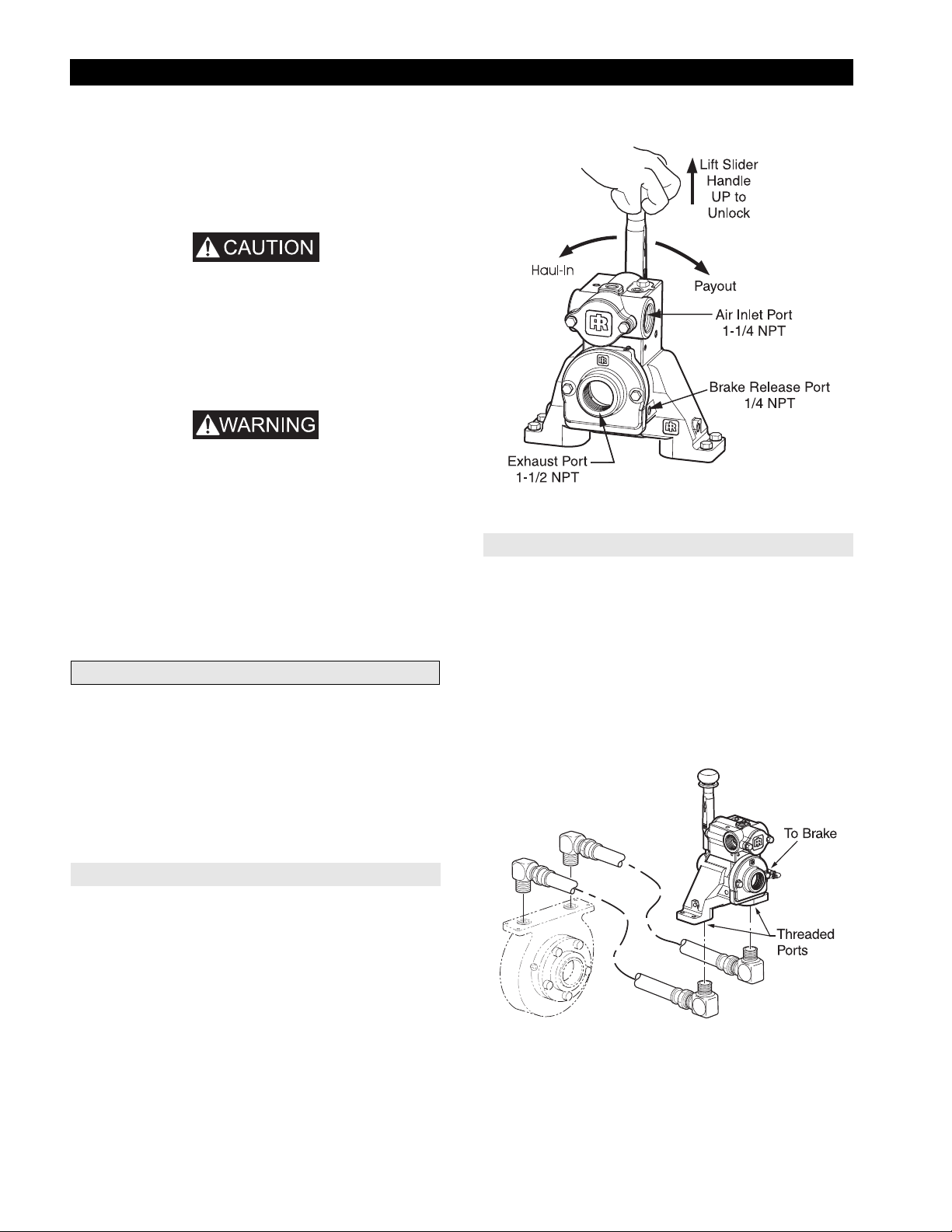
Winch Mounted Throttle Control Valve Operation
(Dwg. MHP1809)
Remote Mounted Control Valve (optional feature)
Refer to Dwg. MHP2043 on page 12.
Provides for remote mounting of winch control at a fixed location
at up to 20 feet (6 metres) away from winch motor. Air hoses
connect throttle to winch motor to provide winch operation.
Move control throttle handle to the right (clockwise) to payout
wire rope and to the left (counterclockwise) to haul-in wire rope.
Avoid sudden movements of control valve to ensure smooth
operation of winch.
Remote Mounted Control Valve
Winch Mounted Control Valve (standard feature)
Refer to Dwg. MHP1809 on page 12.
The spring loaded, live air, manual control valve mounts to rotary
housing.
To operate control valve, place palm of hand on control knob and
wrap fingers around flange of sliding handle. Squeeze fingers,
lifting sliding handle up to unlock control lever. Shift control lever
in desired direction to payout or haul-in wire rope.
As viewed from air motor end, move control throttle handle to the
right (clockwise) to payout wire rope and to the left
(counterclockwise) to haul-in wire rope. Avoid sudden movements
of control valve to ensure smooth operation of winch.
When released, handle will return to neutral or center position.
The sliding handle will drop down to engage and lock control
handle in place.
12 MHD56087 - Edition 4
(Dwg. MHP2043)
-
-

Remote Pilot Pendant Control (optional feature)
Underwound Operation (optional feature)
Refer to Dwg. MHP2233 on page 13.
Provides for remote winch control at distances of up to 50* feet
(15 metres) away from winch. The pendant pilot control throttle is
a two lever movable control station for winch operation. Pilot
pressure from pendant pilot control throttle activates winch control
valve. The winch control valve, located on winch motor, controls
motor speed and direction of drum rotation. Direction of rotation
is determined by the pendant lever pressed.
Pendant Hose and Operating Levers
Red
Green
Payout
Load
Yellow
Haul-In
Load
Underwound operation is where wire rope haul-in or payout is off
the bottom of drum. This is a special operation and requires a
winch specifically designed for this usage.
Underwound operation requires a reverse bias valve installed in
the control valve.
Control valve operation will be opposite as shown in Dwg.
MHP1809 on page 12. As viewed from air motor end, lift slider
handle up to unlock control lever. Move control throttle handle to
the left (counterclockwise) to payout, and to the right (clockwise)
to haul-in.
Emergency Stop (optional feature)
Refer to Dwg. MHP2047 on page 13.
Emergency stop device is located on the control valve. When
activated, winch drum rotation will immediately cease. To activate
emergency stop, conduct the following:
1. Press (push down) red palm valve, located on top of control
valve.
Emergency Stop Operation
(Dwg. MHP2233)
Press pendant levers using smooth, even movements. To operate
winch using pendant:
1. To haul-in, press ‘RIGHT’ lever.
2. To payout, press ‘LEFT’ lever.
3. To throttle operating speed, regulate amount pendant lever is
pressed. Press lever fully for maximum speed; partially for
slower speeds.
4. To stop haul-in or payout operation, release pendant lever.
Lever will spring return to off position and winch operation
will stop.
Remote Pilot Lever Throttle (optional feature)
Refer to Dwg. MHP2444, item 358 on page 58.
Provides for remote winch control at distances of up to 50* feet
(15 metres) away from winch. The lever pilot control throttle is a
fixed mount lever control station for winch operation. Pilot
pressure from lever pilot control throttle activates winch control
valve. The winch control valve, located on winch motor, controls
motor speed and direction of drum rotation. Direction of rotation
is determined by direction in which lever is shifted.
* For distances greater than 50 feet (15 metres) contact
Ingersoll-Rand Technical Support for control suitability.
(Dwg. MHP2047)
• If winch overload occurs, overload device, if equipped, also
stops winch. To operate winch after an overload, reduce load
and reset overload.
Emergency Stop Reset
Refer to Dwg. MHP2048 on page 14.
1. Rotate red stop button, in counterclockwise direction until
red stop button ‘pops’ up.
2. Winch is ready to resume operation.
MHD56087 - Edition 4 13
-
-

Emergency Stop Reset
Overload Valve Adjustment
(Dwg. MHP2048)
Overload Device (optional feature)
An overload device is available on winches with the emergency
shutoff option. Overload device operation is based on differential
pressure between air motor inlet and exhaust. The overload device
is factory preset to actuate at 150% (± 25%) of winch rated
capacity. When an overload condition is sensed, the valve poppet
closes, to cut off supply air to winch, stopping winch operation. If
an overload shutoff occurs, winch load must be reduced. Reset the
overload valve and operate winch in payout direction to lower
load. Refer to ‘Emergency Stop Reset’ section on page 13.
Overload Valve Adjustment
Refer to Dwg. MHP2216 on page 14.
5/16 in. or 8 mm open ended wrench required.
1. Adjust overload valve by turning adjustment screw located at
bottom of control valve.
2. Rotating adjustment screw clockwise will increase pressure
required to activate overload valve.
• This adjustment can cause overload device to NOT activate
before winch’s overload limit is exceeded. This procedure
should only be done by personnel trained in testing and
servicing this winch.
(Dwg. MHP2216)
Checking Overload Valve Setting
1. Attach load line to a load that is calibrated to maximum load
for which winch is rated.
2. Move control lever to haul-in position. If winch does not lift
load, adjust the adjustment screw. Refer to ‘Overload Valve
Adjustment’ section on page 14.
Setting the Overload
Attach load line to a load that is calibrated to 150% of winch rated
capacity. Shift control lever to haul-in position.
1. If overload valve activates, reset overload valve. Winch is
ready for normal operation.
2. If winch lifts load, lower load. Turn adjustment screw
counterclockwise in 1/4 turn increments until overload valve
activates when control lever is shifted to haul-in position.
After each 1/4 turn, retest winch.
Overload Valve Reset
3. Rotating adjustment screw counterclockwise will decrease
pressure required to activate overload valve.
(Dwg. MHP2049)
14 MHD56087 - Edition 4
-
-
Winch Brakes
Automatic Drum Brake (optional feature)
Automatic Disc Brake
The automatic disc brake is spring applied, air released. When the
winch is operated in payout direction, air pressure acting on the
diaphragm overcomes spring pressure and releases brake. The
brake automatically engages when winch operation is returned
from payout direction to neutral or when shifted to haul-in
direction. When winch is in neutral or haul-in positions the brake
air is vented and brake springs apply the brake. The springs, acting
on the pressure plate, compress brake friction and separator plates
and engage brake to prevent drum rotation in payout direction.
The cam type sprag clutch assembly allows drum rotation in haulin direction with brake plates engaged, but prevents drum from
rotating in payout direction.
A minimum air pressure of 25 psi (1.72 bar/172.4 kPa) is required
to release brake.
Disc brake adjustment is not required. If disc brake does not
operate properly it must be disassembled, inspected and repaired.
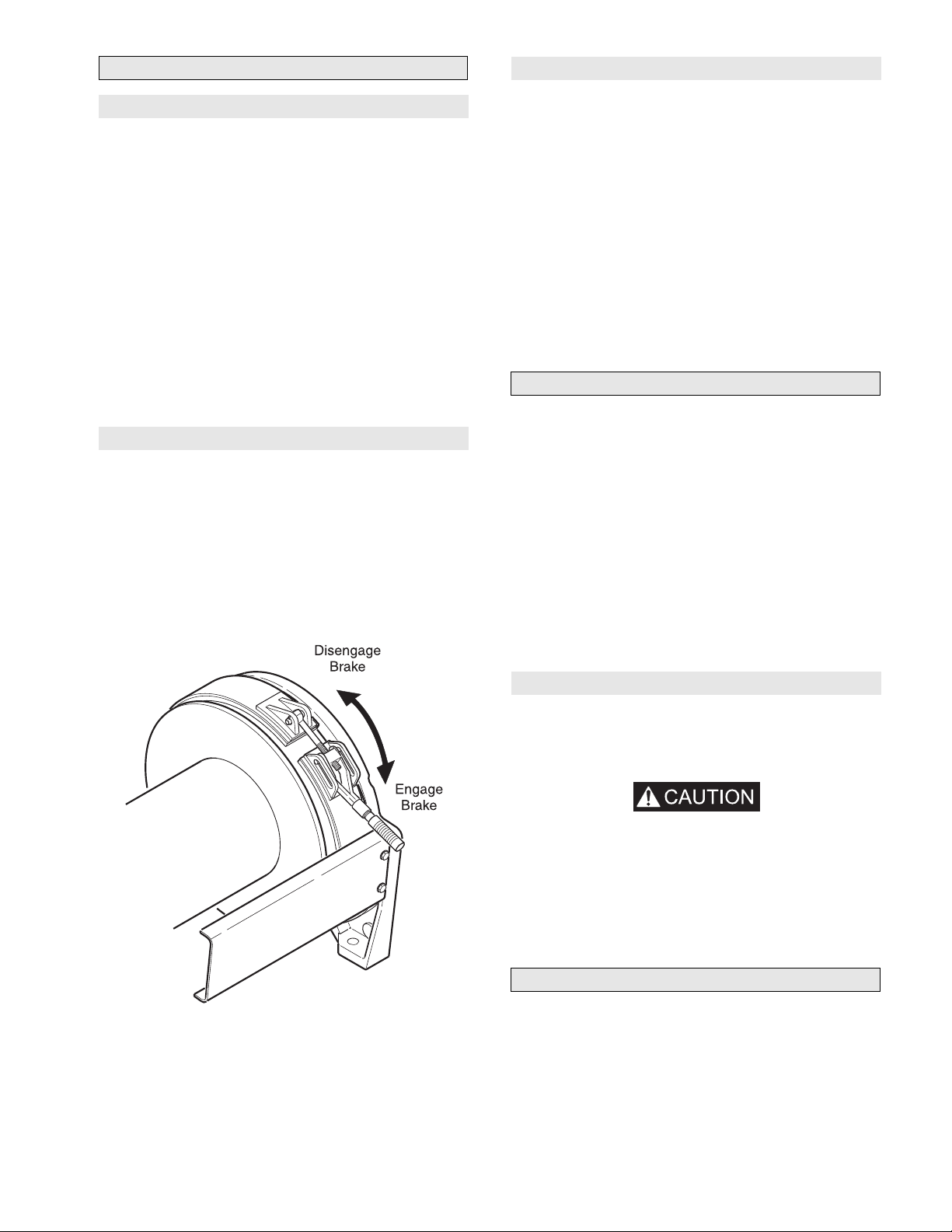
Manual Drum Brake (optional feature)
Refer to Dwg. MHP1375 on page 15.
The manual drum brake may be applied by pushing down on the
handle and released by pulling up. By pushing the handle down
fully, it will go over-center and lock in that position, preventing
drum rotation. The drum brake must be kept properly adjusted to
hold the required load. Refer to ‘Adjustments’ in the
“MAINTENANCE” section. If brake band cannot be adjusted to
hold the rated load, the brake must be disassembled, inspected and
repaired.
Drum Brake Handle Operation
The automatic drum brake is a spring applied, air released,
externally mounted brake which uses an air actuated, spring
loaded cylinder to automatically disengage the brake when the
motor is operated in either the haul-in or payout directions. Air
pressure directed to the cylinder overcomes spring pressure to
release brake and allow drum to rotate.
When the control valve is placed in the neutral position, air in the
cylinder is vented which allows the cylinder spring to
automatically engage brake and prevent drum rotation.
Adjustments to the cylinder clevis can be made to compensate for
normal brake lining wear. The drum brake must be kept properly
adjusted to hold the required load. Refer to ‘Adjustments’ in the
“MAINTENANCE” section. If brake band cannot be adjusted to
hold rated load, the brake must be disassembled, inspected and
repaired.
Constant Tension Manifold (optional feature)
Refer to Dwg. MHP2436 on page 52.
With auxiliary valve (744) in the ‘NORMAL’ position, the winch
control valve will provide normal winch operation. With auxiliary
valve selector in the ‘TENSIONING’ position, the winch will
automatically haul-in wire rope to maintain tension.
The auxiliary valve provides a preset air pressure to the air motor
and disc brake. This allows the brake to be released, and winch to
over haul during ‘TENSIONING’ operations. In this position the
winch will maintain a constant tension on the wire rope.
The auxiliary valve comes set at zero from the factory. All
adjustments must be made in the field. These adjustments can be
changed at any time to accommodate the current load. Refer to
‘Adjustments’ in the “MAINTENANCE” section for procedures.
(Dwg. MHP1375)
Operation
Place auxiliary valve in ‘NORMAL’ position and use winch
control to position the end of load line at the load. Connect load
line to the load and use winch control to remove all slack from the
load line.
• Ensure slack load line is taken up by operating winch control
valve with selector in NORMAL position. If selector lever is
placed in TENSION position the winch will immediately
attempt to establish line tension causing line to ‘snap’
resulting in injury or damage to property.
Actuate auxiliary valve to ‘TENSIONING’ position. Winch will
automatically haul-in to maintain tension on load line.
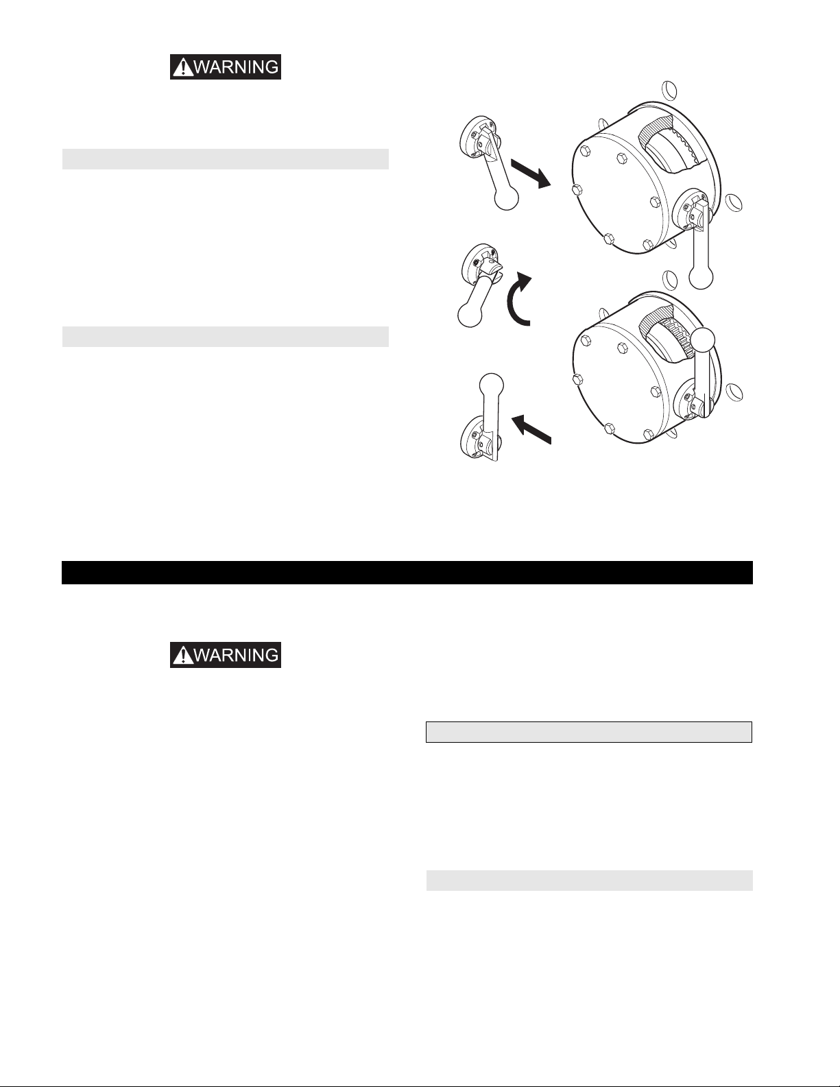
Free Spool (optional feature)
Refer to Dwg. MHP2414 on page 61.
The Free Spool option allows wire rope to be spooled from the
drum without operating winch motor.
During normal winch operations the free spool is in non-free spool
position. The output shaft connects outboard upright to drum. The
free spool handle is in the ‘DOWN’ position.
MHD56087 - Edition 4 15
-
-
• To avoid damage to mounting structure and winch, the winch
drum must be stationary and there must be no load on wire
rope during Free Spool operation.
Free Spool Position:
1. Engage drum band brake to lock drum in position.
2. Pull handle (512) out.
3. Rotate handle (512) counterclockwise, 180° to the ‘UP’
position.
4. Release handle. Ensure handle is engaged in slots in detent
plate (514).
The drum is now in free spool. During free spool operations use
drum band brake to control drum speed during wire rope payout.
Non Free Spool Position:
Free Spool Operation
Step 1.
Step 2.
Drum
Engaged
Position
Before operating winch with motor, ensure winch is not in free
spool mode.
1. Engage drum band brake.
2. Pull handle (512) out.
3. Rotate handle clockwise, 180° to the ‘DOWN’ position. This
connects winch drum to outboard upright. If required, band
brake can be released and drum slowly rotated by hand to
assist in lining up output shaft (28) splines with upright.
4. Release handle. Ensure handle is engaged in slot in detent
plate (514).
Step 3.
NOTE: Reverse prodedure
before operating winch.
(Dwg. MHP1322)
Drum
Free Spool
Position
INSPECTION
Inspection information is based in part on American National
Standards Institute Safety Codes (ASME B30.7).
WARNING
• All new, altered or modified equipment should be inspected
and tested by personnel instructed in safety, operation and
maintenance of this equipment to ensure safe operation at
rated specifications before placing equipment in service.
• Never use a winch that inspection indicates is damaged.
Frequent and periodic inspections should be performed on
equipment in regular service. Frequent inspections are visual
examinations performed by operators or personnel trained in
safety and operation of this equipment and include observations
made during routine equipment operation. Periodic inspections are
thorough inspections conducted by personnel trained in the safety,
operation and maintenance of this equipment.
ASME B30.7 states inspection intervals depend upon the nature of
the critical components of the equipment and the severity of usage.
The inspection intervals recommended in this manual are based on
intermittent operation of the winch eight hours each day, five days
per week, in an environment relatively free of dust, moisture, and
corrosive fumes. If the winch is operated almost continuously or
more than the eight hours each day, more frequent inspections will
be required.
Careful inspection on a regular basis will reveal potentially
dangerous conditions while still in the early stages, allowing
corrective action to be taken before the condition becomes
dangerous.
16 MHD56087 - Edition 4
Deficiencies revealed through inspection, or noted during
operation, must be reported to designated personnel instructed in
safety, operation and maintenance of this equipment.
A determination as to whether a condition constitutes a safety
hazard must be decided, and the correction of noted safety hazards
accomplished and documented by written report before placing
the equipment in service.
Records and Reports
Inspection records, listing all points requiring periodic inspection
should be maintained for all load bearing equipment. Written
reports, based on severity of service, should be made on the
condition of critical parts as a method of documenting periodic
inspections. These reports should be dated, signed by the person
who performed the inspection, and kept on file where they are
readily available for authorized review.
Wire Rope Reports
Records should be maintained as part of a long-range wire rope
inspection program. Records should include the condition of wire
rope removed from service. Accurate records will establish a
relationship between visual observations noted during frequent
inspections and the actual condition of wire rope as determined by
periodic inspections.
-
-
Frequent Inspection
Periodic Inspection
On equipment in continuous service, frequent inspection should
be made by operators at the beginning of each shift. In addition,
visual inspections should be conducted during regular operation
for indications of damage or evidence of malfunction (such as
abnormal noises).
1. WINCH. Prior to operation, visually inspect winch housings,
controls, brakes, side rails, uprights and drum for indications
of damage. Any discrepancies noted must be reviewed and
inspected further by authorized personnel instructed in the
operation, safety and maintenance of this winch.
2. WIRE ROPE. Visually inspect all wire rope which can be
expected to be in use during the day’s operations. Inspect for
wear and damage indicated by distortion of wire rope such as
kinking, “birdcaging,” core protrusion, main strand
displacement, corrosion, broken or cut strands. If damage is
evident, do not operate winch until discrepancies have been
reviewed and inspected further by personnel knowledgeable
on wire rope safety and maintenance procedures.
NOTICE
• The full extent of wire rope wear cannot be determined by
visual inspection. At any indication of wear inspect the wire
rope in accordance with instructions in “Periodic Inspection.”
3. AIR SYSTEM. Visually inspect all connections, fittings,
hoses and components for indication of air leaks. Repair any
leaks or damage.
4. CONTROLS. During operation of winch, verify response to
control is quick and smooth. If winch responds slowly or
controls stick, do not operate winch until all problems have
been corrected.
5. BRAKES. During winch operation test brakes. Brakes must
hold load without slipping. Automatic brakes must release
when winch motor throttle is operated. If brakes do not hold
load, or do not release properly, brakes must be adjusted or
repaired.
6. WIRE ROPE REEVING. Check reeving and ensure wire
rope is properly secured to the drum. Do not operate winch
unless wire rope feeds onto the drum smoothly.
7. LUBRICATION. Refer to “LUBRICATION” section for
recommended procedures and lubricants.
8. PENDANT (optional feature). Ensure operation of pendant
levers is smooth and that winch is responsive to pendant
control. Pendant levers must spring return to neutral position
when released.
9. MANUAL THROTTLE LEVER. Ensure operation of
manual throttle lever is smooth and winch is responsive to
lever movement. Lever must return to neutral and lock in
place when released. If winch responds slowly or controls
stick, do not operate winch until all problems have been
corrected.
10. MOTOR. During operation check motor housing for excess
heat build up. Housing should not be hot to touch. Listen for
grinding or knocking noises. Ensure lubricated air supply
provides 6 to 9 drops per minute of ISO VG 32 (SAE 10W)
oil when winch is operated at rated capacity. Operate winch
slowly in both directions to verify operation.
Periodic inspection intervals for winch use under various
conditions is listed below:
NORMAL HEAVY SEVERE
yearly semiannually quarterly
Disassembly may be required as a result of frequent inspection
findings or in order to properly inspect individual components.
Disassembly steps are described in the “MAINTENANCE”
section. Maintain written records of periodic inspections to
provide an accumulative basis for continuing evaluation. Inspect
all items listed in ‘Frequent Inspection.’ Also inspect the
following:
1. RAILS and UPRIGHTS. Check for deformed, cracked or
corroded main components. Replace damaged parts.
2. FASTENERS. Check retainer rings, split pins, capscrews,
nuts, and other fasteners on winch, including mounting bolts.
Replace if missing or damaged and tighten if loose.
3. DRUM and SHEAVES. Check for cracks, wear or damage.
Replace if necessary.
4. WIRE ROPE. In addition to ‘Frequent Inspection’
requirements, also inspect for the following:
a. Buildup of dirt and corrosion. Clean with steam or a stiff
wire brush to remove dirt and corrosion if necessary.
b. Loose or damaged end connection. Replace if loose or
damaged.
c. Check wire rope anchor is secure in drum.
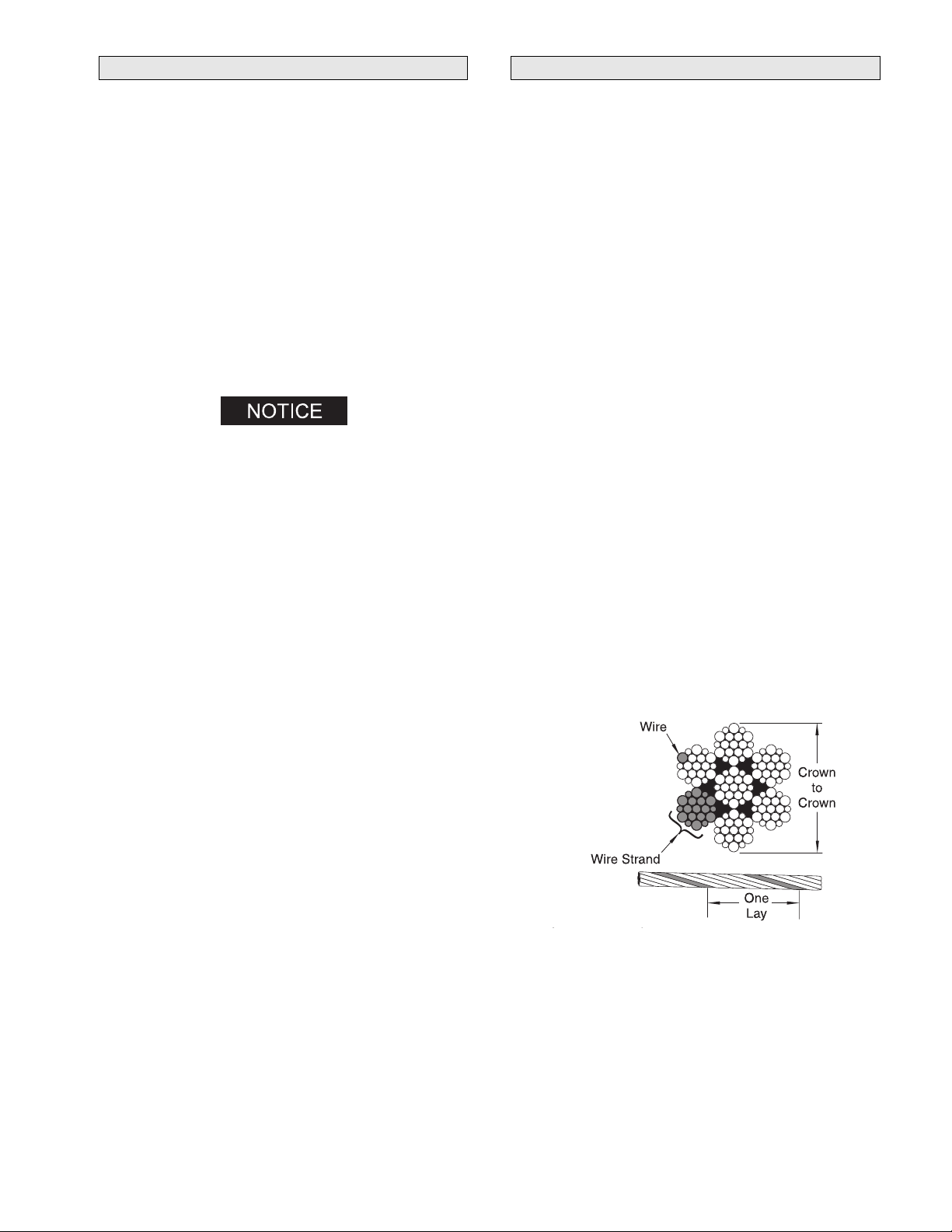
d. Verify wire rope diameter. Measure the diameter of the
wire rope from crown-to-crown throughout the life of
the wire rope. Recording of the actual diameter should
only be done with the wire rope under equivalent
loading and in the same operating section as
accomplished during previous inspections. If the actual
diameter of the wire rope has decreased more than 1/64
inch (0.4 mm) a thorough examination of the wire rope
should be conducted by an experienced inspector to
determine the suitability of the wire rope o remain in
service. Refer to Dwg. MHP0056 on page 17.
(Dwg. MHP0056)
5. ALL COMPONENTS. Inspect for wear, damage, distortion,
deformation and cleanliness. If external evidence indicates
damage, disassemble as required to conduct a detailed
inspection. Inspect gears, shafts, bearings, sheaves, springs
and covers. Replace worn or damaged parts. Clean, lubricate
and reassemble.
MHD56087 - Edition 4 17
-
-

6. BRAKES. Individually test brakes installed to ensure proper
operation. Brakes must hold a 125% rated load at mid drum
without slipping. If indicated by poor operation or visual
damage, disassemble and repair brake(s). Check all brake
surfaces for wear, deformation or foreign deposits. Clean and
replace components as necessary. Adjustments can be made
to the drum band brake to compensate for normal brake
lining wear. Refer to ‘Adjustments’ in the
“MAINTENANCE” section. If brake band cannot be
adjusted to hold rated load, replace the brake band assembly.
Adjustments cannot be made to the disc brake. The disc brake
must be repaired as described in the “MAINTENANCE”
section.
7. FOUNDATION or SUPPORTING STRUCTURE. Check for
distortion, wear and continued ability to support winch and
rated load. Ensure winch is firmly mounted and that fasteners
are in good condition and tight.
8. LABELS AND TAGS. Check for presence and legibility of
labels. Replace if damaged or missing.
9. DRUM GUARD (optional feature). Verify fasteners are tight
and in good condition. Ensure guard is in good condition.
10. EMERGENCY STOP VALVE (optional feature). During
winch operation verify the emergency shut-off valve
operation. Valve must stop winch operation quickly. Valve
must reset properly. Refer to ‘Emergency Stop Valve’ in the
“OPERATION” section for procedures.
11. OVERLOAD DEVICE (optional feature). Ensure overload
device is properly set to stop the winch when loads exceed
150% (+/- 25%) of winch rated capacity. If winch does not
shut down, contact your distributor or the factory for repair
information.
Winches Not in Regular Use
1. Equipment which has been idle for a period of one month or
more, but less than six months, shall be given an inspection
conforming to the requirements of ‘Frequent Inspection’
before being placed in service.
2. Equipment which has been idle for a period of over six
months shall be given a complete inspection conforming with
the requirements of ‘Periodic Inspection’ before being place
in service.
3. Standby equipment shall be inspected at least semiannually
in accordance with the requirements of ‘Frequent
Inspection’. In abnormal operating conditions equipment
should be inspected at shorter intervals.
18 MHD56087 - Edition 4
-
-

INSPECTION AND MAINTENANCE REPORT
Ingersoll-Rand Force 5 Series FA5A Air Winch
Model Number: Date:
Serial Number: Inspected by:
Reason for Inspection: (Check Applicable Box)
1. Scheduled Periodic Inspection:
(_____ Quarterly _____ Semiannually _____ Yearly)
2. Discrepancy(s) noted during Frequent Inspection
3. Discrepancy(s) noted during maintenance
4. Other: ___________________________
Refer to the Parts, Operation and Maintenance Manual “INSPECTION” section for general inspection criteria. Also, refer to appropriate
National Standards and Codes of practice. If in doubt about an existing condition, contact the nearest Ingersoll-Rand Distributor or the
factory for technical assistance.
COMPONENT
Uprights and
Side Rails
Drum Band Brake
(125% Load Test)
Disc Brake
(125% Load Test)
Drum Band Brake
(Visual Inspection)
Disc Brake
(Visual Inspection)
Motor
Controls
Air System
Fasteners
Reduction Gears
Labels and Tags ---
Shafts
Drum Guard
Wire Rope Wedge ---
Emergency Stop Valve
Overload Device ---
Wire Rope ---
Other Components
(list in NOTES section)
CONDITION
Pass Fail Repair Replace
CORRECTIVE
ACTION
Operating Environment:
Normal: ___ Heavy: ___ Severe: ___
NOTES
TESTING Pass Fail NOTES
Operational (No Load)
Operational (10% Load)
Operational (Maximum Test Load*)
* Maximum test load is 125% of rated line pull. Testing to more than 125% of rated load may be required to comply with standards and
regulations set forth in areas outside the USA.
This form may be copied and used as an inspection/maintenance record.
MHD56087 - Edition 4 19
-
-

TROUBLESHOOTING
This section provides basic troubleshooting information. Determination of specific causes to problems are best identified by thorough
inspections performed by personnel instructed in safety, operation and maintenance of this equipment. The chart below provides a brief
guide to common winch symptoms, probable causes and remedies.
SYMPTOM CAUSE REMEDY
Winch will not operate. No air supply to winch. Check air supply line connections and hoses.
Winch is overloaded. Reduce load to within rated capacity.
Emergency Stop Valve engaged. Reset Emergency Shut-off valve.
Shipping plugs may still be in place. Remove shipping plugs in valve.
Load continues to move
when winch is stopped.
Winch does not lift/pull
load.
Throttle lever or
pendant lever moves
but winch does not
operate.
Motor runs hot or
makes excessive noise
during operation.
Winch runs slow. Improper hose or fitting sizes. Check fittings, connections and hoses for correct size and length. Replace
Air lines freeze. Water in air supply. Install or drain air system moisture traps, moisture collecting air receivers
Throttle lever hard to
actuate, or lever does
not spring return to
neutral.
Brake(s) slipping. Check brake band adjustment and brake band lining wear. Disassemble and
inspect disc brake. Refer to “MAINTENANCE” section on page 24.
Winch motor controls sticking. Check pendant/throttle levers spring return to normal (neutral) position when
released.
Winch is overloaded. Reduce load to within rated capacity.
Motor may be damaged. Remove and disassemble motor. Examine all parts and replace any that are
worn or damaged.
Winch is overloaded. Reduce load to within rated capacity.
Insufficient air supply. Verify air supply pressure and volume at winch inlet meets the requirements.
Refer to “SPECIFICATIONS” section on page 5. Clean air line filter.
Motor may be damaged. Disassemble and clean the motor and replace any broken or damaged parts.
Insufficient air supply. Ensure the air pressure at the winch inlet is at least 90 psig (6.3 bar/630 kPa)
at rated volume. Clean air line filter.
Air leak. Check hose and fitting connections. Inspect hose(s) for breaks. Tighten
fittings and repair or replace hoses as necessary.
Emergency Stop Valve engaged. Reset Emergency Shut-off valve.
Low oil level. Check oil levels in the motor. Add oil as required to obtain the proper level.
Improper lubrication. Replace oil with type recommended in “LUBRICATION” section on page
21. Set lubricator to provide 6 to 9 drops of oil per minute at maximum
winch operating capacity.
Water in oil. Drain and refill with recommended oil. Operate winch with no load slowly,
in both directions. If noise still exists or motor overheats disassemble and
repair motor.
Damaged or broken piston or
connecting rod.
Motor may be damaged. Remove and disassemble motor. Inspect all parts and replace all worn or
Brake(s) not releasing. Refer to brakes in “MAINTENANCE” section on page 24.
Valve body sticking in bushing. Lubricate valve through grease fitting with recommended lubricant. Refer to
Disassemble and repair motor.
parts that may cause restricted air flow. Inspect air line filter.
damaged parts.
and compressor aftercoolers. After corrective action has been taken,
disconnect lines at winch inlet and purge with clean, dry air or nitrogen.
‘Air Throttle’ on page 22 in “LUBRICATION” section.
20 MHD56087 - Edition 4
-
-

TROUBLESHOOTING (CONTINUED)
Automatic Band Brake:
Brake cylinder will not
release.
Automatic Disc Brake:
Brake fails to release. Low air supply pressure. Ensure air pressure at inlet to disc brake is at least 50 psig (3.4 bar/340 kPa).
Band brake out of adjustment. Adjust band brake to maintain correct cylinder stroke.
Leaking cylinder seals. If air is noticed escaping from cinder breather when attempting to release
brake, replace or repair cylinder.
Dirty filter in air supply. Clean or replace filter.
Faulty dump valve. Check dump valve exhaust port. Air should exhaust when control valve
handle is neutral. If no air escapes, replace dump valve.
Leaking piston seals. Inspect brake breather. If air escapes from brake breather when attempting to
release brake, replace brake seals.
No release pressure at brake port. Check for proper operation of winch controls.
Sticking brake piston. Apply 50 psig (3.4 bar/340 kPa) to brake release port and check for brake
disc movement. (Brake discs can be viewed through brake breather hole.)
If brake discs do not move, disassemble and inspect disc brake as described
in “MAINTENANCE” section.
LUBRICATION
To ensure continued satisfactory operation of the winch, all points
requiring lubrication must be serviced with correct lubricant at the
proper time interval as indicated for each assembly.
Lubrication intervals recommended in this manual are based on
intermittent operation of winch, eight hours each day, five days per
week. If winch is operated almost continuously or more than eight
hours each day, more frequent lubrication will be required. Also,
lubricant types and change intervals are based on operation in an
environment relatively free of dust, moisture, and corrosive fumes.
Use only those lubricants recommended. Other lubricants may
affect performance of winch. Approval for the use of other
lubricants must be obtained from your Ingersoll-Rand distributor.
Failure to observe this precaution may result in damage to the
winch and its associated components.
INTERVAL LUBRICATION CHECKS
Start of each
shift
Monthly Lubricate components supplied by grease
Yearly Drain and refill winch reduction gear oil.
Check flow and level of air line lubricator
(approximately 6 to 9 drops per minute required
at maximum motor speed).
Check winch motor oil level.
fittings.
Inspect and clean or replace air line filter.
Check reduction gear oil level.
Drain and refill winch motor oil.
2. Always inspect removed oil for evidence of internal damage
or contamination (metal shavings, dirt, water, etc.). If
indications of damage are noted, investigate and correct
before returning winch to service.
3. After winch operation, allow oil to settle before topping off.
4. Always collect lubricants in suitable containers and dispose
of in an environmentally safe manner.
Reduction Gear and Disc Brake Lubrication
Refer to Dwg. MHP0501 on page 22.
The reduction gear and disc brake are filled and shipped with oil
from the factory. Check oil level before initial winch operation.
These components are splash lubricated by the oil in the housing
and have no other means of lubrication. It is therefore important to
use high quality Extreme Pressure (EP) rust and oxidation
inhibited gear oils to ensure maximum performance and minimum
down time for repairs. Oil capacity is approximately 3 quarts (2.8
litres). Oil from the reduction gear assembly also provides
lubrication for the disc brake.
On winches equipped with a disc brake, the reduction gear is
vented through the disc brake breather plug.
Recommended Lubricant
Temperature Type Oil
Below 32° F (0° C) ISO VG 68 (SAE 2 EP)
32° to 80° F (0° to 27° C) ISO VG 100 (SAE 3 EP)*
Above 80° F (27° C) ISO VG 150 (SAE 4 EP)
Note: Intervals are based on winch operation in a normal
environment as described in “INSPECTION” section. In ‘Heavy’
or ‘Severe’ operating conditions adjust lubrication intervals
accordingly.
General Lubrication
1. Drain and replace oil in the motor, disc brake and reduction
gear after the first 50 hours of initial winch operation.
Thereafter, drain and replace oil according to intervals
recommended.
MHD56087 - Edition 4 21
* Units are shipped from factory with ISO VG 100 (SAE 3 EP)
lubricant. Reduction Gear capacity is approximately 3 quarts
(2.8 litres).
Recommended Grease
Temperature Type Grease
-20° to 50° F
(-30° to 10° C)
30° to 120° F
(-1° to 49° C)
-
-
EP 1 multipurpose
lithium based grease
EP 2 multipurpose
lithium based grease
 Loading...