


Ingersoll-Rand 65665B, 65666, 66620, 656652B, 65662 User Manual
...OPERATOR’S MANUAL |
|
6564X-X |
|
|
6566X-X |
INCLUDING: OPERATION, INSTALLATION & MAINTENANCE |
|
|
6” AIR MOTORS |
|
66620 |
6564X-X and 66620 |
6566X-X |
RELEASED: 8-28-91 |
REVISED: 10-11-01 |
||
4” STROKE |
6” STROKE |
(REV. K) |
|
READ THIS MANUAL CAREFULLY BEFORE INSTALLING,
OPERATING OR SERVICING THIS EQUIPMENT.
THIS MANUAL COVERS THE FOLLOWING MODELS
|
|
|
MODEL |
|
|
|
|
65643 |
65662 |
|
65665 2B |
66620 |
|
|
|
|
|
|
|
|
|
65645 |
65665 B |
|
65666 |
|
|
|
|
|
|
|
|
|
SERVICE KITS
61355 for general repair of all 6" air motors.
GENERAL DESCRIPTION
The 6" air motor is a general purpose power unit and is used with many 2 ball, 4 ball and chop check pumps. It utilizes tie rod type construction for easy breakdown and it connects to the various lower ends via tie rods for easy operation. Consult pump model operator's manual for specific instructions. It is recommended that a muffler be connected to the ex haust port to reduce noise to acceptable OSHA standards.
Filtered and oiled air will allow the air motor to operate more efficiently and yield a longer life to operating parts and mechanisms. A filter capa ble of filtering particles larger than 50 microns should be used with an oiler. Keep the oiler supplied with a good grade of S.A.E. no. 90W non detergent gear oil, set at a rate not to exceed 1 or 2 drops per minute.
NOTICE
DO NOT OPERATE AIR MOTOR ABOVE RECOMMENDED
AIR PRESSURE OF 150 P.S.I. (10.3 BAR) OR 75 CYCLES PER
MINUTE. Air motor may be rated differently in the next assembly.
Check model plate.
INGERSOLL-RAND COMPANY
P.O. BOX 151 D ONE ARO CENTER D BRYAN, OHIO 43506 0151
& (419) 636-4242 D FAX (419) 633-1674 E2001 D PRINTED IN U.S.A.
AIR MOTOR PARTS LIST
n PARTS SO MARKED ARE INCLUDED IN 61355 SERVICE KIT.
REF. |
DESCRIPTION (SIZE IN INCHES) |
QTY |
PART NO. |
|
V 1 |
Machine Screw (#8 32 x 7/8") |
4 |
Y136 90 S |
|
|
|
|
|
|
V 2 |
Deflector |
1 |
90409 |
|
|
|
|
|
|
|
Deflector (model 65665 2B) |
1 |
90409 1 |
|
V 3 |
Screw (#10 24 x 1/2") |
6 |
95956827 |
|
|
|
|
|
|
n V 4 |
Machine Screw (#8 32 x 3/4") |
8 |
Y19 89 S |
|
n 5 |
Washer |
8 |
90084 |
|
|
|
|
|
|
V 6 |
Machine Screw (1/4" 28 x 3/4") |
2 |
Y119 49 C |
|
|
|
|
|
|
7 |
Lock Washer (1/4" i.d.) |
2 |
Y14 416 |
|
V 8 |
Air Motor Cap |
1 |
90078 |
|
|
|
|
|
|
|
Air Motor Cap (model 65665 2B) |
1 |
90078 5 |
|
V 9 |
Valve Guide |
1 |
90488 |
|
|
|
|
|
|
n 10 |
Gasket |
1 |
90083 1 |
|
|
|
|
|
|
V 11 |
Valve Plate and Pin Assembly |
1 |
65756 |
|
V 12 |
Insert Spring Assembly |
1 |
65807 |
|
|
|
|
|
|
n 13 |
Valve Insert |
1 |
99202 |
|
n 14 |
Valve Plate Gasket |
1 |
90479 |
|
|
|
|
|
|
n 15 |
•O" Ring (1/16" x 1 3/8" o.d.) |
2 |
Y325 26 |
|
|
|
|
|
|
n 16 |
Washer |
1 |
91344 |
|
n 17 |
•O" Ring (1/16" x 7/8" o.d.) |
2 |
Y325 18 |
|
|
|
|
|
|
18 |
Head Assembly |
1 |
65890 |
|
|
Head Assembly (model 65665 2B) |
1 |
65890 3 |
|
|
|
|
|
|
n 19 |
•U" Cup (3/16" x 1 3/8" o.d.) |
1 |
Y186 51 |
|
|
|
|
|
|
n 20 |
•O" Ring (1/8" x 6" o.d.) |
2 |
Y325 256 |
|
n 21 |
Machine Screw (#8 32 x 3/8") |
4 |
Y136 85 S |
|
|
|
|
|
|
22 |
Adapter |
1 |
90111 |
|
V 23 |
Piston Assembly |
1 |
61419 |
|
|
|
|
|
|
V 24 |
•O" Ring (1.191" o.d.) |
1 |
90085 |
|
|
|
|
|
|
25 |
Nut |
1 |
90112 |
|
|
REF. |
DESCRIPTION (SIZE IN INCHES) |
QTY |
PART NO. |
|
V 26 |
Valve Rod |
|
See chart, page 4 |
||
|
|
|
|
|
|
V 27 |
Air Cylinder |
|
See chart, page 4 |
||
|
|
|
|
|
|
28 |
Tube |
|
See chart, page 4 |
||
|
|
|
|
|
|
n 29 |
•O" Ring |
|
See chart, page 4 |
||
|
|
|
|
|
|
30 |
Air Motor Base Assembly |
|
See chart, page 4 |
||
n 31 |
Valve Piston |
1 |
92395 |
|
|
|
|
|
|
|
|
n 32 |
Valve Plate Gasket |
1 |
90482 |
|
|
|
|
|
|
|
|
V 33 |
Valve Plate |
1 |
90480 |
|
|
n 34 |
Pilot Insert |
1 |
90487 |
|
|
|
|
|
|
|
|
V 35 |
Valve Guide |
2 |
90481 |
|
|
n 36 |
Washer |
1 |
90105 |
|
|
|
|
|
|
|
|
V 37 |
Upper Gland |
1 |
91006 |
|
|
|
|
|
|
|
|
n 38 |
Seal |
1 |
91007 |
|
|
n 39 |
•O" Ring (.103" x 1.255" o.d.) |
1 |
91207 |
|
|
|
|
|
|
|
|
V 40 |
Extension Rod |
1 |
90080 |
|
|
41 |
Ground Lug |
1 |
93006 |
|
|
|
|
|
|
|
|
n 42 |
Piston Adapter |
1 |
92393 |
|
|
|
|
|
|
|
|
V 43 |
Lower Gland |
1 |
90114 |
|
|
n 44 |
Washer |
1 |
91345 |
|
|
|
|
|
|
|
|
n 45 |
•O" Ring (1/16" x 7/16" o.d.) |
1 |
Y325 11 |
|
|
46 |
Bolt |
|
See chart, page 4 |
||
|
|
|
|
|
|
V 47 |
Retaining Ring |
|
See chart, page 4 |
||
|
|
|
|
|
|
V 48 |
Guide Washer |
|
See chart, page 4 |
||
|
|
|
|
|
|
n 49 |
•U" Cup |
|
See chart, page 4 |
||
|
|
|
|
|
|
50 |
Nut |
|
See chart, page 4 |
||
|
|
|
|
|
|
V 51 |
Washer |
|
See chart, page 4 |
||
|
|
|
|
|
|
V 52 |
Piston Rod |
|
See chart, page 4 |
||
|
|
|
|
|
|
V •Smart Parts", Keep these items on hand in addition to the service kits for fast repair and reduction of downtime.
DISASSEMBLY OF AIR MOTOR
NOTE: ALL THREADS ARE RIGHT HAND.
1.Force the (23) piston assembly up by pushing the (52) piston rod to ward the top of the air motor.
2.Remove the four (1) machine screws from the (2) deflector.
3.Remove the (2) deflector.
4.Remove the six (3) screws from the (8) air motor cap.
5.Remove the (8) air motor cap and (10) gasket.
6.Loosen the eight (4) machine screws (which hold the (11) valve plate and pin assembly, (9) valve guide, two (35) valve guides and the (33) valve plate) until the (9 and 35) valve guides can be removed by pull ing upward (see figure 9).
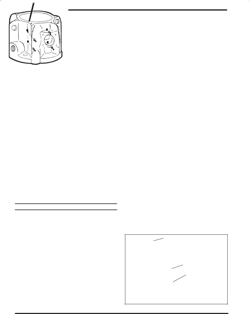
7.Remove the eight (4) machine screws and eight (5) washers from the 6" air motor by pressing outward with a small allen wrench (see figures 1 and 9).
8.With a screwdriver, unhook the (12) insert spring assembly from the bottom of the (11) valve plate and pin assembly.
9.Remove the (12) insert spring assembly from the pins in the top of the (11) valve plate and pin assembly.
10.Remove the (11) valve plate and pin assembly and (33) valve plate by pulling upward. If they are stuck, tap the top edge lightly with a soft face hammer or screwdriver handle (do not tap with anything metal lic).
11.Remove the (13) valve insert and the (34) pilot insert.
12.Remove the (32 and 14) gaskets.
13.Remove the (12) insert spring assembly.
14.Remove the two (6) machine screws and the two (7) lock washers from the (37) upper gland (see figure 9).
15.Pull the (31) valve piston upward until the (37) upper gland has pulled out of its chamber.
ALLEN WRENCH
(USE AN ALLEN WRENCH TO PUSH OUT SCREWS & WASHERS AS SHOWN.)
4 SCREWS (8)
5 WASHERS (8)
(THE REMAINING FOUR WASHERS AND SCREWS ARE ON THE OPPOSITE SIDE.)
PAGE 2 OF 8 |
6564X X |

|
6 |
|
7 |
41 |
1 |
4 |
2 |
3 |
|
5 |
31 |
|
|
|
32 |
|
33 |
|
34 |
Q |
35 |
|
36 |
|
37 |
|
39 |
|
38 |
|
42 |
|
40 |
|
44 |
|
43 |
Q |
45 |
Q NOTE: LUBRICATE WITH PARKER |
FIGURE 2 |
‘‘O” RING LUBE (ARO P/N 36460). |
|
31
42
AIR MOTOR HEAD
PART NUMBERS LISTED BELOW AND ON PARTS LIST (OPPOSITE PAGE) ARE TYPICAL.
9
8
10
11
12
13
14
15 Q
16
18
17
19 Q 
20 Q
21
23
22
24
25
6564X X |
PAGE 3 OF 8 |
 Loading...