


210CSA
Paint Sprayer
Models 200G, 210G, 270G and 210CSA
Product Information
EN
Product Information
ES
Especicaciones del producto
FR
Spécications du produit
47083068
Edition 1
December 2009
Save These Instructions
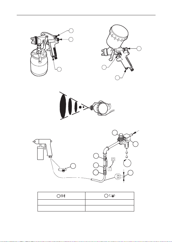
MODEL 210CSA MODEL 200G, 210G and 270G
3
1
2
1
3
2
3
7
4
2
1
48h
5
6
4
5
(Dwg. 47083233)
(Dwg. TP2051)
(Dwg. 16577629)
inch (mm) NPS (inch)
2 47083068_ed1
5/16 (8) 1/4
EN
WARNING
NOTICE
Fan Direction
Air Cap
Lock Ring
Product Safety Information
Intended Use:
Paint Sprayers are designed for paint, lacquer, stain or other nish type material.
For additional information refer to Product Safety Information Manual Form 16576563.
Manuals can be downloaded from www.ingersollrandproducts.com.
Product Specications
Model Description
Touch-Up Gravity
200G
Feed Spray Gun
Gravity Feed
210G
Spray Gun
HVLP Gravity
270G
Feed Spray Gun
Suction Feed
210CSA
Spray Gun
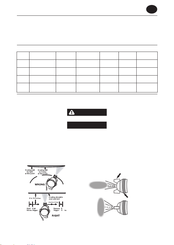
Operations
Spray Gun Handling
Do not point the spray gun at anyone or at any part of the body.
Ensure appropriate air line lter is being used. Water, oil, and debris in the air may cause
damage to the workpiece.
The spray gun should be held perpendicular to the work surface and 6 to 12 inches from the
work surface. Keep the gun parallel to the work surface during the stroke to ensure even coating.
DO NOT move the gun in an arc. This will result in a build up of paint in the center of the stroke
and a light coating at each end.
Start the gun moving prior to pulling the trigger and release the trigger before stopping the gun
movement. Overlap strokes enough to get a uniform nish.
Maximum
Air Pressure
35 psig
[2.4 bar]
60 psig
[4.1 bar]
40 psig
[2.8 bar]
60 psig
[4.1 bar]
Average Air
Consumption
5 cfm
[140 l/min]
11 cfm
[300 l/min]
8 cfm
[235 l/min]
12 cfm
[340 l/min]
Tool
Weight
1.2 lbs
[0.52 kg]
2.6 lbs
[1.2 kg]
2.7 lbs
[1.3 kg]
1.5 lbs
[0.62 kg]
Cup
Capacity
4.2 oz
[125 cc]
20 oz
[600 cc]
33 oz
[1,000 cc]
33 oz
[1,000 cc]
Fluid
Nozzle Size
0.03 in
[0.8 mm]
0.05 in
[1.4 mm]
0.06 in
[1.5 mm]
0.07 in
[1.8 mm]
(Dwg. TP2049)
47083068_ed1 EN-1
(Dwg. TP2053)
EN
WARNING
NOTICE
WARNING
WARNING
Always turn o the air supply and disconnect the air supply hose before installing, removing or adjusting any accessory on this tool, or before performing any maintenance on this
tool.
The direction of the fan can be adjusted from horizontal to vertical be loosening the lock ring
and turning the air cap to the proper location. Hand tighten lock ring after adjustment.
Controls
Refer to illustration 47083233 on page 2.
1. Fluid Control
The uid control knob will adjust the atomization of the paint. Turn the knob clockwise until fully
closed. Then while turning the knob
counterclockwise, trigger short bursts of paint. This counterclockwise movement of the knob will
move the pattern from ne to coarse. Adjust the knob until the desired pattern is obtained.
2. Pattern Control
The pattern control knob adjusts the size of the fan. A wide fan will result if the knob is fully
opened by turning it counterclockwise. As the knob is turned clockwise, a smaller round pattern
will be achieved.
3. Air Control (If Applicable)
Open the air control knob fully by turning counter clockwise. Set desired air pressure using
regulator. Do not exceed maximum air pressure. If a lower air pressure is desired for some parts
of the spray job, turn the air control knob clockwise as needed.
Spray Patterns
If the pattern is too coarse and the uid control knob can not adjust it properly, try adjusting the
air pressure or thin the paint to achieve
desired pattern.
The spray pattern varies from round to at with patterns in between (Refer to illustration TP2051
on Page 2).
Routine Maintenance
Dispose of hazardous uid according to all local, state, and national guidelines.
Always turn o the air supply and disconnect the air supply hose before installing, removing or adjusting any accessory on this tool, or before performing any maintenance on this
tool.
Clean spray gun and canisters immediately after use. Paint or other uids can dry quickly and can
easily plug internal passageways and render the spray gun useless.
Do not use Methylene chloride (Dichloromethane) or any halogenated hydrocarbon
solvents with this spray gun.
EN-2 47083068_ed1

EN
NOTICE
NOTICE
Remove and empty the canister. Rinse canister with a solvent recommended for the paint being
used.
Fill canister with solvent and attach to spray gun. Spray solvent into an approved container, while
shaking the gun vigorously. Continue until all traces of paint have been eliminated from spray.
Also wipe the exterior of the gun with a rag soaked with the solvent.
Remove the air cap and soak in solvent. Use a toothpick or plastic brush, to clean air passages.
Using metal objects can damage the precision air passages. DO NOT soak spray gun in
solvent. This can damage non-metallic
components.
After cleaning, lubricate lightly with NON-SILICONE OIL. Silicone oil can cause oil spots to
occur in the paint.
Installation and Lubrication
Size air supply line to ensure tool’s maximum operating pressure (PMAX) at tool inlet. Drain
condensate from valve(s) at low point(s) of piping, air lter and compressor tank daily. Install a
properly sized Safety Air Fuse upstream of hose and use an anti-whip device across any hose
coupling without internal shut-o, to prevent hose whipping if a hose fails or coupling disconnects. See drawing 16577629 and table on page 2. Maintenance frequency is shown in circular
arrow and dened as h=hours, d=days, and m=months of actual use.. Items identied as:
1. Air lter 5. Thread size
2. Regulator 6. Coupling
3. Emergency shut-o valve 7. Safety Air Fuse
4. Hose diameter
Parts and Maintenance
When the life of the tool has expired, it is recommended that the tool be disassembled, degreased and parts be separated by material so that they can be recycled.
The original language of this manual is English.
Tool repair and maintenance should only be carried out by an authorized Service Center.
Refer all communications to the nearest Ingersoll Rand Oce or Distributor.
47083068_ed1 EN-3
 Loading...