


This manual contains important safety information and must be made available to personnel who operate and maintain this machine.
7/120, 9/110, 10/105, 14/85 7/170, 10/125, 14/115
OPERATION AND MAINTENANCE MANUAL
7/120 |
9/110 |
|
|
10/105 14/85 |
SERIAL No : |
320001 –> |
|
7/170 |
10/125 |
14/115 |
|
|
|
|
|
C.C.N. : 22191225 GB
DATE : SEPTEMBER 2003

Machine models represented in this manual may be used in various locations world–wide. Machines sold and shipped into European Union Territories require that the machine display the EC Mark and conform to various directives. In such cases, the design specification of this machine has been certified as complying with EC directives. Any modification to any part is absolutely prohibited and would result in the CE Certification and marking being rendered invalid. A declaration of that conformity follows:
DECLARATION OF CONFORMITY WITH EC DIRECTIVES
98/37/EC, 93/68/EEC, 89/336/EEC We
Ingersoll–Rand Company |
Represented in EC by: |
Ingersoll–Rand Company Limited |
P.O. Box 868 |
|
Swan Lane |
501 Sanford Avenue |
|
Hindley Green |
Mocksville, North Carolina 27028 |
|
Wigan WN2 4EZ |
|
|
United Kingdom |
Declare that, under our sole responsibility for manufacture and supply, the product(s)
7/120 (P425AWIR) 9/110 (XP375AWIR) 10/105 (HP375AWIR) 14/85 (VHP300AWIR)
to which this declaration relates, is (are) in conformity with the provisions of the above directives using the following principal standards
EN29001 : EN292, EN60204–1, EN1012–1, PN8NTC2, EN50081, EN50082
Issued at Mocksville on |
Issued at Hindley Green on |
1–1–2003 |
1–1–2003 |
________________________________ |
|
Ric Lunsford |
Harry Seddon |
Manager of quality control |
Quality assurance manager |
CONFORMITY WITH NOISE DIRECTIVE 2000/14/EC
Ingersoll–Rand Company Limited declare that the following Portable Compressors have been manufactured in conformity with the directive as shown
|
Directive |
Machine |
|
Mean |
|
Guaranteed |
Notified body |
|||
|
|
|
|
measured |
|
|||||
|
Type |
kW |
|
Level |
||||||
|
|
value |
|
|
|
|||||
|
2000/14/EC |
14/85WIR |
|
|
|
|
|
|
A V Technology |
|
|
10/105WIR |
|
93 |
100.2 LWA |
|
101 LWA |
||||
|
Annex VI |
|
|
|
Stockport UK |
|||||
|
9/110WIR |
|
|
|||||||
|
Part I |
|
|
|
|
|
|
|
Nr 1067 |
|
|
|
7/120WIR |
|
|
|
|
|
|
|
|
|
|
|
|
|
|
|
|
|||
|
|
|
|
|
|
________________________________ |
|
|||
|
Issued at . . . . . . . . . Mocksville, NC |
|
|
|
|
|
|
|||
|
|
|
|
Ric Lunsford |
|
|
||||
|
1st Declaration . . . . January 11, 2003 |
|
|
|
|
|
||||
|
|
|
Manager of quality control |
|||||||
EC Pressure Equipment Directive and Related Regulations
We declare that this product has been assessed according to the Pressure Equipment Directive (97/23/EC) and, in accordance with the terms of this Directive, has been excluded from the scope of this Directive. It may carry ”CE” marking in compliance with other applicable EC Directives.
Machine models represented in this manual may be used in various locations world–wide. Machines sold and shipped into European Union Territories require that the machine display the EC Mark and conform to various directives. In such cases, the design specification of this machine has been certified as complying with EC directives. Any modification to any part is absolutely prohibited and would result in the CE Certification and marking being rendered invalid. A declaration of that conformity follows:
DECLARATION OF CONFORMITY WITH EC DIRECTIVES
98/37/EC, 93/68/EEC, 89/336/EEC We
Ingersoll–Rand Company |
Represented in EC by: |
Ingersoll–Rand Company Limited |
P.O. Box 868 |
|
Swan Lane |
501 Sanford Avenue |
|
Hindley Green |
Mocksville, North Carolina 27028 |
|
Wigan WN2 4EZ |
|
|
United Kingdom |
Declare that, under our sole responsibility for manufacture and supply, the product(s)
7/170 (P600WIR) 10/125 (HP450WIR) 14/115 (VHP400WIR)
to which this declaration relates, is (are) in conformity with the provisions of the above directives using the following principal standards
EN29001 : EN292, EN60204–1, EN1012–1, PN8NTC2, EN50081, EN50082
Issued at Mocksville on |
Issued at Hindley Green on |
1–1–2003 |
1–1–2003 |
________________________________ |
|
Ric Lunsford |
Harry Seddon |
Manager of quality control |
Quality assurance manager |
CONFORMITY WITH NOISE DIRECTIVE 2000/14/EC
Ingersoll–Rand Company Limited declare that the following Portable Compressors have been manufactured in conformity with the directive as shown
|
Directive |
Machine |
|
Mean |
|
Guaranteed |
Notified body |
|||
|
|
|
|
measured |
|
|||||
|
Type |
kW |
|
Level |
||||||
|
|
value |
|
|
|
|||||
|
2000/14/EC |
14/115 |
|
|
|
|
|
|
A V Technology |
|
|
Annex VI |
10/125 |
|
126.5 |
100.2 LWA |
|
101 LWA |
Stockport UK |
||
|
Part I |
|
|
|
|
|
|
|
Nr 1067 |
|
|
7/170 |
|
|
|
|
|
|
|||
|
|
|
|
|
|
|
|
|||
|
|
|
|
|
|
________________________________ |
|
|||
|
Issued at . . . . . . . . . Mocksville, NC |
|
|
|
|
|
|
|||
|
|
|
|
Ric Lunsford |
|
|
||||
|
1st Declaration . . . . January 11, 2003 |
|
|
|
|
|
||||
|
|
|
Manager of quality control |
|||||||
EC Pressure Equipment Directive and Related Regulations
We declare that this product has been assessed according to the Pressure Equipment Directive (97/23/EC) and, in accordance with the terms of this Directive, has been excluded from the scope of this Directive. It may carry ”CE” marking in compliance with other applicable EC Directives.
1CONTENTS
2FOREWORD
3WARRANTY
9 |
DECALS |
13 |
SAFETY |
16GENERAL INFORMATION
Dimensions Data
21OPERATING INSTRUCTIONS
Commissioning Prior to starting Starting Stopping
Emergency stopping Re–starting
Monitoring during operation Decommissioning
29 ENGINE INSTRUCTION MANUAL
46MAINTENANCE
Routine maintenance Lubrication
Speed & pressure regulation Torque settings table Compressor lubrication
58MACHINE SYSTEMS
Electrical system
Piping & instrumentation system
61 SERVICE TOOLS
65 FAULT FINDING
67 OPTIONS
70 PARTS ORDERING
ABBREVIATIONS & SYMBOLS
#### Contact Ingersoll–Rand for serial number
–>#### Up to Serial No.
####–> From Serial No.
*Not illustrated
† |
Option |
AR |
As required |
D |
Germany |
DK |
Denmark |
ESpain
FFrance
GB |
Great Britain |
HA |
High ambient machine |
I |
Italy |
N |
Norway |
NL |
Netherlands |
P |
Portugal |
S |
Sweden |
SF |
Finland |
F.H.R.G. Fixed height running gear V.H.R.G. Variable height running gear
1 |
7/120 (P425AWIR), 9/110 (XP375AWIR), 10/105 (HP375AWIR), 14/85 (VHP300AWIR), |
7/170 (P600WIR), 10/125 (HP450WIR), 14/115 (VHP400WIR) |

FOREWORD
The contents of this manual are considered to be proprietary and confidential to Ingersoll–Rand and should not be reproduced without the prior written permission of Ingersoll–Rand.
Nothing contained in this document is intended to extend any promise, warranty or representation, expressed or implied, regarding the Ingersoll–Rand products described herein. Any such warranties or other terms and conditions of sale of products shall be in accordance with the standard terms and conditions of sale for such products, which are available upon request.
This manual contains instructions and technical data to cover all routine operation and scheduled maintenance tasks by operation and maintenance staff. Major overhauls are outside the scope of this manual and should be referred to an authorised
Ingersoll–Rand service department.
The design specification of this machine has been certified as complying with EC directives. As a result:
(a)Any machine modifications are strictly prohibited, and will invalidate EC certification.
(b)A unique specification for USA/Canada is adopted and tailored to the territory.
All components, accessories, pipes and connectors added to the compressed air system should be:
. of good quality, procured from a reputable manufacturer and, wherever possible, be of a type approved by Ingersoll–Rand.
. clearly rated for a pressure at least equal to the machine maximum allowable working pressure.
. compatible with the compressor lubricant/coolant.
. accompanied with instructions for safe installation, operation and maintenance.
Details of approved equipment are available from Ingersoll–Rand Service departments.
The use of repair parts / lubricants / fluids other than those included within the Ingersoll–Rand approved parts list may create hazardous conditions over which Ingersoll–Rand has no control. Therefore Ingersoll–Rand cannot be held responsible for equipment in which non–approved repair parts are installed.
Ingersoll–Rand reserves the right to make changes and improvements to products without notice and without incurring any obligation to make such changes or add such improvements to products sold previously.
The intended uses of this machine are outlined below and examples of unapproved usage are also given, however Ingersoll–Rand cannot anticipate every application or work situation that may arise.
IF IN DOUBT CONSULT SUPERVISION.
This machine has been designed and supplied for use only in the following specified conditions and applications:
. Compression of normal ambient air containing no known or detectable additional gases, vapours. or particles
. Operation within the ambient temperature range specified in the GENERAL INFORMATION section of this manual.
UNITS MANUFACTURED IN NORTH AMERICA: Generation of electricity at 120V (1ph) at 60 Hertz.
UNITS MANUFACTURED IN EUROPE: Generation of electricity not applicable.
The use of the machine in any of the situation types listed in table 1:–
a)Is not approved by Ingersoll–Rand,
b)May impair the safety of users and other persons, and
c)May prejudice any claims made against Ingersoll–Rand.
TABLE 1
Use of the machine to produce compressed air for:
a)direct human consumption
b)indirect human consumption, without suitable filtration and purity checks.
Use of the machine outside the ambient temperature range specified in the GENERAL INFORMATION SECTION of this
manual.
This machine is not intended and must not be used in potentially explosive atmospheres, including situations where flammable gases or vapours may be present.
Use of the machine fitted with non Ingersoll–Rand approved components / lubricants / fluids.
Use of the machine with safety or control components missing or disabled.
Use of the machine for storage or transportation of materials inside or on the enclosure except when contained within the toolbox.
GENERATOR
Use of the generator to supply load(s) greater than those
specified.
Use of unsafe or unserviceable electrical equipment
connected to the generator.
Use of electrical equipment:
(a)Having incorrect voltage and/or frequency ratings.
(b)Containing computer equipment and/or similar electronics.
The company accepts no responsibility for errors in translation of this manual from the original English version.
COPYRIGHT 2003
INGERSOLL–RAND COMPANY
7/120 |
(P425AWIR), 9/110 |
(XP375AWIR), 10/105 (HP375AWIR), 14/85 (VHP300AWIR), |
2 |
7/170 |
(P600WIR), 10/125 |
(HP450WIR), 14/115 (VHP400WIR) |
WARRANTY
Ingersoll–Rand, through its distributor, warrants that each item of equipment manufactured by it and delivered hereunder to the initial user will be free of defects in material and workmanship.
With respect to the following types of equipment, the warranty period enumerated below will apply.
A.Aftercoolers – The earlier of nine (9) months from date of shipment to or six (6) months from start up by initial user.
B.Portable Compressors, Portable Generator Sets (GENSET), Portable Light Towers and Air Dyers – The earlier of twelve (12) months from shipment to or the accumulation of 2,000 hours of service by the initial user.
C.Portable Compressor Air Ends – The earlier of twenty–four (24) months from shipment to or the accumulation of 4,000 hours of service by the initial user. For Air Ends, the warranty against defects will include replacement of the complete Air End, provided the original
Air End, is returned assembled and unopened.
C.1 Portable Compressor Airend Limited Optional Warranty– The earlier of sixty (60) months from shipment to or the accumulation of 10,000 hours of service. The optional warranty is limited to defects in rotors, housings, bearings and gears and provided all the following conditions are met:
The original airend is returned assembled and unopened.
Continued use of genuine Ingersoll–Rand parts, fluids, oils and filters.
Maintenance is performed at prescribed intervals.
D.Genset Generators – The earlier of twenty–four (24) months from shipment to or the accumulation of 4,000 hours of service by the initial user.
E.Portable Light Tower Generators – The earlier of twelve
(12)monthsfrom shipment to or the accumulation of 2,000 hours of service by the initial user. Light Source model only, the earlier of twenty–four (24) months from shipment to or the accumulation of 4,000 hours of service.
F.Ingersoll–Rand Engines – The earlier of twenty— four
(24)months from shipment to or the accumulation of 4,000 hours of service.
G.Ingersoll–Rand Platinum Drive Train Warranty (Optional) – Platinum drive train pertains to the
Ingersoll–Rand Engine and Airend combination. The earlier of sixty (60) months from shipment to, or the accumulation of 10,000 hours of service. The starter, alternator, fuel injection system and all electrical components are excluded from the extended warranty. The airend seal and drive coupling are included in the warranty (air–end drive belts are not included). The optional warranty is automatically available when meeting the following conditions:
The original airend is returned assembled and unopened.
Continued use of genuine Ingersoll–Rand parts, fluids, oil and filters.
Maintenance is performed at prescribed intervals.
It is the obligation of the user to provide verification that these conditions have been satisfied when submitting warranty claims.
H.Spare Parts – Six (6) months from date of installation
Ingersoll–Rand will provide a new part or repaired part, at its election, in place of any part which is found upon its inspection to be defective in material and workmanship during the period prescribed above. Such part will be repaired or replaced without charge to the initial user during normal working hours at the place of business of an Ingersoll–Rand distributor authorized to sell the type of equipment involved or other establishment authorized by Ingersoll – Rand. User must present proof of purchase at the time of exercising warranty.
The above warranty does not apply to failures occurring as a result of abuse; misuse, negligent repairs, corrosion, erosion and normal wear and tear, alterations or modifications made to the product without express written consent of Ingersoll–Rand; or failure to follow the recommended operating practices and maintenance procedures as provided in the product’s operating and maintenance publications.
Accessories or equipment furnished by Ingersoll–Rand, but manufactured by others, including, but not limited to, engines, tires, batteries, engine electrical equipment, hydraulic transmissions, carriers, shall carry whatever warranty the manufacturers have conveyed to Ingersoll–Rand and which can be passed on to the initial user.
THIS WARRANTY IS IN LIEU OF ALL OTHER WARRANTIES EXPRESSED OR IMPLIED, (EXCEPT THAT OF TITLE), AND THERE ARE NO WARRANTIES OF MERCHANTABILITY OR OF FITNESS FORA PARTICULAR PURPOSE.
3 |
7/120 (P425AWIR), 9/110 (XP375AWIR), 10/105 (HP375AWIR), 14/85 (VHP300AWIR), |
7/170 (P600WIR), 10/125 (HP450WIR), 14/115 (VHP400WIR) |

GENERAL WARRANTY INFORMATION
GENERAL WARRANTY |
|
|
Extended Coverage |
|
|
|
|
Portable Compressor |
Package |
1 year/2000 hrs |
|
|
|
|
|
|
Airend |
2 yrs/4000 hrs |
5 yrs/10,000 hrs |
|
|
|
Limited warranty, major compo- |
|
|
|
nents (refer to operator’s manual). |
|
|
|
|
|
|
|
|
Portable Genset 8kW, 11KW, |
Package |
1 yr/2000 hrs |
None |
20KVA thru 575KVA |
|
|
|
|
|
|
|
|
Generator |
2 yrs/4000 hrs |
None |
|
|
|
|
|
|
|
|
Portable Genset 3.5KW thru |
Package |
1 yr/2000 hrs (parts only) |
None |
7.0KW and 10KW |
|
|
|
|
|
|
|
|
Generator |
1 yrs/2000 hrs (parts only) |
None |
|
|
|
|
|
|
|
|
Light Tower |
Package |
1 yr/2000 hrs |
|
|
|
|
|
|
Generator |
1 yr/2000 hrs |
2 years/4000 hours, for Lightsource |
|
|
|
introduced 8/16/99. |
|
|
|
|
ENGINES
CATERPILLAR |
Months |
Hours |
Extended Coverage |
|
|
|
|
|
|
|
12 |
unlimited |
Available at dealer |
|
|
|
|
|
|
CUMMINS |
24 |
2000 |
Major components 3 yrs/10,000 hrs |
|
|
|
|
Available at dealer |
|
|
|
|
|
|
JOHN DEERE (in compressors) |
24 |
2000 |
5 yrs/5000 hrs using OEM fluids and filters |
|
|
|
|
with $250 deductible |
|
(in generators as of 1/1/01) |
24 |
2000 |
2 yrs/4000 hrs using IR fluids and |
filters |
|
|
|
|
|
DEUTZ |
24 |
2000 |
Available at dealer |
|
|
|
|
|
|
INGERSOLL–RAND |
24 |
4000 |
5 yrs/10,000 hrs when using genuine Inger- |
|
|
|
|
soll–Rand fluids and parts. Refer to operator’s |
|
|
|
|
manual. |
|
|
|
|
|
|
KUBOTA (North America only) |
24 |
2000 |
Major components 36 mo/3000 hrs (parts only) |
|
(Western Europe & Oceania) |
24 |
2000 |
None |
|
(Central & South America, Asia, Middle East & |
12 |
1000 |
None |
|
Africa) |
|
|
|
|
|
|
|
|
|
MITSUBISHI |
24 |
2000 |
2 yrs/4000 hrs using IR fluids and |
filters |
|
|
|
|
|
VOLVO |
24 |
2000 |
2 yrs/4000 hrs using IR fluids and |
filters |
|
|
|
|
|
HONDA |
12 |
unlimited |
None |
|
|
|
|
|
|
VANGUARD |
24 |
unlimited |
None |
|
|
|
|
|
|
7/120 |
(P425AWIR), 9/110 |
(XP375AWIR), 10/105 (HP375AWIR), 14/85 (VHP300AWIR), |
4 |
7/170 |
(P600WIR), 10/125 |
(HP450WIR), 14/115 (VHP400WIR) |
PARTS
|
Months |
Hours |
Coverage |
|
|
|
|
Ingersoll–Rand |
6 |
No Limit |
Parts Only |
|
|
|
|
|
|
|
|
AIREND EXCHANGE |
|
|
|
|
|
|
|
|
Months |
Hours |
Extended Coverage |
Airend |
|
|
|
12 |
2000 |
2 yrs/4000 hrs – available from |
|
|
|
|
IR. |
|
|
|
|
Note: Actual warranty times may change. Consult the manufacturer’s warranty policy as shipped with each new product.
5 |
7/120 (P425AWIR), 9/110 (XP375AWIR), 10/105 (HP375AWIR), 14/85 (VHP300AWIR), |
7/170 (P600WIR), 10/125 (HP450WIR), 14/115 (VHP400WIR) |

Extended Limited Airend Warranty
Ingersoll–Rand Portable Compressor Division is pleased to announce the availability of extended limited airend warranty. Announcement of the extended warranty coincides with the introduction of Pro–Tect Compressor Fluid. Pro–Tect Compressor Fluid is an amber coloured fluid specially formulated for Portable Compressors and is being provided as the factory filled fluid for all machines except 1 XHP650/900/1070
All machines have the standard airend warranty, – The earlier of 24 months from shipment to, or the accumulation of 4000 hours of service by the initial user.
The warranty against defects will include replacement of the complete Airend, provided the original Airend is returned assembled and unopened.
The optional limited warranty is the earlier of 60 months from shipment to, or the accumulation of 10,000 hours of service. The optional warranty is limited to defects in major components (rotors, housings, gears and bearings), and is automatically available when the following conditions are met:
1.The original airend is returned assembled and unopened.
2.Submissions of proof that Ingersoll–Rand fluid, filters and separators have been used. Refer to the Operation and Parts manual for the correct fluids, filters and separator elements required.
3.Submissions of proof that maintenance intervals have been followed.
WARRANTY |
TIME |
*BARE AIREND |
**AIREND COMPONENTS |
|
|
|
|
STANDARD |
2YRS / 4,000HRS |
100% PARTS & LABOUR |
100% PARTS & LABOUR |
|
|
|
|
OPTIONAL |
5YRS / 10,000HRS |
100% PARTS & LABOUR |
0% |
|
|
|
|
*BARE AIREND – pertains to major airend parts (rotors, housings, gears and bearings).
**AIREND COMPONENTS – pertains to auxiliary attachments to the bare airend (seals, pumps, valves, tubes, hoses, fittings and filter housing).
Pro–Tect and XHP505 Compressor Fluids are available from your local Ingersoll–Rand branch or distributor.
For units operating within the USA & Canada, call the Mocksville Product Support Department on 1–800–633–5206
1 XHP650/900/1070 will continue to use XHP505 and will have the extended warranty when above conditions are met.
7/120 |
(P425AWIR), 9/110 |
(XP375AWIR), 10/105 (HP375AWIR), 14/85 (VHP300AWIR), |
6 |
7/170 |
(P600WIR), 10/125 |
(HP450WIR), 14/115 (VHP400WIR) |

WARRANTY REGISTRATION
FOR UNITS SOURCED FROM HINDLEY GREEN, UK
Complete Machine Registration
To initiate the machine warranty, fill out the ”Warranty Registration” form 83242 11/99 supplied as part of the machine documentation,
keep a copy for your records and mail the original to:
Ingersoll Rand European Sales Ltd
Portable Power Business
Swan Lane
Hindley Green
Wigan
Lancashire
WN2 4EZ
U.K.
Attn: Customer Service Department
Note: Completion of this form validates the warranty.
Engine Registration:
I–R powered machines do not require separate engine registration.
Deutz require a separate engine registration form to be completed and mailed direct to their Cologne office. The form is supplied as part of the machine documentation for Deutz powered machines.
Caterpillar, Cummins and Perkins do not require a separate registration form but they stipulate that any new engine should be registered with their local dealer to initiate warranty.
You MUST provide proof of the “in–service” date when requesting engine warranty repairs.
7 |
7/120 (P425AWIR), 9/110 (XP375AWIR), 10/105 (HP375AWIR), 14/85 (VHP300AWIR), |
7/170 (P600WIR), 10/125 (HP450WIR), 14/115 (VHP400WIR) |
Selling Distributor |
Servicing Distributor |
WARRANTY REGISTRATION |
|
|||||||
Name |
|
Name |
|
Owner/User Name |
|
|
||||
Address |
|
Address |
|
Address |
|
|
||||
City |
|
City |
|
City |
|
|
||||
County |
|
County |
|
County |
|
|
||||
State |
|
State |
|
State |
|
|
||||
Zip code |
|
Zip code |
|
Zip code |
|
|
||||
Telephone |
Telephone |
Telephone |
|
|||||||
|
|
|
|
|
|
|
|
|
|
|
Complete the Applicable Blocks
Owner/User Type of Business (check one only)
Construction–Heavy |
Asphalt Contractor |
Coal Mining |
Other Mining |
||||||||||
(highway, excavation, etc.) |
|
|
|
|
|
|
|
|
|
|
|||
Construction–Light |
Government |
Quarry |
Shallow Oil & |
||||||||||
(carpentry, plumbing, pools, |
(municipal, state, |
|
|
|
Gas |
||||||||
mason, etc.) |
county, etc.) |
|
|
|
|
|
|||||||
Rental |
(rental center, rental |
Building Contractor |
Water well |
Utility |
|||||||||
fleet, etc.) |
|
|
|
|
|
|
|
|
Company |
||||
|
|
|
|
|
|
|
|
|
|
|
|
(gas, electric, |
|
|
|
|
|
|
|
|
|
|
|
|
|
water, etc.) |
|
Industrial |
Other |
Exploration |
Utility |
||||||||||
(plant use) |
specify |
|
|
|
|
|
Contractor |
||||||
|
|
|
|
|
|
|
|
|
|
|
|
||
Model S/N |
|
|
Unit S/N |
|
|
|
Engine S/N |
|
|
Date delivered |
|||
|
|
|
|
|
|
|
|
|
|
|
|
||
|
|
|
|
|
|
|
|
|
|
|
|
|
|
Unit–Hours |
|
|
Airend S/N |
|
|
|
Truck S/N |
|
|
Truck Engine S/N |
|||
|
|
|
|
|
|
|
|
|
|
|
|
|
|
|
|
|
|
|
|
|
|
|
|
|
|
|
|
SERVICING DISTRIBUTOR / USER ACKNOWLEDGEMENT
1.The Purchaser has been instructed and/or has read the manual and understands proper preventative maintenance, general operation and safety precautions.
2.The warranty and limitation of liability has been reviewed and understood by the owner/user.
3.In the event that this unit is to be used within a nuclear facility, the owner/user shall notify Ingersoll–Rand of such use so that Ingersoll–Rand may arrange for appropriate nuclear liability protection from the owner–licensee of the facility.
4.Ingersoll–Rand reserves the right to make design changes or modifications of Ingersoll–Rand products at anytime without incurring any obligation to make similar changes or modifications on previously sold units.
7/120 |
(P425AWIR), 9/110 |
(XP375AWIR), 10/105 (HP375AWIR), 14/85 (VHP300AWIR), |
8 |
7/170 |
(P600WIR), 10/125 |
(HP450WIR), 14/115 (VHP400WIR) |

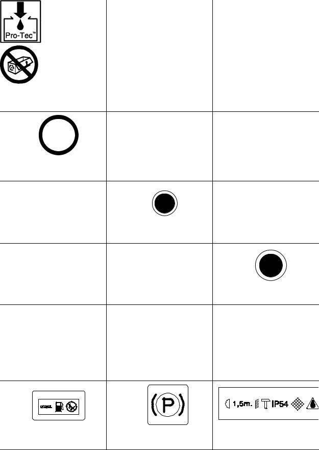
DECALS
Look for these signs on machines manufactured in Europe, which point out potential hazards to the safety of you and others. Read and understand thoroughly. Heed warnings and follow instructions. If you do not understand, inform you supervisor.
GRAPHIC FORM AND MEANING OF ISO SYMBOLS
Prohibition / Mandatory |
|
Information / Instructions |
|
|
|
Warning |
||
|
|
|
|
|
|
|
|
|
WARNING: Electrical shock risk. |
|
WARNING – Pressurised component or |
|
WARNING – Hot surface. |
||||
|
|
|||||||
|
|
system. |
|
|
|
|
|
|
|
|
|
|
|
|
|
|
|
WARNING – Pressure control. |
|
WARNING – Corrosion risk. |
|
WARNING – Air/gas flow or Air |
||||
|
|
|
|
discharge. |
||||
|
|
|
|
|
|
|||
|
|
|
|
|
|
|
|
|
|
|
|
|
|
|
|
|
|
|
|
|
|
|
|
|
|
|
|
|
|
|
|
|
X,XBAR |
|
|
|
|
|
|
|
|
|
|
|
WARNING – Pressurised vessel. |
|
WARNING – Hot and harmful exhaust |
|
WARNING – Maintain correct tyre |
||||
|
|
pressure. (Refer to the GENERAL |
||||||
|
gas. |
|
||||||
|
|
|
INFORMATION section of this manual). |
|||||
|
|
|
|
|||||
|
|
|
|
|
|
|
|
|
9 |
7/120 (P425AWIR), 9/110 (XP375AWIR), 10/105 (HP375AWIR), 14/85 (VHP300AWIR), |
7/170 (P600WIR), 10/125 (HP450WIR), 14/115 (VHP400WIR) |

0_C
|
WARNING – Before connecting the tow |
WARNING – For operating temperature |
WARNING – Flammable liquid. |
bar or commencing to tow consult the |
below 0_C, consult the operation and |
|
operation and maintenance manual. |
maintenance manual. |
WARNING – Do not undertake any |
WARNING – Consult the operation and |
Do not breathe the compressed air from |
|
maintenance on this machine until the |
|||
maintenance manual before |
|||
electrical supply is disconnected and |
this machine. |
||
commencing any maintenance. |
|||
the air pressure is totally relieved. |
|
||
|
|
Do not remove the Operating and
Maintenance manual and manual holder Do not stack.
Do not operate the machine without the
from this machine.
guard being fitted.
7/120 |
(P425AWIR), 9/110 |
(XP375AWIR), 10/105 (HP375AWIR), 14/85 (VHP300AWIR), |
10 |
7/170 |
(P600WIR), 10/125 |
(HP450WIR), 14/115 (VHP400WIR) |
Do not stand on any service valve or other |
Do not operate with the doors or enclosure |
Do not use fork lift truck from this side. |
|
parts of the pressure system. |
open. |
||
|
XX |
|
|
|
km/h |
|
|
|
Do not exceed the trailer speed limit. |
No naked lights. |
Do not open the service valve before the |
|
airhose is attached. |
|||
|
|
|
|
|
|
|
|
|
|
|
|
|
|
|
|
|
|
|
|
|
|
|
|
|
|
|
|
|
Use fork lift truck from this side only. |
Emergency stop. |
Tie down point |
||||||
|
|
|
|
|
|
|
|
|
|
|
|
|
|
|
|
|
|
|
|
|
|
|
|
|
|
|
|
|
|
|
|
|
|
|
|
Lifting point. |
On (power). |
Off (power). |
Read the Operation and Maintenance
When parking use prop stand, handrake
manual before operation or maintenance Compressor oil filling and wheel chocks.
of this machine is undertaken.
Diesel fuel |
Parking brake. |
Rough Service Designation. |
|
No open flame. |
Wet Location Operation. |
||
|
11 |
7/120 (P425AWIR), 9/110 (XP375AWIR), 10/105 (HP375AWIR), 14/85 (VHP300AWIR), |
7/170 (P600WIR), 10/125 (HP450WIR), 14/115 (VHP400WIR) |
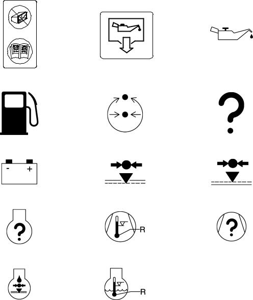
Replace any cracked protective shield. |
Oil drain. |
Engine Oil |
|
|
|
Fuel level/point |
Pressure control |
Malfunction |
|
|
|
Battery charging condition |
Low pressure |
High pressure |
|
|
|
Engine malfunction |
High compressor temperature |
Compressor malfunction |
|
|
|
Low engine oil pressure |
Engine high temperature |
|
|
|
|
7/120 |
(P425AWIR), 9/110 |
(XP375AWIR), 10/105 (HP375AWIR), 14/85 (VHP300AWIR), |
12 |
7/170 |
(P600WIR), 10/125 |
(HP450WIR), 14/115 (VHP400WIR) |

SAFETY
WARNINGS
Warnings call attention to instructions which must be followed precisely to avoid injury or death.
CAUTIONS
Cautions call attention to instructions which must be followed precisely to avoid damaging the product, process or its surroundings.
NOTES
Notes are used for supplementary information.
General Information
Never operate unit without first observing all safety warnings and carefully reading the operation and maintenance manual shipped from the factory with this machine.
Ensure that the operator reads and understands the decals and consults the manuals before maintenance or operation.
Ensure that the Operation and Maintenance manual, and the manual holder, are not removed permanently from the machine.
Ensure that maintenance personnel are adequately trained, competent and have read the Maintenance Manuals.
Make sure that all protective covers are in place and that the canopy/doors are closed during operation.
The specification of this machine is such that the machine is not suitable for use in flammable gas risk areas. If such an application is required then all local regulations, codes of practice and site rules must be observed. To ensure that the machine can operate in a safe and reliable manner, additional equipment such as gas detection, exhaust spark arrestors, and intake (shut–off) valves may be required, dependant on local regulations or the degree of risk involved.
A weekly visual check must be made on all fasteners/fixing screws securing mechanical parts. In particular, safety–related parts such as coupling hitch, drawbar components, road–wheels, and lifting bail should be checked for total security.
All components which are loose, damaged or unserviceable, must be rectified without delay.
Air discharged from this machine may contain carbon monoxide or other contaminants which will cause serious injury or death. Do not breathe this air.
This machine produces loud noise with the doors open or service valve vented. Extended exposure to loud noise can cause hearing loss. Always wear hearing protection when doors are open or service valve is vented.
Never inspect or service unit without first disconnecting battery cable(s) to prevent accidental starting.
Do not use petroleum products (solvents or fuels) under high pressure as this can penetrate the skin and result in serious illness. wear eye protection while cleaning unit with compressed air to prevent debris from injuring eye(s).
Rotating fan blade can cause serious injury. Do not operate without guard in place.
Use care to avoid contacting hot surfaces (engine exhaust manifold and piping, air receiver and air discharge piping, etc.).
Ether is an extremely volatile, highly inflammable gas. When it is specified as a starting aid, use sparingly. DO NOT USE
ETHER IF THE MACHINE HAS GLOW PLUGS OR INLET HEATER STARTING AIDS OR ENGINE DAMAGE WILL RESULT.
Never operate unit with guards, covers or screens removed. Keep hands, hair, clothing, tools, blow gun tips, etc. well away from moving parts.
Compressed air
Compressed air can be dangerous if incorrectly handled. Before doing any work on the unit, ensure that all pressure is vented from the system and that the machine cannot be started accidentally.
Ensure that the machine is operating at the rated pressure and that the rated pressure is known to all relevant personnel.
All air pressure equipment installed in or connected to the machine must have safe working pressure ratings of at least the machine rated pressure.
If more than one compressor is connected to one common downstream plant, effective check valves and isolation valves must be fitted and controlled by work procedures, so that one machine cannot accidently be pressurised / over pressurised by another.
Compressed air must not be used for a direct feed to any form of breathing apparatus or mask.
High Pressure Air can cause serious injury or death. Relieve pressure before removing filler plugs/caps, fittings or covers.
Air pressure can remain trapped in air supply line which can result in serious injury or death. Always carefully vent air supply line at tool or vent valve before performing any service.
The discharged air contains a very small percentage of compressor lubricating oil and care should be taken to ensure that downstream equipment is compatible.
If the discharged air is to be ultimately released into a confined space, adequate ventilation must be provided.
When using compressed air always use appropriate personal protective equipment.
All pressure containing parts, especially flexible hoses and their couplings, must be regularly inspected, be free from defects and be replaced according to the Manual instructions.
Avoid bodily contact with compressed air.
The safety valve located in the separator tank must be checked periodically for correct operation.
13 |
7/120 (P425AWIR), 9/110 (XP375AWIR), 10/105 (HP375AWIR), 14/85 (VHP300AWIR), |
7/170 (P600WIR), 10/125 (HP450WIR), 14/115 (VHP400WIR) |

Whenever the machine is stopped, air will flow back into the compressor system from devices or systems downstream of the machine unless the service valve is closed. Install a check valve at the machine service valve to prevent reverse flow in the event of an unexpected shutdown when the service valve is open.
Disconnected air hoses whip and can cause serious injury or death. Always attach a safety flow restrictor to each hose at the source of supply or branch line in accordance with OSHA
Regulation 29CFR Section 1926.302(b).
Never allow the unit to sit stopped with pressure in the receiver–separator system.
Materials
The following substances may be produced during the operation of this machine:
. brake lining dust
. engine exhaust fumes
AVOID INHALATION
Ensure that adequate ventilation of the cooling system and exhaust gases is maintained at all times.
The following substances are used in the manufacture of this machine and may be hazardous to health if used incorrectly:
. anti–freeze
. compressor lubricant
. engine lubricant
. preservative grease
. rust preventative
. diesel fuel
. battery electrolyte
AVOID INGESTION, SKIN CONTACT AND INHALATION OF FUMES
Should compressor lubricant come into contact with the eyes, then irrigate with water for at least 5 minutes.
Should compressor lubricant come into contact with the skin, then wash off immediately.
Consult a physician if large amounts of compressor lubricant are ingested.
Consult a physician if compressor lubricant is inhaled.
Never give fluids or induce vomiting if the patient is unconscious or having convulsions.
Safety data sheets for compressor and engine lubricants should be obtained from the lubricant supplier.
Never operate the engine of this machine inside a building without adequate ventilation. Avoid breathing exhaust fumes when working on or near the machine.
This machine may include such materials as oil, diesel fuel, antifreeze, brake fluid, oil/air filters and batteries which may require proper disposal when performing maintenance and service tasks. Contact local authorities for proper disposal of these materials.
Battery
A battery contains sulphuric acid and can give off gases which are corrosive and potentially explosive. Avoid contact with skin, eyes and clothing. In case of contact, flush area immediately with water.
DO NOT ATTEMPT TO SLAVE START A FROZEN BATTERY SINCE THIS MAY CAUSE IT TO EXPLODE.
Exercise extreme caution when using booster battery. To jump battery, connect ends of one booster cable to the positive
(+) terminal of each battery. Connect one end of other cable to the negative (–) terminal of the booster battery and other end to a ground connection away from dead battery (to avoid a spark occurring near any explosive gases that may be present). After starting unit, always disconnect cables in reverse order.
Radiator
Hot engine coolant and steam can cause injury. Ensure that the radiator filler cap is removed with due care and attention.
Do not remove the pressure cap from a HOT radiator. Allow radiator to cool down before removing pressure cap.
Transport
When loading or transporting machines ensure that the specified lifting and tie down points are used.
When loading or transporting machines ensure that the towing vehicle, its size, weight, towing hitch and electrical supply are all suitable to provide safe and stable towing at speeds either, up to the legal maximum for the country in which it is being towed or, as specified for the machine model if lower than the legal maximum.
Ensure that the maximum trailer weight does not exceed the maximum gross weight of the machine (by limiting the equipment load), limited by the capacity of the running gear.
Note:
Gross mass (on data plate) is for the basic machine and fuel only, excluding any fitted options, tools, equipment and foreign materials.
Before towing the machine, ensure that:–
. the tyres and towing hitch are in a serviceable condition.
. the canopy is secure.
. all ancillary equipment is stored in a safe and secure manner.
. the brakes and lights are functioning correctly and meet necessary
road traffic requirements.
. break-away cables/safety chains are connected to the towing
vehicle.
The machine must be towed in a level attitude in order to maintain correct handling, braking and lighting functions. This can be achieved by correct selection and adjustment of the vehicle towing hitch and, on variable height running gear, adjustment of the drawbar.
To ensure full braking efficiency, the front (towing eye) section must always be set level.
When adjusting variable height running gear:–
7/120 |
(P425AWIR), 9/110 |
(XP375AWIR), 10/105 (HP375AWIR), 14/85 (VHP300AWIR), |
14 |
7/170 |
(P600WIR), 10/125 |
(HP450WIR), 14/115 (VHP400WIR) |

Ensure front (towing eye) section is set level
When raising towing eye, set rear joint first, then front joint.
When lowering towing eye, set front joint first, then rear joint.
After setting, fully tighten each joint by hand and then tighten further to the next pin. Refit the pin.
When parking always use the handbrake and, if necessary, suitable wheel chocks.
Make sure wheels, tyres and tow bar connectors are in safe operating condition and tow bar is properly connected before towing.
Safety chains / connections and their adjustment
The legal requirements for the joint operation of the breakaway cable and safety chains are as yet unidentified by
71/320/EEC or UK regulations. Consequently we offer the following advice / instructions.
Where brakes only are fitted:
a)Ensure that the breakaway cable is securely coupled to the handbrake lever and also to a substantial point on the towing vehicle.
b)Ensure that the effective cable length is as short as possible, whilst still allowing enough slackness for the trailer to articulate without the handbrake being applied.
Where brakes and safety chains are fitted:
a)Loop the chains onto the towing vehicle using the towing vehicle hitch as an anchorage point, or any other point of similar strength.
b)Ensure that the effective chain length is as short as possible whilst still allowing normal articulation of the trailer and effective operation of the breakaway cable.
Where safety chains only are fitted:
a)Loop the chains onto the towing vehicle using the towing vehicle hitch as an anchorage point, or any other point of similar strength.
b)When adjusting the safety chains there should be sufficient free length in the chains to allow normal articulation, whilst also being short enough to prevent the towbar from touching the ground in the event of an accidental separation of the towing vehicle from the trailer.
15 |
7/120 (P425AWIR), 9/110 (XP375AWIR), 10/105 (HP375AWIR), 14/85 (VHP300AWIR), |
7/170 (P600WIR), 10/125 (HP450WIR), 14/115 (VHP400WIR) |
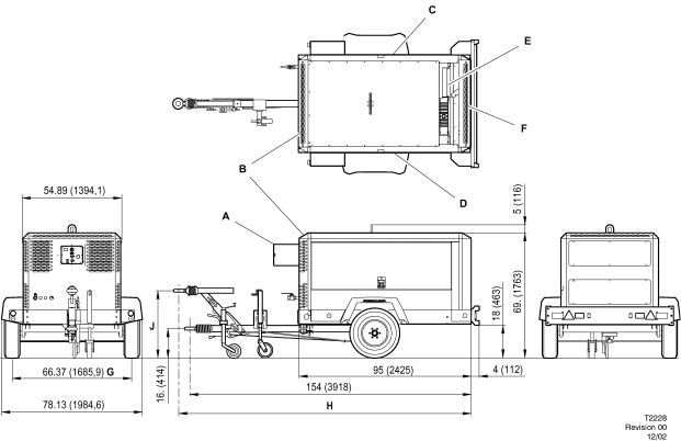
7/120 9/110 10/105 14/85 P425AWIR XP375AWIR HP375AWIR VHP300AWIR
All dimensions in inches(mm)
AInstrument panel access door
BPackage air inlet
CAccess items:
Separator element & fill
Compressor oil filter
Fuel filters
Dipstick
Engine oil fill
Coolant bottle fill
D Access items:
Fuel fill Engine oil filter
Fuel filter
Engine and compressor air filter
MANUFACTURED IN EUROPE
EAccess items: Radiator fill
FPackage air outlet
GTrack width
HVariable height drawbar
162 (4114) minimum / 168 (4277) maximum
JVariable height drawbar
17 (420) minimum / 35 (880) maximum
7/120 |
(P425AWIR), 9/110 |
(XP375AWIR), 10/105 (HP375AWIR), 14/85 (VHP300AWIR), |
16 |
7/170 |
(P600WIR), 10/125 |
(HP450WIR), 14/115 (VHP400WIR) |
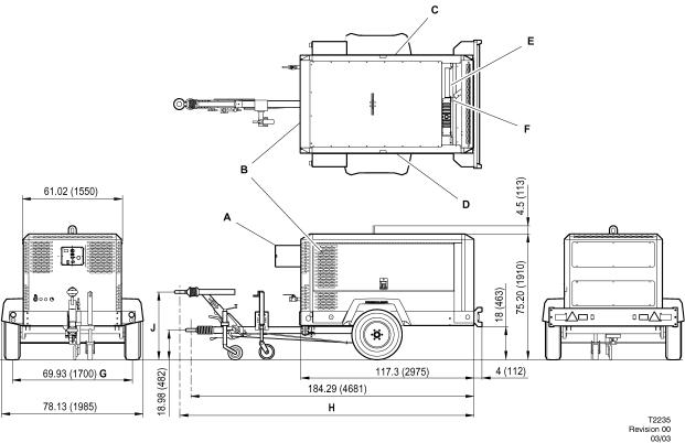
7/170 10/125 14/115
P600WIR HP450WIR VHP400WIR
|
MANUFACTURED IN EUROPE |
All dimensions in inches(mm) |
E Access items: |
A Instrument panel access door |
Radiator fill |
|
|
B Package air inlet |
F Package air outlet |
|
|
C Access items: |
G Track width |
|
|
Separator element & fill |
H Variable height drawbar |
Compressor oil filter |
184.29 (4681) minimum / 189.21 (4806) maximum |
Fuel filters |
J Variable height drawbar |
Dipstick |
|
Engine oil fill |
18.98 (482) minimum / 37.17 (944) maximum |
Coolant bottle fill
D Access items:
Fuel fill
Engine oil filter
Fuel filter
Engine and compressor air filter
17 |
7/120 (P425AWIR), 9/110 (XP375AWIR), 10/105 (HP375AWIR), 14/85 (VHP300AWIR), |
7/170 (P600WIR), 10/125 (HP450WIR), 14/115 (VHP400WIR) |
COMPRESSOR
Actual free air delivery. |
12,0 m3 min–1 (425 CFM) |
|
(7/120) (P425AWIR) |
|
|
Actual free air delivery. |
10,5 m3 min–1 (375 CFM) |
|
(9/110) (XP375AWIR) |
|
|
Actual free air delivery. |
10,5 m3 min–1 (375 CFM) |
|
(10/105) (HP375AWIR) |
|
|
Actual free air delivery. |
8,5 m3 min–1 (300 CFM) |
|
(14/85) (VHP300AWIR) |
|
|
Actual free air delivery. |
17,0 m3 min–1 (600 CFM) |
|
(7/170) (P600WIR) |
|
|
Actual free air delivery. |
12,8 m3 min–1 (450 CFM) |
|
(10/125) (HP450WIR) |
|
|
Actual free air delivery. |
11,3 m3 min–1 (400 CFM) |
|
(14/115) (VHP400WIR) |
|
|
|
|
|
Normal operating discharge pressure. |
7 bar (100 PSI) |
|
(7/120) (P425AWIR) |
|
|
Normal operating discharge pressure. |
8,6 bar (125 PSI) |
|
(9/110) (XP375AWIR) |
|
|
Normal operating discharge pressure. |
10,3 bar (150 PSI) |
|
(10/105) (HP375AWIR) |
|
|
Normal operating discharge pressure. |
14 bar (200 PSI) |
|
(14/85) (VHP300AWIR) |
|
|
Normal operating discharge pressure. |
7 bar (100 PSI) |
|
(7/170) (P600WIR) |
|
|
Normal operating discharge pressure. |
10,3 bar (150 PSI) |
|
(10/125) (HP450WIR) |
|
|
Normal operating discharge pressure. |
14 bar (200 PSI) |
|
(14/115) (VHP400WIR) |
|
|
|
|
|
Maximum allowable pressure. |
|
8,6 bar (125 PSI) |
(7/120) (P425AWIR) |
|
|
Maximum allowable pressure. |
|
10.3 bar (150 PSI) |
(9/110) (XP375AWIR) |
|
|
Maximum allowable pressure. |
|
12.1 bar (175 PSI) |
(10/105) (HP375AWIR) |
|
|
Maximum allowable pressure. |
|
15.5 bar (225 PSI) |
(14/85) (VHP300AWIR) |
|
|
Maximum allowable pressure. |
|
8,6 bar (125 PSI) |
(7/170) (P600WIR) |
|
|
Maximum allowable pressure. |
|
12.1 bar (175 PSI) |
(10/125) (HP450WIR) |
|
|
Maximum allowable pressure. |
|
15.5 bar (225 PSI) |
(14/115) (VHP400WIR) |
|
|
|
|
|
Safety valve setting. |
|
10 bar (150 PSI) |
|
(7/120) (P425AWIR) |
|
|
|
Safety valve setting. |
|
10 |
bar (200 PSI) |
(9/110) (XP375AWIR) |
|
|
|
Safety valve setting. |
|
14 |
bar (200 PSI) |
(10/105) (HP375AWIR) |
|
|
|
Safety valve setting. |
|
17 bar ( 250 PSI) |
|
(14/85) (VHP300AWIR) |
|
|
|
Safety valve setting. |
|
10 bar (150 PSI) |
|
(7/170) (P600WIR) |
|
|
|
Safety valve setting. |
|
14 |
bar (200 PSI) |
(10/125) (HP450WIR) |
|
|
|
Safety valve setting. |
|
17 bar ( 250 PSI) |
|
(14/115) (VHP400WIR) |
|
|
|
|
|
||
Maximum pressure ratio (absolute). |
7 ,9 : 1 |
||
(7/120) (P425AWIR) |
|
|
|
Maximum pressure ratio (absolute). |
9, 6 : 1 |
||
(9/110) (XP375AWIR) |
|
|
|
Maximum pressure ratio (absolute). |
11, 3 : 1 |
||
(10/105) (HP375AWIR) |
|
|
|
Maximum pressure ratio (absolute). |
14, 8 : 1 |
||
(14/85) (VHP300AWIR) |
|
|
|
Maximum pressure ratio (absolute). |
7 ,9 : 1 |
||
(7/170) (P600WIR) |
|
|
|
Maximum pressure ratio (absolute). |
11, 3 : 1 |
||
(10/125) (HP450WIR) |
|
|
|
Maximum pressure ratio (absolute). |
14, 8 : 1 |
||
(14/115) (VHP400WIR) |
|
|
|
|
|
|
|
Operating ambient temperature. |
|
|
|
Whisperized |
–12_C TO +49_C (1O_F TO 120_F) |
||
Maximum discharge temperature. |
120_C (248_F) |
||
Cooling system. |
|
Oil injection |
|
Oil capacity. |
|
36 litres ( 9.5 GAL) |
|
Maximum oil system temperature. |
120_C (248_F) |
||
|
|
||
Maximum oil system pressure. |
8,6 bar (125 PSI) |
||
(7/120) (P425AWIR) |
|
|
|
Maximum oil system pressure. |
10.3 bar (150 PSI) |
||
(9/110) (XP375AWIR) |
|
|
|
Maximum oil system pressure. |
12.1 bar (175 PSI) |
||
(10/105) (HP375AWIR) |
|
|
|
Maximum oil system pressure. |
15.5 bar (225 PSI) |
||
(14/85) (VHP300AWIR) |
|
|
|
Maximum oil system pressure. |
8,6 bar (125 PSI) |
||
(7/170) (P600WIR) |
|
|
|
Maximum oil system pressure. |
12.1 bar (175 PSI) |
||
(10/125) (HP450WIR) |
|
|
|
Maximum oil system pressure. |
15.5 bar (225 PSI) |
||
(14/115) (VHP400WIR) |
|
|
|
|
|
|
|
LUBRICATING OIL SPECIFICATION
(for the specified ambient temperatures).
ABOVE –23_C(–9_F)
Recommended: Pro–Tect
Approved: SAE 10W, API CF–4/CG–4
7/120 |
(P425AWIR), 9/110 |
(XP375AWIR), 10/105 (HP375AWIR), 14/85 (VHP300AWIR), |
18 |
7/170 |
(P600WIR), 10/125 |
(HP450WIR), 14/115 (VHP400WIR) |

BELOW –23_C(–9_F)
Mandatory: IR Performance 500
Ingersoll–Rand Pro–TecTM compressor fluid is factory–fitted, for use at all ambient temperatures above –23_C(–9_F).
NOTE: Warranty may be extended only by continuous use of Pro–Tect and Ingersoll–Rand oil filters and separators.
No other oil/fluids are compatible with Pro–TecTM
No other oils/fluids should be mixed with Pro–TecTM because the resulting mixture could cause damage to the airend.
In the event that Pro–TecTM is not available and / or the end user needs to use an approved single grade engine oil, the complete system including separator / receiver, cooler and pipework must be flushed clear of the first fill fluid and new Ingersoll–Rand oil filters installed.
When this has been completed, the following oils are approved:
a)for ambient temperatures above –23_C(–9_F), SAE 10W, API CF–4/CG–4
b)for ambient temperatures below –23_C(–9_F),
I–R Performance 500 only.
Safety data sheets can be obtained on request from the lubricant supplier.
For temperatures outside the specified ambient range, consult Ingersoll–Rand.
ENGINE |
|
|
|
|
7/120 (P425WIR), |
9/110 (XP375AWIR), |
|
||
10/105 (HP375AWIR), |
14/85 (VHP300AWIR) |
|
||
|
|
|
|
|
Type/model. |
|
|
Ingersoll–Rand |
|
Number of cylinders. |
|
|
4 |
|
Oil capacity. |
|
|
13.2 litres ( 3.5 GAL) |
|
Speed at full load. |
|
|
2400 |
revs |
min–1(RPM) |
|
|
|
|
Speed at idle. |
|
|
1400 revs |
min–1 |
(RPM) |
|
|
|
|
Electrical system. |
|
|
24V negative earth |
|
Power available at 2400 revs min–1 |
93 kW (125 HP) |
|||
Fuel tank capacity |
|
|
219.5 litres |
( 58 |
GAL) |
|
|
|
|
Oil specification |
|
|
Refer engine section |
|
Coolant capacity |
|
|
17 litres(4.5 GAL) |
|
ENGINE
7/170 (P600WIR), 10/125 (HP450WIR), 14/115 (VHP400WIR)
Type/model. |
Ingersoll–Rand |
Number of cylinders. |
6 |
Oil capacity. |
22.1 litres (5.75 GAL) |
Speed at full load. |
2400 revs min–1 |
|
(RPM) |
Speed at idle. |
1400 revs min–1 |
|
(RPM) |
Electrical system. |
24V negative earth |
Power available at 2400 revs min–1 |
126.8 kW (170 HP) |
Fuel tank capacity |
276 litres |
|
(73 GAL) |
Oil specification |
Refer engine section |
Coolant capacity |
28.4 litres(7.5 GAL) |
SOUND LEVEL DATA (‘W’ model)
A) To Pneurop code PN8NTC2.
Equivalent continuous sound pressure level.*
. Rated load |
85 dB(A) |
(Operator position :–1m from machine) |
|
Sound power level (84/533/EEC) |
101 dB(A) |
B) In compliance with 86/188/EEC. |
|
Average sound pressure level at 10m |
|
to 79/113/EEC.* |
73 dB(A) |
(*Machine only :– at maximum load in open site conditions)
C) EPA Noise 76 dB(A)
FIXED HEIGHT RUNNING GEAR (European Only) Braked version
(7/120) ( 9/110), (10/105), (14/85)
Shipping weight. |
1935kg (4266Lbs) |
Maximum weight. |
2200kg (4850Lbs) |
Maximum horizontal towing force. |
2009kg (4429Lbs) |
Maximum vertical coupling load |
|
(nose weight). |
100 kgf (220 Lbs) |
FIXED HEIGHT RUNNING GEAR (European Only) Braked version
(7/170), (10/125), (14/115)
Shipping weight. |
2364kg (5200Lbs) |
Maximum weight. |
2598kg (5715Lbs) |
Maximum horizontal towing force. |
2700kg (5940Lbs) |
Maximum vertical coupling load |
|
(nose weight). |
150 kgf (330 Lbs) |
19 |
7/120 (P425AWIR), 9/110 (XP375AWIR), 10/105 (HP375AWIR), 14/85 (VHP300AWIR), |
7/170 (P600WIR), 10/125 (HP450WIR), 14/115 (VHP400WIR) |

VARIABLE HEIGHT RUNNING GEAR (European Only) Braked version
(7/120) ( 9/110), (10/105), (14/85)
Shipping weight. |
1965kg (4331Lbs) |
Maximum weight. |
2200kg (4850Lbs) |
Maximum horizontal towing force. |
2009kg (4429Lbs) |
Maximum vertical coupling load |
|
(nose weight). |
100 kgf (220 Lbs) |
VARIABLE HEIGHT RUNNING GEAR (European Only) Braked version
(7/170), (10/125), (14/115)
Shipping weight. |
2400kg (5280Lbs) |
Maximum weight. |
2636kg (5800Lbs) |
Maximum horizontal towing force. |
2900kg (5940Lbs) |
Maximum vertical coupling load |
|
(nose weight). |
150 kgf (330 Lbs) |
WHEELS AND TYRES (European) – 7/120, 9/110, 10/105, 14/85
Number of wheels. |
2 x 5.5 |
Tyre size. |
205/75 R16 |
Tyre pressure. |
4.5 bar (65 psi) |
WHEELS AND TYRES (European) – 7/170, 10/125, 14/115 |
|
|
|
Number of wheels. |
2 x 6.0 |
Tyre size. |
205/75 P17.5 |
Tyre pressure. |
6.5 bar (94 psi) |
Further information may be obtained by request through Ingersoll–Rand customer services department.
COMMISSIONING
Upon receipt of the unit, and prior to putting it into service, it is important to adhere strictly to the instructions given below in
PRIOR TO STARTING.
Ensure that the operator reads and understands the decals and consults the manuals before maintenance or operation.
Ensure that the position of the emergency stop device is known and recognised by its markings. Ensure that it is functioning correctly and that the method of operation is known.
Running gear drawbar (European Area) – Machines are shipped to some areas with the drawbar removed. Fitting involves four nuts / bolts to secure the drawbar to the axle and two bolts to fit the drawbar to the front of the machine with the
saddle and spacer block.
Support the front of the machine, fit the wheel chocks to stop the machine moving and attach the drawbar. Refer to the torque value table in the MAINTENANCE section of this manual for the correct torque values.
CAUTION:
This is a safety critical procedure. Double check the torque settings after assembly
Fit the propstand and coupling. Remove the supports and set the machine level.
Before towing the unit, ensure that the tyre pressures are correct (refer to the GENERAL INFORMATION section of this manual) and that the handbrake is functioning correctly (refer to the MAINTENANCE section of this manual). Before towing the unit during the hours of darkness, ensure that the lights are functioning correctly (where fitted).
Ensure that all transport and packing materials are discarded.
Ensure that the correct fork lift truck slots or marked lifting / tie down points are used whenever the machine is lifted or transported.
When selecting the working position of the machine ensure that there is sufficient clearance for ventilation and exhaust requirements, observing any specified minimum dimensions (to walls, floors etc.).
Adequate clearance needs to be allowed around and above the machine to permit safe access for specified maintenance tasks.
Ensure that the machine is positioned securely and on a stable foundation. Any risk of movement should be removed by suitable means, especially to avoid strain on any rigid discharge piping.
Attach the battery cables to the battery(s) ensuring that they are tightened securely. Attach the negative cable before attaching the positive cable.
WARNING: All air pressure equipment installed in or connected to the machine must have safe working pressure ratings of at least the machine rated pressure, and materials compatible with the compressor lubricant
(refer to the GENERAL INFORMATION section).
WARNING: If more than one compressor is connected to one common downstream plant, effective check valves and isolation valves must be fitted and controlled by work procedures, so that one machine cannot accidently be pressurised / over pressurised by another.
WARNING: If flexible discharge hoses are to carry more than 7 bar pressure then it is recommended that safety retaining wires are used on the hoses.
7/120 |
(P425AWIR), 9/110 |
(XP375AWIR), 10/105 (HP375AWIR), 14/85 (VHP300AWIR), |
20 |
7/170 |
(P600WIR), 10/125 |
(HP450WIR), 14/115 (VHP400WIR) |
 Loading...