


Ingersoll Rand
System Automation
X8I & X12I
Quick Setup Guide
Before installing or starting this unit for the first time, this manual should be studied carefully to obtain a working knowledge of the unit and or the duties to be performed while operating and maintaining the unit.
RETAIN THIS MANUAL WITH UNIT. This Technical manual contains IMPORTANT SAFETY DATA and should be kept with the unit at all times.
More Than Air. Answers.
Online answers: http://www.air.irco.com
C.C.N. : 80445067 REV. : A
DATE : DECEMBER 2008

SECTION 1 — TABLE OF CONTENTS
SECTION 1 — TABLE OF CONTENTS ..................................... |
1 |
SECTION 2 — INTRODUCTION............................................. |
2 |
SECTION 3 — SAFETY.......................................................... |
2 |
INSTALLATION........................................................................... |
2 |
OPERATION.............................................................................. |
2 |
MAINTENANCE AND REPAIR........................................................ |
2 |
SECTION 4 — SYSTEM OVERVIEW ....................................... |
4 |
SECTION 5 — INSTALLATION OVERVIEW ............................. |
5 |
SECTION 6 — BEFORE YOU START....................................... |
6 |
CHECK LIST .............................................................................. |
6 |
CHECK LIST GUIDANCE ............................................................... |
6 |
ASSISTANCE.............................................................................. |
7 |
INTELLISYS CONTROLLER E PROM REFERENCE LIST........................... |
7 |
SECTION 7 — MENU NAVIGATION ...................................... |
8 |
X8I USER INTERFACE ................................................................. |
8 |
X8I INFORMATION DISPLAYS ..................................................... |
11 |
X12I USER INTERFACE ............................................................. |
12 |
USER MENU........................................................................... |
14 |
X12I INFORMATION DISPLAYS ................................................... |
15 |
X8I AND X12I INDICATORS ....................................................... |
18 |
COMPRESSOR IDENTIFICATION ................................................... |
19 |
X8I & X12I CONTROL KEYPAD FUNCTIONS .................................. |
19 |
SECTION 8 — QUICK SETUP COMMISSIONING................... |
21 |
PHYSICAL CHECKS.................................................................... |
21 |
PRESSURE DISPLAY .................................................................. |
21 |
QUICK SET UP CONFIGURATION ................................................ |
21 |
OPTIONAL FEATURES AND FUNCTIONS ........................................ |
21 |
SECTION 9 — SYSTEM CONFIGURATION............................ |
22 |
X8I OR X12I CONFIGURATION SCREENS ...................................... |
22 |
X8I OR X12I COMPRESSOR CONNECTIVITY AND FUNCTIONAL SETTINGS |
|
............................................................................................ |
25 |
SECTION 10 WIRING DIAGRAMS........................................ |
28 |
X8I, EXP, EX, VSD MA, VSD V, I/O, CX, DX, SMG POWER SUPPLY |
|
CONNECTION ......................................................................... |
28 |
X12I POWER SUPPLY CONNECTION............................................ |
28 |
X8I, X12I PRESSURE TRANSDUCER CONNECTION.......................... |
28 |
X8I, X12I RS485 CONNECTION ................................................ |
29 |
EX BOX RS485 CONNECTION ................................................... |
29 |
VSD MA, VSD V BOX RS485 CONNECTION................................ |
29 |
I/O BOX RS485 CONNECTION .................................................. |
29 |
CX BOX RS485 CONNECTION ................................................... |
29 |
DX BOX RS485 CONNECTION................................................... |
29 |
X8I TO EXP RS485 CONNECTION.............................................. |
29 |
X12I TO EXP RS485 CONNECTION............................................ |
29 |
IR485, IRV485 GATEWAY CONNECTION ..................................... |
30 |
IR 485 GATEWAY SWITCH SETTINGS .......................................... |
31 |
IRV 485 GATEWAY SWITCH SETTINGS ........................................ |
32 |
IRPCB CONNECTION................................................................ |
33 |
SMG BOX RS485 CONNECTION................................................ |
33 |
VX BOX CONNECTION.............................................................. |
34 |
 Refer to Section Indicated
Note
Important or Caution, Safety
1

SECTION 2 — INTRODUCTION
This manual is intended as a quick reference to establish basic sequence control of the compressors with the X8I or X12I. This document details the minimum required hardware setup process for the product. Please refer to the Operator’s Manual for complete setup and operating
instructions. If you have any questions regarding the X8I or X12I, please contact your local authorized and trained Ingersoll Rand Service Center or contact Technical Support Services at 800-820-0308 to speak one of our Technical Support Engineers.
SECTION 3 — SAFETY
!WARNING : Risk of Danger
WARNING : Risk of Electric Shock
OPERATION
•The X8I or X12I must only be operated by competent personnel under qualified supervision.
! |
WARNING : Risk of High Pressure |
|
WARNING : Consult Manual
•Before installing or operating the X8I or X12I, take time to carefully read all the instructions contained in this manual, all compressor manuals, and all manuals of any other peripheral devices that may be installed or connected to the product.
•Electricity and compressed air have the potential to cause severe personal injury or property damage.
•The operator should use common sense and good working practices while operating and maintaining this system. All applicable codes should be strictly adhered to.
•Maintenance must be performed by adequately qualified personnel that are equipped with the proper tools.
INSTALLATION
•Installation work must only be carried out by a competent person under qualified supervision.
•A fused isolation switch must be fitted between the main power supply and the X8I or X12I.
•The X8I or X12I should be mounted in such a location as to allow operational and maintenance access without obstruction or hazard and to allow clear visibility of indicators at all times.
•If raised platforms are required to provide access to the X8I or X12I they must not interfere with normal operation or obstruct access. Platforms and stairs should be of grid or plate construction with safety rails on all open sides.
•Never remove or tamper with safety devices, guards or insulation materials fitted to the X8I or X12I.
•The X8I or X12I must only be operated at the supply voltage and frequency for which it is designed.
•When main power is switched on, lethal voltages are present in the electrical circuits and extreme caution must be exercised whenever it is necessary to carry out any work on the unit.
•Do not open access panels or touch electrical components while voltage is applied unless it is necessary for measurements, tests or adjustments. Such work should be carried out only by a qualified electrician equipped with the correct tools and wearing appropriate protection against electrical hazards.
•All air compressors and/or other equipment connected to the unit should have a warning sign attached stating ‘THIS UNIT MAY START WITHOUT WARNING' next to the display panel.
•If an air compressor and/or other equipment connected to the unit is to be started remotely, attach warning signs to the equipment stating ‘THIS UNIT CAN BE STARTED REMOTELY’ in a prominent location, one on the outside of the equipment, the other inside the equipment control compartment.
MAINTENANCE AND REPAIR
•Maintenance, repairs or modifications must only be carried out by competent personnel under qualified supervision.
•If replacement parts are required use only genuine parts from the original equipment manufacturer, or an alternative approved source.
•Carry out the following operations before opening or removing any access panels or carrying out any work on the X8I or X12I:
•Isolate the X8I or X12I from the main electrical power supply. Lock the isolator in the 'OFF' position and remove the fuses.
2
•Attach a label to the isolator switch and to the unit stating ‘WORK IN PROGRESS - DO NOT APPLY VOLTAGE'. Do not switch on electrical power or attempt to start the X8I or X12I if such a warning label is attached.
•Make sure that all instructions concerning operation and maintenance are strictly followed and that the complete unit, with all accessories and safety devices, is kept in good working order.
•The accuracy of sensor devices must be checked on a regular basis. They must be calibrated when acceptable tolerances are exceeded. Always ensure any pressure within the compressed air system is safely vented to atmosphere before attempting to remove or install a sensor device.
•The X8I or X12I must only be cleaned with a damp cloth, using mild detergents if necessary. Avoid the use of any substances containing corrosive acids or alkalis.
•Do not paint the control faceplate or obscure any indicators, controls, instructions or warnings.
3

SECTION 4 — SYSTEM OVERVIEW
Refer to the X8I or X12I Operator’s Manual and the Interconnect and Application Guide for installation details.
4

SECTION 5 — INSTALLATION OVERVIEW
Refer to the X8I or X12I Operator’s Manual and the Interconnect and Application Guide for installation details.
5

SECTION 6 — BEFORE YOU START
CHECK LIST
Prior to attempting installation and commissioning of the X8I or X12I please review the following check list:
oQuick Set Up Manual is available and has been reviewed
oApplication Guide is available and the correct diagrams have been identified
oIf the specific diagrams are not in the Application Guide the specific compressor control wiring schematic will be required to define the correct interconnection
oOperator’s Manual is available and has been reviewed
oCompressors to be connected can accept remote load / unload commands
oCompressors to be connected have automatic Start / Stop capability
oCorrect compressor controller EPROM is installed or available to allow Remote Control and Auto Start/Stop (SE Controller) See Reference Table Below.
oThe correct wire is available to connect the X8I or X12I with the Compressor / ir-PCB interface
oThe correct wire is available to connect the X8I or X12I with the Compressor / ir-485 and/or irV485 Gateway.
oThe correct wire is available to connect the X8I or X12I with the Optional Integration boxes
oThe correct wire is available to connect the X8I or X12I with the pressure sensor/transducer
oThe X8I or X12I can be located within 330ft (100m) of each compressor using the ir-PCB.
oThe EXP must be located within 33ft (100m) of X8I or X12I
oThe EXP can be located within 330ft (100m) of each compressor using the ir-PCB.
oThe X8I or X12I can be located within 4000ft (1219m) of each compressor using the ir-485 and/or irV-485 Gateway or Optional Integration boxes. (The exception to this is connecting the Optional EXP box to the X8I or X12I. The maximum distance is 33ft (10m) in length.)
oThe Pressure sensor/transducer can be located appropriately within 330ft (100m) for the X8I or X12I Controller
CHECK LIST GUIDANCE
oElectrical Drawing For Each Compressor: It is important to have the Electrical drawing for each compressor so that the correct interconnect drawing can be referenced from the Interconnect and Application Guide
oTypes of Compressors To Be Sequenced: Refer to the Interconnect and Application Guide for specific details on the types of compressors that can be sequenced and their individual requirements such as Auto Restart, Intellisys Software, etc.
oir-PCB and ir-485 and/or irV-485 Gateway Mounting: The ir-PCB and the Gateway module is designed to be installed within the compressor starter enclosure. The mounting location of the ir-PCB should be away from any high voltage connections, contactors, or transformers.
oir-PCB, ir-485 and/or irV-485 Gateway and Compressor Interconnections: Refer to the Interconnect and Application Guide for specific drawings for various compressors and the X8I or X12I. If there is not a specific drawing available for the compressor being sequenced at the site, please contact Technical Support Services for assistance.
oir-PCB, ir-485 and/or irV-485 Gateway and Compressor Interconnection Wire: The X8I or X12I Installation kit contains 330 Ft (100m) of 18 gauge stranded wire (Orange) to use for the connections between the ir-PCB and the compressor. In most cases, this is sufficient for most installations. If additional wire is required, any 18 gauge stranded wire can be used in lieu of the wire provided in the kit.
X8I or X12I Installation kit also contains an interconnect cable for the connection between the ir-485 Gateway and the Intellisys Controller.
oX8I or X12I, EXP, EX and ir-PCB Interconnect Wire: The cable used between the X8I or X12I and the compressor ir-PCB interconnection is designed to use 7-conductor shielded cable or individual wires run through earthed/grounded metal conduit/tubing. (18 gauge wire).
oThe cable used between the X8I or X12I, EXP, ir485 and/or irV-485 Gateway or any Optional Integration Boxes is Belden 9841 (or equivalent). It should be run in grounded conduit and should not be greater than 4000 feet (1219 meters) in length (The exception to this is connecting the Optional EXP box to the X8I or X12I. The maximum distance is 33ft (10m) in length.)
6

oX8I or X12I and Pressure Transducer Wire: The X8I or X12I and the pressure transducer interconnection is designed to use 2-conductor shielded cable. (18gauge)
oAll external wiring to the X8I or X12I should be made through the holes (grommets are provided) in the X8I or X12I enclosure (8 in total). Drilling or tapping additional holes in the enclosure can result metal shavings making contact with the circuit boards. Damage due to metal shavings in the circuit boards is not covered by warranty.
oPower / Local Disconnect (Breaker): Incoming power (115VAC/230VAC, single phase) should be fused (100VA) and a local disconnect provided. The power source should be regulated and noise free. The use of a power supply regulator might be required in applications where unregulated power is an issue
ASSISTANCE
oContacting Technical Support Services or Service Bulletins listed on the IR ServiceNet can provide further assistance if there are other questions or concerns prior to Installation and Start-up.
oConfirm that all electrical connections are made properly and tightened and conform to local standards.
oCommon Receiver: The X8I or X12I must have its pressure transducer located in a common receiver for proper Wet Side or Dry Side System pressure control.
Pressure Transducer Installation: The pressure transducer threads are BPT G1/4” DIN3852, Form E, Inox 1, 4305 stainless. It is the equivalent of ¼” NPT.
INTELLISYS CONTROLLER E-PROM REFERENCE LIST
Minimum Recommended E-prom Levels - IntelliSys Controllers
IntelliSys - First Generation |
"Redeye" |
|
|
|
|
|
SSR 50 - 450HP |
1 & 2 stg |
2.4 |
|
|
|
|
Sierra 100 - 200HP |
|
2.7 |
|
|
|
|
Recip |
|
1.62 |
|
|
|
|
|
|
|
|
|
||
IntelliSys - Second Generation |
"SG" |
|
IntelliSys - Second Edition |
"SE" |
||
SSR 50 - 450 |
1 & 2 stg |
1.5 |
|
SSR 15 - 100HP |
|
1.75 |
SSR 75 - 350kW |
ESA |
1.5 |
|
SSR - UP (Pegasus) |
|
1.23 |
Sierra 125-400HP |
|
1.35 |
|
SSR 22 - 150kW |
ESA |
1.93 |
Recip |
|
1.28 |
|
Sierra 50 - 100HP |
|
1.3 |
|
|
|
|
|
|
|
IntelliSys - Nirvana |
|
"SGN" |
|
|
|
|
Nirvana CC 100 - 200HP |
|
1.45 |
|
|
|
|
IntelliSys - Nirvana |
|
"SGNe" |
|
|
|
|
Nirvana CC 50 - 300HP |
|
2.4 |
|
|
|
|
Nirvana OF 50 - 200HP |
|
1.2 |
|
|
|
|
|
|
|
|
|
|
|
7
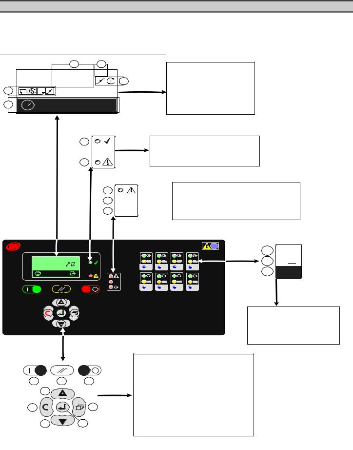
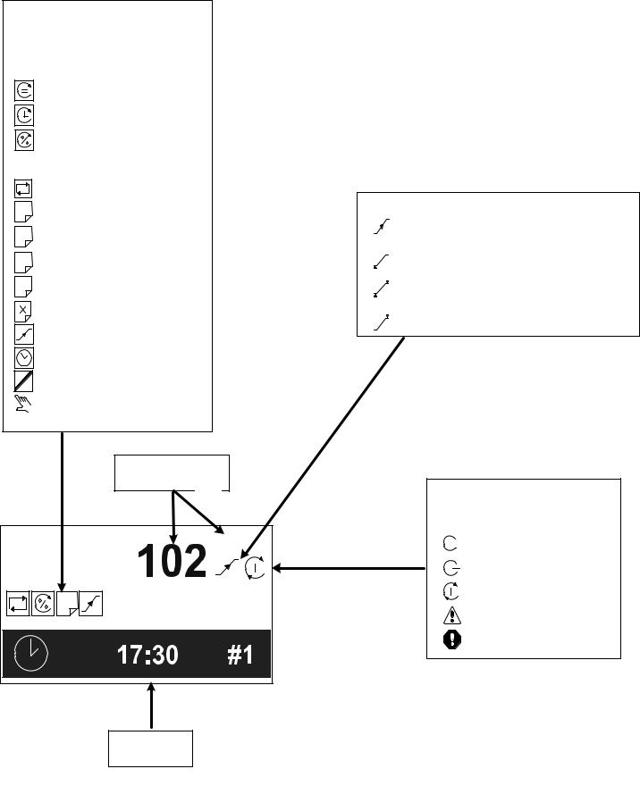
SECTION 7 — MENU NAVIGATION
The Main Display and the keypad and navigation buttons on the X8I or X12I are depicted below and provide the following functionality:
X8I User Interface
|
|
a |
b |
|
|
102 |
PSI |
|
|
c |
|
d |
1 |
|
|
e |
|
17:30 |
#1 |
|
|
a
b CAP
CAP 
c


Ingersoll Rand
102 psi |
1 |
2 |
3 |
4 |
1 A: 85% |
|
|
|
|
|
CAP |
|
|
|
|
5 |
6 |
7 |
8 |
a |
b |
c |
|
g |
|
f |
|
d |
|
h |
e |
a


b


c 1
1
8
1 |
2
3
4
9
17:30 #1
1 A: 100%
#
102 psi
00:00 #1
10
 Loading...