


ENGLISH


 1
1 


PRESENTATION
Welcome to the Husqvarna motorcycling Family!
Your new Husqvarna motorcycle is designed and manufactured to be the finest in its field.
The instructions in this book have been prepared to provide a simple and understandable guide for your motorcycle’s operation and care.
Follow the instructions carefully to obtain maximum performance and your personal motorcycling pleasure. Your owner’s manual contains instructions for owner care and maintenance. Information covering repair of major units such as engine, transmission, etc. is provided in the Husqvarna Service Manual. The information concerning details or main work of repair or maintenance are described in the Husqvarna Service Manual. This manual is available upon request by stating the code number set on pages 95, 96, 97, 98. Work of this kind requires the attention of a skilled mechanic and the use of special tools and equipment.
Your Husqvarna dealer has the facilities, experience and original parts necessary to properly render this valuable service.
This “Owner’s Manual” and the “Purchase Registration Booklet” are parts and parcels of the motorcycle, hence, they have to remain with the motorcycle even when sold to another user.This “Owner’s Manual” and the “Purchase Registration Booklet” are parts and parcels of the motorcycle, hence, they have to remain with the motorcycle even when sold to another user.
This motorcycle uses components designed thanks to systems and state of the art technologies which are thereafter tested in competition.
In competition motorcycles, every detail is verified after each race in order to always guarantee better performance. For correct functioning of the vehicle, it is necessary to follow the maintenance and control table found on Appendix A.
IMPORTANTAppendix . NOTICES TC-TXC
1) The TC and TXC models are guaranteed COMPETITION motorcycles exempt from functional defects, the suggested maintenance table for competition use is shown on
2) TE and SMR are STREET LEGAL |
|
|
|
|
|
TE |
|
||
motorcycles (with LIMITED POWER EN- |
|
|
||
GINE); they are guaranteed exempt |
|
|
|
|
|
|
|
|
|
from functional defects and covered |
|
|
|
|
with legal guarantee, if the STAN- |
|
|
|
|
DARD CONFIGURATION is maintained |
|
|
|
|
and the suggested maintenance table, |
|
|
|
|
shown on Appendix A (page A8) is ob- |
|
|
|
|
served. |
|
|
|
|
If TE and SMR are transformed in |
|
|
|
|
COMPETITION MOTORCYCLES (with |
|
|
|
|
FULL POWER ENGINE), the suggested |
|
|
|
|
maintenance table for competition use |
|
|
|
|
is shown on Appendix A. |
|
SMR |
|
|
|
|
|
|
|
|
|
|
|
|
MOTOCROSS
ENDURO
SUPERMOTARD


 2
2


IMPORTANT
The reference for recognition of the guarantee will be the MOTORCYCLE CONFIGURATION, as shown below:
A)STANDARD MOTORCYCLE, STREET LEGAL: with LIMITED POWER ENGINE
B)COMPETITION MOTORCYCLE, RACING USE: with FULL POWER ENGINE
This motorcycles was not designed for long trips with the engine always at maximum rpm as can occur whilst travelling on roads or highways. Long trips at full throttle can cause severe damage to the engine.
This motorcycles is setup for competition use and therefore guarantees maximum performance with the rider alone. It is thereby not recommended to use the vehicle on circuits or off-road with a passenger.
ALWAYS keep in mind that these motorcycles have been designed strictly for competition use, that is, for conditions of usage very different from those presented on the road.
ALWAYS keep in mind that these motorcycles have been designed strictly for competition use, that is, for conditions of usage very different from those presented on the road.
In order to maintain the vehicle’s “Guarantee of Functionality”, the client must follow the maintenance program indicated in the user’s manual by carrying out maintenance checks at authorized HUSQVARNA dealers. The cost for substitut-
ing parts and for the labour necessary in order to respect the maintenance plan, is charged to the client.
NOTE: the guarantee is EXTINGUISHED in the case where the motorcycle is rented.
Important Notice
Read this manual carefully and pay special attention to statements preceeded by the following words:
Warning*: Indicates a possibility of severe personal injury or loss of life if instructions are not followed.
Caution*: Indicates a possibility of personal injury or equipment damage if instructions are not followed.
Note*: Gives helpful information.
Parts Replacement
When parts replacement is required, use only Husqvarna ORIGINAL parts.
.
Warning*: After an upset, inspect the motorcycle carefully. Make sure that the throttle, brake, clutch and all other systems are undamaged. Riding with a damaged motorcycle can lead to a serious crash.
Warning*: Never attempt to start or operate your motorcycle unless you are wearing appropriate protective clothing. Always wear a motorcycle helmet, motorcycle boots, gloves, goggles and other appropriate protective clothing.
Warning*: This motorcycle is a state of the art competition bike. Do not attempt to start or ride this motorcycle until you have received expert instruction and are in excellent physical condition.
PRECAUTIONS FOR CHILDREN WARNING
●Park the vehicle where it is unlikely to be bumped into or damaged. Even slight or involuntary bumps can cause the vehicle to topple over, with subsequent risk of serious harm to people or children.
●To prevent the vehicle from tipping over, never park it on soft or uneven ground, nor on asphalt strongly heated by the sun.
●Engine and exhaust pipes become very hot during riding. Always park your motorcycle where people or children can not easily reach these parts, in order to avoid serious burns.
EN


 3
3


TABLE OF CONTENTS |
Page |
PRESENTATION........................................................................ |
2 |
IMPORTANT NOTICES............................................................... |
2 |
IDENTIFICATION DATA ............................................................. |
5 |
TECHNICAL DATA ................................................................... |
10 |
LUBRICATION TABLE, SUPPLIES .............................................. |
12 |
CONTROLS ............................................................................ |
13 |
RIDING................................................................................. |
23 |
SERVICE LIMITS..................................................................... |
70 |
IGNITION SYSTEM/ELETTRICAL SYSTEM............................. |
79-90 |
SPECIAL TOOLS ..................................................................... |
91 |
TIGHTENING TORQUES .......................................................... |
92 |
KITS..................................................................................... |
94 |
OPTIONAL PARTS LIST ...................................................... |
95-98 |
APPENDIX............................................................................. |
99 |
PRE-DELIVERY INSPECTION................................................... |
101 |
NOTE FOR USA/CDNAUS MODELS........................................ |
102-104 |
ALPHABETICAL INDEX ......................................................... |
105 |
PERIODIC MAINTENANCE -ADJUSTMENT..................... |
Appendix A |
Note
●References to the “left” or “right” of the motorcycle are in the sense of a person facing forwards.
●Z: number of teeth
●A: Austria AUS: Australia
B:Belgium
BR: Brazil
CDN: Canada
CH: Switzerland
D:Germany
E:Spain
F:France
FIN: |
Finland |
GB: |
Great Britain |
I:Italy
J:Japan
USA: |
United States of America |
●Where not specified, all the data and the instructions are referred to any and all Countries.


 4
4


IDENTIFICATION DATA
The engine number is printed on the upper side of the engine case, whereas the frame number is printed on the steering tube .
Always state the number stamped on the frame (and write it on this booklet), when placing orders for spare parts, or when asking for information on your motorcycle.
FRAME NUMBER
VEHICLE IDENTIFICATION NUMBER (V.I.N.)
The full 17 digit serial, or Vehicle Identification Number, is stamped on the steering head tube (R.H. side).
(*): Progressiv nr. (l): Year of the model
EN
1.Frame serial number
2.Engine serial number


 5
5


VEHICLE IDENTIFICATION NUMBER (V.I.N.)
The full 17 digit serial, or Vehicle Identification Number, is stamped on the steering head tube (R.H. side).
(l): Year of the model
1.Frame serial number
2.Engine serial number


 6
6


VEHICLE IDENTIFICATION NUMBER (V.I.N.)
The full 17 digit serial, or Vehicle Identification Number, is stamped on the steering head tube (R.H. side).
(*): Progressiv nr. (l): Year of the model
EN
1.Frame serial number
2.Engine serial number


 7
7 


VEHICLE IDENTIFICATION NUMBER (V.I.N.)
The full 17 digit serial, or Vehicle Identification Number, is stamped on the steering head tube (R.H. side).
(*): Progressiv nr. (l): Year of the model
1. Frame serial number
2. Engine serial number


 8
8


Control location |
|
|
|
|
1. Front brake lever |
|
10. |
L.H. commutator (TE, SMR) |
|
2. |
Throttle grip |
|
10. |
Engine stop button (TC-TXC) |
3. |
Rear brake control pedal |
|
11.Clutch control lever |
|
4. |
Choke (L.H. side) |
|
12. |
Fuel cock (TC-TXC) |
5. |
Fuel tank filler cap |
|
13. |
Gearbox control pedal |
6. |
R.H. commutator (engine electric start) |
|
14. |
Air bleeding screw on front fork leg |
7.Rear shock absorber spring preload adjustment |
|
15. |
Compression damper adjustment (front fork leg bottom side) |
|
8. |
Rear shock absorber compression damper adjustment (low and high damping speeds) |
|
16. |
Extension damper adjustment (front fork leg top side) |
9. |
Rear shock absorber extension damper adjustment |
|
|
|
|
|
|
|
|
TE-SMR TC-TXC
TC-TXC
TC-TXC
TE-SMR
EN


 9
9


ENGINE |
|
TECHNICAL DATA |
|
|
|
|
|
Type ..................................................... |
|
single cylinder, 4 stroke |
|
Cooling....................... |
|
liquid with electric fan on TE-SMR models |
|
Bore (250).................................................................... |
|
2.99 in. |
|
Bore (450-510).............................................................. |
|
3.81 in. |
|
Stroke (250).................................................................. |
|
2.17 in. |
|
Stroke (450) ................................................................. |
|
2.39 in. |
|
Stroke (510).................................................................. |
|
2.67 in. |
|
Displacement (250) ............................................... |
|
15.22 cu. in. |
|
Displacement (450)................................................ |
|
27.39 cu. in. |
|
Displacement (510) ................................................ |
|
30.56 cu. in |
|
Compression ratio........................................................... |
|
12,9:1 |
|
Starting (TC)............. |
kick start (with automatic decompressor) |
||
Starting (SMR)............... |
electric (with automatic decompressor) |
||
Starting (TE-TXC) ............... |
electric and kick start (with automatic |
||
decompressor) |
|
|
|
TIMING SYSTEM |
|
|
|
Type.................................... |
|
double overhead camshaft; 4 valve |
|
Valve clearance (with engine cold) |
|
||
Intake .......................................................... |
|
0.004 |
÷ 0,006 in. |
Exhaust........................................................ |
|
0.006 |
÷ 0,008 in. |
LUBRICATION |
|
|
|
Type ....... |
Dry sump with two oil pump rotor and cartridge filter |
||
IGNITION |
|
|
|
Type ........................................... |
|
C.D.I. electronic, with variable |
|
advance (digital control) |
|
||
Spark plug type ...................................................... |
|
NGK CR8EB |
|
Spark plug gap........................................................... |
|
0.027 in. |
|
FUEL SYSTEM
Type (TE-SMR)...............................................................Electronic injection feed
Type (TC-TXC 250) ”Keihin” FCR-MX 37 with acceleration pump and throttle position sensor
Tipo (TC-TXC 450-510) Keihin” FCR-MX 41 with acceleration pump
and throttle position sensor |
|
|
Venturi diameter (TC-TXC 250) .................................................. |
1.46 in. |
|
Venturi diameter (TC-TXC 250-450)............................................ |
1.61 in. |
|
High speed jet (TC-TXC 250) .......................................................... |
175 |
|
High speed jet (TC-TXC 450-510) .................................................... |
180 |
|
Low speed jet (TC-TXC 250) ............................................................ |
42 |
|
Low speed jet (TC-TXC 450-510)........................................................ |
45 |
|
Starting jet (TC-TXC 250) |
.................................................................. |
72 |
Starting jet (TC-TXC 450-510) .......................................................... |
85 |
|
Starting air jet. ......................................................................... |
|
0.16 in. |
Main air jet ................................................................................... |
|
200 |
Low air jet ..................................................................................... |
|
100 |
Floater ...................................................................................... |
|
g 11.2 |
Throttle piston.............................................................................. |
|
15 M |
Metering pin ............................................................................ |
|
OBDVR |
Metering pin slot (TC-TXC . ...................................................... |
250) |
4th |
Metering pin slot (TC-TXC ................................................. |
450 - 510) |
5th |
Idle mixture adjusting screw ......................(TC-TXC 250) |
rounds 1+1/2 |
|
Idle mixture adjusting screw .......................(TC-TXC 450-510) |
rounds 2 |
|
PRIMARY DRIVE |
|
|
Drive pinion gearClutch ring .............................gear (TC 250) |
Z 20- Z 67 |
|
Drive pinion gearClutch ring ........................gear (TE-TXC 250) |
Z 24- Z 88 |
|
Drive pinion gearClutch ring ............................gear (450-510) |
Z 23- Z 63 |
|
Transmission ratio (TC 250).............................................................. |
3,350 |
|
Transmission ratio (TE-TXC ........................................................250) |
3,666 |
|
Transmission ratio(450-510)............................................................. |
2,739 |
|
CLUTCH |
|
|
Type............................... |
oil bath multiple disc clutch, hydraulic control |
|
TRANSMISSION |
constant mesh gear type |
|
Type ............................................................... |
|
|
Transmission ratio (TE-SMR-TXC) |
2,000 (z 28/14) |
|
1st gear...................................................................... |
||
2nd gear ..................................................................... |
1,611 (z 29/18) |
|
3rd gear ..................................................................... |
1,333 (z 24/18) |
|
4th gear..................................................................... |
1,086 (z 25/23) |
|
5 th gear.................................................................... |
0,920 (z 23/25) |
|
6 th gear .................................................................... |
0,814 (z 22/27) |
|
Transmission ratio (TC) |
1,866 (z 28/15) |
|
1st gear...................................................................... |
||
2nd gear (250)........................................................... |
1,529 (z 26/17) |
|
2nd gear (450-510) .................................................... |
1,444 (z 26/18) |
|
3rd gear .................................................................... |
1,263 (z 24/19) |
|
4th gear. .................................................................... |
1,086 (z 25/23) |
|
5 th gear.................................................................... |
0,954 (z 21/22) |
|
SECONDARY DRIVE |
|
|
Transmission sprocketRear wheel sprocket |
Z 13- Z 50 |
|
(TE-TXC 250)......................................................................... |
||
Transmission sprocketRear wheel sprocket |
Z 13- Z 47 |
|
(TE -TXC 450-510)................................................................. |
||
Transmission sprocketRear wheel sprocket |
Z 14- Z 50 |
|
(TC 450)............................................................................... |
||
Transmission sprocketRear wheel sprocket |
Z 12- Z 50 |
|
(TC 250)............................................................................... |
||
Transmission sprocketRear wheel sprocket |
Z 14- Z 47 |
|
(TC 510)............................................................................... |
||
Transmission sprocketRear wheel sprocket |
Z 14- Z 42 |
|
(SMR |
450-510).................................................................... |
|
Transmission ratio (TE-TXC 250) .................................................. |
3,846 |
|
Transmission ratio (TC 250)......................................................... |
4,166 |
|
Transmission ratio (TC 450). ....................................................... |
3,571 |
|
Transmission ratio (TC 510) ....................................................... |
3,357 |
|
Transmission ratio (SMR 450-510).............................................. |
3,000 |
|
Transmission ratio (TE-TXC 450-510)........................................... |
3,615 |
|


 10
10 


FINAL RATIOS |
28,205 |
1st gear (TE-TXC 250) ............... ............................... |
|
1st gear (TE-TXC 450-510) .............. .......................... |
19,806 |
1st gear (TC 250) .................................................... |
26,055 |
1st gear (TC 450) ..................................................... |
18,261 |
1st gear (TC 510) ............... ....................................... |
17,159 |
1st gear (SMR 450-510)............................................ |
16,435 |
2nd gear (TE-TXC 250) ............................................. |
22,721 |
2nd gear (TE-TXC 450-510) ....................................... |
15,955 |
2nd gear (TC 250) ..................... .............................. |
21,348 |
2nd gear (TC 450) ..................... ............................... |
14,130 |
2nd gear (TC 510) .................................................... |
13,283 |
2nd gear (SMR 450-510)........................................... |
13,239 |
3rd gear (TE-TXC 250) ......................... ..................... |
18,803 |
3rd gear (TE-TXC 450-510) ........................... ............ |
13,204 |
3rd gear (TC 250) ..................................................... |
17,631 |
3rd gear (TC 450) .................................................... |
12,357 |
3rd gear (TC 510) ...................................................... |
11,616 |
3rd gear (SMR 450-510) ........................................... |
10,956 |
4th gear (TE-TXC 250) ........................... ................... |
15,329 |
4th gear (TE-TXC 450-510) ........................................ |
10,764 |
4th gear (TC 250) ..................................................... |
15,172 |
4th gear (TC 450) .......................... .......................... |
10,633 |
4th gear (TC 510) ...................................................... |
9,995 |
4th gear (SMR 450-510) ............................................. |
8,932 |
5th gear (TE-TXC 250) ............................................... |
12,974 |
5th gear (TE-TXC 450-510) ......................... ................. |
9,111 |
5th gear (TC 250) .......................... .......................... |
13,324 |
5th gear (TC 450) ...................................................... |
9,338 |
5th gear (TC 510) ......................... ............................. |
8,778 |
5th gear (SMR 450-510) ............................................. |
7,560 |
6th gear (TE-TXC 250) ............................................... |
11,491 |
6th gear (TE-TXC 450-510) ......................... ................ |
8,069 |
6th gear (SMR 450-510) ............................................ |
6,696 |
FRAME |
|
|
|
|
Type ........................ |
|
|
Steel single tube cradle (roud, rectangular, |
|
|
|
|
ellipsoidal tubes); light alloy rear frame |
|
FRONT SUSPENSION |
|
|
||
Type .... |
“Upside-Down” telescopic hydraulic front fork with advanced |
|||
axle (adjustable in compression and rebound stroke); stanchions |
||||
tubes ....................................................................................... |
|
|
|
1.97 in. |
Legs axis stroke.................. |
|
(TE, TC, TXC) 11.8 in.; (SMR) 9.84 in. |
||
REAR SUSPENSION |
|
|
||
Type ............... |
|
progressive with hydraulic single shock absorber |
||
Wheel stroke (TC-TXC-TE) |
................................................11.6 in. |
|||
Wheel stroke (SMR)....................................................... |
|
11.4 in. |
||
FRONT BRAKE |
|
|
|
|
Type................................... |
|
|
|
fixed disc 10.24 in. dia (TE, TC, TXC) |
|
|
|
|
floating disc 12.6 in. dia (SMR) |
|
with hydraulic control; floating caliper (TE, TC, TXC) |
|||
|
|
|
|
or fixed radial caliper (SMR) |
REAR BRAKE |
|
|
|
|
Type.... |
floating disc, ø 9.45 in. with hydraulic control and |
|||
floating caliper |
|
|
||
RIMS |
|
|
TAKASAGO “Excel” in light alloy: 1,6x21” |
|
Front (TE, TC, TXC) ..... |
||||
Front (SMR).......................... |
|
|
SANREMO in light alloy: 3,50x17” |
|
Rear (TE, TXC) .......... |
|
TAKASAGO “Excel” in light alloy: 2,15x18” |
||
Rear (TC) ....... |
TAKASAGO “Excel” in light alloy: 1,85x19”(250); |
|||
2,15x19”(450-510) |
|
SANREMO in light alloy: 4,25x17” |
||
Rear (SMR)........................... |
|
|
||
TIRES |
|
|
Front |
|
|
(TE-TXC)....................................... |
|
Michelin ENDURO COMP. 3 or |
|
Pirelli MT 83 Scorpion or Dunlop 54R-D907; |
|
|
|
90/90x21" (TE) |
(TC) ............................................................ |
|
Pirelli 51R-MT 32A; |
|
|
80/100 x 21” |
(SMR) ............................................ |
|
Pirelli MTR 21 DRAGON-EVO; |
Rear |
|
120/70-17” |
|
|
|
(TE-TXC)............................. |
|
Michelin ENDURO COMP. 3 or Pirelli |
|
MT 83 Scorpion or Dunlop 70R-D907 (TE); |
|
|
120/90x18” (250); 140/80x18” (450-510) |
|
(TC).......................... |
Pirelli NHS (62) MT 32; 100/90x19(250); |
|
|
|
110/90x19” (450-510) |
(SMR).......................... |
Pirelli MTR 22 DRAGON-EVO;150/60x17” |
|
Cold tire pressure (front TC) |
............0,9÷1,0 Kg/cm2 (12.8-14.2 psi) |
|
Cold tire pressure (rear TC)............ |
.0,8÷0,9 Kg/cm2 (11.4-12.8 psi) |
|
(*)Cold tire pressure (front TE-TXC)0,9÷1,0 Kg/cm2 (12.8-14.2 psi)
(*)Cold tire pressure (rear TE-TXC).0,8÷0,9 Kg/cm2 (11.4-12.8 psi)
(•)Cold tire pressure (front TE-TXC) |
.................1,1 Kg/cm2 (15.6 psi) |
(•)Cold tire pressure (rear TE-TXC).................. |
1,0 Kg/cm2 (14.2 psi) |
(*) Cold tire pressure (front SMR)................... |
1,4 kg/cm2 - 20 p.s.i. |
(•)Cold tire pressure (front SMR, rider only)..1,8kg/cm2-25.6 p.s.i. (•)Cold tire press. (front SMR, rider and passenger) 2,0 kg/cm2--28.4 p.s.i.
(*) Cold tire pressure (rear SMR)...................1,6 kg/cm2-22.7 p.s.i. (•)Cold tire pressure (rear SMR, rider only) 2,0 kg/cm2--28.4 p.s.i.
(•)Cold tire pressure |
|
(rear SMR, rider and passenger) ................ |
2,2 kg/cm2-31.3 p.s.i. |
(• ) Road use |
|
(*) in case of racing use |
|
EN


 11
11


DIMENSION, WEIGHT, CAPACITY |
|
Wheelbase (TC-TE-TXC) ................................................ |
58.86 in. |
Wheelbase (SMR)............................................................. |
56.89 in. |
Overall length (TC)...................................................... |
86.89 in. |
Overall length (TE)...................................................... |
89.25 in. |
Overall length (SMR) ............................................................... |
85.94 in. |
Overall length (TXC)................................................................. |
86.42 in. |
Overall width .............................................................. |
32.28 in. |
Overall height (TC-TE-TXC) ........................................... |
50.59 in. |
Overall height (SMR)........................................................ |
49.21 in. |
Saddle height (TC)....................................................... |
38.11 in. |
Saddle height (TE-TXC)................................................. |
37.91 in. |
Saddle height (SMR) ........................................................ |
36.22 in. |
Minimum ground clearance (TC-TXC-TE) ............................ |
11.81 in. |
Minimum ground clearance (SMR)..................................... |
9.64 in |
Dry weight (TC 250) .................................................. |
lb 220.5 |
Dry weight (TC 450) ................................................... |
lb 230.4 |
Dry weight (TC 510) ................................................... |
lb 231.5 |
Dry weight (TXC 250) ...... .......................................... |
lb 229.3 |
Dry weight (TXC 450) ................................................. |
lb 240.0 |
Dry weight (TXC 510) ................................................. |
lb 240.3 |
Dry weight, “ready to race” (TE 250 I.E.) .................... |
lb 235.9 |
Dry weight, “ready to race” (TE 450-510 I.E.) ............. |
lb 246.9 |
Dry weight, “ready to race” (SMR 450-510 I.E.) .... ..... |
lb 260.1 |
Fuel tank capacity
............(TE-SMR, 1.5 Imp. Quarts, 1.9 U.S. qt. reserve included)
. .......................................................1.6 imp.gall, 1.9 U.S. gall.
Coolant capacity..................................... |
Imp. Quarts 0.97÷1.14 |
............................................................... |
U.S. Quarts 1.16÷1.37 |
Transmission oil |
|
Oil and oil filter replacement ..... |
Imp. Quarts 1.5U.S. Quarts 1.8 |
Oil replacement ......................... |
Imp. Quarts 1.3U.S. Quarts 1.6 |
TABLE FOR LUBRICATION, SUPPLIES
Engine, gearbox and primary drive lubricating oil AGIP RACING 4T (10W-60)
Engine coolant
AGIP COOL
Brake system fluid
AGIP BRAKE 4 (DOT 4)
Clutch fluid
SAE 10 MINERAL OIL FOR HYDRAULIC SYSTEM
Grease lubrication
AGIP BIKE GREASE
Final drive chain lubrication
AGIP CHAIN LUBE
Front fork oil
AGIP FORK 7,5 (SAE 7,5) (for hard climatic conditions SAE 5)
Oil for rear shock absorber
AGIP FORK 2,5 (SAE 2,5)
Electric contact protection
AGIP CONTACT CLEANER
Fillers for radiator
AREXONS TURAFALLE LIQUIDO


 12
12 


CONTROLS
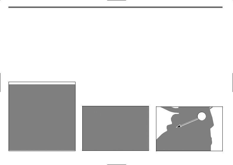
FUEL COCK (TC-TXC)
The left-side tap (2) is a screw tap: screw the ring nut (A) to close the tap, loosen the ring nut to open the tap.
WARNING*: Be careful not to touch the hot engine while operating the fuel valve.
A fuel filter is incorporated in the fuel valves. Accumulation of dirt in the filter will restrict the flow of the fuel to the carburetor. Therefore, the fuel filter should be serviced periodically.
1
1Loosen the input plug (1) on the fuel tank and close the tap;
2Remove the fuel hose (3) from the carburetor and insert the hose in a vessel;
3Open the tap and drain the fuel out of the tank;
4Remove the fuel valve by removing the screws. Wash the fuel screen filter in cleaning solvent;
5Reassemble the fuel valve in the reverse order of removal. Open the tap and check for leaks.
2
A
FUEL INJECTION ENGINE (TE-SMR) |
|
|
On vehicles which are fitted with a fuel injection engine, the |
|
|
fuel pump is built into the fuel tank and there is no tap mount- |
|
|
EN |
||
ed on the fuel supply system. The quantity of remaining fuel is |
||
indicated on the digital dash-board by the special warning |
|
|
|
||
light (see on page 16). |
|
1.Fuel tank cap
2.Fuel cock
3.Fuel hose
A. Tap ring nut


 13
13
SIDESTAND
A sidestand (1) is supplied with every motorcycle.
WARNING*: The stand is designed to support the weight of the MOTORCYCLE ONLY. Do not sit on the motorcycle using the stand for support as this could cause structural failure to the stand and could cause serious bodily injury.
Periodically check the side stand (see “Periodical maintenance card”); check that the springs are not damaged and that the side stand freely moves. If the side stand is noisy, lubricate the fastening pivot (A).
FUEL
Recommended fuel: premium grade unleaded fuel. (R.O.N. 98).
Note*: Do not continue operation if the engine pings or knocks. The engine will be damaged and could seize.
WARNING*: If "knocking" or "pinging" occurs, try a different brand of gasoline or higher octane grade.
WARNING*: Gasoline is extremely flammable and can be explosive under certain conditions. Always stop the engine and do not
smoke or allow flames |
in the |
area where the |
refueled or |
gasoline is stored. |
|
WARNING*: Do not overfill |
tank. After |
refueling, make sure the |
(1) is clo- |
sed securely. |
|
|
|
|
|
2


 14
14


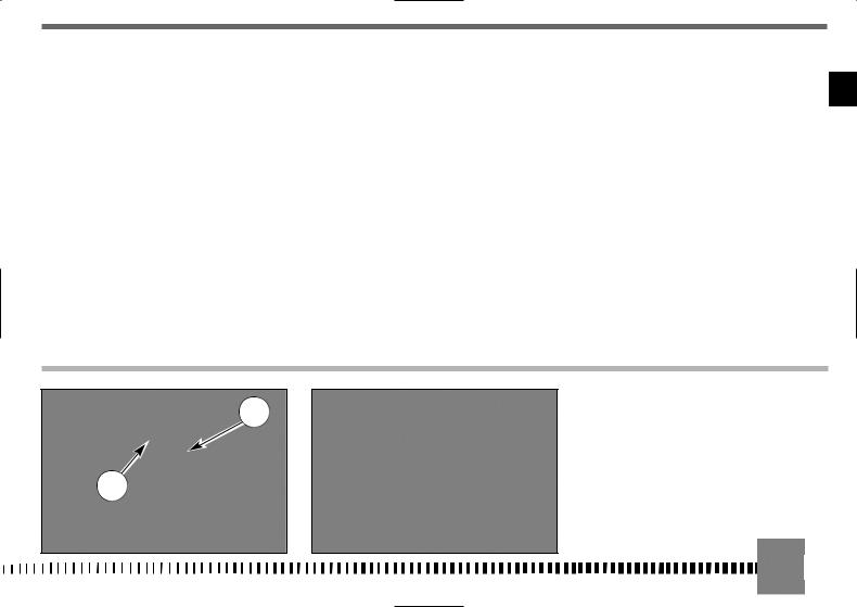
CARBURETOR CHOKE (TC-TXC)
The starter knob, located on the left side of the carburetor, is used to enrich the mixture during the engine start.
Pull out the knob to open the starter, and pull the lever upwards to close it.
The carburetor is equipped with two knobs:
1)BLACK KNOB: COLD start (°)
2)RED KNOB: WARM start (°)
(°) See page 26
COLD START (TE-SMR)
For a cold start, the models with a fuel injection engine are fitted with a black knob (3) located on the left of the throttle body.
Pull the knob outwards to open the starter and push inwards to close.
2
1
EN
15 

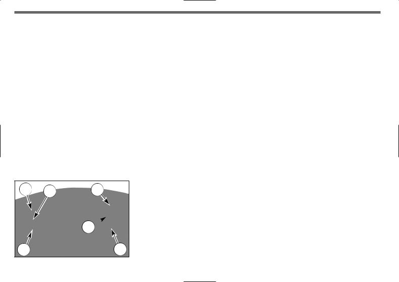
DIGITAL INSTRUMENT, WARNING LIGHTS (TE-SMR)
The motorcycle is equipped with a digital instrument; on the instrument are located 5 warning lights too: high beam, lights (with display lighting), blinkers, neutral and fuel reserve.
1- BLUE warning light “HIGH BEAM”
2- GREEN warning light ”LIGHTS”
3- GREEN warning light “BLINKERS”
4- GREEN warning light “NEUTRAL”
5- ORANGE warning light “Fuel reserve” (1,8 l - 1.58 Imp. qt - 1.9 U.S. qt)
NOTES
-After the engine starting, for the first 2 seconds, the instrument shows the version of the checking SW; after the check, the instrument shows the last planned function.
-When the motorcycle engine is OFF, the instrument doesn’t also show its functions.
-To select the instrument functions and to set to zero the functions, use the SCROLL knob (A).
-The instrument functions are the following, as shown below.
1- SPEED / ODO (figure 1, page 17)
2- SPEED / H (figure 2, page 17)
3- SPEED / CLOCK (figure 3, page 17) 4- SPEED / TRIP 1 (figure 4, page 18) 5- SPEED / STP 1 (figure 5, page 18) 6- SPEED / AVS 1 (figure 6, page 18)
7- SPEED / SPEED MAX (figure 7, page 19) 8- SPEED / TRIP 2 (figure 8, page 19)
9- SPEED / TRP 2 / CLOCK (figure 9, page 19)
10SPEED / RPM (engine r.p.m. numerical value) (figure 10, page 19)
.................
NOTE
The RPM function, shown on the vertical LED indicator, is ALWAYS on.
*IMPORTANT: Functions of the GREEN warning light (4) “NEUTRAL” in case of FUEL INJECTION SYSTEM
malfunction (contact your local HUSQVARNA Dealer)
a)With the GEARBOX NOT in NEUTRAL position: the warning light FLASHES INTERMITTENTLY.
b)With the GEARBOX in NEUTRAL position: the warning light is initially constantly ON then it FLASHES
TWICE IN RAPID SUCCESSION then returns to being constantly ON. This cycle repeats itself. After eliminating the malfunction, the warning light (4) returns to its normal operation.
2 |
4 |
1 |
3
5 |
A |


 16
16


1- SPEED (kmh or mph) / ODO / RPM (figure 1)
-SPEED: motorcycle speedmaximum value: 299 kmh or 299 mph;
-ODO: odometermaximum value: 99999 km;
-RPM: engine r.p.m. shown on the vertical LED indicator.
To replace kilometers with miles or miles with kilometers proceed as follows:
1)set to figure 1, stop the engine and push the knob SCROLL (A);
2)start the engine while pushing for 3 seconds the knob
SCROLL (A).
After the kilometers-miles or miles-kilometers setting operation, for 3 seconds, “SET” and miles/mph or km/kmh will be on.
NOTE
After the previously described operation, the ODO setting will be convert and all the others data will be reseted (the H Counter is unchanged).
2- SPEED / H / RPM (figure 2)
-SPEED: motorcycle speedmaximum value: 299 kmh or 299 mph;
-H: shows the running hours of the engine (data are saved in permanent memory every 10 minutes)- Maximum value: 9999:59;
-RPM: engine r.p.m. shown on the vertical LED indicator.
3- SPEED / CLOCK / RPM (figure 3)
-SPEED: motorcycle speedmaximum value: 299 kmh or 299 mph;
-CLOCK: clockReading from 0:00 to 23:59:59 (the data will be lost after battery detachment);
To reset the clock, push the knob SCROLL (A) for more than 3 seconds in order to increase the hours; release the knob and then, after 3 seconds, it is possible to increase the minutes;
- RPM: engine r.p.m. shown on the vertical LED indicator.
EN
17 |

4- SPEED / TRIP 1 / RPM (figure 4)
-SPEED: motorcycle speedmaximum value: 299 kmh or 299 mph;
-TRIP 1: distancemaximum value: 999.9 km (the data will be lost after battery detachment).
If the STP 1 will be set to zero, the functions TRIP 1 and AVS 1 will be set to zero too.
The function TRIP 1 is ON unitedly with the function STP 1 (*).
-RPM: engine r.p.m. shown on the vertical LED indicator.
(*): see figure 5
5- SPEED / STP 1 / RPM (figure 5)
-SPEED: motorcycle speedmaximum value: 299 kmh or 299 mph;
-STP 1: miles/kilometers covered timeReading from 0:00 to 23:59:59 (the data will be lost after battery detachment). To activate the function STP 1, push the knob SCROLL (A) for more than 3 seconds.
-1st step: function ON;
-2nd step: stop to the counters;
-3rd step: STP 1 zero-setting; TRIP 1 and AVS 1 data zero-setting;
-4th step: function ON;
-5th step: stop to the counters;
.............................
and so following NOTE
STP 1 data+TRIP 1 data=AVS 1 (*).
- RPM: engine r.p.m. shown on the vertical LED indicator. (*): see figure 6
6- SPEED / AVS 1 / RPM (figure 6)
-SPEED: motorcycle speedmaximum value: 299 kmh or 299 mph;
-AVS 1: shows the covered average speed of the motorcycle, according with a distance (TRIP 1) and a miles/kilometers covered time (STP 1) (the data will be lost after battery detachment).
NOTE
If the STP 1 will be set to zero, the TRIP 1 and AVS 1 functions will be set to zero too.
- RPM: engine r.p.m. shown on the vertical LED indicator.


 18
18 


7- SPEED / V MAX / RPM (figure 7)
-SPEED: motorcycle speedmaximum value: 299 kmh or 299 mph;
-V MAX: shows the motorcycle MAXIMUM speed (reached MAX speed), kmh or mph. Maximum value: 299 kmh or 299 mph. To set to zero V MAX, push the knob SCROLL (A) for more than 3 seconds;
-RPM: engine r.p.m. shown on the vertical LED indicator.
A
8- SPEED / TRIP 2 / RPM (figure 8)
-SPEED: motorcycle speedmaximum value: 299 kmh or 299 mph;
-TRIP 2: distancemaximum value: 999, 9 km / miles (the data will be lost after battery detachment);
To set to zero TRIP 2, push the knob SCROLL (A) for more than 3 seconds;
-RPM: engine r.p.m. shown on the vertical LED indicator.
9- TRP 2 / CLOCK / RPM (figure 9)
-TRIP 2: distanceMax value: 999.9 km / miles (the data will belost after battery detachment). To set to zero TRIP 2, push the knob SCROLL (A) for more than 3 seconds;
-CLOCK: clockReading from 0:00 to 23:59:59 (the data will be lost after battery detachment). To reset the clock, push the knob SCROLL (A) for more than 3 seconds in order to increase the hours; release the knob then, after 3 seconds, it is possible to increase the minutes;
-RPM: engine r.p.m. shown on the vertical LED indicator.
10SPEED /RPM (engine r.p.m. numerical value) (figure 10)
- |
SPEED: motorcycle speedmaximum value: 299 kmh or 299 |
EN |
|
mph; |
|
|
|
|
- |
RPM: engine r.p.m.; both vertical LED indicator and numerical |
|
|
value are on. |
|
19 

THROTTLE CONTROL
The throttle knob (1), is located on the right hand side of the handlebar. The position of the throttle control can be adjusted by loosening the two fastenig screws .
CAUTION
Do not forget to tighten the screws (A) after the adjustment.
FRONT BRAKE CONTROL
The brake control lever (2) is located on the right hand side of the handlebar. The position of the throttle control can be adjusted by loosening the two fastenig screws .
CAUTION
Do not forget to tighten the screws (B) after the adjustment.
STEERING LOCK (TE-SMR)
The motorcycle is equipped with a steering lock (1) on the R.H. side of the steering head tube.
To lock it, procede as follows:
turn the handlebar leftwards, place the key in lock and turn counterclockwise. Push the key inwards (if necessary, turn to and from). Turn the key clockwise and remove it from the lock. To unlock the steering lock, reverse the above procedure.


 20
20


R.H. HANDLEBAR COMMUTATOR (TE-TXC-SMR)
The right commutator has the following controls: 1) Engine start button
3) Engine start - stop switch (TE-SMR)
TE-SMR
TXC
1
L.H. HANDLEBAR COMMUTATOR (TE-SMR)
CONTROLS:
1) High beam flash (self cancelling)
2) Selection control High beam
 Selection control Low beam
3) |
Left turn signals (automatic return) |
|
Right turn signals (automatic return) |
To deactivate the turn signals, press the control lever after its returning to center.
4)  Warning horn
ENGINE STOP BUTTON |
(TC-TXC) |
On the left side of the handlebar, near the clutch control, is lo- |
|
cated the engine stop button. |
|
CLUTCH CONTROL |
EN |
The hydraulic clutch control lever is located on the left-hand side of the handlebar and is protected against dirt with a rubber guard.
The clutch control position on the handlebar can be adjusted by loosening the lower fastening screw (A).
CAUTION
Do not forget to tighten the screw after the adjustment.-TXC
C
T
1


 21
21


REAR BRAKE CONTROL
The rear brake control (1) is placed on the right-hand side of the motorcycle. On models TE and SMR as stop switch, during the braking action, causes the rear light to come on.
GEAR SHIFT CONTROL
The lever (1) is placed on the left-hand side of the engine. The operator must release the lever after each gear change to allow it to return to its central position before another gear change can be made.
Neutral position (N) is between first (low) and second gears. First gear is engaged by pushing the lever downwards; all the other gears are engaged, by pushing the lever upwards.
The position of the gear shift lever on the shaft can be varied by:
-loosening screw;
-pulling lever out;
-placing lever in new position on the shaft when the operation is over tighten the screw and then tightening the screw.
CAUTION*: Do not shift gears without disengaging the clutch and closing the throttle. The engine could be damaged by overspeed and shock.
WARNING*: Do not downshift when traveling at a speed that would force the engine to overrev in the next lower gear, or cause the rear wheel to lose traction.
N: Neutral |
N: Neutral |
TC |
1 |
TE-SMR-TXC |
1 |
|


 22
22


RIDING
BEFORE EVERY RIDE MAKE FOLLOWING CHECKS WARNING!
Before each ride, to prevent accidents or failures during ride, make sure to go through following list.
1.Check all fluids
A.Engine-transmission oil level
B.fuel level
C.coolant level
Make sure all caps are properly adjusted.
WARNING*: Don’t remove radiator cap when hot!
2.Check all controls
A.Throttle handgrip
B.Clutch lever
Make sure cables are not damaged and turn smoothly.
3.Check brakes
Look for brake fluid leaks and worn hoses. Check for proper functioning.
4.Check suspensions
Compress fork and rear suspensions. Look for oil leaks and ensure proper functioning.
5.Check wheels
Check spokes and look for worn bearings. Check rims and tyres.
Check tyre pressure.
6.Check chain rollers and sprockets
Check wear on chain rollers and sprockets Ensure chain is correctly adjusted and lubricated.
7.Check air filter and intake system
Check that air filter is clean
Check all rubber connections and clamps.
8.Check exhaust system
Check hook up, look for cracks Check muffler.
9.Check torque
A.Spark plug
B.Cylinder-head nuts
C.General check of torque
10.Check steering action
Check bearing play.
11.Check the electric system (TESMR). Start the engine and check that the front and rear lamps, the stop light, the turn signals the cluster warning lights and the horn are working correctly.
WARNING*: Failure to perform these checks every day before you ride may result in serous damage or a severe accident.
RUNNIN IN |
|
|
Before using the motorcycle for sporting activities run in the |
|
|
engine for two hours at least to increase the life and the per- |
EN |
|
formance of the engine. |
||
|
||
During the first half-hour of driving we advise keeping a low |
|
|
speed and avoiding sudden accelerations. Never open the |
|
|
throttle fully. |
|
|
Change the oil and carry out all the necessary maintenance op- |
|
|
erations. After the first half-hour of driving, lightly increase the |
|
|
rev number, but never run the engine at full throttle. Never |
|
|
keep low speeds when the high gears are inserted. |
|
|
Slowly drive the motorcycle for two hours before using it for |
|
|
sporting activities. |
|
CHECKS WHILE RUNNING IN
-SPOKE TENSION OF WHEELS (see page 78);
-TIGHTENING OF WHEELS (see page 92-93);
-FORK PIN TIGHTENING (see page 92);
-CHAIN ADJUSTMENT (see page 51);
-STEERING BEARING PLAY (see page 40);
-HANDLEBAR TIGHTENING (see page 92);
-ENGINE GRIP TO FRAME (see page 92);
-SUCTION FITTING GRIP (see page 92);
-HEAD AND CYLINDER NUTS GRIP (see page 92);
OFTEN CHECK THE BATTERY CHARGE CONDITION (see page 86).


 23
23 

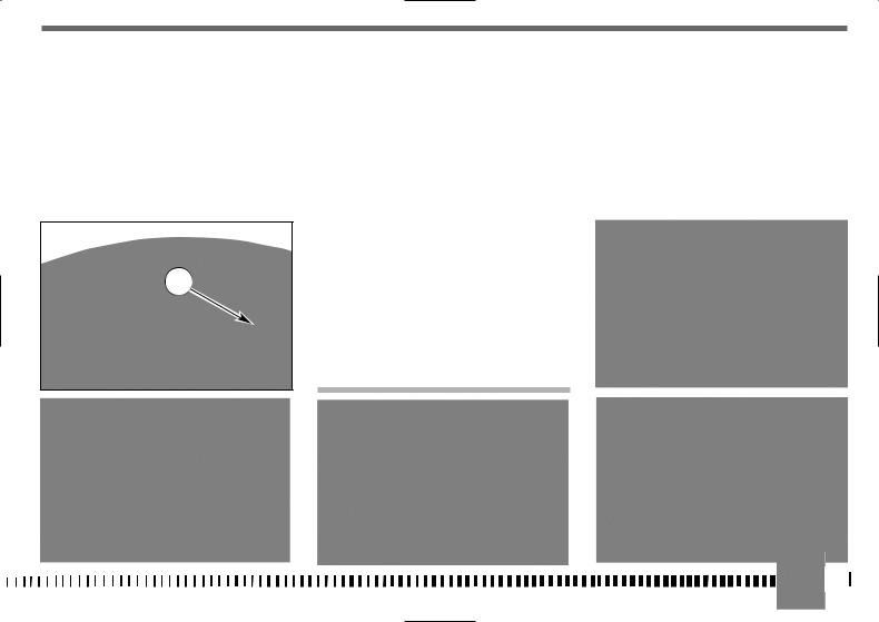
ENGINE START (TE-SMR)
With cold engine, as after a prolonged inactivity of the motorcycle or in presence of a low external temperature, proceed as follows:
1)set ignition key (1) in IGNITION position (the buzz that you hear when you turn the key to IGNITION is caused by the fuel pump which puts the feeding system under pressure);
2)pull the starter lever (2);
3)pull the clutch lever (3);
4)shift gear pedal (4) in neutral position then release the clutch control lever;
5)press the engine start-stop switch (5) then the start button
(6).
Put the start lever (2) in its initial position as soon as the engine is idling. When starting with an already warmed up engine DO NOT USE the starter. When a cold engine has just been started, do not increase revs, to ensure an
adequate oil warm-up and circulation.
NOTE
A safety switch is set on the clutch lever support. This switch allows you ONLY to start the engine with idle gearbox, or with the gear engaged and the clutch lever pulled.
IMPORTANT
NEVER START WITH DISCONNECTED BATTERY.
1 |
3 |
|
|
|
TE-SMR |
|
|
|
5 |
|
2 |
|
|
TE-SMR |
TE-SMR |
4 |
6 |
24 |
|
|
|
ENGINE START (TXC)
Make sure the fuel tap is in the OPEN position, then shift gear pedal in neutral position.
Pull the starter knob (BLACK knob (2) for cold starting*, RED knob (3) for warm starting), pull the clutch control lever, then press the engine start button (1).
Release the clutch control lever.
*: after a prolonged inactivity of the motorcycle or in presence of a low external temperature.
2
3
TXC
1
STARTING DECOMPRESSOR
Though the engine is provided with an automatic decompressor, can be necessary, in some cases (carburetor flooding or starting difficulties due to a battery inadequate charge), to use the manual starting decompressor on the L.H. side of the handlebar. In these cases, pull the lever (5) whilst simultaneously pressing the starter button, release the lever (5) keeping the button pressed and afterwards release the latter as well.
In order to adjust the lever decompressor free play (approximately 3 mm- 0.12 in.), the lever holder is provided with the adjuster (6); the adjustment can be also effected with the tightener (7) on the R.H. side of the engine (use this tightener if it is not possible to obtain the correct free play with the adjuster on the handlebar).
EN


 25
25 


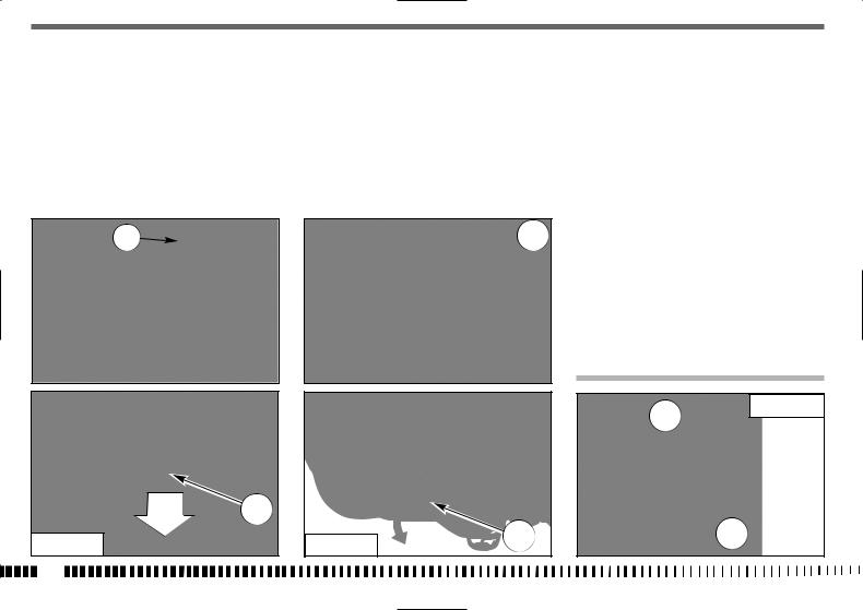
ENGINE START (TC-TXC)
Proceed as follows:
1)make sure the fuel tap (A) is in the Open position;
2)shift gear pedal (1) in neutral positio.
3)pull the starter knob (BLACK knob 2 for cold starting*, RED knob 3 for warm starting)
*: after a prolonged inactivity of the motorcycle or in presence of a low external temperature.
4)lower the starter pedal (4) until a certain resistance is noticed (piston at T.D.C.);
A |
2 |
|
|
3 |
|
TC |
1 |
TC-TXC |
4 |
|
|
||
26 |
|
|
|
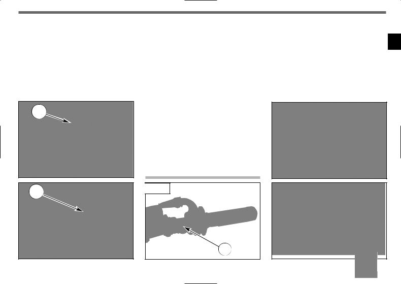
5) pull the lever (5) and lower further, by a limited stroke, the |
6) at this point, release the lever (5) and the pedal (4); |
7) in the case of COLD STARTING, completely rotate the throttle |
pedal until the abovementioned resistance is overcome |
|
(6) twice (in the case of warm starting DO NOT carry out |
(surpassing of T.D.C.); |
|
this operation); |
EN
TC-TXC
TC-TXC
4
TC-TXC


 27
27 


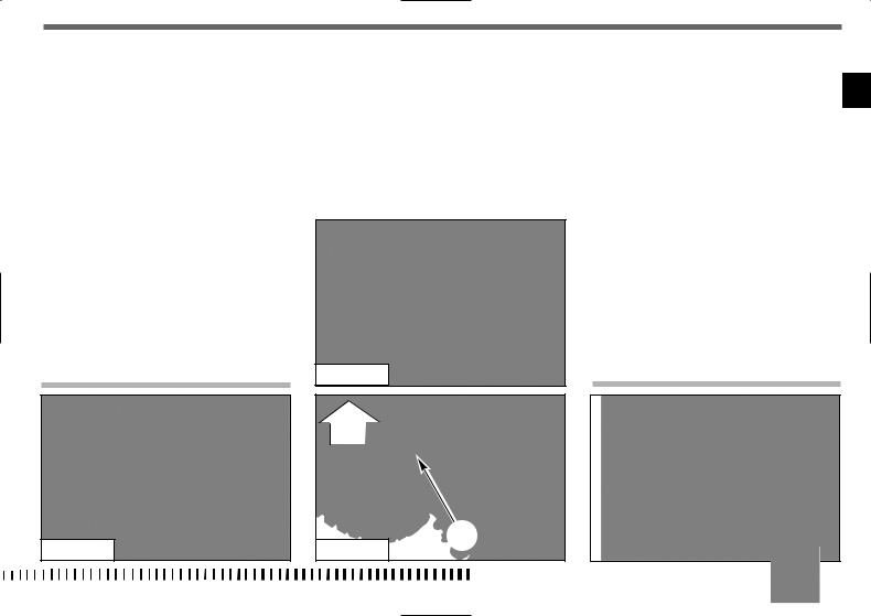
8) COMPLETELY lower the pedal (4) until the engine starts.
WARM STARTING: BEFORE MOTORCYCLE STARTING, PRESS RED CHOKE KNOB (3) ON CARBURETOR TOWARD THE INSIDE IN ORDER TO DEACTIVATE THE STARTING DEVICE.
In case the engine does not start, repeat this procedure.
IMPORTANT NOTE IN CASE OF COLD STARTS AT
LOW TEMPERATURES
It is recommended to briefly warm-up the engine at idle until, after having disengaged the starter, there is a normal response from the engine when opening the throttle.
In this way the oil can reach all the surfaces needing lubrication and the coolant will reach the necessary temperature for correct engine function.
Avoid overheating the engine.
IMPORTANT
Never accelerate the engine after a cold start.
WARNING*: Exhaust contains poisonous carbon monoxide gas. Never run the engine in a closed garage or in a confined area.
In the case of using a kick-starter, keep in mind the undermentioned note.
Kick start pedal
WARNING*: This high performance motorcycle can some times «kick back» strongly when you are starting it.
Do not attempt to start this motorcycle unless you are wearing high top heavy sided riding boots. You could seriously hurt you leg if the kickstarter kicked back and your foot slipped.
4 |
3 |
TC
 28
28

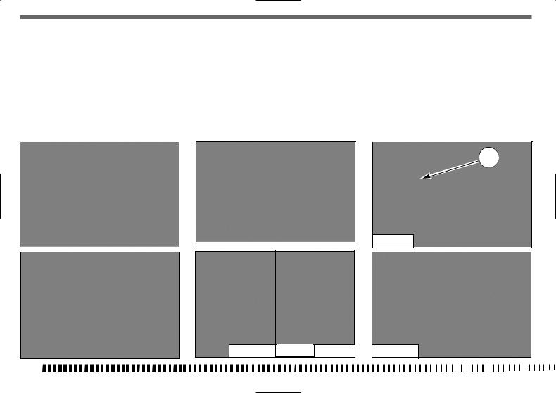
HOT START (TC-TXC)
If it is a problem to start the engine when hot, or following a fall, proceed as follows:
1)the transmission (1) should be placed in neutral;
2)pull the RED knob of the starter (2);
3) pull the clutch lever (3); |
5) Then release the clutch lever (3). |
4) push the kick-starter pedal (5) to start the vehicle. |
BEFORE MOVING OFF, DEACTIVATE THE RED |
|
|
|
KNOB (2) OF THE STARTER ON THE CARBURET- |
|
TOR. |
EN
TC |
1 |
|
|
2 |
|
TC |
4 |
|


 29
29 

STOPPING THE MOTORCYCLE AND THE ENGINE
-Close the throttle (1) completely so that the engine will help slow down the motorcycle.
-For normal braking, gradually apply both front and rear brakes while down shifting (for maximum deceleration, apply the front and rear brakes firmly).
-When stopped, pull the clutch lever and shift gear lever (2) in neutral position.
-Press the engine stop RED button (3).
-TC-TXC: close the fuel cock (4).
-TE-SMR: turn towards left the ignition key.
WARNING*: Independent use of the front or rear brake may be advantageous under certain conditions. Use caution when using the front brake, especially on slippery surfaces. Improper use of the brakes can lead to a serious crash.
WARNING*: In the event of stuck throttle or other malfunction which causes the engine to run uncontrollably, immediately depress the engine stop button and hold it down. Control the motorcycle by normal use of the brakes and steering while holding the engine stop button down.
4
TC-TXC
TE-SMR |
TC-TXC TE-SMR |
 30
30
 Loading...