


Operatorʹs manual
 Manual de usuario Manual do operador
TF230
Please read the operator’s manual carefully and make sure you understand the instructions before using the machine.
внимательно прочитайте инструкцию и убедитесь, что ‚ам все понЯтно.
переконайтесЯ, що ‚и зрозум´ли вс´ вказ´вки.
Lea detenidamente el manual de instrucciones y asegúrese de entender su contenido antes de utilizar la máquina. Leia atentamente o manual do operador e certifique se de que tenha entendido as instruções antes de usar a máquina.
GB RU UA
ES PT

1• 1 |
|
|
|
|
|
|
|
|
|
|
|
|
|
|
|
|
A |
K |
L |
|
|
G |
|
|
|
|
|
|
|
|
|
|
|
|
D |
|
|
|
|
|
E |
|
|
|
|
|
|
|
|
H |
B |
|
|
|
F |
|
|
|
|
|
|
|
|
|
|
|
|
|
|
|
|
|
N |
|
J |
|
|
I |
O |
C |
|
1 X5 |
|
5 X9 |
For tines only |
|
|
|
|
|
|
|
|
|
|
|||
|
2 X 4 |
|
|
|
|
|
|
|
|
|
6 X4 |
6 X26 |
|
|
|
||
|
|
|
|
|
|
|
|
|
|
3 X4 |
|
7 X4 |
8 X2 |
|
10 X2 |
||
|
4 X4 |
|
8 X4 |
2 X 24 |
|
9 X26 |
||
|
M |
17 |
16 |
12 |
10 |
|
|
|
|
|
|
|
|
||||
|
|
|
|
|
|
|
|
|
|
|
14 |
|
10 |
8 |
|
|
|
|
|
13 |
|
|
|
|
||
|
|
|
|
|
|
|
||

|
Right Side |
|
1 |
|
|
||
1• 2 |
|
|
|
Right Blade |
|
|
|
|
|
|
|
|
Left Blade |
|
|
|
|
|
|
|
|
|
|
|
|
|
2 |
9 |
6 |
|
|
Right Side |
4 |
||
|
|
|
|
Left Blade

9 |
6 |
2 |
|
Right Blade |
|
|
|
|
|
|
|
|
|
|
|
|
7 |
10 |
Right Side |
|
2 |
|
|
|
|
|
|
Right Blade |
|
|
|
|
|
|
|
|
|
|
9 |
Left Blade |
2 |
|
6 |
|
|
|
|
|
|
|
Right Side |
|
5 |
|
|
|
|
|
|
9 |
|
|
3 |
6 |
|
|
8 |
|
|
|
|
|
|
|
4 |
10 |
|
|
|
|
|
|
|
|
|
8 |
|
|
|
11 |
|
+ |
|
|
|
- |
|
|
Right Side |
3 |
|
|
|
|
Right Side |
|
6• |
|
|
|
|
3 |
|
|
4 |
|
|
|
9 |
12 |

13 |
|
16 |
8 |
2 |
6 |
14 |
1 |
5 |
17 |
1 |
5 |
5 |
7 |
|
153 |
8 |
2 |
6 |
|
|
18• |
1• 3 |
11 |
12 |
1• 4 |
|
|
13 |
|
|
|
1 14 |
10 |
|
|
|
|
|
|
|
7 |
|
9 |
|
|
|
|
8 |
|
|
|
6 |
|
|
|
4 |
|
|
1 |
|
|
|
|
2 |
|
|
|
5 |
|
|
3 |
|
|
|
|
|
1• 5 |

2• 1
0,6 L / 0.6
SAE-10W-30
2• 4
2• 2
0,95 L / 0.95
SAE-10W-30
2• 5
2• 7 |
2• 8 |
|
ON |
Recommend to USE Octane Value over 90
2• 3
90
3,6 L / 3,6
2• 6 |
2• 9 |
2• 10

3• 1 |
2 |
|
1 


 1,2
1,2
A B
3• 2 |
2 |
R

 1
1
A B
4• 1 |
4• 2 |


 N
N


4• 3 |

|
|
|
|
|
|
|
4• 4 |
4• 5 |
4• 6 |
||||
OFF
|
|
|
|
|
|
|
|
|
5• 1 |
|
|
|
|
|
|
||
|
|
|
|
|
|
|||
|
|
|
|
B |
|
|||
|
|
|
|
|
||||
|
|
|
|
|
|
|
|
|
OFF
A
C
5• 2
OFF
A
B

|
CONTENTS |
Contents |
|
CONTENTS |
|
Contents ...................................................................... |
2 |
KEY TO SYMBOLS |
|
Symbols ....................................................................... |
3 |
Explanation of warning levels ...................................... |
3 |
SAFETY INSTRUCTIONS |
|
General ........................................................................ |
4 |
Preparation .................................................................. |
4 |
Use .............................................................................. |
4 |
Maintenance ................................................................ |
5 |
Transport and storage .................................................. |
5 |
Fueling ......................................................................... |
5 |
ASSEMBLING AND ADJUSTMENTS |
|
Unpacking .................................................................... |
6 |
Assembly ..................................................................... |
6 |
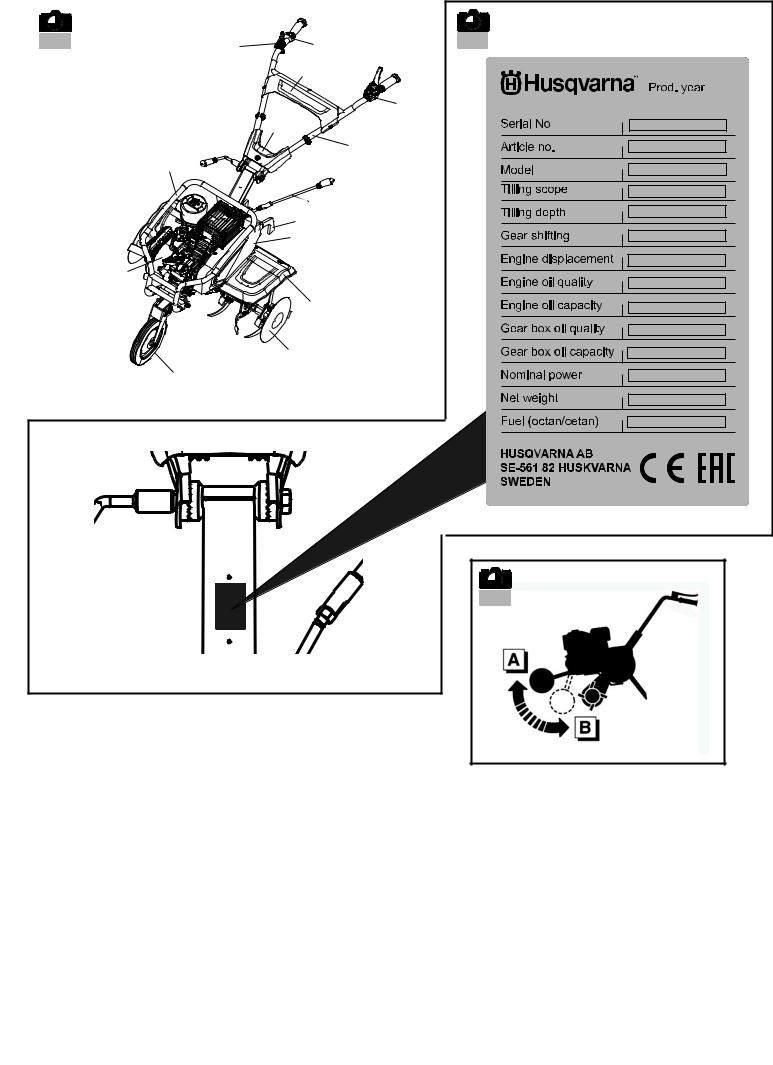
Description of the components .................................... |
6 |
Type plate ..................................................................... |
6 |
Transport wheel ........................................................... |
6 |
STARTING AND STOPPING |
|
Before starting ............................................................. |
7 |
Start the machine. ........................................................ |
7 |
Use .............................................................................. |
7 |
Stopping ....................................................................... |
7 |
Moving the machine ..................................................... |
7 |
Moving the machine ..................................................... |
7 |
MAINTENANCE AND SERVICE |
|
Maintenance schedule ................................................. |
8 |
General ........................................................................ |
8 |
TECHNICAL DATA |
|
Technical data .............................................................. |
9 |
EC Declaration of Conformity ...................................... |
9 |
English – 2
KEY TO SYMBOLS
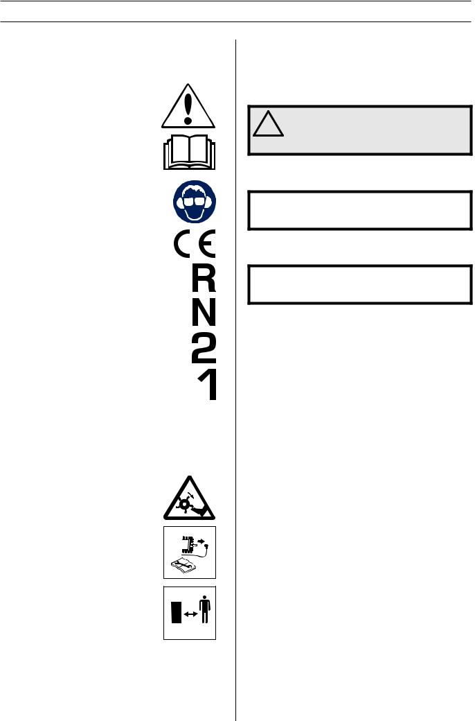
Symbols
These symbols are on the machine and in the instructions.
WARNING! Careless or incorrect use can result in serious or fatal injury to the operator or others.
Please read the operator’s manual carefully and make sure you understand the instructions before using the machine.
Use hearing protection to minimise the risk of hearing impairment.
This product is in accordance with applicable
EC directives.
Reverse
Neutral
Fast forward
Slow forward
Fast
Slow
Warning: rotating parts. Keep hands and feet clear.
The ignition lead should always be removed from the spark plug before repair, cleaning or maintenance work.
Keep your distance!
Explanation of warning levels
The warnings are graded in three levels.
WARNING!
! |
WARNING! Used if there is a risk of serious |
injury or death for the operator or damage to |
|
the surroundings if the instructions in the |
|
|
manual are not followed. |
IMPORTANT!
IMPORTANT! Used if there is a risk of injury to the operator or damage to the surroundings if the instructions in the manual are not followed.
CAUTION!
CAUTION! Used if there is a risk of damage to materials or the machine if the instructions in the manual are not followed.
3 – English
SAFETY INSTRUCTIONS
General
•These instructions are for your safety. Read them carefully.
•Read all the instructions in this operator’s manual and on the machine before you start it. Ensure you understand them and then observe them.
•If you have any problems or questions about the tiller, please contact your Husqvarna dealer for more information.
WARNING! Only use the machine for the
!purpose it is designed for, tilling the ground. Any other use may be dangerous or cause damage to the machine.
•Learn how to use the machine and its controls safely and learn to how to stop quickly. Also learn to recognize the safety decals.
•The operator is responsible for any unsafe situations or risks that people and property are exposed to.
•Never start to work with the machine before the working area is clear and you have a firm foothold. Look out for any obstacles with unexpected movement. Take great care when working on sloping ground.
•Only allow the machine to be used by adults who are familiar with its use.
•Never allow children or other persons not trained in the use of the machine to use or service it. Local laws may regulate the age of the user.
•Keep unauthorised persons at a distance. Children, animals, onlookers and helpers should be kept outside the safety zone of 20 m. Stop the machine immediately if anyone approaches.
•Never use the machine if you are tired, if you have consumed alcohol, if you are taking other drugs or medication that can affect your vision, judgement or coordination.
•Pay particular attention on hard ground.
WARNING! This machine produces an
!electromagnetic field during operation. This field may under some circumstances interfere with active or passive medical implants. To reduce the risk of serious or fatal injury, we recommend persons with medical implants to consult their physician and the medical implant manufacturer before operating this machine.
•Never use the machine when barefoot. Always wear protective shoes or protective boots, preferably with steel toes. Never wear loose-fitting clothing, jewellery or similar that can get caught in moving parts. Use hearing protection to minimise the risk of hearing impairment.
Preparation
•Inspect the working area. Remove all loose objects, such as stones, broken glass, nails, steel wire, string, etc. that could be projected by the machine.
•Check the entire machine before starting. Replace worn or damaged parts. Check that there are no fuel leaks and that all guards and covers are complete and fastened securely. Check all nuts and screws.
•Check that the electrical wires are intact and in good condition.
Use
•Never use the machine itself to transport people.
•Compliance with and strict adherence to the conditions of operation, service and repair as specified by the manufacturer also constitute essential elements of the intended use.
•Stop the engine when the machine is not in use.
•Walk with the machine, do not run.
•Pay close attention when pulling the machine towards you or reversing the direction of rotation.
•Keep a safe distance from the rotating blades, set by the length of the steering column. Keep your hands and feet away from the rotating blades.
•The engine and the exhaust system become very hot during operation. Risk of burn injuries if touched.
•Only use the machine in daylight or in other well-lit conditions.
•Do not use the machine on ground that slopes more than 20°.
•Work across slopes, not up or down.
! |
WARNING! Under no circumstances should |
you modify the original design of the |
|
machine without approval from the |
|
|
manufacturer. Always use original spare |
|
parts. Unauthorized modifications and/or |
|
accessories may lead to serious injury or |
|
death to the user or others. |
The warranty is not valid if non genuine parts are used.
Stop the engine immediately if the following occurs:
•Excessive vibration and / or noise.
•Mechanical jam preventing motor from turning.
•Difficulties to engage or disengage the clutch.
•A collision with a foreign object.
•Deterioration of the engine stop cable.
If the engine halt cable is severed, use the starter control to stop the engine. For more information see section ”Start the engine”
Allow the machine to cool down. Disconnect the HT lead from the spark plug. Check that the machine is not damaged. If the machine is damaged, hand it in to an authorized service workshop for repair.
English – 4

SAFETY INSTRUCTIONS
Maintenance
•Always stop the engine before repair, cleaning, maintenance work or when changing the tools on the machine.
•Regular maintenance is essential for safety and to maintain the levels of performance.
•Wear heavy-duty gloves when changing the tools on the machine.
•Replace the rotating blade in complete sets to keep them balanced. Always use genuine parts.
•Check that nuts and screws are tight.
•Never use a machine that has a faulty muffler. Contact an authorised service workshop.
IMPORTANT! For your own safety, do not alter the characteristics of the machine. Do not change the engine speed settings and do not run the engine at excess speed.
Transport and storage
•Allow the machine to cool before putting it in storage.
•Store the machine and fuel in such a way that there is no risk that leaking fuel or fumes can cause any damage.
•The machine should always be stored in a dry place away from open fire, sparks or intense heat.
•Fuel and fuel vapour are highly flammable. Take care when handling fuel and oil. Bear in mind the risk of fire, explosion and inhaling fumes.
•When storing and transporting fuel always use approved containers intended for this purpose.
•Do not try to lift the machine. Use a method of handling adapted to the weight of the machine and to the situation.
•Take extra care when loading it onto or off a vehicle or trailer. Use a suitable ramp.
•Use an approved trailer to transport the machine. Secure the machine with approved tightening straps. Ensure that no part of the machine are squashed or damaged by the tightening straps. It is a good idea to cover the machine.
•For more information about moving of the machine during work, see section "Moving".
Fueling
•Always stop the engine and let it cool for a few minutes before refuelling.
•Refuel in a well ventilated area with the engine turned off.
! |
WARNING! Petrol is highly inflammable. |
Exercise care and refuel outdoors. Fire, |
|
open flame and smoking are prohibited. |
Clean the area around the fuel cap. Tighten the fuel cap carefully after refuelling. If the cap is not properly tightened the cap might vibrate lose and fuel may escape from the fuel tank creating a fire hazard. Move the machine at least 3 m from the refuelling point before starting it.
•Bear in mind the risk of fire, explosion and inhaling fumes. Do not fill so that the fuel runs over. Wipe up all spillage on the ground and machine. If you spill fuel on yourself or your clothes. Change your clothes. Move the machine at least 3 metres away from the refuelling area before starting.
•The engine emits carbon monoxide, which is a colourless, poisonous gas. Do not use the machine in enclosed spaces.
5 – English

ASSEMBLING AND ADJUSTMENTS
Unpacking
Illustration: 1 • 1
IMPORTANT! Make sure to not cut the cables/wires or scratch the machine when cutting the edges of the case.
References |
Content of the case |
|
|
A |
Engine parts |
|
|
B |
Holder comp |
|
|
C |
Holder main comp |
|
|
D |
Support wheel |
|
|
E |
Drag bar |
|
|
F |
Tine cover |
|
|
G |
Tine cover bracket |
|
|
H |
Lever shifting |
|
|
I |
Blade |
|
|
J |
Blade round |
|
|
K |
Connector joint |
|
|
L |
Cover lower tidy |
|
|
M |
Tool bag |
|
|
N |
Hardware bag |
|
|
O |
Hardware bag tines only |
|
|
Assembly
Illustration: 1 • 2
WARNING! Inappropriate assembly of this
!rotary tiller could cause severe injuries. Ensure that you follow all the instructions carefully.
•Fitting the tine blades. Illustrations only shows assembly of the tine blades on the right side. Make sure that the sharp edges face one side on both right and left side tines.
(Figure 1 - 6)
•Fitting the support wheel. (Figure 7)
•Fitting the connecting joint. (Figure 8)
•Fitting the drag bar. (Figure 9)
•Fitting the handle bar. (Figure 10)
•Adjust the hight of the handle and tighten the knobs securely. (Figure 11)
•Fitting the clutch control. (Figure 12)
-Turn to proper side and fasten the bolt.
•Fitting the lower tidy cover. (Figure 13 - 14)
-Tidy the cables.
-Fit the rubber holder properly.
-Fit the cover and tighten the screws.
•Fitting the tine cover. (Figure 15 - 17)
-Do not tighten the bolt immediately after installed.
-Install all 4 bolts and nuts first, then tighten one by one.
•Fitting the shifting lever. (Figure 18)
Any dismantling operation must only be performed by an authorized service workshop.
CAUTION! After assembling the machine completly, tighten the bolts and screws with modertion. Do not overtighten.
Description of the components
Illustration: 1 • 3
1Engine
2Tine cover
3Support wheel
4Belt cover
5Blade round
6Drag bar
7Handle
8Lever shifting
9Bumper
10Clutch control
11ON/OFF switch
12Throttle control
13Upper tidy cover
14Lower tidy cover
Type plate
Illustration: 1 • 4
Transport wheel
Illustration: 1 • 5
A= Working position
B= Transport position
English – 6

STARTING AND STOPPING
Before starting
•Check the engine oil level and top up if necessary. Illustration: 2 • 1
•Check the oil level of the gear box, and top up if necessary. Illustration: 2 • 2
•Check the fuel level. Fill if necessary. Illustration: 2 • 3
-Recommended to use: Octane Value over 90.
Start the machine.
•Open the fuel tap. Illustration: 2 • 4
•Set the choke control in the A position. Illustration: 2 • 5
•Shifting lever Illustration: 2 • 6
-Put the gear shift lever in the ”N” position (neutral).
•Throttle control Illustration: 2 • 7
-Push the throttle control to full throttle position.
•Set the on/off switch to ON to attain start throttle setting. Illustration: 2 • 8
•Pull the recoil start handle Illustration: 2 • 9
WARNING! When the machine starts, remain
!within the safety zone.
•Set the choke control in the B position. Illustration: 2 • 10
Use
Illustration: 3 • 1
WARNING! Keep unauthorised persons at a
!distance. Children, animals, onlookers and helpers should be kept outside the safety zone of 20 m. Stop the machine immediately if anyone approaches.
Forwards
• Use the shifting lever to control the drive speed.
Slow
Fast
•Press down the trigger lock on the handle (A) and push the clutch lever in towards the handle (B).
•The cultivator starts to rotate when you push the clutch lever down towards the handle and stops rotating when you release the clutch lever.
Reverse
Illustration: 3 • 2
IMPORTANT! The cultivator starts to rotate when you push the clutch lever down towards the handle and stops rotating when you release the clutch lever. It is important to release the clutch lever before using reverse.
•Slide the control to ”R” position.
! |
WARNING! The use of reverse is dangerous! |
Ensure that there are no obstacles behind |
|
you and reduce the engine revs before |
|
|
engaging the clutch. |
•Press down the trigger lock on the handle (A) and push the clutch lever in towards the handle (B).
Stopping
•Release the clutch lever. Illustration: 4 • 1
•Put the gear shift lever in the ”N” position (neutral). Illustration: 4 • 2
•Move the throttle control to the MIN. position. Illustration: 4 • 3
•Use the stop switch to switch off the engine. Illustration: 4 • 4
•Close the fuel tap. Illustration: 4 • 5
Moving the machine
Illustration: 5 • 1
Support wheel
•The engine must be switched off before moving. See instructions under section Stopping.
•Set the wheel in movement position. (Figure A)
•Set the handlebars in the low position to facilitate moving the machine. (Figure B)
•Lift the blades from the ground using the handlebars and then advance forwards. (Figure C)
Moving the machine
Illustration: 5 • 2
Wheel kit
•The engine must be switched off before moving. See instructions under section Stopping.
•Change the blades to wheels when transporting. (Figure A)
•Lift the drag bar from the ground using the handlebar and then advance forwards. (Figure B)
7 – English

MAINTENANCE AND SERVICE
Maintenance schedule
The following is a list of the maintenance steps that must be performed on the machine.
|
|
|
|
Maintenance interval in hours |
|||
|
|
Daily |
|
|
|
|
|
|
|
|
20 |
50 |
100 |
|
|
Maintenance |
Illustration: |
maintenance |
hours or |
hours or |
hour or |
300 hours or |
|
|
|
before starting |
every |
evry 3 |
evry 6 |
once a year |
|
|
|
|
|
month |
months |
months |
|
|
|
|
|
|
|
|
|
Clean the machine. |
|
|
X |
|
|
|
|
|
|
|
|
|
|
|
|
Check that nuts and screws are tight and |
|
|
X |
|
|
|
|
without damage. |
|
|
|
|
|
|
|
|
|
|
|
|
|
|
|
|
|
|
|
|
|
|
|
Clean the air filter. Replace if necessary. |
4 • 6 |
|
X |
|
X* |
|
X** |
|
|
|
|
|
|
|
|
Check the engine’s oil level |
2 • 1 |
|
X |
|
|
|
|
|
|
|
|
|
|
|
|
Check the oil level of the gear box, and top up |
2 • 2 |
|
X |
|
|
|
|
if necessary. |
|
|
|
|
|
||
|
|
|
|
|
|
|
|
|
|
|
|
|
|
|
|
Check for any leakage of fuel, engine oil and |
|
|
X |
|
|
|
|
lubrication. |
|
|
|
|
|
|
|
|
|
|
|
|
|
|
|
|
|
|
|
|
|
|
|
Check the fuel level. Fill if necessary. |
2 • 3 |
|
X |
|
|
|
|
|
|
|
|
|
|
|
|
If the machine starts to vibrate abnormally, |
|
|
X |
|
|
|
|
immediately check. |
|
|
|
|
|
|
|
|
|
|
|
|
|
|
|
|
|
|
|
|
|
|
|
Change the oil and lubrication of the engine |
|
|
|
X |
|
X |
|
and the gearbox. |
|
|
|
|
|
||
|
|
|
|
|
|
|
|
|
|
|
|
|
|
|
|
Clean the fuel filter and its surrounding |
|
|
|
|
|
X |
X** |
components. |
|
|
|
|
|
||
|
|
|
|
|
|
|
|
|
|
|
|
|
|
|
|
Clean the spark plug and the spark plug cap. |
|
|
|
|
|
X |
|
|
|
|
|
|
|
|
|
Replace the spark plug. |
|
|
|
|
|
|
X |
|
|
|
|
|
|
|
|
Check/Adjust the play in the engine valves |
|
|
|
|
|
|
X** |
|
|
|
|
|
|
|
|
Clean the combustion chamber |
|
|
|
|
|
|
X** |
|
|
|
|
|
|
|
|
Check the fuel circuit |
|
|
|
|
|
|
X** |
|
|
|
|
|
|
|
|
*Clean more often in condition of use where the air is dusty or laden with aerial debris.
**Not essential except in the event of performance problems. Contact an authorised service workshop.
WARNING! Remove the foam plastic filter. Wash the filter well in tepid soapy water. After cleaning, rinse the
!filter well in clean water. Squeeze out and allow the filter to dry. NOTE! High pressure compressed air can damage the foam. Do not use compressed air or solvent with petroleum to clean the air filter.
General
WARNING! Before carrying out repair work, cleaning or inspection, the machine must be in standstill and
!turned off.
 Never make adjustments with the machine running.
Always use genuine parts.
• Never wear jewellery, watches or similar when cleaning, carrying out repair work on or inspecting the machine.
Do not modify safety equipment. Check regularly to be sure it works properly.
Always exercise care and use your common sense. Avoid all situations which you consider to be beyond your capability. If you still feel uncertain about operating procedures after reading these instructions, you should consult an expert before continuing. Contact an authorised service workshop.
English – 8

|
TECHNICAL DATA |
|
Technical data |
|
|
|
|
|
|
|
TF230 |
|
|
|
Tilling width, mm |
|
750 |
|
|
|
Tilling depth, mm |
|
150 - 300 |
|
|
|
Engine |
|
WM168FB/P-2 |
|
|
|
Fuel |
|
Petrol |
|
|
|
Fuel tank capacity, liters |
|
3,6 |
|
|
|
Oil tank capacity, litre |
|
0,6 |
|
|
|
Cylinder displacement, cm3 |
|
196 |
Max power hp (kW) @ rpm |
|
4,7 (3,45) @ 3100 |
|
|
|
Gears |
|
R, N, 2, 1 |
|
|
|
Oil capacity gearbox, liters |
|
0,95 |
|
|
|
Gross weight, kg |
|
86,5 |
|
|
|
Net weight, kg |
|
66,5 |
|
|
|
Packaging size, mm |
|
845x480x780 |
|
|
|
Certification |
|
CE, EAC |
|
|
|
IMPORTANT! When the service life of this product has been served and it is no longer used it should be returned to the dealer or to an applicable station for recycling.
IMPORTANT! We reserve the right to change specifications and designs without prior notice so as to implement improvements. Note that no legal claims are valid on the basis of information in this manual. Use only genuine parts for repairs. The warranty is not valid if non genuine parts are used.
EC Declaration of Conformity (Applies to Europe only)
Husqvarna AB, SE-561 82 Huskvarna, Sweden, tel: +46-36-146500, declares under sole responsibility that the Tillers Husqvarna TF 230 and TF 338 from serial numbers 1447000096 for TF 230, 1447000139 for TF 338, and onwards (the subsequent serial number is clearly stated in plain text on the type plate), are in conformity with the requirements of the COUNCIL’S DIRECTIVES:
of May 17, 2006 ”relating to machinery” 2006/42/EC.
of December 15, 2004 ”relating to electromagnetic compatibility” 2004/108/EC.
The following harmonised standards have been applied: EN 709:1997, A4:2009
Huskvarna December 10, 2014
Claes Losdal, Development Manager/Garden Products
(Authorized representative for Husqvarna AB and responsible for technical documentation.)
9 – English

‘ „… † ˆ…
‘одержание
‘ „… † ˆ… |
|
‘одержание ...................................................................... |
10 |
Ÿ‘ … ˆ… ‘ˆŒ‚ ‹ ‚ |
|
“словные обозначениЯ ............................................... |
11 |
оЯснение к уровнЯм предупреждений ............... |
11 |
ˆ ‘’ “Š–ˆŸ ’…• ˆŠ… …‡ ‘ ‘’ˆ |
|
бщие сведениЯ ............................................................. |
12 |
одготовка ....................................................................... |
12 |
ксплуатациЯ .................................................................. |
12 |
’ехническое обслуживание ...................................... |
13 |
’ранспортировка и хранение .................................... |
13 |
‡аправка топливом ........................................................ |
13 |
‘ Š ˆ ‘’ ‰Šˆ |
|
аспаковка ........................................................................ |
14 |
‘борка ................................................................................. |
14 |
писание компонентов ............................................... |
14 |
ˆдентификационнаЯ табличка ............................... |
14 |
’ранспортное колесо ................................................... |
14 |
‡ “‘Š ˆ ‘’ ‚Š |
|
еред началом работы ................................................ |
15 |
‡апуск .................................................................................. |
15 |
ксплуатациЯ .................................................................. |
15 |
становка .......................................................................... |
16 |
еремещение культиватора ..................................... |
16 |
еремещение культиватора ..................................... |
16 |
’…• ‘‹“†ˆ‚ ˆ… ˆ …Œ ’ |
|
ƒрафик технического обслуживаниЯ .................... |
17 |
бщие сведениЯ ............................................................. |
17 |
’…• ˆ—…‘Šˆ… „ ›… |
|
’ехнические данные .................................................... |
18 |
„…Š‹ –ˆŸ ‘ ’‚…’‘’‚ˆŸ …‘ ....................... |
18 |
Russian – 10
 Loading...