


 Loading...
SERVICE MANUAL
Designer I
Designer II
Quilt Designer
Printed in Sweden
Made in Sweden 104 72 53-26
Jan-2002
Replaces 104 72 50-26

Contence |
|
Directions for use |
4 |
ESD |
4 |
Service tools |
5 |
SETTINGS |
6 |
1. The play of the hook gear |
7 |
2. Setting the hook in relation to the feeding eccentric (after feeding) |
8 |
3. Belt tension, arm/lower shaft belt |
9 |
4. Belt tension, motor belt |
9 |
5. Setting the feeding unit sideways |
10 |
6. Basic setting - the step motor of the needle |
11 |
7. Setting of the needle in relation to the presser foot |
13 |
8. The gap between the needle and the hook |
14 |
9. The timing of the hook in relation to the needle |
15 |
10. The needle height |
16 |
11. Presser foot parallelism to the feed dog |
17 |
12.Presser foot height to the stitch plate |
17 |
13. Setting the stitch plate (the hook cover) in relation to the needle in the feeding direction. |
18 |
14. The sideways setting of the stitch plate (the hook cover) in relation to the presser foot. |
18 |
15. The height of the hook |
19 |
16.Pre-setting of the step motor for the side feeding |
20 |
17.Setting the feeding mechanism sideways |
21 |
18. Feed dog height |
22 |
19.Threading device |
23 |
20.Stitch length balance basic setting |
24 |
21. Pre-setting the step motor of the feed dog |
25 |
22.Stitch length balance |
26 |
23. Lower thread tension (thread tension of the bobbin case) |
27 |
24.Upper thread tension - Position "Norm" - Designer I |
28 |
24.Upper thread tension - Position "Norm" - Designer II and Quilt Designer |
29 |
25. Upper thread tension - Position "Embr/Dec" - Designer I |
30 |
25. Upper thread tension - Position "Embr/Dec" - Designer II |
31 |
25. Upper thread tension - Position "Decor" - Quilt Designer |
32 |
26. Upper thread guard sensor |
33 |
27. Setting the thread take-up spring |
34 |
28. Disconnection when winding the bobbin |
35 |
29. Pivot height |
36 |
SERVICE PROGRAM |
|
Service program - Designer I |
37 |
Functions of the service menu 2 - Designer I -Sensor check |
40 |
Functions of the service menu 3 - Designer I - Upper thread tension |
41 |
Calibration of the touch panel - Designer I |
42 |
Update of the memory - Designer I |
43 |
Service program Designer II |
44 |
Functions of the service menu 2 - Designer II |
47 |
Sensor check - Function of the Service menu 1 |
47 |
Functions of the service menu 3 - Designer II. |
48 |
Upper thread tension and Pivot position |
48 |
Functions of the Service Menu 4 - Designer II |
48 |
Log menu |
48 |
Calibration of the touch panel - Designer II |
49 |
Update of the memory - Designer II (Read & write unit) |
50 |
Service program for Quilt Designer |
51 |
Functions of the service menu 2 - Sensor check |
54 |
Function of the Service menu 1 |
54 |
Functions of the service menu 3 - Quilt Designer |
55 |
2 |
104 72 53-26 |
|
|

Upper thread tension - Pivot position |
55 |
||
Functions of the Service Menu 4 - Log menu |
55 |
||
Calibration of the touch panel - Quilt Designer |
56 |
||
Update of the memory - Quilt Designer (Read & write unit) |
57 |
||
DEMOUNT AND MOUNTING |
|
||
Upper rear cover |
|
|
58 |
Lower rear cover |
|
|
58 |
Front cover - Designer I |
59 |
||
Parts of the front cover - Designer I |
60 |
||
Front cover - Designer II and Quilt Designer |
61 |
||
Parts of the front cover - Designer II and Quilt Designer |
62 |
||
Presentation Unit |
|
|
62 |
Presentation Unit - d-Card Connection board |
62 |
||
Presentation Unit - Display board |
62 |
||
Touch Panel |
|
|
62 |
Base Plate |
|
|
63 |
TransformerDesigner I, Designer II |
64 |
||
TransformerQuilt Designer |
65 |
||
Circuit board - Circuit diagram - Designer I |
66 |
||
Circuit board - Circuit diagram - Designer II |
67 |
||
Circuit board - Circuit diagram - Quilt Designer |
68 |
||
Stop right circuit board |
69 |
||
Sewing head |
|
|
70 |
The step motor of the needle |
71 |
||
The step motor of the presserfoot lifter |
72 |
||
The thread tension compl. |
73 |
||
The hook cover compl, step motor house. |
74 |
||
Parts of the hook cover compl.- Designer I and Designer II |
75 |
||
Feeding unit |
|
|
76 |
Feed dog. |
|
|
77 |
The side feeding mechanism complete |
78 |
||
The side feeding mechanism step motor |
78 |
||
The feeding unit step motor |
79 |
||
Hook compl. |
|
|
80 |
Bobbin winding device |
|
81 |
|
Cover Y-slide |
|
|
82 |
Step motor cover |
|
|
82 |
Cover upper part |
|
|
83 |
Cover lower part |
|
|
83 |
Locker switch |
|
|
83 |
EMBROIDERY UNIT |
|
|
|
Embroidery unit |
- |
X-unit |
84 |
Belt tension |
|
|
84 |
Calibration of the end position, X-unit. |
84 |
||
Embroidery unit |
- |
Y-unit |
85 |
Belt tension |
|
|
85 |
Calibration of the end position, Y -unit. |
85 |
||
Hoop holder |
|
|
86 |
The hoop sensor. |
|
|
86 |
Step motor, Y-unit |
|
|
87 |
Step motor, X-unit |
|
|
87 |
FAULT FINDING |
|
|
|
Fault finding diagram D I |
88 |
||
Fault finding diagram D II |
89 |
||
Fault finding diagram D I / DII |
90 |
||
Fault finding diagram D I / DII |
91 |
||
Fault finding diagram D I / DII |
92 |
||
104 72 53-26 |
3 |
|
|
Directions for use
These service instructions are intended to be used by service workshop personnel, or by salesmen who carry out servicing their own districts. They assume a thorough knowledge of the handling of precision appliances and accessibility to service tools.
The manual is divided into two sections and covers all service operations and checks which should be carried out when making a complete overhaul of a sewing machine. The first section deals with the various settings which must be maintained to ensure that the machine functions satisfactorily.
The second section covers dismantling and mounting instructions.
The diagrams only give indication as to where the detail or mechanism is located in the machine. For more detailed information regarding the construction, etc., refer to the diagrams in the spare parts list.
ESD
ATTENTION!
It is of the utmost importance that precautions are being taken in order to avoid damage of the electronics by electro static discharges ESD (=Electro Static Discharge). To avoid that these errors arise it is important to handle loose circuit boards in a controlled way.
Always use wrist band 412 23 02-01 when servicing.
4 |
104 72 53-26 |
|
|

Service tools
A reasonable requirement in a domestic sewing machine is that it should able to sew all types of fabrics used in the home. The settings made when assembling and sewing-in the machines are those most suited to give the best results in the majority of fabrics and fabric combinations. In doing so, consideration has been given to the requirements of different markets. This does, however, mean that when sewing extreme fabrics, better results may be obtained in certain cases by altering the settings. It must be pointed out that these altered settings can cause poorer results on more normal fabrics. How
the different standard ratings are set can be seen from the description under each setting instruction. The following list of setting gauges and service tools is intended as an instruction about the special service tools needed to servicing this machine.
1. On several different occasions the needle is used as a setting gauge.
The setting ratings are adapted to needle 90. Make sure to use an undamaged needle.
2.Gauge for setting the timing of the hook in relation to the needle .
Ref. No 411 17 52-01.
3.Gauge for the feed dog lift.
Ref. No 411 49 93-01.
4.Gauge for the needle height . Ref. No 412 35 29-01.
5.Adam key - Shortened 2.5 mm Ref. No 412 27 65-01
6.Adam Key 2 mm
Ref. No 411 86 00-01
7.Adam key 1.5 mm Ref. No 411 66 89-01
8.Distance gauge 0.05-1,00 mm Ref: No. 412 38 85-01
9.Angel key Torx 6
Ref No 412 27 67-01
10. Angel key Torx 8
Ref No 412 68 04-01 |
|
11. Screwdriver Torx 10 |
|
Ref. No 412 36 48-01. |
|
12. Screwdriver Torx 20 |
|
Ref. No 412 36 49-01. |
|
13. Screwdriver Torx 25 |
|
Ref. No 412 36 50-01 |
|
14. Cable for service -Designer I |
15. Calibration of touch panel |
Ref. 412 66 04-01 |
Ref. No 412 22 33-01 |
16. Service d-Card Designer II and Quilt Designer |
|
Ref. 412 66 96-01 |
|
104 72 53-26 |
5 |
|
|

SETTINGS
23
6 |
104 72 53-26 |
|
|
Settings
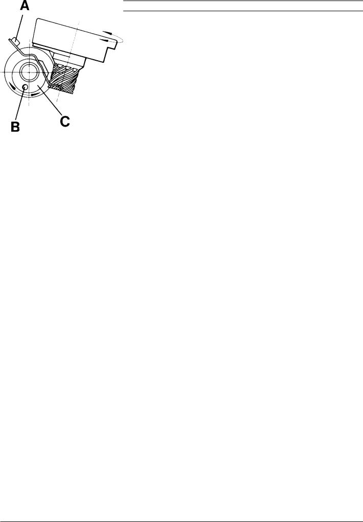
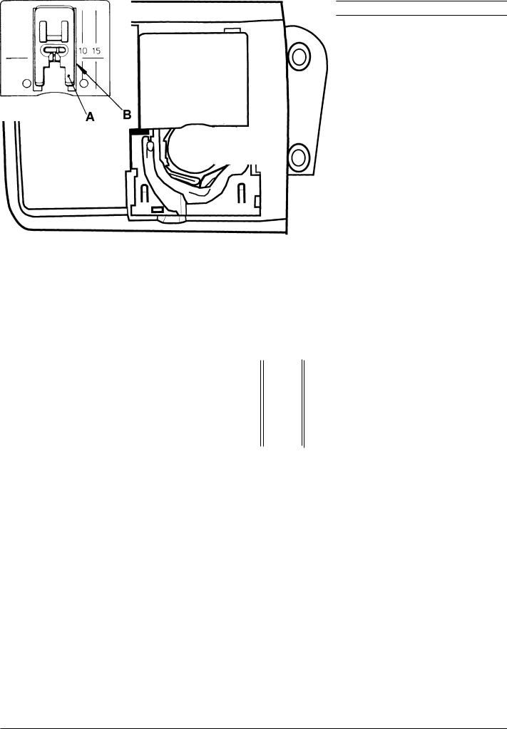
1. The play of the hook gear
It is impossible to obtain an equally large play in one rotation of the cog wheel, but it should be as small as possible at the tightest spot during the revolution.
Check
1.Rotate the hook back and forth and check the play.
2.Do this check on at least 3 different spots during the revolution of the cog wheel. (Move the cog wheel with the hand wheel).
Adjustment
1.Loosen, screw (A) in the bearing clamp
2.The play can now be adjusted by turning the eccentric bearing (C).
NOTE! The hole (B) in the bearing shall always be on the lower half.
104 72 53-26 |
7 |
|
|
Settings
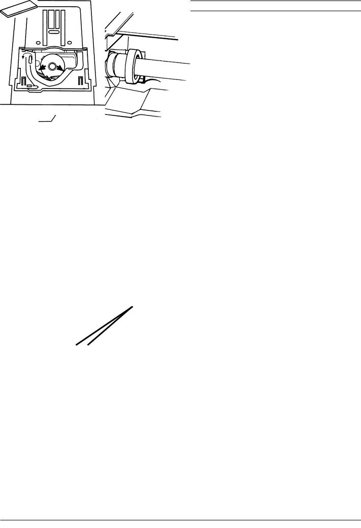
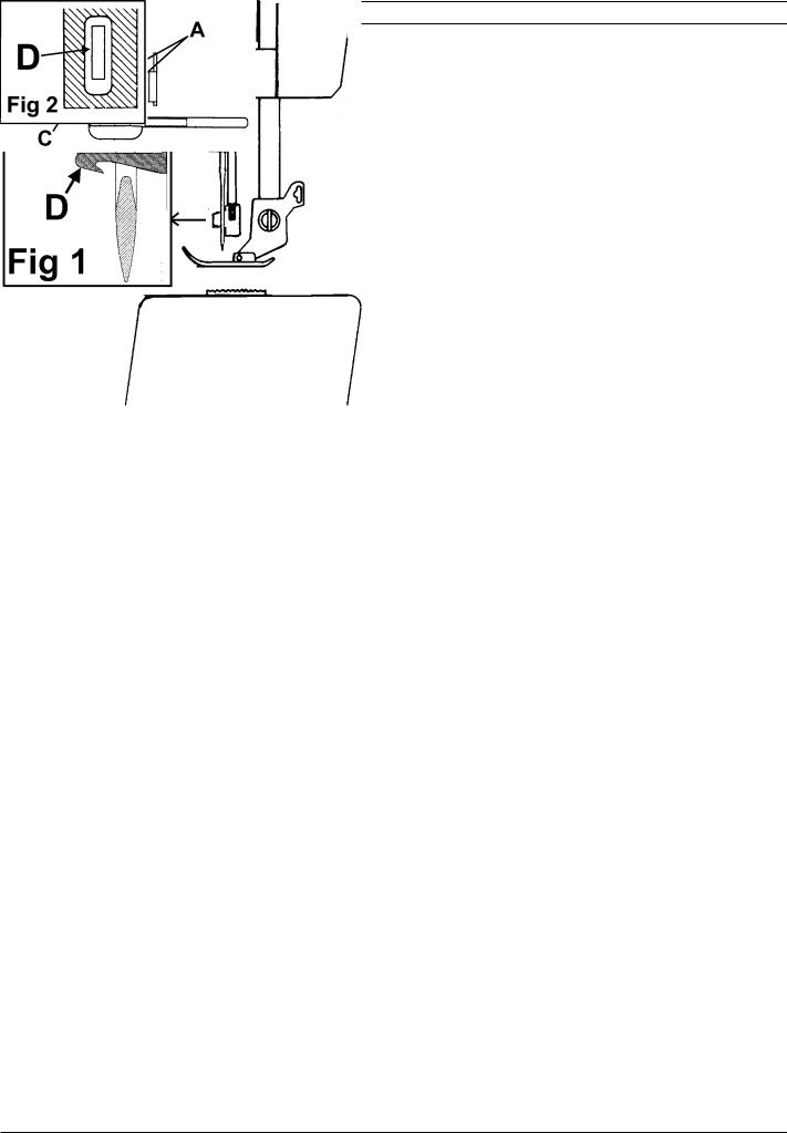
2. Setting the hook in relation to the feeding eccentric (after feeding)
Check
1.The needle shall be in its centre position, straight stitching.
2.Set the tip of hook (A) so is centred behind the needle, the tap of the worm gear should now be positioned according to fig. 1.
Note! The position of the upper pin shall be aligned with the frame opening.
Alt. Check
1. When the two taps of the worm gear are positioned according to fig. 1 the tip (A) of the hook should point straight backwards.
Note! The position of the upper pin shall be aligned with the frame opening.
Adjustment
1. Loosen screw (B). Remove the hook and set it into its correct position.
Note! The position of the upper pin shall be aligned with the frame opening.
8 |
104 72 53-26 |
|
|
Settings
3.Belt tension, arm/lower shaft belt
1.Dismount rear cover and front cover.
2.Dismount the bobbin winding device.
3.Loosen the two screws (A) of the bearing clamps.
4.The belt tension can now be adjusted by turning bearing (B) which is eccentric.
NOTE! The hole (C) should always be on the front half.
4.Belt tension, motor belt
1.Dismount rear cover .
2.Loosen the 2 screws (A) and adjust the belt tension by displacing the motor.
NOTE! The adjustment of the arm/lower shaft belt affects this adjustment.
104 72 53-26 |
9 |
|
|

Settings
5. Setting the feeding unit sideways
Check
1. The distance A and B shall be equal between the screw (C) and the edge of feeding device shaft (D).
Adjustment
1.Loosen the 2 screws in the feeding device.
2.Move the feeding device sideways until the distance A and B is equal between the screws (C) and the edge of feeding device shaft (D)
3.Tighten the screws.
10 |
104 72 53-26 |
|
|
Settings
6. Basic setting - the step motor of the needle
Check
1.Insert a new needle size 90 universal in the machine.
2.Set the needle in its upper turning position.
3.The needle should always get to the centre position, when the main switch is turned on repeatedly.
Check |
Needle point |
Go to the service program of the machine. |
|
The needle should be in its upper turning position. |
|
Touch Needle -
The needle should now take its centre position in the presser foot.
Touch Needle -
The needle shall now take its left position.
The gap between the segment (A) and the calibration stop (B) should now be zero (0 mm).
Note! The position of the eccentric.
104 72 53-26 |
11 |
|
|
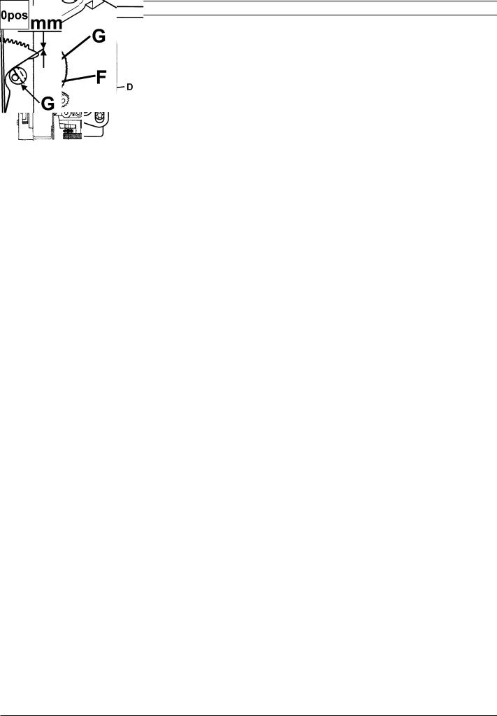
Settings
Adjustment
Go to the service program of the machine.
The needle should be in its highest position.
Touch Needle -
Loosen screw (E) in the cog wheel (D) on the step motor shaft. Turn the cog wheel until the needle is in the centre of
the presser foot.
Touch Needle -
Loosen screw (F) in the calibration stop (G) and turn it until the gap is correct (0mm).
Note! The position of the eccentric.
Touch Needle - |
, row 1 . |
Turn the screw (H) until the gap is correct (0 mm). This setting is only a sideways limitation.
Touch Needle - |
, row 1 |
The needle should now take its centre position into the needle hole of the presser foot.
12 |
104 72 53-26 |
|
|
Settings
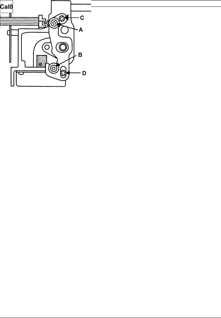
7. Setting of the needle in relation to the presser foot
Check
Insert a new needle size 90 universal in the machine.
When the machine is set at straight stitching centre position, the needle bar shall be set in such a way that a needle 90 passes through the centre of the needle hole in
the presser foot.
1 = seen from the front
2 = seen from the side
1 |
2 |
|
Adjustment |
Needle point |
|
1. Turn on the main switch |
||
|
||
Keep the machine set at straight stitching centre position |
||
alt. service menu 1, touch Needle- |
, |
|
2. Loosen the two screws (A) and (B).
Move the needle bar with the two eccentric screws (C) or (D) until the requirement is obtained.
-The length movement is adjusted by moving the eccentric screw (C)
-The side movement is adjusted by moving the eccentric screw (D)
3.Tighten the screws (A) and (B).
4.Check the setting by turning the main switch on and off a couple of times.
NOTE! "The Setting of the needle in relation to the presser foot" affects the function of "6. Basic setting - the step motor of the needle".
104 72 53-26 |
13 |
|
|

Settings
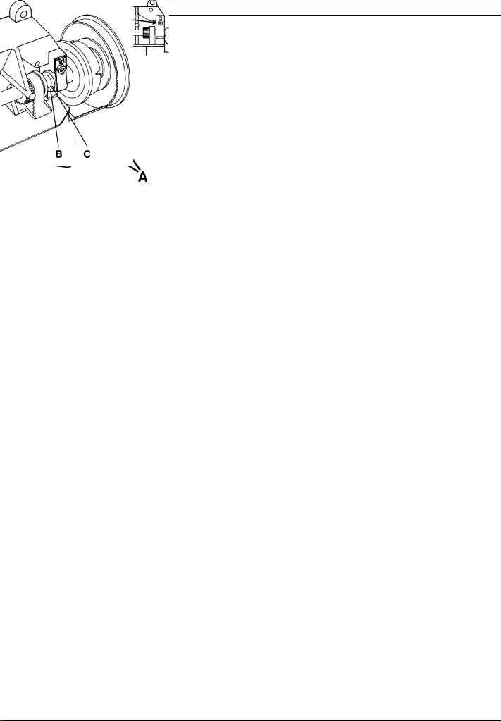
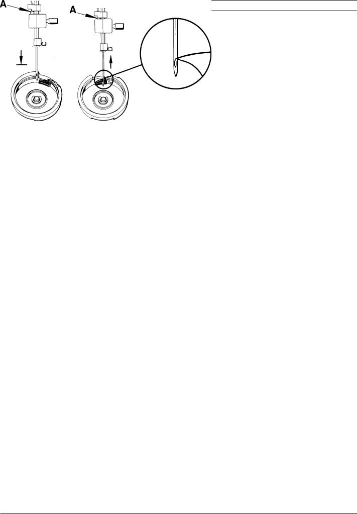
8. The gap between the needle and the hook
Check
1.Set the machine on straight stitching.
2.Insert a new needle size 90 universal in the machine.
3.Rotate hand wheel until the tip of the hook arrives behind the needle. Check the gap by pressing a small screw driver against the needle. The gap should be as small as possible, but max 0.15 mm.
Adjustment
If the gap is too large:
1.Loosen the screw (A).
2.Turn screw (B) clockwise until the needle touches the tip of the hook
3.Turn screw (A) until the gap is correct
If the gap is too small:
1.Loosen the screw (B)
2.Turn screw (A) to make the gap larger and then loosen the screw (A).
3.Turn screw (B) clockwise until the needle touches the tip of the hook
4.Turn screw (A) until the gap is correct
NOTE! Always tighten screw (A).
Check!
14 |
104 72 53-26 |
|
|
Settings
9. The timing of the hook in relation to the needle
Check
-Set a new needle size 90 universal into the machine
-Dismount the stitch plate, bobbin case holder and the bobbin case.
-Set machine on straight stitching.
-As the needle is moving upwards, the tip of the hook should pass behind the centre of the needle, when the needle is 2.5 mm above its lower turning position.
NOTE! Before any adjustment is done check that the setting
" 2. Setting the hook in relation to the feeding eccentric" is correct.
Check with setting gauge 411 17 52-01.
1.Turn the handwheel until the needle is at its lower turning position.
2.Place the setting gauge on the needle bar so that the springloaded stud (A) just touches the needle bar frame and tighten the screw.
3.Move the needle upwards with the handwheel until the springloaded stud (A) rests against its stop in the setting gauge.
4.The tip of the hook should now be behind the centre line of the needle.
Adjustment
1.Remove the blank pointed screw (B) and loosen the other 2 screws in the belt wheel of the arm shaft.
2.Repeat checking points 1, 2 and 3 with setting gauge 411 17 52-01 .
3.Hold the arm shaft and turn the hook until its tip arrives behind the centre line of the needle.
4.Tighten one of the black screws.
5.Make sure the screw descends into the groove of the shaft so that the belt wheel is placed correctly sideways.
6.Check.
7.Tighten all the screws.
104 72 53-26 |
15 |
|
|
Settings
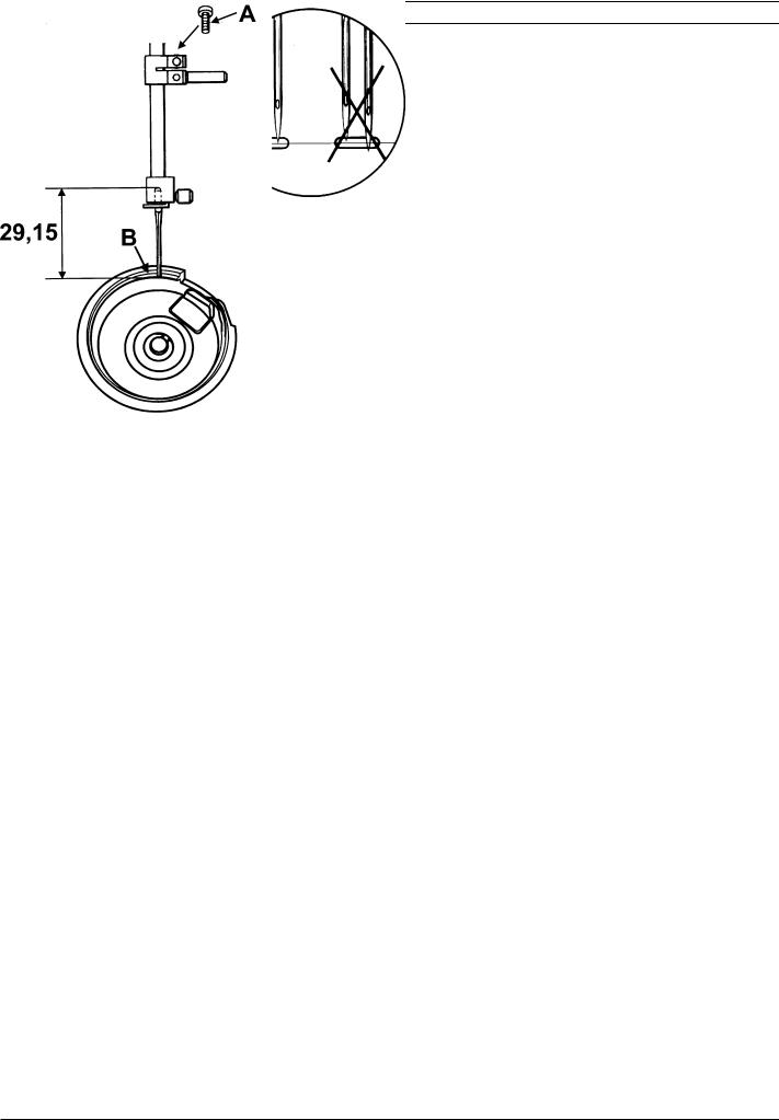
10. The needle height
Check
1.Bring the needle into its lower turning position.
2.The gap between the upper end of the needle and the surface (B) of the hook ring should be 29.15 ± 0.2 mm.
The check is executed with a polished needle 90 which is 29.15 mm long. Order nr. 412 35 29 - 01
Adjustment
1.Bring the needle to its lower turning position.
2.Loosen screw (A) and move the needle bar until the correct measure is obtained.
3.Tighten the screw.
NOTE! Check by means of a twin needle that the needle bar is not twisted. May cause jump stitches when sewing with a twin needle.
16 |
104 72 53-26 |
|
|

Settings
11.Presser foot parallelism to the feed dog
Check
The presser foot (A) should be parallel to the feed dog (B) .
Adjustment
1.Loosen screw (C) and turn the presser foot until it is parallel to the feed dog.
2.Tighten the screw (C).
12.Presser foot height to the stitch plate
Check
When the pressar foot is in its highest lifting position it shall be approx. 13 mm above the stitch plate.
Adjustment
1.Go to the service program
2.Touch Servo -
The pressar bar now takes its highest lifting position.
3.Loosen screw (C) and move the presser bar until
the presser foot is approx. 13 mm above the stitch plate.
4.Tighten the screw (C).
13
Note! This setting affects:
11. Presser foot parallelism to the feed dog
29. Pivot height
104 72 53-26 |
17 |
|
|
Settings
13. Setting the stitch plate (the hook cover) in relation to the needle in the feeding direction.
Check
1.Insert a new needle size 90 universal in the machine.
2.In the feeding direction the needle should descend right into the middle of the needle hole of the stitch plate.
14. The sideways setting of the stitch plate (the hook cover) in relation to the presser foot.
Check
The presser foot (A) should be centred and parallel to the feed dog groove (B).
Adjustment
Loosen the 4 screws of the hook cover and move it so that:
-the needle in feeding direction decends in the middle of the stitch plate.
-the presser foot is centered and parallel to the feed dog groove .
18 |
104 72 53-26 |
|
|
Settings
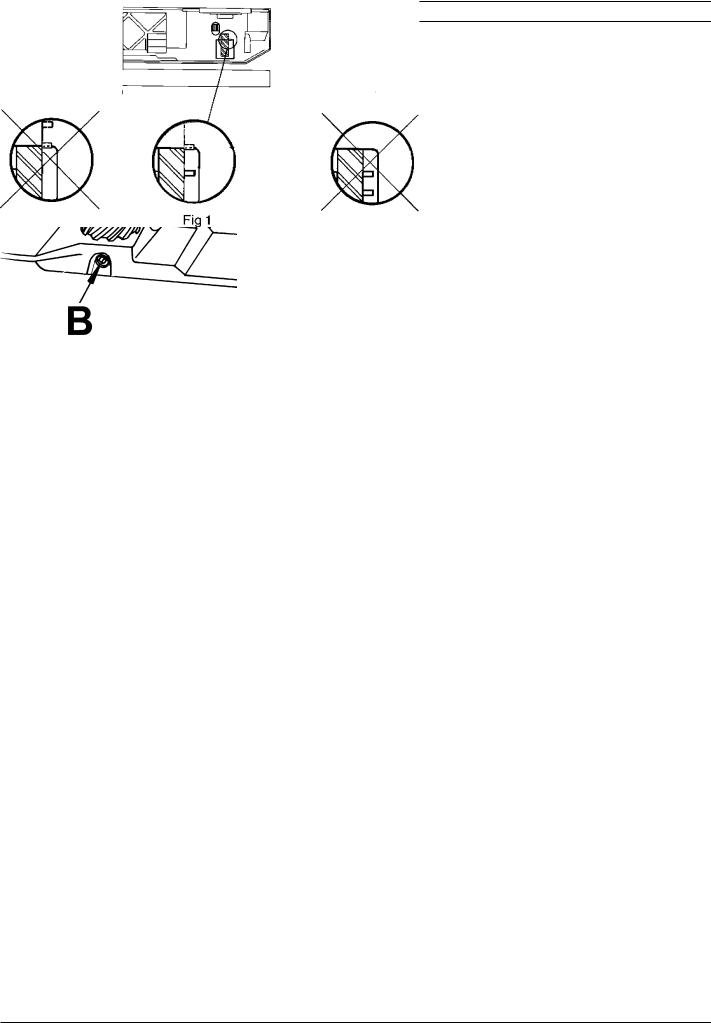
15. The height of the hook
Is checked between the bobbin case and the case holder
Check
The distance between the bobbin case and the case holder should be 0.5 mm.
The check is carried out at the tightest spot between the bobbin case and the case holder. Check at the two marked positions according to fig. 1.
Adjustment
1.Loosen screw (A).
2.The gap between the hook and its cover can now be adjusted by turning the stud (C) right or left.
-To the right, the gap becomes larger.
-To the left, the gap becomes smaller..
3.When the adjustment is done. Remove stitch plate, bobbin case holder and bobbin case.
4.Push the hook shaft (B)downwards and tighten the screw (A).
5.Re-check.
Note! This setting affects: |
1.The play of the hook gear. |
|
9.The timing of the hook and the needle |
|
10.The needle height |
Check with distance gauge 412 38 85-01.
0,5 |
mm |
|
Fig 1
B
104 72 53-26 |
19 |
|
|
Settings
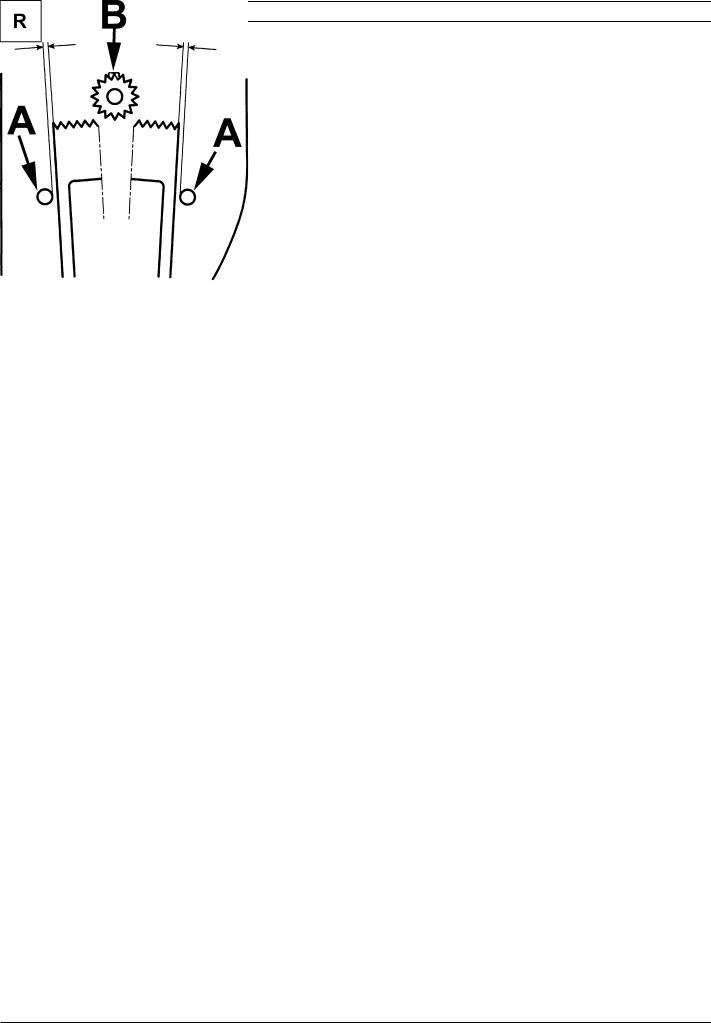
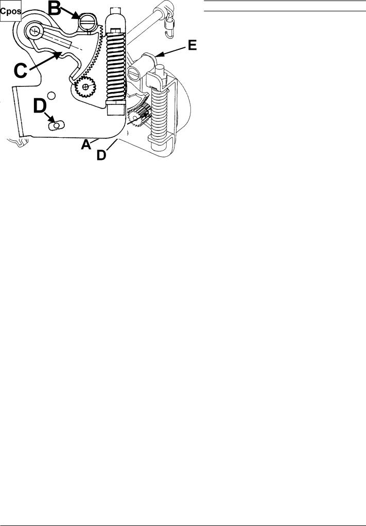
16.Pre-setting of the step motor for the side feeding
Check
1.Dismount the circuit board.
2.Dismount the side feeding unit.
3.Mount the circuit board.
4.Connect the side feeding unit. Hold the side feeding unit in your hand.
5.Touch Side-M - |
. Turn the handwheel in such a way that the cog |
segment changes between its 2 positions. |
|
Touch Side-M - |
. Turn the handwheel in such a way that the |
step motor changes between its 2 positions.
The distance between the pins (A) and the side of the segment shall be equally large in both positions.
Note ! The movement of the segment is different from left position to the right position.
Adjustment
1.Loosen screw (B).
2.Adjust the cog segment in such way that the distance (A) between the pins and the side of the segment is equally large in both positions.
NOTE! The adjustment must be done in both Side-M - |
and Side-M - |
postitions. |
3.Tighten screw (B). 4. Re-check .
20 |
104 72 53-26 |
|
|
Settings
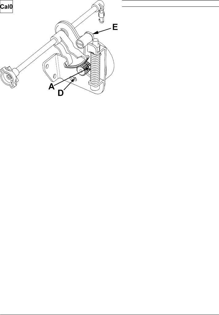
17.Setting the feeding mechanism sideways
Check
1. Go to the service program
2. Touch Side-M - |
. Turn the handwheel in such a way that the step motor |
changes between its 2 positions. The feed dog should not at any point touch the stitchplate.
3. Touch Side-M - |
. Turn the handwheel in such a way that the step motor |
changes between its 2 positions. The feed dog should not at any point touch the stitchplate.
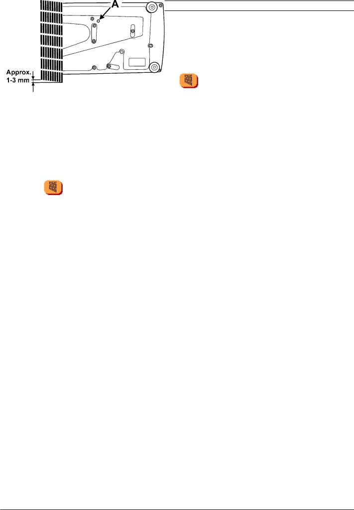
Adjusment
1.Loosen the 3 screws (A), located behind the circuit board .
2.Move the feeding device sideways until a correct position of the feed dog is accomplished by turning adjustment screw (B),located behind the circuit board .
3.Tighten the 3 screws (A).
4.Re-check the positions of the feed dog.
104 72 53-26 |
21 |
|
|
Settings
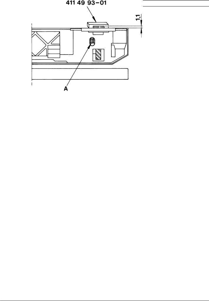
18. Feed dog height
Check
1.Bring the feed dog to its highest position.
2.The top of the feed dog should be 0.9-1.1 mm above the stitch plate.
Check with setting gauge 411 49 93-01
Adjustment
1.Bring the feed dog to its highest position.
2.Adjust with a screw driver the adjustment nut (A) until a correct feed dog height (0.9-1.1 mm) is obtained.
22 |
104 72 53-26 |
|
|
Settings
19.Threading device
Check
1.Insert a new needle.
2.Bring the needle to its highest turning position.
3.The threader hook shall go smoothly into the needles eye. See Fig 1 and Fig 2.
Adjustment
1.Loosen the the two screws (A) on the back of the threader head (B).
2.Move the thread head (B) so that the threader hook (D) does not touch the needle heightways (See fig 1)
3.Move the thread hook holder (C) so that the threader hook (D) does not touch the needle sideways (See fig 2) .
4.Tighten the screws.
NOTE! Both settings are adjusted at the same time
104 72 53-26 |
23 |
|
|
Settings
20.Stitch length balance basic setting
Check
Go to the service program.
Touch Feed- |
, the feed dog shall now stand still when the foot control is |
pressed (0-feeding).
Adjustment
1. Touch Feed- .Loosen the screw (A) of the cog wheel and turn it until the feed dog comes to a
stand-still when the foot control is pressed.
2. Turn the hand wheel until the needle arrives at its lower turning position.
3.Touch Feed- .
4. The gap between the segment (C) and the calibration stop (B) should now be Zero (0 mm). To do adjustment of the distance see "21. Pre-setting of the feeding step motor".
Note! Make sure that distance is equal on both sides of the stop screw (D) before a basic setting is performed.
24 |
104 72 53-26 |
|
|
Settings
21. Pre-setting the step motor of the feed dog
Check 1
Set the needle in its lower turning position.
The feed dog should after turning the mains switch several times on and off always reach such a position that 2.5 mm straight stitching will be obtained.
Check 2
Get into the service program.
Turn the hand wheel until the needle arrives at its lower turning position.
Touch Feed-
The gap between the segment (C) and the calibration stop (B) should now be Zero (0 mm).
Adjustment
1. Touch Feed- |
.Loosen the screw (A) of the cog wheel and turn it until the feed dog comes to a |
stand-still when the foot control is pressed.
Turn the hand wheel untill the needle arrives at it's lower turning position
Touch Feed-
Loosen screw (E). Turn the eccentric calibration stop (B) until the gap between segment (C) and the calibration stop (B) is 0 mm.
Check by first turn the hand wheel until the needle arrives at its lower turning position.
then touch Needle - |
several times. |
The motor should now run smoothly and the gap should remain 0 mm.
104 72 53-26 |
25 |
|
|
Settings
22.Stitch length balance
Check
A Both columns of the buttonhole should be of the same density. B The machine should sew a motif according to the symbol.
C The mending stitch should look according to the illustration.
(Use the mending stitch in the service menu - touch |
, row 5 ) |
Fine adjustment
Touch |
, row 5 in the service menu 1. |
Turn screw (A) until the machine sews a mending stitch according to the illustration. This adjustment may be done without dismounting the covers (see illustration.).
26 |
104 72 53-26 |
|
|
Settings
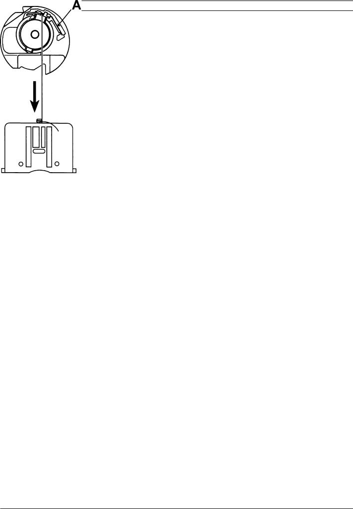
23. Lower thread tension (thread tension of the bobbin case)
Check
1.Insert a full bobbin into the bobbin case.
2.The thread tension spring of the bobbin case shall give a resistance of 12 - 20 g when pulling the thread slowly.
Adjustment
1. Turn screw (A) until the correct thread tension is obtained.
NOTE ! Before any adjustment is made remove any loose pieces of thread or fluff from the thread tension discs
104 72 53-26 |
27 |
|
|
Settings
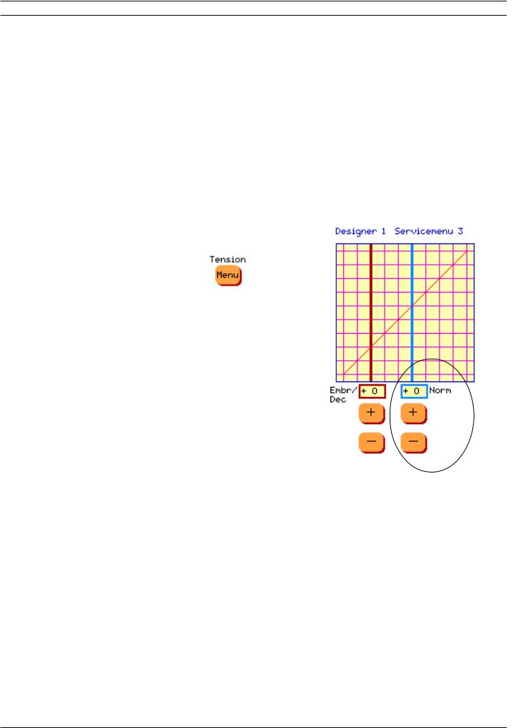
24.Upper thread tension - Position "Norm" - Designer I
Norm is for setting the higher upper thread tension
Check
A correct take-up should be obtained on straight stitch and zig-zag when the sewing advisor is set on woven medium.
Comment 1
The sewing advisor adjusts the thread tension according to the selection of fabric and sewing technique.
This is done by means of the computer and the thread tension step motor.
Comment 2
The thread tension that is set in the set menu is to be regarded as a general indication. This general indication can be raisedand lowered by means of the thread tension buttons in the Set menu and remains until the machine is turned off.
Adjustment
1. Get into the service program and select |
. |
2. To adjust the HIGHER upper thread tension
e.g on straight stitching or zick-zack sewing use "Norm" and adjust with or
or  .
.
3. "Norm" adjustments can be done between -10 and +10 if embroidery thread tension (Embr/Dec) is set on 0 (zero).
If "Embr/Dec" is not set on 0 (zero) there are limitations in the setting. The value of the setting could be higher or lower then -10 or +10.
The adjustment is automatically saved.
NOTE ! Before any adjustment is made, remove any loose pieces of thread or fluff from the thread tension discs.
28 |
104 72 53-26 |
|
|
Loading...