

Page 1
Manuale utente_Owner’s manual_Manuel d’utilisateur_Benutzerhandbuch_Manual del usuario
Page 2

HUSQVARNA MOTORCYCLES S.R.L. declina qualsiasi responsabilità per eventuali errori
in cui può essere incorsa nella compilazione del presente manuale e si riserva il diritto di ap-
portare qualsiasi modica richiesta dallo sviluppo evolutivo dei propri prodotti. Le illustrazioni
riportate sono indicative e potrebbero non corrispondere esattamente al particolare trattato.
É vietatala riproduzione anche parziale della presente pubblicazione senza autorizzazione
scritta.
To the best knowledge of HUSQVARNA MOTORCYCLES S.R.L. the material contained
herein is accurate as of the date this pubblication was approved for printing. HUSQVARNA
MOTORCYCLES S.R.L. reserves the right to change specications, equipment, or designs at
any time without notice and without incurring obligation. Illustrations in this manual are merely
for demonstration purposes and could not exactly match the detail described. No part of this
manual can be reproduced without permission in writing of the copyright holder.
HUSQVARNA MOTORCYCLES S.R.L. décline toute résponsabilité pour erreurs évuntuelles
commises pendant la rédaction du manuel et question et se réserve le droit d’apporter tous les
perfectionnements nécessaires sans avis préalable. Les illustrations gravées dans ce manuel
ne sont qu’à titre idicatif et pourraient ne pas correspondre au détail traité. Le copiage partiel
ou totale de ce manuel sans autorisation écrite est strictement interdit.
Die HUSQVARNA MOTORCYCLES S.R.L. lehnt jegliche Verantwortung für eventuelle
Fehler ab, welche bei der Zusammenstellung dieses Handbuches entstanden sein können
und behält sichferner das Recht vor, alles, was sich an Änderungen durch die Weiterentwicklung ihrer Produkte ergeben sollte, in diesem Hendbuch anzuführen. Die wiedergegebenen
Darstellungen sind indikativ und Könnten nicht genau dem betreffenden Teil entsprechen.
Die Reproduktion, auch teilweise, der vorliegenden Harausgabe ohne vorheriger schriftlicher
Genehmigung ist untersagt.
HUSQVARNA MOTORCYCLES S.R.L. no se responsabiliza por los errores debidos a la
compilación del presente manual y se reserva el derecho de aportar toda modicación necesaria para el desarrollo evolutivo de sus productos. Las ilustraciones presentadas son
indicativas y pueden no corresponderse exactamente con la pieza tratada. Se prohibe la
reproducción, también parciel, de la presente publicación sin autorización por escrito.
Page 3
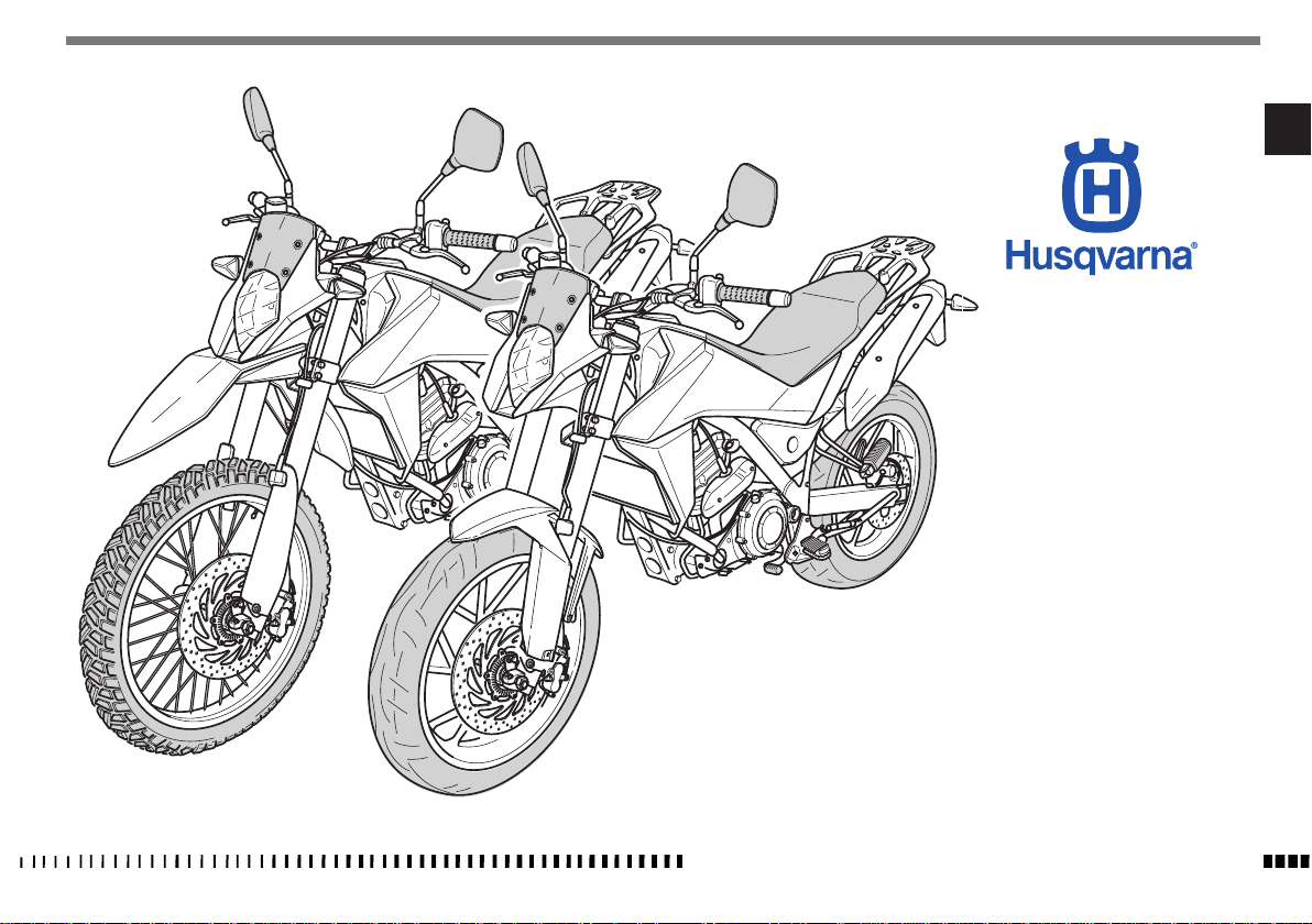
TR 650 TERRA MY13
TR 650 STRADA MY13
EN
Ed. 07-2012 - Rev. 02
Unless specified, data and prescription are referred to all the models.
SPECIFICATIONS - OPERATION - MAINTENANCE
EN - 1
Page 4

SUMMARY Page
PRESENTATION ............................................................ 3
IMPORTANT NOTICES....................................................3
INTENDED USE
GENERAL RECOMMENDATIONS
IDENTIFICATION DATA
TECHNICAL DATA
TABLE FOR LUBRICATION, SUPPLIES
MOTORCYCLE OVERALL VIEW
CONTROLS
.............................................................4
..................................... 4
.................................................. 7
..........................................................8
..............................9
..................................... 10
................................................................. 12
COMBINED DASHBOARD.............................................13
RIDING
....................................................................... 20
FUSES
........................................................................ 42
..................................................................43
APPENDIX
PRE-DELIVERY INSPECTION
ALPHABETICAL INDEX
SCHEDULED MAINTENANCE
......................................... 45
................................................. 46
.......................... APPENDIX A
lReferences to the “left” or “right” of the motorcycle
Note
are considered from the point of view of a person facing forward.
lZ: number of teeth
l A: Austria
AUS: Australia
B: Belgium
BR: Brazil
CDN: Canada
CH: Switzerland
D: Germany
E: Spain
F: France
FIN: Finland
GB: Great Britain
I: Italy
J: Japan
USA: United States of America
lUnless otherwise specified, all the data and the in-
structions refer to all Countries.
SPECIFICATIONS - OPERATION - MAINTENANCE
EN - 2
Page 5
PRESENTATION
Welcome to the Husqvarna motorcycling family!
Your new Husqvarna motorcycle is designed and manufactured to be the best in its field. The instructions in
this book have been prepared to provide a simple and
understandable guide for your motorcycle’s operation
and care. Follow the instructions carefully to obtain
maximum performance and your personal motorcycling
pleasure. Your owner’s manual contains instructions
for owner care and maintenance. The main repair or
maintenance work requires the attention of a skilled
mechanic and the use of special tools and equipment.
Your Husqvarna Dealer has the facilities, experience and
original parts necessary to properly render this valuable
service.
This “Owner’s Manual” is part and
parcel of the motorcycle, hence, it shall
remain with the motorcycle even when
sold to another user.
This motorcycle uses components designed thanks to
systems and state-of-the-art technologies which are
thereafter tested in competitions.
In racing motorcycles, every detail is verified after each
race in order to guarantee better performance at all
times.
To ensure trouble-free operation of the motorcycle, the
maintenance and inspection table found under Appendix A must be complied with.
IMPORTANT NOTICES
1) TR650 STRADA and TR 650 TERRA
models are designed for ROAD use, guaranteed free from
faults, and covered by legal warranty provided that NO
CHANGE IS MADE TO THE STANDARD SETTING and that
the intervals specified in maintenance table of Appendix
A are complied with.
2) All the motorcycles and any of their
parts used in competitions of any type
are excluded from the warranty.
EN
SPECIFICATIONS - OPERATION - MAINTENANCE
EN - 3
Page 6

IMPORTANT
In order to maintain the vehicle’s “Guarantee of Functionality”, the client must
follow the maintenance programme indicated in the user’s manual by carrying
out maintenance inspections at authorised HUSQVARNA dealers.
The cost for replacing parts and the labour required to comply with the maintenance plan is charged to the Client.
NOTE: the warranty is NULL AND VOID if
the motorcycle is rented.
WARNING*:
ALWAYS remember that all the motorcycles and their parts used in competitions of any type are excluded from the
warranty and that all modications to
standard conguration cause THE VE-
HICLE NON COMPLIANCE WITH TYPE-AP-
PROVAL REQUIREMENTS and it is hence
unsuitable for circulating on public
roads: consequently it may be used only
in “CLOSED CIRCUITS” by authorised
subjects holding the relevant driving licence or authorisation.
Important Notice
Read this manual carefully and pay special attention to
statements preceded by the following words:
SPECIFICATIONS - OPERATION - MAINTENANCE
EN - 4
WARNING*:
Indicates the possibility of severe personal injury or death if instructions are
not followed.
CAUTION*:
Indicates the possibility of personal injury or vehicle damage if instructions
are not followed.
Note*:
Gives helpful information.
Parts Replacement
When parts replacement is required, use only Husqvarna
ORIGINAL parts.
WARNING*: After a crash, inspect the
motorcycle carefully. Make sure that
the throttle control, brake, clutch and all
other systems are undamaged. Riding
with a damaged motorcycle can lead to
a serious accident.
WARNING*: Never attempt to start or
operate your motorcycle unless you are
wearing appropriate protective clothing. Always wear a motorcycle helmet,
boots, gloves, goggles and other appropriate protective clothing.
PRECAUTIONS FOR CHILDREN
WARNING*:
l Park the vehicle where it is unlikely
to be bumped into or damaged.
Even slight or involuntary bumps can
cause the vehicle to tip over, with sub-
sequent risk of serious harm to people or children.
l To prevent the vehicle from tipping
over, never park it on soft or uneven
ground, nor on asphalt strongly heated by the sun.
l Engine and exhaust pipes become
very hot during riding. Always park
your motorcycle where people or children can not easily reach these parts,
in order to avoid serious scalds.
l Do not leave the vehicle unattended
with the engine running or the key in
the ignition.
INTENDED USE
This motorcycle has been manufactured so as to withstand standard road stresses.
GENERAL RECOMMENDATIONS
Read these general recommendations carefully before
using the vehicle.
Pannier and top boxes
WARNING*:
Overloading and lack of loading uniformity can jeopardise the running stability of the motorcycle.
Do not exceed indicated total weight
and keep to the load warnings.
- Adapt the adjustment of the spring preload, of the
shock absorber and of the tyre pressure to total
weight.
- Make sure the weight is uniformly shared out to the
left and right.
Page 7
- The heavier objects must be positioned at the bottom
and internally.
- Keep to the max. load and top speed shown on the
pannier warning plate.
- Keep to the max. load and top speed shown on the
top box warning plate.
Electronic immobiliser
By means of a loop antenna on the ignition switch, the
motorcycle electronics read the data recorded in the
vehicle key. The control unit only allows starting the
engine if the key has been recognised.
- Always keep the spare key separate from the ignition key.
- The spare key and the ignition key are available
only from HUSQVARNA dealers. The dealer must determine the legitimacy of the purchase because the
keys are part of a security system.
Carbon monoxide
Only run the engine in an open or very well ventilated
area. If you do work in an enclosed area, make sure
you use a fume extraction system.
WARNING*:
Exhaust emissions contain carbon monoxide, a poisonous gas which can cause
loss of consciousness and even death if
inhaled.
Parts of the vehicle that become hot
Before working on the engine and the exhaust unit,
wait for them to cool down; while the vehicle is running, these parts become very hot and remain hot for
some time after turning off the engine.
CAUTION*:
Risk of burns - work with caution and
wear suitable PPE if necessary.
Fuel
WARNING*:
The fuel used to power internal combustion engines is highly flammable
and explosive.
Refuel in ventilated areas with the
engine switched off; do not smoke
and avoid contact between the fuel
and naked flames, sparks, etc. that
may cause an explosion.
Do not dispose of fuel in the environment.
Keep out of reach of children.
CAUTION*:
Do not tilt the vehicle excessively
since this may cause fuel to leak.
Engine
In some cases, coolant may become inflammable and
if burnt, produce invisible flames which cause burns.
WARNING*:
Do not spill coolant onto hot components like the engine or exhaust pipe,
etc. since it may ignite.
During maintenance work, wear latex
gloves.
Never leave the coolant in open containers in areas accessible to children and
animals since it is toxic.
DO NOT remove the radiator cap when
the engine is hot; the coolant is pressurised and may cause scalding.
Engine oil
CAUTION*:
Do not dispose of oil in the environment
since it is highly polluting.
Keep out of reach of children.
Wear latex gloves since prolonged contact with the skin can cause serious
damage.
Send used oil to special authorised
recyclers in accordance with the legal
requirements in force in the country
where the vehicle will be used.
EN
SPECIFICATIONS - OPERATION - MAINTENANCE
EN - 5
Page 8
Brake fluid
WARNING*:
Brake fluid is highly corrosive and may
damage the rubber and painted parts of
the vehicle.
While performing maintenance work,
protect your eyes by wearing special
goggles and wear protective gloves.
In the event of accidental contact with
the eyes, rinse them with plenty of
clean, running water and seek medical
advice immediately.
Keep out of reach of children.
Battery
WARNING*:
Recharge the battery in well ventilated
areas since the battery produces toxic,
highly inflammable gases when being
recharged; do not smoke or use naked
flames or sparks.
The liquid in the battery is highly corrosive. If it comes into contact with the
skin, rinse thoroughly with running water. It is extremely important to protect
your eyes because even a small amount
of liquid can cause irreversible damage
to the eyes.
If it comes into contact with the eyes,
rinse thoroughly with clean, running
water and if swallowed accidentally,
drink plenty of water or milk.
In all cases, seek medical advice immediately.
The battery liquid is corrosive and
should not be poured onto the painted
or rubber parts.
The battery liquid is highly polluting.
DO NOT dispose in the environment;
at the end of its service life, take the
battery to the special authorised recycling centres in accordance with the legal requirements in force in the country
where the vehicle will be used.
Keep out of reach of children.
SPECIFICATIONS - OPERATION - MAINTENANCE
EN - 6
Page 9
IDENTIFICATION DATA
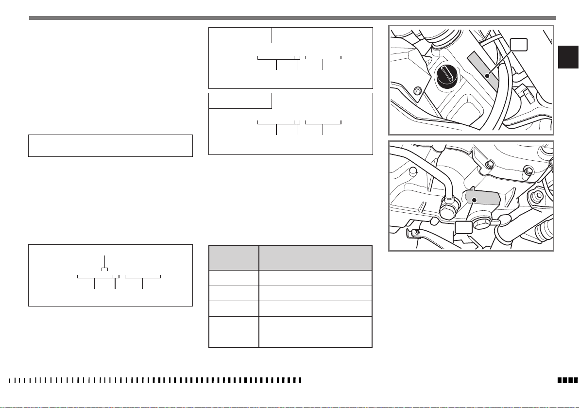
The engine identification number is stamped on the bottom RH side of the crankcase whereas the motorcycle serial number is stamped on the steering tube.
Always quote the number stamped on the
frame when ordering spare parts or requesting further
details about your vehicle and note it on this booklet.
TERRA USA
ZKH0H12A#DV000001
STRADA USA
(l) (▲)
1
EN
(
♦
)
CHASSIS NUMBER
VEHICLE IDENTIFICATION NUMBER (V.I.N.)
The full 17-digit serial, or Vehicle Identification Number, is
stamped on the steering tube (R.H. side).
(l) = Model designation
(▲) = Model Year (2013)
(♦) = Progressive no.
(■)
ZKH0H11A#DV000001
(
♦
(l) (▲)
)
ZKH0H12B#DV000001
(l) (▲)
Version
Model
(■)
A
C
D
E
F
TR 650 Terra (43 kW)
TR 650 Terra (43 kW - ABS)
TR 650 Terra (35 kW - ABS)
TR 650 Strada (43 kW - ABS)
TR 650 Strada (35 kW - ABS)
(
♦
)
2
1. Chassis serial number
2. Engine serial number
SPECIFICATIONS - OPERATION - MAINTENANCE
EN - 7
Page 10
TECHNICAL DATA
ENGINE
Single cylinder, 4 stroke engine with four valves
Cooling ....................liquid and electric fan
Bore
........................3,937 in (100 mm)
Stroke ........................3,268 in (83 mm)
Displacement ................39,787 in3 (652 cm
Compression ratio .......................12,3:1
Starting
..............................electric
Type of fuel ............unleaded fuel 95ROZ/RON
TIMING SYSTEM
Double overhead camshaft chain operated; 4 valves
Valve clearance (with engine cold)
Intake
.......... 0,009 ÷ 0,011 in (0,23 ÷ 0,28 mm)
Exhaust ......... 0,015 ÷ 0,017 in (0,38 ÷ 0,43 mm)
LUBRICATION
Dry sump with tank integrated in the chassis and cartridge oil filter.
IGNITION
Electronic with adjustable advance (digital control)
Spark plug type
..............“NGK” MAR9A-J-G06
Spark plug electrode gap ......0,024 in (± 0,004 in)
0,6 mm (± 0,1 mm)
FUEL SYSTEM
Electronic injection feed
PRIMARY DRIVE
Drive gear on crankshaft ....................Z 37
Driven gear on clutch housing ................Z 72
Transmission ratio .......................1.946
CLUTCH
Multidisc in oil bath with mechanical control
TRANSMISSION
3)
With front couplings always engaged
Transmission ratio
1st gear ........................2.750 (33/12)
2nd gear ........................1.750 (28/16)
3rd gear ........................1.313 (21/16)
4th gear ........................1.045 (23/22)
5th gear ........................0.875 (21/24)
SECONDARY DRIVE
Transmission sprocket .....................Z 16
Rear wheel sprocket .......................Z 47
Transmission ratio .......................2.938
Drive chain dimensions ...........520KR0 112 links
FINAL RATIOS
1st gear ..............................15.722
2nd gear ..............................10.005
3rd gear ..............................7.506
4th gear ...............................5.974
5th gear ...............................2.898
CHASSIS
Single frame, in round, rectangular and ellipsoidal steel
pipes; rear steel chassis
FRONT SUSPENSION
Upside down type hydraulic fork .................
. . . . . . . . . . . . . . . . . . . . . ø 1.81 in (46 mm) fork legs
Wheel travel ...................7.48 in (190 mm)
REAR SUSPENSION
Hydraulic monoshock (adjustment of spring preload and
rebound hydraulic damping)
Wheel travel
...................7.48 in (190 mm)
FRONT BRAKE
Ø 11,811 in (300 mm) fixed disc with hydraulic control
and floating calliper
REAR BRAKE
Ø 9,449 in (240 mm) floating wave disc with hydraulic
control and floating calliper
WHEELS
TR 650 STRADA
Front
.....................in light alloy: 2.5”x19”
Rear ......................in light alloy: 3”x17”
TR 650 TERRA
Front ..... with spokes and aluminium rim: 1.85”x21”
Rear
. . . . .with spokes and aluminium rim: 3”x18” (no ABS)
. . . . . . with spokes and aluminium rim: 3”x17” ( ABS)
TYRES
TR 650 STRADA
Front
....................110/80 R19” M/C 59 V
Rear ....................140/80 R17” M/C 59 V
SPECIFICATIONS - OPERATION - MAINTENANCE
EN - 8
Page 11
Cold tyre pressure (Rider only)
Front .....................2.2 kg/cm2 (31.29 psi)
Rear .....................2.0 kg/cm2 (28.45 psi)
Cold tyre pressure (Rider and passenger)
Front .....................2.2 kg/cm2 (31.29 psi)
Rear .....................2,5 kg/cm2 (35.56 psi)
TR 650 TERRA
Front ...............90/90 21” M/C 54 H TL (ABS)
90/90 21” M/C 54 S (no ABS)
Rear ................140/80 17” M/C 59 H (ABS)
140/80 18” M/C 70 S (no ABS)
Cold tyre pressure (Rider only)
Front .....................2.0 kg/cm2 (28.45 psi)
Rear .....................2.5 kg/cm2 (35.56 psi)
Cold tyre pressure (Rider and passenger)
Front .....................2,0 kg/cm2 (28.45 psi)
Rear .....................2,8 kg/cm2 (39.82 psi)
DIMENSIONS, WEIGHT, CAPACITY
Wheelbase .................55,055 in (1500 mm)
Total length (STRADA) ....... 88,504 in (2248 mm)
Total length (TERRA) ......... 89,252 in (2267 mm)
Overall width ................34,843 in (885 mm)
Max. height (STRADA) ........ 47,441 in (1205 mm)
Max. height (TERRA) .......... 48,15 in (1223 mm)
Saddle height (STRADA) ........33,858 in (860 mm)
Saddle height (TERRA) .........................
34,449 in (875 mm) (no ABS - 18”)
34,055 in (865 mm) (ABS - 17”)
Minimum height off ground (STRADA) .............
9,843 in (250 mm)
Minimum height off ground (TERRA) ...............
10,472 in (mm 266) (no ABS 18”)
10,118 in (257 mm) (ABS 17”)
Weight, without fuel (STRADA). ...390,218 lb (177 kg)
Weight without fuel. (TERRA) .......383,604 (174 kg)
Fuel tank capacity including reserve ...3,08 Imp. Gall.
3,698 U.S. Gall.
l 14
Fuel reserve ...............approx. 0,55 Imp. Gall.
0,66 U.S. Gall.
2.5 l
Coolant tank capacity .............0,255 Imp. Gall.
0,306 U.S. Gall.
1.16 l
Oil and oil filter replacement ......... 0,44 Imp. Gall.
0,528 U.S. Gall.
2.0 l
Topping up oil between minimum and max. level .....
0,055 Imp. Gall.
0,066 U.S. Gall.
l 0.25
TABLE FOR LUBRICATION, SUPPLIES
Engine, gearbox and primary drive lubricating oil
............CASTROL POWER1 RACING SAE 10W-50
Engine coolant .........CASTROL MOTORCYCLE COOLANT
Brake fluid ..........CASTROL RESPONSE SUPER DOT 4
Grease lubrication ............. CASTROL LM GREASE 2
Secondary drive chain lubrication
....................
CASTROL CHAIN LUBE RACING
Electric contact protection
............. CASTROL METAL PARTS CLEANER
SPECIFICATIONS - OPERATION - MAINTENANCE
EN
EN - 9
Page 12
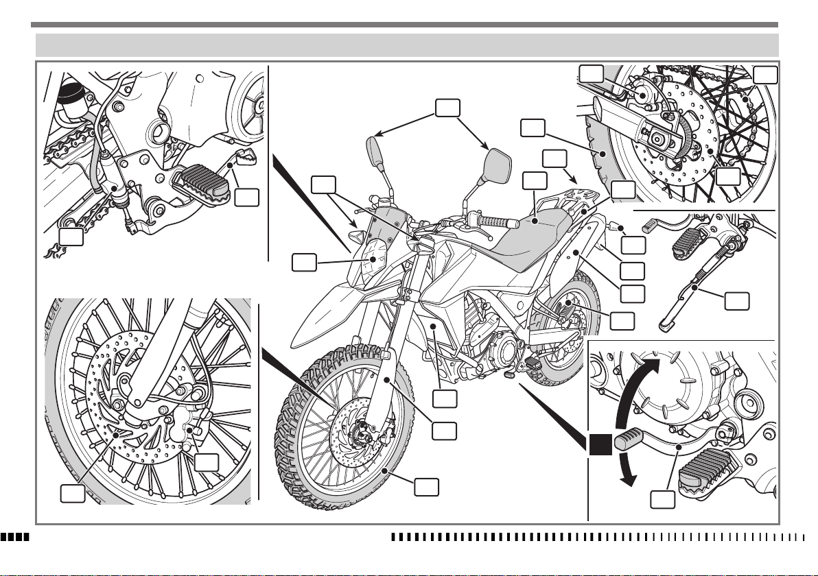
MOTORCYCLE OVERALL VIEW
17
19
7
13
8
11
18
16
14
12
21
10
15
22
9
6
20
5
23
4
4
3
2
N
3
1
2
SPECIFICATIONS - OPERATION - MAINTENANCE
EN - 10
1
5
Page 13
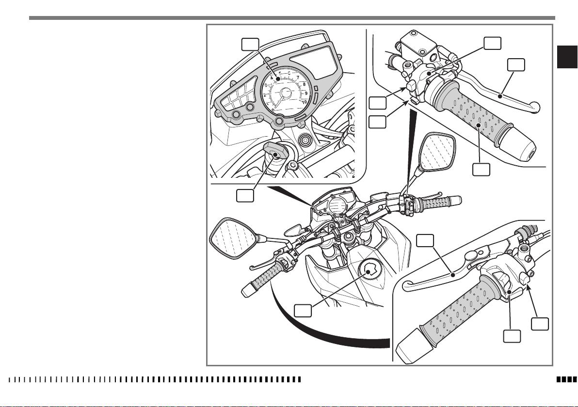
LEGEND
1. Front wheel
2. Left-hand front brake disc
3. Right-hand front brake calliper
4. Front fork
5. Gear shift pedal (the first gear is engaged by
pushing lever downwards; for other gears push it
upwards. The neutral gear is between the first and
second gear)
6
. Side stand
7. Rear sprocket
8. Rear wheel
9. Number plate holder
10. Rear turning indicators
11. Tail light
12. Saddle
13
. Rear-view mirrors
14. Front turning indicators
15. Headlight
16. Rear brake control pedal
17. Rear brake master cylinder
18. Rear brake disc
19. Rear brake calliper
20. Passenger footrests
21
. Passenger grab handles
22. Exhaust silencers
23. Radiator
24. Fuel tank filler cap
25. Digital dashboard
26. Ignition switch
27. Right-hand switch
28. ENGINE STOP button (emergency stop)
29. Engine start button
30. Front brake control lever
31. Throttle twistgrip
32. Clutch control lever
33. Left-hand switch
34. ABS switch (where fitted)
26
25
24
28
29
32
31
27
33
30
EN
34
SPECIFICATIONS - OPERATION - MAINTENANCE
EN - 11
Page 14
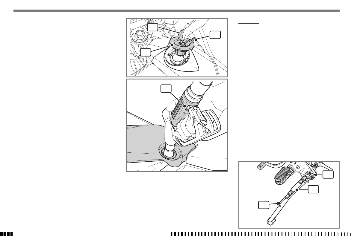
CONTROLS
REFUELLING
Use UNLEADED petrol with octane rating of 95 or
higher only.
CAUTION*:
Using leaded fuel causes permanent
damage to the catalytic converter
which loses its effectiveness.
WARNING*:
Fuel is extremely flammable and can be
explosive under certain conditions. Always stop the engine and do not smoke
or allow flames or sparks in the area
where the motorcycle is refuelled or
fuel is stored.
WARNING*:
Do not overfill the tank. Refer to the
lower mark on filler. After refuelling,
make sure the tank cap (3) is closed securely.
- Lift the flap (1), insert the key (2), turn it counterclockwise and remove the tank cap (3).
- Fully insert the fuel pump nozzle (4) in the tank
before refuelling (see figure).
- After refuelling, replace the cap (3) turning it the
opposite way from when it was removed.
SIDE STAND
2
1
3
4
A side stand (1) is supplied with every motorcycle.
To lower it, operate on the grip with your foot (2).
WARNING*:
The stand is designed to support the
WEIGHT of the MOTORCYCLE ONLY. Do
not sit astride the motorcycle using the
stand for support as this could cause
structural failure to the stand resulting
in serious injury.
WARNING*:
The stand does NOT have automatic retraction.
The stand has a rotary type switch that
turns off the engine if a gear is engaged
when the stand is lowered.
Periodically check the side stand (see “Scheduled Maintenance Chart”); make sure that the springs are not
damaged and the side stand freely moves. If the stand is
noisy, lubricate and check the retention pin (A).
A
1
SPECIFICATIONS - OPERATION - MAINTENANCE
EN - 12
2
Page 15
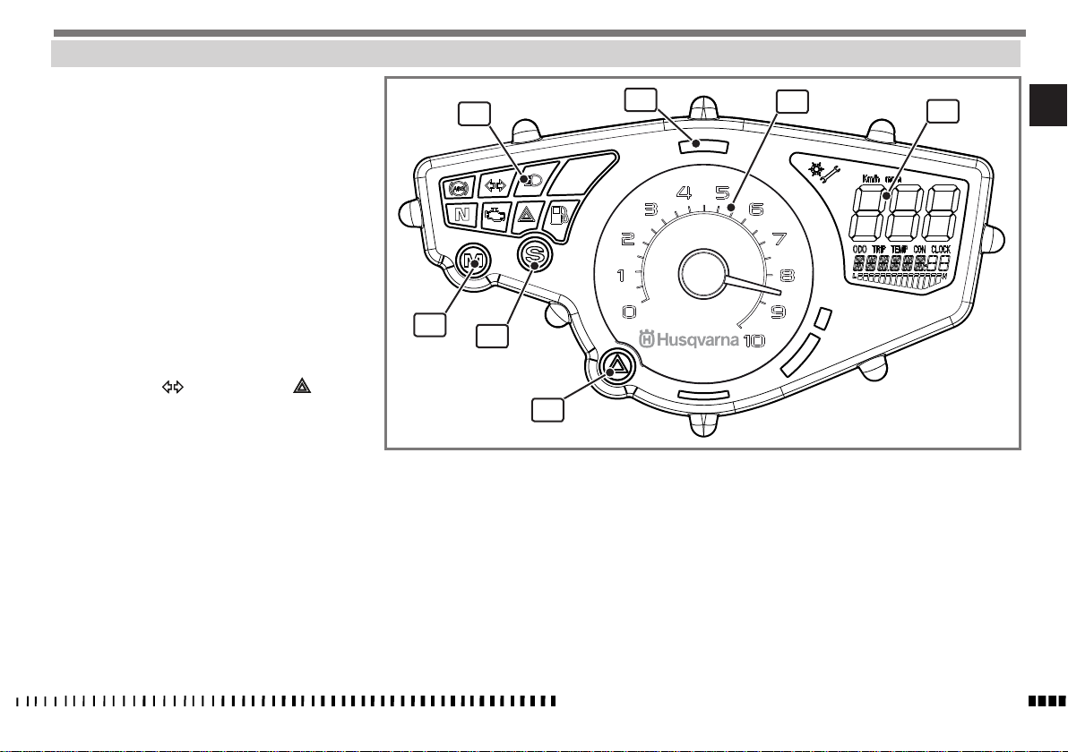
COMBINED DASHBOARD
The motorcycle has a combined dashboard divided into
the following areas:
1. Warning lights (see “ Description of warning
lights”).
2. Multifunction display (see “ Description of multi-
function display”).
3. Rev meter
Indicates the engine rpm.
4. Alarm system warning light (optional) (RED).
5. “MODE” button
6. “SET” button
This displays the various functions of the multi-
function display (see “Description of multifunction display”).
7. “HAZARD” button
When this is pressed, the turning indicators,
warning light and warning light flash
at the same time.
Press it again to deactivate the hazard warning
lights.
1
5
6
7
4
3
2
EN
SPECIFICATIONS - OPERATION - MAINTENANCE
EN - 13
Page 16
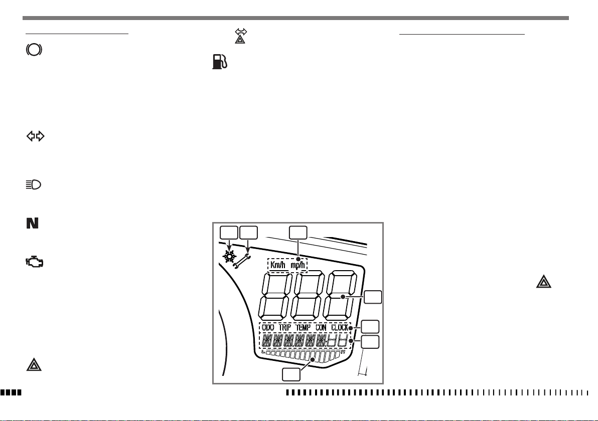
DESCRIPTION OF WARNING LIGHTS
ABS
“ABS” warning light.
When turning the key to the “ON” position, the
warning light starts blinking and keeps on blinking until the vehicle starts moving forward. If
the system works properly, the warning light
turns off; if the self-diagnosis finds a failure in
the system, or if the system is deactivated, the
warning light stays on.
Turning indicator warning light (GREEN)
This flashes when the turning indicators have
been turned on or the “HAZARD” button has
been pressed.
High beam warning light (BLUE)
This lights up permanently when the high beam
is on.
Neutral warning light (GREEN)
This lights up permanently when the motorcy-
cle is in neutral.
Engine diagnosis warning light (ORANGE)
This lights up permanently when the engine
ECU has diagnosed malfunctioning.
There are two types of fault:
- Critical fault: the engine switches off and
you must contact your HUSQVARNA dealer.
- Fault with emergency operating: the engine
operates with reduced performance to allow
you to reach the nearest HUSQVARNA dealer
to have the fault checked.
and the turning indicators when switch
has been pressed.
Fuel reserve warning light (ORANGE)
This comes on when there are approximately 3
litres of fuel left in the tank.
You need to refuel.
Note *:
the fuel light normally switch off a few time after
the fuel refilling operation.
1 2 3
4
5
6
DESCRIPTION OF MULTIFUNCTION DISPLAY
1. “ICE” indicator:
This appears when the external temperature is
lower than 3°C or 37.4°F
2. “SERVICE” indicator:
This indicates that it is time for a service.
Contact your HUSQVARNA dealer to have sched-
uled maintenance work carried out.
3. km/h or mp/h odometer scale indicator (see
“setting units of measurement”)
4. Speed indicator
5. Display parameters:
This field is used to individually set the param-
eters below that will be displayed in (6).
ODO = Odometer / Total mileage
TRIP = Odometer / Partial mileage
(to set the functions, see “Setting parameters”)
TEMP = Air temperature (AIR BOX) / Coolant
temperature
CON = Actual fuel consumption / Average con-
sumption.
CLOCK = Clock ( see “Clock adjustment”).
6. This displays the parameter set in (5).
7. This lights up in sequence from left to right as the
coolant temperature increases.
In case of overheating, the indicator lights
up steady and the bar (7) flashes.
“HAZARD” warning light (RED)
This flashes together with the warning light
SPECIFICATIONS - OPERATION - MAINTENANCE
EN - 14
7
Page 17
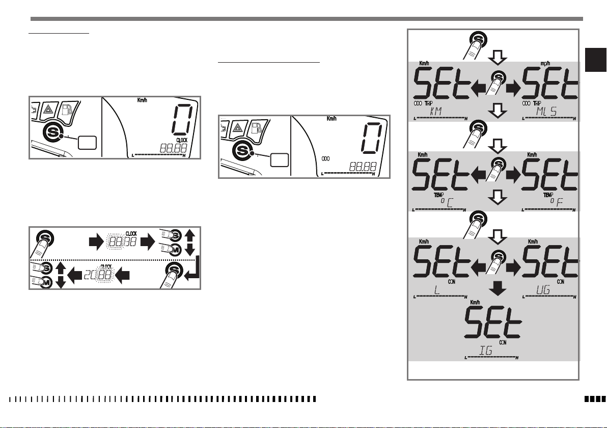
CLOCK ADJUSTMENT
The clock must be set when the motorcycle is stationary
and the key is set to ON.
The clock is set to 24 hours.
- Press the “S” button (1) until the word “CLOCK” appears on the display.
is automatically memorised after 10 seconds.
SETTING UNITS OF MEASUREMENT
The units of measurement must be set when the motorcycle is stationary and the key is set to ON.
- Press the “S” button (1) until the word “ODO” or
“TEMP” appears on the display.
> 4”
EN
1
- Press the “S” button for more than 4 seconds and the
hours will flash on the display.
- The value of the hours increases by one unit each time
you press the “S” button.
- The value of the hours decreases by one unit each time
you press the “M” button.
> 4”
4”<
- Press the “S” button for more than 4 seconds to memorise the hours set and the minutes will flash on the
display.
- The value of the minutes increases by one unit each
time you press the “S” button.
- The value of the minutes decreases by one unit each
time you press the “M” button.
- To memorise the time once you have set it, press the
“S” button for more than 4 seconds. If not, the setting
1
- Press the “S” button for more than 4 seconds. The word
“SET” appears on the display and the unit of measurement currently in use.
- Press the “S” button once to change the unit of measurement. Once you have selected the unit of measurement, press the “S” button” for more than 4 seconds to
confirm the set data and go onto the next scale.
The following units of measurement can be set:
Km / mp = the display will show:
- the speed in “km/h” or “mp/h” ;
- the total distance covered in “km” or “mp”
- the partial “TRIP” distance covered in “km” or “mp”.
Temperature = °C / °F
Quantity of fuel:
L = (litres) - UG = US/GAL - IG = IM/GAL
- To quit the “SET” stage once you have made your last
setting, press the “S” button for more than 4 seconds. If
not, the program automatically quits after 10 seconds.
SPECIFICATIONS - OPERATION - MAINTENANCE
> 4”
> 4”
EN - 15
Page 18
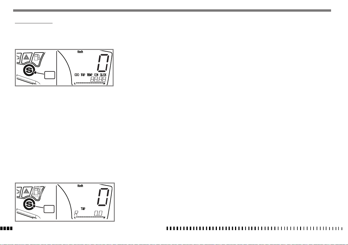
SETTING PARAMETERS
With the dashboard on, press the “S” button (1) to display the various display functions:
ODO ; TRIP ; TEMP ; CON ; CLOCK
1
The “ODO”, “TEMP” and “CLOCK” functions are for display purposes only.
TRIP function:
When this function is activated, press the “S” button for
more than 4 seconds to reset and start a new partial
count of the kilometres /miles subsequently travelled.
When this function is set after the fuel reserve light has
come on, press the “S” button “S” (1) for more than 4
seconds to display fuel consumption (in litres or gallons
depending on the unit of measurement you have selected) from when you go onto fuel reserve.
CON function:
When this function is activated, press the “S” button for
more than 4 seconds to reset and start a new count of the
litres/ gallons consumed from when average consumption (L/100 km) has been reset.
1
SPECIFICATIONS - OPERATION - MAINTENANCE
EN - 16
Page 19
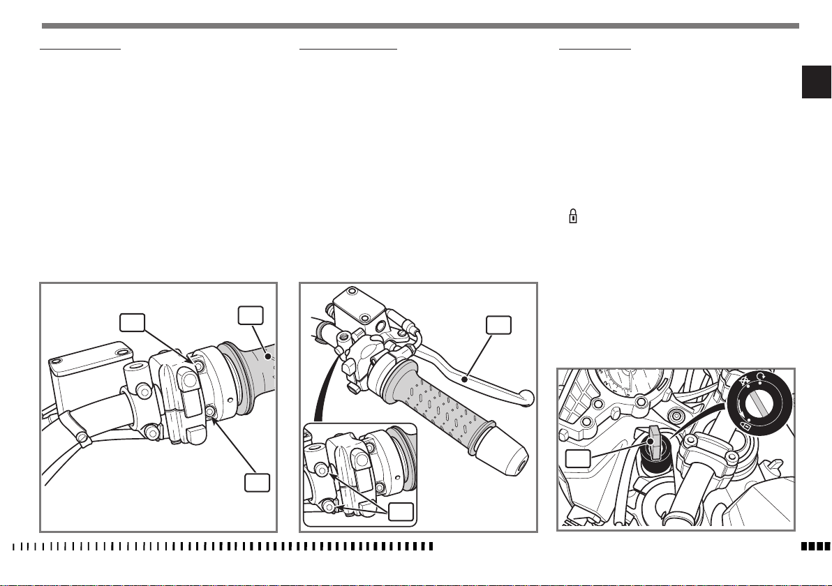
THROTTLE CONTROL
The throttle twistgrip (1) is located on the right-hand side
of the handlebar. The position of the control on the handlebar can be adjusted by loosening the two retaining
screws (2).
CAUTION*:
Do not forget to tighten the screws (2)
after adjusting.
FRONT BRAKE CONTROL
The brake control lever (1) is located on the right-hand
side of the handlebar. The position of the control on the
handlebar can be adjusted by loosening the two retaining screws (2).
WARNING*:
After adjustment, turn the handlebar as
far as possible to the right and make
sure that the lever does not touch the
bodywork.
A stop switch, during the braking action, causes the stop
light on the tail light to come on.
CAUTION*:
Do not forget to tighten the screws (2)
after adjusting.
IGNITION SWITCH
The ignition switch has three positions:
EN
"OFF" position:
Key removal and engine stop positions
"ON" position:
From the OFF position, turn the key (1) clockwise to the
ON position; the ignition, parking lights and utilities are
activated and the engine can be started;
“ ” position:
Steering lock position (see steering lock)
2
1
2
2
SPECIFICATIONS - OPERATION - MAINTENANCE
1
ON
OFF
PUSH
1
EN - 17
Page 20
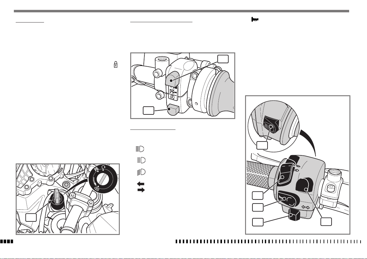
STEERING LOCK
The motorcycle has a steering lock on the ignition.
To lock it, proceed as follows:
- Turn the handlebar as far as possible to the left .
- Insert the key in the ignition (1), press the key
down, turn it from the “OFF” position to the “ ”
position and then remove it.
- To unlock the steering, follow the steps for locking in
reverse order.
RIGHT-HAND HANDLEBAR SWITCH
The right-hand switch features the following controls:
1) Engine start button
2) Engine KILL SWITCH.
2
1
L.H. HANDLEBAR SWITCH
The left-hand handlebar switch contains the following
commands:
High beam flasher (self-cancelling).
1)
5) Horn.
1
ON
OFF
PUSH
Low beam switch.
3) Left-hand turning indicators.
Right-hand turning indicators .
To deactivate the turning indicators, press the control
lever after it is returned to the centre.
2) High beam switch.
1
SPECIFICATIONS - OPERATION - MAINTENANCE
EN - 18
4) ABS switch (where fitted)
By pressing the button for over 3 seconds, the
“ABS” antilock braking system is engaged or disengaged.
ABS
2
5
3
4
Page 21
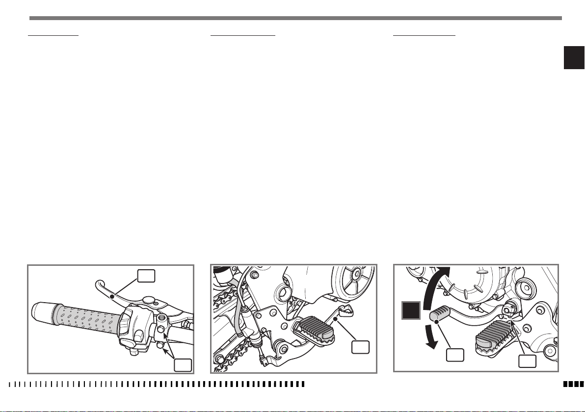
CLUTCH CONTROL
The clutch control lever (1) is located on the left-hand
side of the handlebar.
The position of the clutch control on the handlebar can be
adjusted by loosening the retaining screws (2).
WARNING*:
After adjustment, turn the handlebar
as far as possible to the left and make
sure that the lever does not touch the
bodywork.
A "STOP" switch on the clutch lever support allows you
to start the engine when the motorcycle is in gear or the
clutch lever is pulled (the stand must be off the ground).
CAUTION*:
Do not forget to tighten the screws (2)
after adjusting.
REAR BRAKE CONTROL
The rear brake control (1) is placed on the right-hand
side of the motorcycle.
A stop switch, during the braking action, causes the stop
light on the tail light to come on.
GEAR SHIFT CONTROL
The lever (1) is placed on the left-hand side of the en-
gine. The operator must release the lever after each gear
change to allow it to return to its central position. Neutral
position (N) is between the first and second gears.
First gear is engaged by pushing the lever downwards;
for other gears push it upwards.
The position of the gear shift lever (1) on the shaft can
be varied. To do this, loosen the screw (2), pull the lever
out and place the lever in a new position on the shaft.
Tighten the screw once operation is completed.
WARNING*: Do not push the lever too
far down!
CAUTION*: Do not shift gears without
disengaging the clutch and closing the
throttle. The engine could be damaged
by overspeed.
WARNING*: Do not downshift when
travelling at a speed that would force
the engine to overrev in the next lower
gear, or cause the rear wheel to lose
grip.
EN
1
1
2
SPECIFICATIONS - OPERATION - MAINTENANCE
5
4
3
2
N
1
1
2
EN - 19
Page 22
INSTRUCTIONS FOR USING THE MOTORCYCLE
NOTE*: If you are not familiar with operating a motorcycle, read the instructions in the “CONTROLS” section before
riding this motorcycle.
PRE-RIDE CHECKS
Any time you ride your motorcycle, make a general in-
spection rst and proceed to check the following:
- check fuel level and engine oil level;
- check brake fluid level;
- check the steering by turning the handlebar both ways,
fully home;
- check the pressure of the tyres and their state of wear;
- motorcycle road holding may already not be perfect
once the minimum tread thickness required by the law
is reached. Replace the tyres once the minimum tread
thickness is reached.
- check the chain tension;
- check the throttle control and adjust it, if necessary;
- turn the ignition switch to ON position: check dashboard display lighting;
- check that parking lights, low beam and high beam
come on, as well as the relevant warning light;
- operate the turning indicators and check that the warning light comes on;
- check if the rear stop light is functioning.
Running the engine in correctly is essential for ensuring
engine longevity and functionality.
Bendy roads and gradients are ideal for running in the
engine, brakes and suspension effectively.
Remember that new tyres need running in as well in
order to ensure best road-holding characteristics; drive
cautiously for the rst 100 km (62.5 mi).
SPECIFICATIONS - OPERATION - MAINTENANCE
EN - 20
Vary your riding speed during the running in period.
This ensures that components operate in "loaded" conditions and then "unloaded" conditions, allowing the
engine components to cool.
Although it is important to stretch engine components
during run-in, make sure you do not overdo it.
Optimum performance during acceleration is only obtained after the rst
1000 km (625 mi) of running in.
Follow these guidelines:
do not fully open the throttle grip abruptly at low engine
speeds, either during or after the running in period.
During the rst 100 Km (62 miles) use the brakes gently,
avoiding sudden or prolonged braking.
This allows the brake pad friction material to bed in correctly with the brake discs.
During the rst 1000 km (625 miles), never exceed 5000
rpm (see table).
After the rst 1000 km (625 mi), have
the checks indicated in the Scheduled
Maintenance Chart performed to avoid
causing injury to yourself or others and
/or damage to the vehicle.
After 1000 km (625 miles) you can expect better engine
performance but without exceeding the maximum rpm
allowed.
Recommended maximum engine rpm:
km (mi) covered rpm
0-1000 (0-625) .....................................................5000
Page 23
TROUBLESHOOTING
The following list is used for troubleshooting and to nd
the necessary remedies.
In any case, contact your authorised Husqvarna dealer
who has the experience and expertise required to provide
you with all the assistance you need.
The engine does not start.
- the starting procedures are not correctly followed: follow the instructions given in the section “Starting the
engine”.
- Stand down: raise the stand.
- No fuel: refuel.
- Flat / faulty battery: check/charge the battery.
- Faulty starter motor: repair or replace.
- Faulty start button: replace the switch.
The engine has starting problems.
- Dirty or worn out spark plug: clean or replace.
- Flat battery: charge.
The engine overheats.
- Obstructions to air flow on radiator: clean.
- Cooling fan does not start up: check/replace thermal
switch.
- Faulty fan: replace.
- Insufficient amount of fluid in radiator: top up.
- insufficient quantity of oil: top up.
The engine knocks.
- Excessive carbon deposit on the piston crown, or in the
combustion chamber: clean.
- Faulty spark plug or wrong heat rating: replace.
- Unsuitable fuel; only use unleaded 95-octane+ petrol.
The alternator fails to charge or its charge is insufficient.
- The cables on the voltage regulator are badly connected, or in short-circuit: connect correctly or replace.
- Faulty alternator coil: replace.
- Demagnetised alternator rotor: replace.
- Faulty voltage regulator: replace.
The battery overheats.
- Faulty voltage regulator: replace.
Difficulty in shifting gears.
- Clutch not regulated correctly: regulate clutch.
The clutch slips.
- Insufficient spring load: replace.
- Worn-out clutch plates: replace.
Faulty brakes.
- Worn-out pads: replace.
- Air in the system: bleed.
- Low oil level: top up.
EN
The engine lacks power.
- Dirty air filter: clean.
- Change the spark plug.
- Incorrect valve clearance: adjust.
- Insufficient compression: identify cause.
- Throttle body not regulated correctly: adjust.
SPECIFICATIONS - OPERATION - MAINTENANCE
EN - 21
Page 24
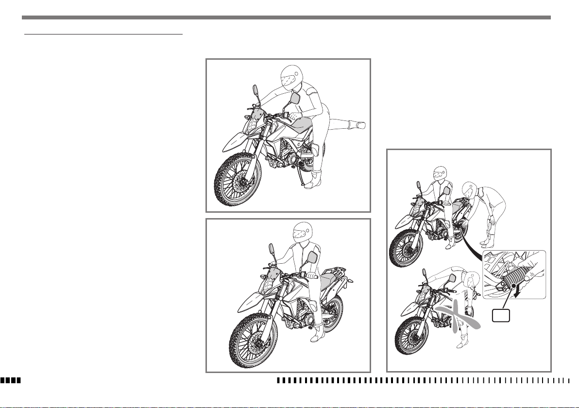
MOUNTING/DISMOUNTING OF RIDER AND PASSENGER
General
Read the following section carefully since it provides important information on the rider's and passenger's safety
and avoids causing damage to the motorcycle.
The motorcycle must always be mounted or dismounted
from the left-hand side with your hands free, no obstacles
in the way and with the stand down.
The rider must be the first to get on and the last to get
off the motorcycle and must control the stability of the
motorcycle while the passengers mounts and dismounts.
Do not get off the vehicle by jumping or extending your
legs and always dismount by following the instructions
given in the relevant section.
Mounting of rider
With the motorcycle on the side stand, do the following:
- From the left side, hold the handlebar correctly with
both hands and extend your right leg over the saddle.
- Sit on the motorcycle and place both feet on the
ground. Balance the vehicle without putting all your
weight on the side stand.
CAUTION*:
If you are unable to place both feet on
the ground, put your right leg down
with your left leg poised.
- Start the motorcycle as described in the relevant section.
- Using your left leg, fully retract the stand.
Mounting of passenger
Get the rider to mount first as described in the relevant
section without starting the engine.
- Get the passenger to put the passenger footrests (1)
down
CAUTION*:
When in a riding position, the rider
must not pull out or attempt to pull out
the rear passenger footrests since this
may unbalance the vehicle.
1
SPECIFICATIONS - OPERATION - MAINTENANCE
EN - 22
Page 25
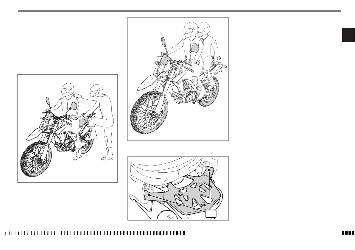
Place your left hand on the rider's shoulder, your left
foot on the footrest and then mount the motorcycle by
lifting your right leg and moving carefully to avoid
unbalancing the vehicle and the rider.
- Hold onto the special handles (2).
- Start the motorcycle as described in the relevant section
- Using your left leg, fully retract the stand.
Dismounting the motorcycle
- Stop the vehicle and switch off the engine.
CAUTION*:
Make sure that the area where you
want to park the vehicle is stable and
level.
- Place both feet on the ground.
- Using your left leg, fully extend the stand.
- Get the passenger to dismount first from the left-hand
side of the vehicle by placing their foot on the left-hand
footrest and raising their right leg.
- Tilt the motorcycle to the left until it rests on the stand.
- Switch off the motorcycle as described in the relevant
section
- Firmly grasp the handlebar and dismount on the lefthand side by lifting your right leg.
EN
2
SPECIFICATIONS - OPERATION - MAINTENANCE
EN - 23
Page 26
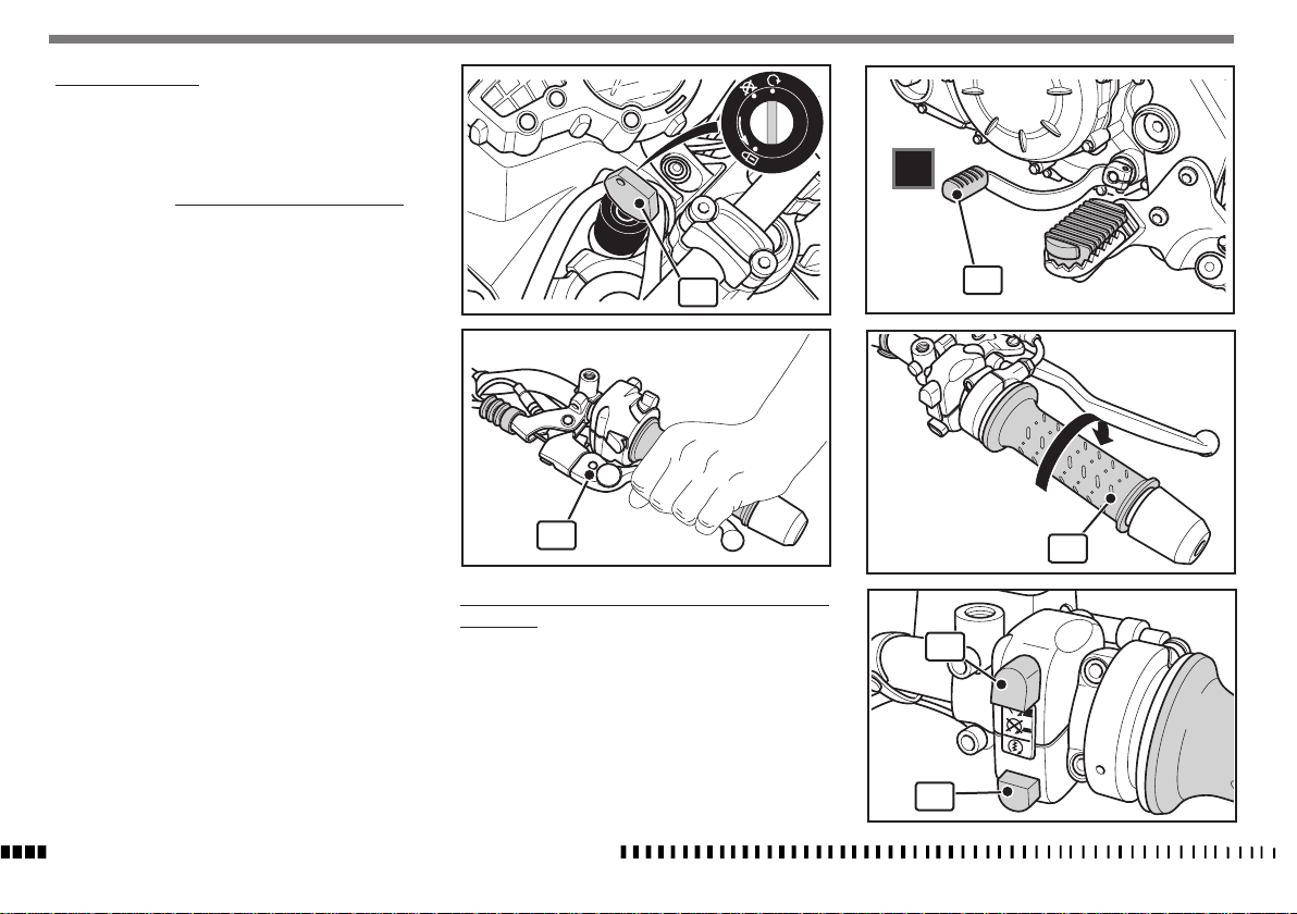
STARTING THE ENGINE
1) Turn key (1) in the ignition switch to ON and wait
until the dashboard CHECK has finished;
2) pull clutch lever (2);
3) shift gear pedal (3) to neutral;
4) check that the throttle control (4) is fully closed.
Note*:
The engine control unit has a start-
up strategy that only works if the
throttle control is fully closed.
5) Check that button (5) is in the out position and then
press the start button (6).
6) Release the clutch lever (2).
Note*:
A safety switch is mounted on the clutch lever support
that allows you to start the engine ONLY when the gearbox is in neutral or when the gear is engaged and the
clutch lever pulled.
ON
OFF
PUSH
N
1
3
There is a switch on the side stand that turns off the engine when the clutch is released with the gear engaged
and the side stand lowered.
IMPORTANT
NEVER START ENGINE WITH BATTERY DISCONNECTED FROM CIRCUIT.
SPECIFICATIONS - OPERATION - MAINTENANCE
EN - 24
2
IMPORTANT NOTE IN CASE OF COLD START AT LOW TEMPERATURES
We recommend idling for a short time to warm up the
engine.
This allows oil to reach all points that need lubricating
and coolant to warm up to regular operating temperature.
Avoid warming up the engine for too long.
4
5
6
Page 27
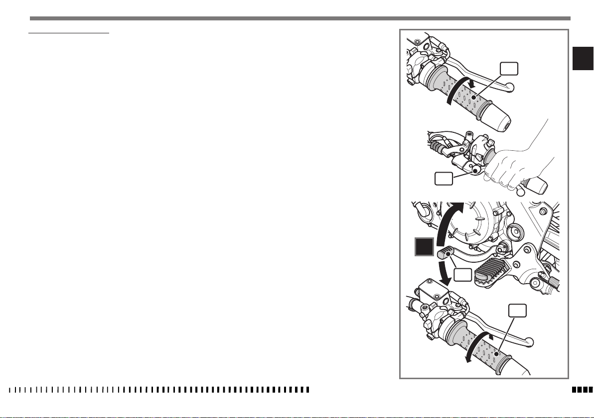
RIDING YOUR MOTORCYCLE
WARNING*:
Before setting off make sure that:
- the side stand is fully up;
- the rear footrests are closed if there
is no passenger;
- the passenger knows what to do
while riding to avoid problems when
manoeuvring.
1) Start the motorcycle as described in the relevant
section.
2) Adjust the rear-view mirrors to the riding position to
ensure correct visibility.
5) To go to the higher gears, do the following:
Release the throttle (1), pull the clutch lever (2),
lift the gear lever (3), release the clutch lever (2)
and accelerate at the same time.
1
EN
WARNING*:
Vehicles seen in the rear-view mirrors
appear to be further away than they
really are due to the special shape
of the rear-view mirrors; get familiar
with using your mirrors to ensure correct and safe riding.
3) With the throttle (1) closed and the engine idling,
pull the clutch lever (2) and push the gear lever (3)
down to select the first gear.
4) Slowly release the clutch lever (2) and, at the same
time, slightly accelerate by turning the throttle
twistgrip (1);
the vehicle will start to move.
Note*:
Select the best gear for the desired speed; speed changes
in proportion with turning the throttle. Therefore, turn
the throttle gradually without exceeding the recommended number of revs.
2
5
4
3
2
N
1
3
1
SPECIFICATIONS - OPERATION - MAINTENANCE
EN - 25
Page 28
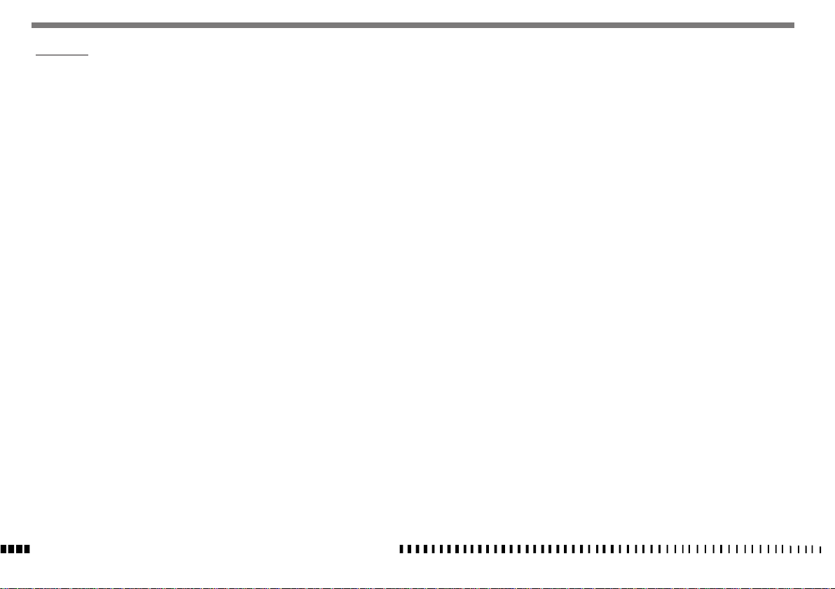
SAFE RIDING
Here are some basic principles for riding your motorcycle safely.
- Remember that your safety and the safety of your
passenger come first. Reaching your destination
safely must be your main aim.
- The rider and passenger must wear suitable protective clothing including overalls, gloves, shoes and a
helmet suitable for motorcyling.
- The rider must be seated on the motorcycle in a position that gives the best possible visibility of the road
ahead.
- Ride the motorcycle carefully and set the speed according to traffic and the type of road.
Smooth riding helps you to assess danger and enter
bends more precisely.
- Always observe road signs and adjust your speed accordingly.
- Always observe speed limits.
- Always assess the road conditions and adjust your
speed accordingly.
- Reduce speed if it is raining and especially if there
are puddles of water on the road.
- When riding on wet or low grip surfaces (snow, ice,
mud, etc.) keep a moderate speed and avoid sudden
braking and manoeuvres.
- Keep a safe distance from the vehicles in front of
you.
- Before overtaking, check there are no obstacles in
front of the vehicle you want to overtake and always
check in the rear-view mirrors that there are no vehicles coming up from behind.
- Brake using both the front and the rear brake at the
same time: this helps to maintain the stability of the
vehicle.
SPECIFICATIONS - OPERATION - MAINTENANCE
EN - 26
- Release the clutch gradually when downshifting.
- If you feel tired or sleepy, take a break.
- Downshift in the following instances:
When going downhill and when braking to increase
the braking action through engine compression; using only brakes when going downhill could cause
the brake pads to overheat and reduce the braking
action;
When going uphill or on the flat when the gear does
not match the speed of the motorcycle (high gear
and low speed);
WARNING*:
Downshift one gear at a time; down-
shifting more than one gear at a
time may cause the engine to overrev and/or block the rear wheel.
- Do not switch off the engine when going downhill.
- When you ride with a passenger, increase the distance from the vehicles in front of you and bar in
mind your weight when you brake and when you
have to round a bend or overtake.
- Do not use straps, cords, etc. to fasten luggage. Only
use approved panniers suitable for the type of motorcycle you are using.
Page 29
STOPPING THE MOTORCYCLE AND THE ENGINE
- Close the throttle (1) completely so that the engine
will help slow down the motorcycle.
- Apply both front (2) and rear (3) brakes while downshifting (for fast deceleration, press firmly on the
front brake lever and the rear brake pedal simultaneously).
- Pull the clutch lever (4), put the gear lever (5) into
neutral and then stop the motorcycle completely.
2
- To stop the engine, turn key (6) to OFF (key removal
position).
EN
ON
OFF
PUSH
3
6
WARNING*:
Independent use of the front or rear
brake may be advantageous under certain conditions. Be careful when using
the front brake, especially on slippery
4
surfaces. Improper use of the brakes
can lead to a serious crash.
N
5
1
SPECIFICATIONS - OPERATION - MAINTENANCE
EN - 27
Page 30
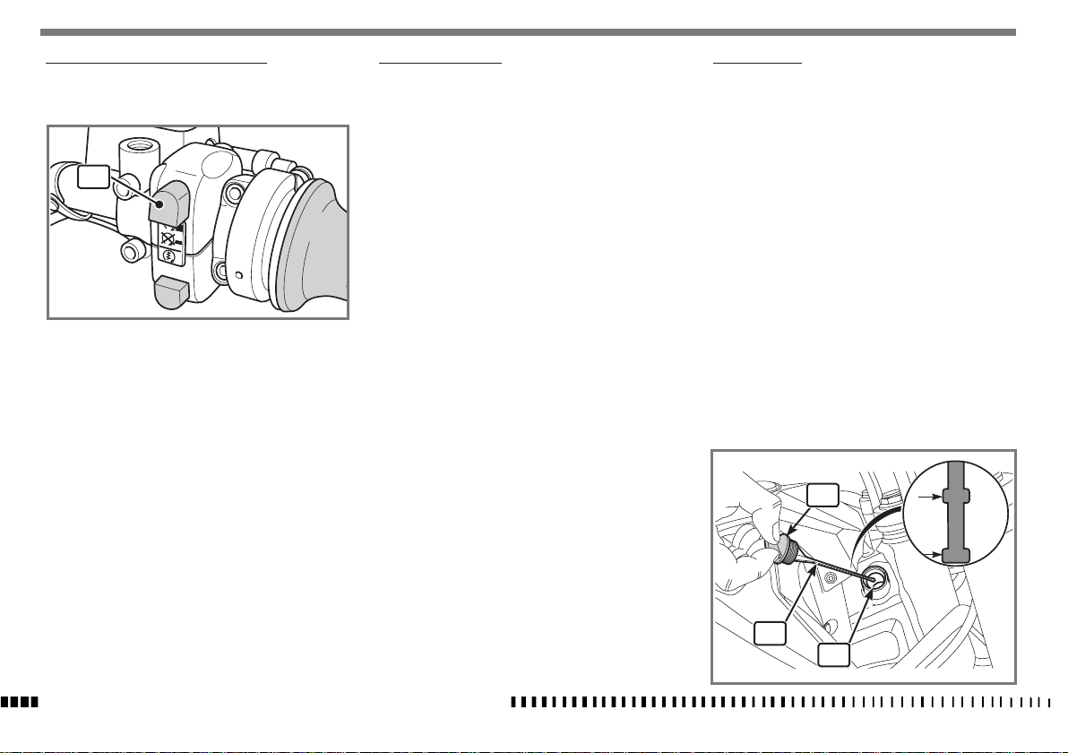
STOPPING THE ENGINE IN AN EMERGENCY
- In an “EMERGENCY” press the red button (1) to stop
the engine.
1
WARNING*:
Only use this button in an “EMERGENCY” and use it with extreme caution especially if the motorcycle is moving at
speed.
WARNING*:
In the event of a stuck throttle or other
malfunction that causes the engine to run
uncontrollably, pull the clutch lever IMMEDIATELY and press the engine stop switch.
Control the motorcycle by normal use of
the brakes and steering while holding the
engine stop button down.
CATALYTIC CONVERTER
- This motorcycle has an exhaust system with a catalytic converter; this oxidises the exhaust fumes (carbon monoxide and unburned hydrocarbons) and
converts them into carbon dioxide and water vapour.
CAUTION*:
The catalytic converter reaches very high
temperatures while the motorcycle is in
use. You should therefore avoid parking the motorcycle on dry grass because
there is a risk it will catch fire.
CAUTION*:
Do not tamper with and/or remove the
catalytic converter or its components;
removal of these components leads to
VEHICLE NON COMPLIANCE WITH TYPEAPPROVAL REQUIREMENTS making it unsuitable for use on public roads.
- Make sure there are no signs of rust or holes in the
exhaust system and that the exhaust system works
correctly; if the noise generated by the exhaust system increases significantly, contact an authorised
HUSQVARNA Dealer.
OIL LEVEL CHECK
The oil level must be checked with the vehicle in vertical
position on a flat surface.
- Start the motorcycle and heat the engine until the
cooling fan starts; wait for another 3 minutes and
switch off the engine.
- Check the level as follows:
- Undo the cap (1) with the dipstick (2) and remove
it from the frame.
- Clean the dipstick (2) with a cloth.
- Place the dipstick (2) in the hole (3) without
screwing the cap on.
- Remove the dipstick (2) from the hole (3) and
check that the level is between the two MIN and
MAX marks.
- To top up, pour oil into the hole (3); for the type of
oil, see the section “Technical data”.
CAUTION*:
Never exceed max. level.
MAX
MIN
MAX
MIN
1
SPECIFICATIONS - OPERATION - MAINTENANCE
EN - 28
2
3
Page 31
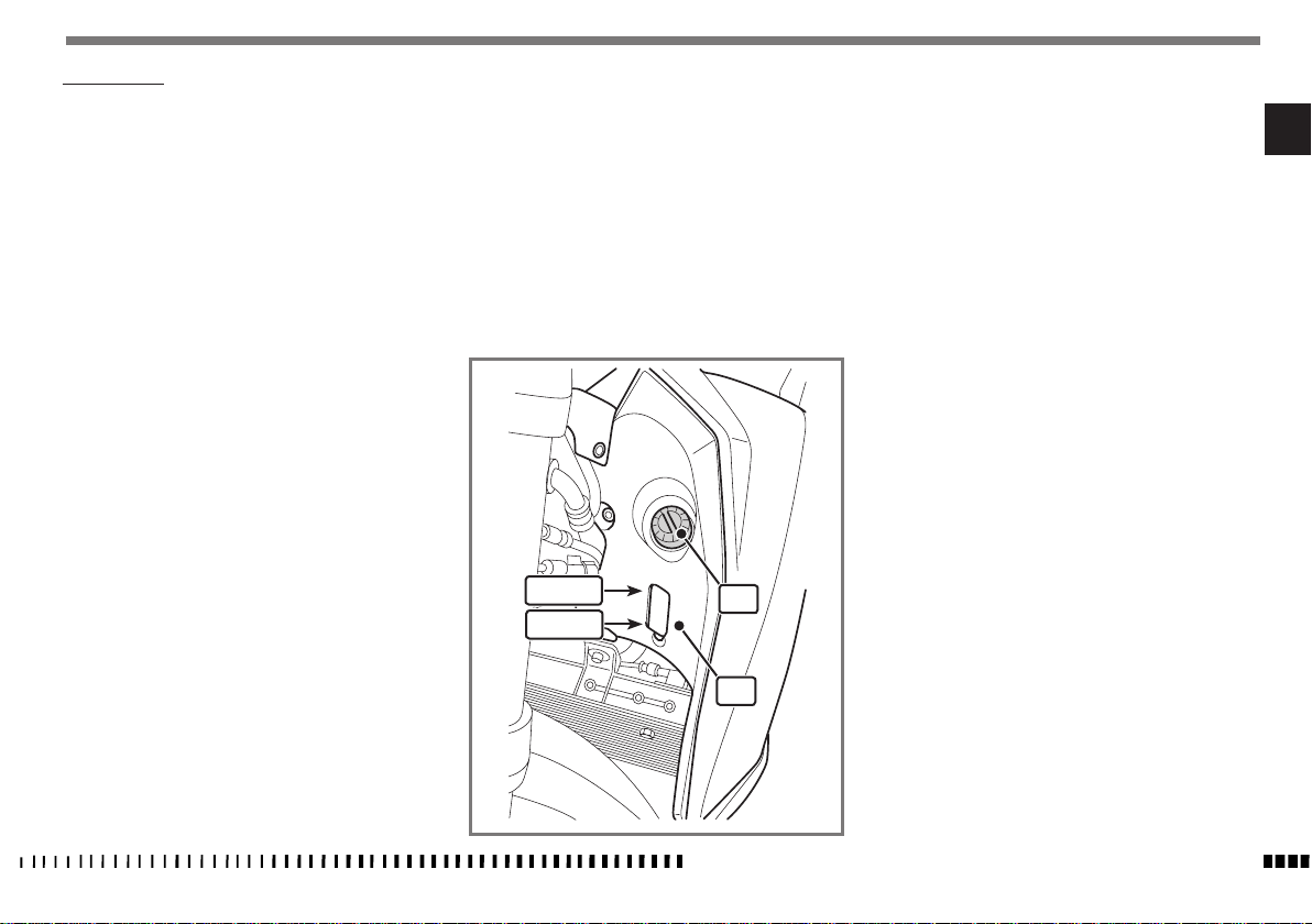
COOLANT LEVEL
When the engine is cold, check that the coolant level is
between the two MIN and MAX marks on the expansion tank (1) on the left side of the vehicle.
If topping up is necessary, do the following:
WARNING
Do not remove the radiator cap since
all the liquid in the expansion tank
(1) will flow out.
- Remove the cap (2) and add the fluid needed to restore the level to the expansion tank (1).
( for the type of liquid to use, see the section “Tech-
nical data”.
Note*:
Difficulties may arise in eliminating coolant from painted
surfaces. If this occurs, wash off with water.
CAUTION*:
Never exceed max. level.
MAX
MIN
EN
2
1
SPECIFICATIONS - OPERATION - MAINTENANCE
EN - 29
Page 32
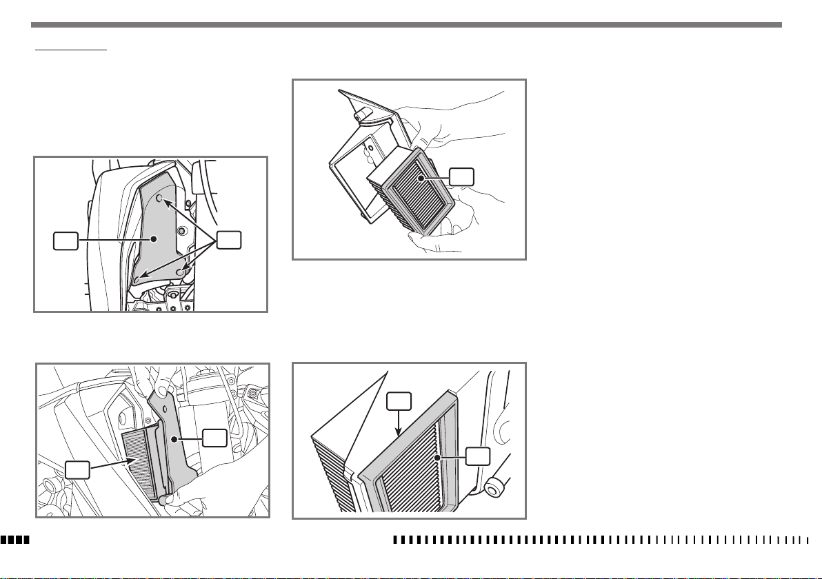
AIR FILTER CHECK
Note*:
Clean the filter area before removing the cover.
- Loosen the screws (1) and remove the cover (2) complete with filter (3);
- remove the filter (3) and make sure it is not
blocked/dirty; if necessary, change it;
3
CAUTION*:
Before refitting the filter, check that the
contact surfaces between the filter, the
filter box and the cover are completely
clean.
2
1
- when fitting back on, make sure the filter (3) is
2
3
SPECIFICATIONS - OPERATION - MAINTENANCE
EN - 30
properly fitted in its housing (4).
4
3
Page 33
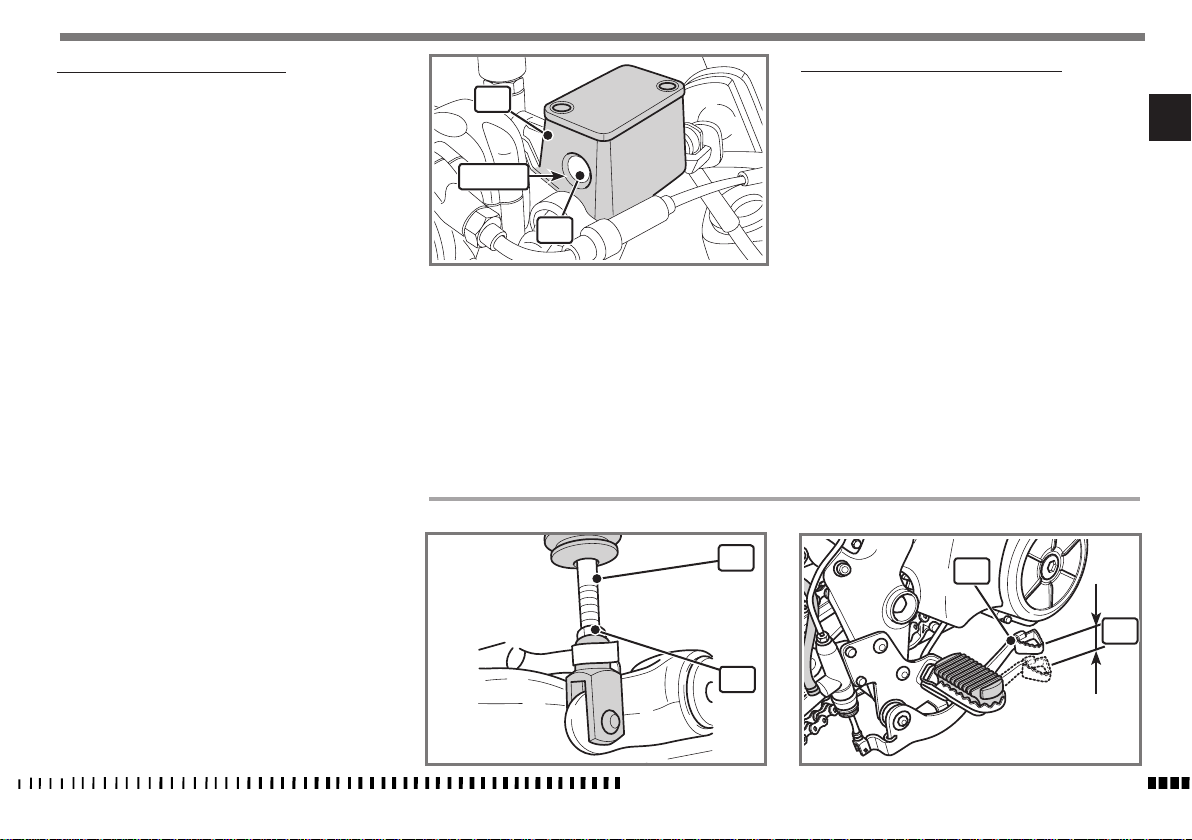
CHECK THE FRONT BRAKE FLUID LEVEL
The level of the fluid in the master cylinder reservoir
must never be below the minimum level visible through
the inspection sight glass (1) on the side of the master
cylinder (2) body.
A decrease of the fuel level will let air into the sustem, hence an
extension of the level stroke.
WARNING*:
If the brake lever feels mushy when
pulled, there may be air in the brake
lines or the brake may be defective.
Since it is dangerous to operate the motorcycle under such conditions, have the
brake system immediately checked by
the Husqvarna Dealer.
CAUTION*:
Do not spill brake fluid onto any painted surface or lenses (for example lights
lenses).
CAUTION*:
Do not mix two brands of fluid. Completely change the brake fluid in the
brake system if you wish to switch to
another fluid brand.
2
MIN
REAR BRAKE PEDAL FREE PLAY ADJUSTMENT
Before starting braking action, the rear brake control
pedal (1) must have free play (B) of 5-10 mm (0.196
- 0.39 in).
EN
Should this not happen, operate as follows:
- Loosen the nut (2);
- Operate the master cylinder linkage (3) to increase or
decrease free play;
1
- tighten nut (2) at the end of the operation.
WARNING*:
When the free play requirement is not
met, the brake pads will be subjected
to an early wear that may lead to TOTAL
BRAKE INEFFECTIVENESS.
3
1
CAUTION*:
Brake fluid may cause irritation. Avoid
contact with skin or eyes. In case of contact, flush thoroughly with water and
call a doctor if your eyes were exposed.
2
SPECIFICATIONS - OPERATION - MAINTENANCE
B
EN - 31
Page 34
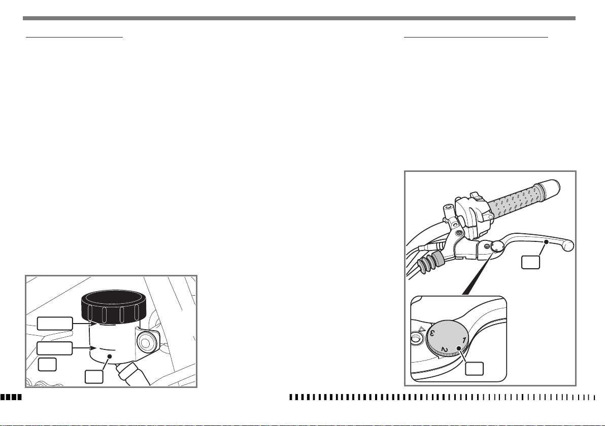
REAR BRAKE FLUID LEVEL CHECK
The fluid level in the master cylinder tank shall never be
below the minimum level (1) shown on the transparent
reservoir (2).
A decrease in the fluid level will let air into the system
and increase the lever stroke.
WARNING*:
If the brake pedal feels mushy when
pulled, there may be air in the brake
lines or the brake may be defective.
Since it is dangerous to operate the motorcycle under such conditions, have the
brake system immediately checked by
the Husqvarna Dealer.
CAUTION*:
Do not spill brake fluid onto any painted surface or light lens.
CAUTION*:
Do not mix two brands of fluid. Completely change the brake fluid in the
brake system if you wish to switch to
MAX
another fluid brand.
CAUTION*:
Brake fluid may cause irritation. Avoid
contact with skin or eyes. In case of contact, flush thoroughly with water and
call a doctor if your eyes were exposed.
CLUTCH CONTROL LEVER DISTANCE ADJUSTMENT
The lever (1) can be adjusted (3 settings available) to
suit the rider's hand size
To regulate the position of the lever (1) push it outwards
and then select the required position by means of the
adjuster screw (2).
1
MIN
1
2
SPECIFICATIONS - OPERATION - MAINTENANCE
EN - 32
2
Page 35
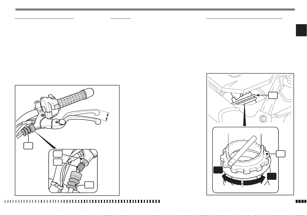
CLUTCH LEVER FREE PLAY ADJUSTMENT
Free play (A) must be 5 -10 mm (0.196 - 0.39 in).
- Move the rubber gaiter (1);
- regulate the adjuster screws (2) and the counter adjuster screw (3) to obtain the indicated free play.
- after completing the operation, make sure the counter
adjuster screw (3) is properly tightened and then replace the rubber gaiter (1).
1
3
2
1
SUSPENSION
The vehicle leaves the factory with standard settings for
the front and rear suspension that meet most requirements.
The front fork cannot be regulated in any way. On the
rear shock absorber, the spring preload and the rebound
hydraulic damping can be regulated.
A
SHOCK ABSORBER SPRING PRELOAD ADJUSTMENT
- Adjust the ring nut (1) using the spanner provided; by
turning left “A”, the preload increases;
by turning right “B” the preload decreases.
WARNING*: Be careful not to touch hot
exhaust pipe while adjusting the shock
absorber.
1
1
A
B
EN
SPECIFICATIONS - OPERATION - MAINTENANCE
EN - 33
Page 36
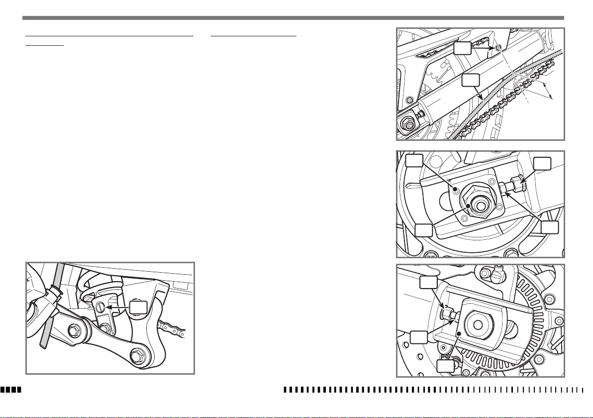
REBOUND SHOCK ABSORBER HYDRAULIC DAMPING
ADJUSTMENT
It is possible to adjust the rebound travel of the shock
absorber.
B) REBOUND - Standard setting:
- 11 clicks
(adjuster 1)
To reset the standard setting, turn lower adjuster (1)
clockwise until reaching fully closed position. Then turn it
back the number of clicks specified above.
In order to obtain a smooth braking action, turn the adjuster counter clockwise. Vice versa to obtain a harder
braking action.
1
CHAIN TENSION ADJUSTMENT
Chain should be checked, adjusted and lubricated as per
the Maintenance Chart to ensure safety and prevent excessive wear.
If the chain becomes badly worn or is adjusted incorrectly
(i.e., it is too loose or too tight), it could jump out of the
sprocket or break.
- Position the motorcycle on the side stand so the chain is
not stressed and loaded;
- where the screw (1) is located, lift the chain (2) upwards and measure the chain travel.
- the correct setting must be 45 mm (1.77 in).
If this is not the case, proceed as follows:
- make sure that the motorcycle is fully upright on the
special rear support stand (optional).
- on the right side, loosen the locking nut (3) of the
wheel axle;
- loosen the check nuts (4) on both chain tensioners;
- turn the adjuster screws (5) to obtain the correct tension and check on both sides that the wheel centring
sliders (6) are in the same position as the markings in
the chain tensioner slider seats on the swinging arms;
- once adjusted, tighten the check nuts (4) and the wheel
axle nut (3).
After adjusting, always check that distance "A" is 45
mm (1.77 in).
1
2
A
45 mm
6
3
4
4
5
SPECIFICATIONS - OPERATION - MAINTENANCE
EN - 34
5
6
Page 37
CHECKING CHAIN AND SPROCKETS FOR WEAR
Check that the chain does not have damaged rollers,
loose pins or dry, rusty links and is not excessively worn.
Check that the front and/or rear sprocket are not excessively worn and do not have missing teeth.
If replaced, the sprockets and chain must be replaced at
the same time.
LUBRICATING THE CHAIN
Lubricate the chain following these instructions.
CAUTION*:
Never use grease to lubricate the chain.
Grease helps to accumulate dust and
mud, which act as abrasive and help
to rapidly wear out the chain, the front
and rear sprockets.
CAUTION*:
Do not wash the chain with high-pressure water jets and do not use harsh or
highly flammable solvents.
- After washing the chain using special detergent, dry it
and lubricate with suitable spray grease.
CAUTION*:
The chain lubricant must NOT come into
contact with the tyres or the rear brake
disc.
TYRES
Care should be taken to keep the tyres properly inflated.
See "Technical data" chart at the beginning of the manual for correct tyre inflation pressure.
Tyre pressure must be measured when the tyres are cold.
Warm tyres will give an incorrect reading.
WARNING*:
The correct pressure and correct state of
the tyres not only enhances riding comfort but also avoids loss of grip on the
road with loss of balance and possible
falls.
If tyres are old but not completely worn,
they must be replaced because they
harden and do not guarantee the correct grip.
ABS SYSTEM
The ABS is an electromechanical braking-aid system:
it prevents the wheels from locking during braking and
helps keep the vehicle stable whenever the road surface
is slippery, wet or dirty.
When road-holding conditions are bad, the system can
operate to extend the braking distance (e.g., whenever
there is gravel on the road or the road surface is slippery). In any case, it provides the minimum distance
required for that particular road surface.
When the system operates during braking, pulsations are
felt on the brake lever: this feeling should not cause the
rider to reduce pressure on the lever, as this would cancel
out the action of the system.
Nor should the fact that an ABS system is fitted provoke
careless riding. The rider should always take every care
on the road.
EN
SPECIFICATIONS - OPERATION - MAINTENANCE
EN - 35
Page 38
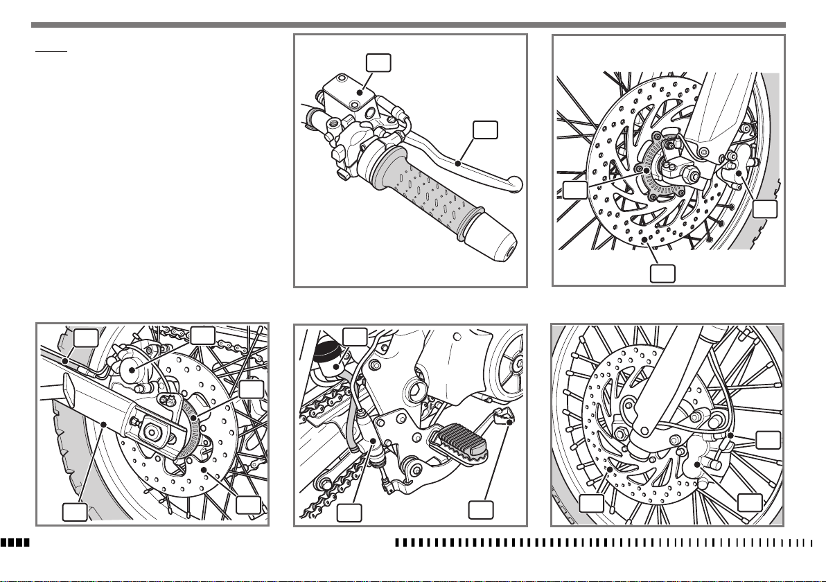
BRAKES
The key components of the braking systems are: brake
master cylinder with its lever (front) or pedal (rear),
brake lines, calliper assembly and disc.
2
LEGEND
Front brake control lever
1.
2. Front brake master cylinder with fluid reservoir
3. Front brake line
Right-hand front brake calliper
4.
5. Right-hand front brake disc
6. Rear brake fluid reservoir
7. Rear brake line
Rear brake calliper
8.
9. Rear brake disc
10. Rear brake master cylinder
11. Rear brake control pedal
12. Front phonic wheel (ABS version)
13. Rear phonic wheel
7
11
8
13
9
10
1
12
4
5
6
3
11
5
4
SPECIFICATIONS - OPERATION - MAINTENANCE
EN - 36
Page 39
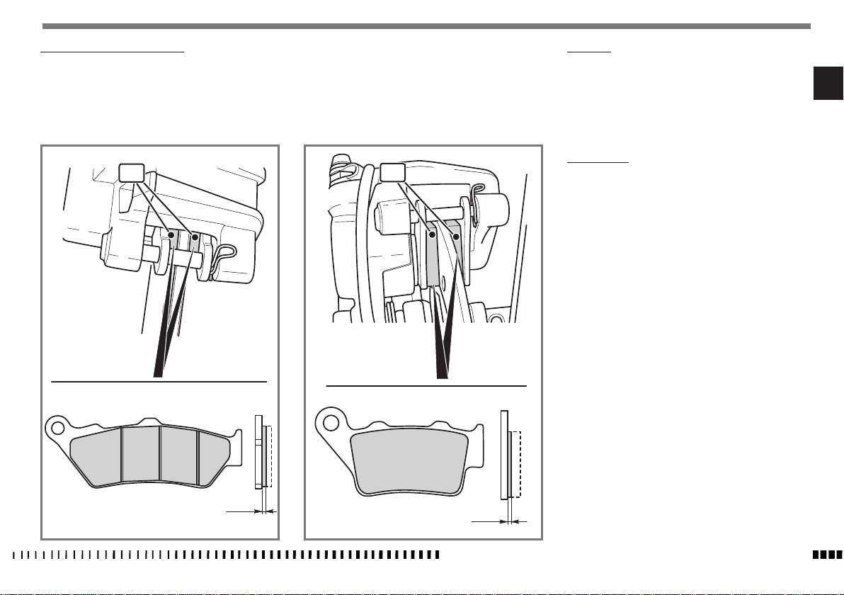
CHECKING BRAKE PADS FOR WEAR
Checking front brake calliper pads.
- Place the motorcycle on the stand.
- Visually inspect the state of the brake pads (1) from the
rear of the calliper;
1
Checking rear brake calliper pads.
- Visually inspect the state of the brake pads (2) from the
rear of the calliper;
2
PAD WEAR
Check brake pad wear.
Service limit “ A” is: 1 mm (0.04 in).
If this limit has been exceeded or even if one of the wear
indicators is no longer visible, replace both brake pads.
PAD CLEANING
Be careful that no brake fluid or any oil gets on brake
pads or discs. Clean off with alcohol any fluid or oil that
inadvertently gets on the pads or disc. Replace the pads
with new ones if they cannot be cleaned satisfactorily.
EN
A = 1 mm
A = 1 mm
SPECIFICATIONS - OPERATION - MAINTENANCE
EN - 37
Page 40
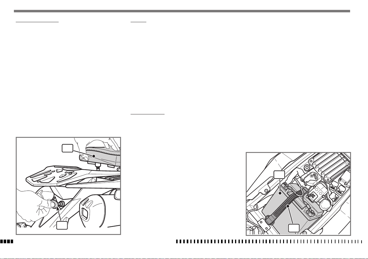
REMOVING THE SADDLE
To remove the saddle proceed as follows:
- Insert the key in the lock (1) positioned in the rear
part of the motorcycle;
- turn the key clockwise to release the saddle (2), and
then lift it and pull it out towards the rear, releasing it
from the front fastener.
To fit the saddle back on, fasten it at the front and then
press the rear until the fastening "Click" is heard.
2
1
SPECIFICATIONS - OPERATION - MAINTENANCE
EN - 38
BATTERY
The sealed battery does not require any maintenance.
When electrolyte leaks, or other failure of the electrical
system is detected, apply to the HUSQVARNA Dealer.
If the vehicle remains unused for long periods, it is recommended to disconnect the battery from the electrical
system and store it in a dry place.
- After extensive use, battery should be allowed to run
a slow charging cycle
1A for 10 hours for 12V-10Ah battery.
- Battery quick charging is only recommended under
extremely urgent conditions, as lead elements life
will be greatly reduced.
6A for 1 hour for 12V-10Ah battery.
BATTERY CHARGER
To gain access to the battery:
- Make sure that the ignition switch has been turned to
OFF and that the key has been removed;
- remove the saddle as described in the specic paragraph;
- rst remove the BLACK or BLUE negative cable, then
the RED positive cable (when reassembling, rst con-
nect the RED positive cable, then the BLACK or BLUE
negative cable);
- release the elastic (1);
- remove the battery (2) from its housing.
Check, using a voltmeter, that battery voltage is not less
than 12.5 V.
If it is not so, the battery needs to be charged.
Using a battery charger with a constant voltage, first connect the RED positive cable to the battery positive terminal then the BLACK or BLUE negative cable to the battery
negative terminal.
The voltage reaches a constant value only after a few
hours, therefore it is suggested NOT to measure it immediately after having charged or discharged the battery.
Always check the battery charge before reinstalling it on
the vehicle.
The battery should be kept clean and the terminals
coated with neutral grease or petroleum jelly.
CAUTION*:
Even if not used, the battery shall be
recharged with a slow charging cycle at
least every 3 weeks.
WARNING*:
When removing the battery, avoid all
contact between the battery terminals
and the metal parts of the vehicle (e.g.
chassis) to prevent short-circuiting.
2
1
Page 41
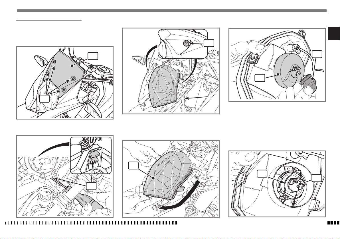
FRONT HEADLAMP BULB REPLACEMENT
Proceed as follows to reach the headlamp bulbs:
- Loosen the screws (1) and remove the front fairing (2);
- loosen the two side headlight retention screws (4);
- disconnect the connector (6);
EN
4
2
1
- completely loosen the top headlight adjustment screw
(3);
3
- remove the headlight (5) by turning it downwards (see
illustration);
5
6
7
- remove the rubber hood(7), release the retainer clip (8)
and remove the light bulb (9);
Note*:
Headlamp bulb (9) is of the halogen type; be careful when replacing it since the glass part shall not be
touched with bare hands.
8
9
SPECIFICATIONS - OPERATION - MAINTENANCE
EN - 39
Page 42
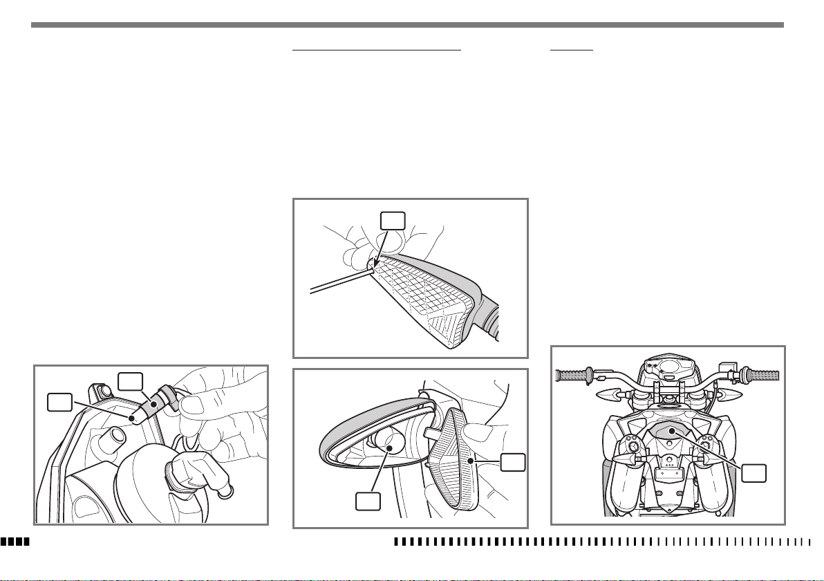
To replace the parking light bulb:
-
Detach the bulb holder (10) and remove the light bulb (11).
After making replacement, proceed to fit back on in the
reverse sequence and then regulate the light beam as
described in the specific paragraph.
10
11
TURNING INDICATOR BULB REPLACEMENT
- Loosen screw (1) using a Phillips screwdriver;
- remove lens (2) and replace bulb (3) pushing it inside,
and turning it to remove it;
Once the bulb has been replaced, reverse the above procedure to reassemble.
1
TAIL LIGHT
The tail light (1) is a LED light; if it does not work properly, it must be replaced.
SPECIFICATIONS - OPERATION - MAINTENANCE
EN - 40
2
3
1
Page 43
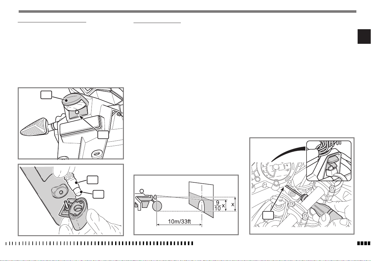
REPLACING THE NUMBER PLATE BULB
HEADLIGHT ADJUSTMENT
Beam height can be adjusted as follows:
- loosen screw (1) and remove the number plate bulb
(2) from the mudguard;
- take bulb holder (3) and bulb (4) out of the support;
- pull the bulb (4) to detach it from bulb holder.
Once the bulb has been replaced, reverse the above procedure to reassemble.
2
1
3
4
When checking the proper aiming of the headlight beam:
inflate tyres at the right pressure, have a person sit
astride the motorcycle and set the motorcycle perpendicular to its longitudinal axis
In front of a wall or a screen positioned at a distance of
10 metres (32.8 ft), draw a horizontal line corresponding to headlight centre height, and a vertical line aligned
with vehicle longitudinal axis.
If possible, execute this operation in a shaded place.
When the low beam is on, the upper edge between dark
and lit zone should be at 9/10th of headlight centre from
ground.
- Regulate the setscrew (1) on the upper part of the light
unit;
by tightening, the light beam is raised;
by loosening, the light beam is lowered.
EN
1
SPECIFICATIONS - OPERATION - MAINTENANCE
EN - 41
Page 44
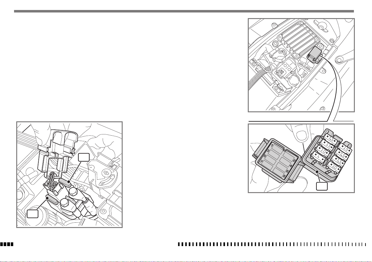
FUSES
Please note that a fuse malfunction can adversely affect
motorcycle operation. To gain access to fuses, proceed
as follows:
General fuse (1) - 30A
Two fuses positioned in the rear part of the motorcycle
on the solenoid starter, one of which is spare.
1= General fuse.
2= Spare fuse.
1
2
Auxiliary fuses (3)
Located at the rear of the motorcycle under the saddle.
Fuse 1 = 7.5 A
Instrument panel
Turning indicators
Engine control
Solenoid starter
Diagnosis socket
Fuse 2 = 15 A
Horn
Number plate light
Headlight (high beam and low beam)
Stop light
Accessories socket
Fuse 3 = 15 A
Ignition
Injectors
Fuel pump
Fuse 4 = 7.5 A
Lambda sensor
Canister washing valve
Fuse 5 = 10 A
Radiator fan
Fuse 6 = 7.5 A
Instrument panel
Antitheft
Diagnosis socket
Fuse 7 = 4 A
Parking lights
ABS (where fitted)
Fuse 8 = 10 A
Engine control
3
• Never replace a fuse with another
fuse with a different rating.
To avoid possible short circuits, set the ignition switch to
OFF before servicing the fuses.
SPECIFICATIONS - OPERATION - MAINTENANCE
EN - 42
Page 45
APPENDIX
LONG PERIOD OF INACTIVITY
When the motorcycle is to be stored for a certain period,
it should be prepared for storage as follows:
- clean the entire motorcycle thoroughly.
- Drain all fuel from the tank.
- Fill the tank with fuel added with a stabiliser
WARNING*:
Never release fuel into the environment
or let the engine run indoors.
- Lubricate the final drive chain and all the cables.
- Spray oil on all unpainted metal surfaces to prevent
rusting. Avoid getting oil on rubber parts or brakes.
- Set the motorcycle on a support or stand so that both
wheels are raised off the ground (if this cannot be
done, put boards under the wheels to keep moisture
away from the tyres).
- Tie a plastic bag over the exhaust pipe to prevent moisture from entering.
- Put a cover over the motorcycle to keep dust and dirt
from collecting on it.
To set the motorcycle back ready for use after storage:
- Fill the fuel tank.
- Check all the points listed under the inspection and
Adjustment Section (Appendix A).
- Lubricate all the points listed under the "Lubrication"
Section (Appendix A).
CLEANING
Cleaning the vehicle is very important especially if it is
used in special areas or conditions such as:
- coastal areas with a high salt level;
- winter periods in areas where de-icing chemicals and/or
salt are used on the roads;
- areas where resinous plants grow;
- especially dusty areas.
Make sure that all dead insects, tar spots, bird droppings,
etc. are removed from the bodywork.
CAUTION*:
Before washing the motorcycle:
- the engine must be cold;
- you must carefully protect the following
parts from water by covering the openings with cloths or plastic bags:
1) Rear exhaust opening;
2) Air box air intake.
3) Sensitive electrical/electronic com-
ponents.
- Wash the motorcycle with a low-pressure water jet to remove any dust and mud. The bodywork must be cleaned
with a soft sponge and a water and bodywork shampoo
solution.
- After cleaning, rinse thoroughly with low pressure running water.
3
2
1
EN
SPECIFICATIONS - OPERATION - MAINTENANCE
EN - 43
Page 46
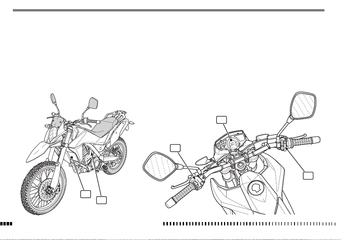
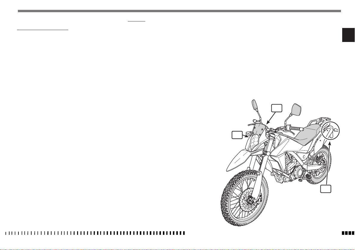
CAUTION*:
AVOID USING HIGH-PRESSURE WATER OR
AIR JETS on the ELECTRICAL COMPONENTS
and on the FUEL INJECTION SYSTEM, the
dashboard (3), the radiator (4), the
throttle body (5) and switches (6) and
(7).
- Wash the saddle with mild, non-aggressive detergent and
dry thoroughly after washing.
After washing:
- Lubricate the drive chain, the lever and pedal controls
and the clutch cable.
- Briefly warm up the engine.
WARNING*:
Never wax or lubricate the brake discs
since this could lead to a loss of braking
efficiency and could cause an accident.
Clean the disc with a solvent such as acetone.
6
After washing, braking efficiency could
be temporarily reduced due to the presence of water on the friction surfaces of
the brake discs and pads. You should
therefore calculate a longer braking distance and repeatedly use the brakes until the friction surfaces have completely
dried.
3
7
4
5
SPECIFICATIONS - OPERATION - MAINTENANCE
EN - 44
Page 47
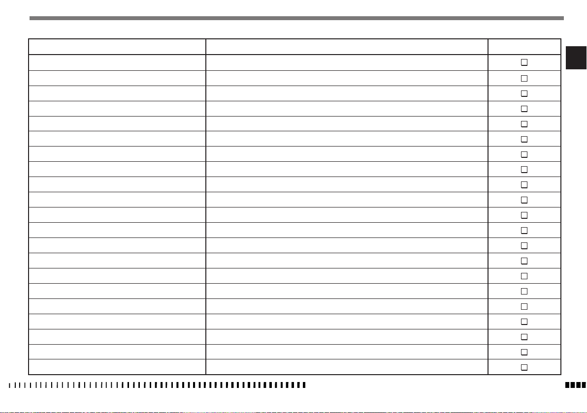
PRE - DELIVERY INSPECTION
DESCRIPTION OPERATION PRE-DELIVERY
Engine oil Check level
Coolant Check
Cooling system Check for leakage
Electric fans Check operation
Brakes fluid Check level
Brakes Check operation
Throttle control Check operation / Clearance
Flexible controls and transm. Check / Adjust
Drive chain Check / Adjust
Tyres Check pressure
Side stand Check operation
Side stand switch Check operation
Instrument panel Check operation
Lights / Visual signals Check operation
Horn Check operation
Headlight Check operation / Adjust
Ignition switch Check operation
Safety switches Check operation
Battery Fully charge
Side stand Check freedom of movement
General test
EN
SPECIFICATIONS - OPERATION - MAINTENANCE
EN - 45
Page 48
ALPHABETIC INDEX
Page
A
...................................................................................35
ABS SYSTEM
AIR FILTER CHECK
APPENDIX
B
BATTERY
BATTERY CHARGER
BRAKES
C
CATALYTIC CONVERTER
CHAIN TENSION ADJUSTMENT
CHECKING BRAKE PADS FOR WEAR
CHECKING CHAIN AND SPROCKETS FOR WEAR
CHECK THE FRONT BRAKE FLUID LEVEL
CLEANING
CLOCK ADJUSTMENT
CLUTCH CONTROL
CLUTCH CONTROL LEVER DISTANCE ADJUSTMENT
CLUTCH LEVER FREE PLAY ADJUSTMENT
COMBINED DASHBOARD..................................................................13
CONTROLS
COOLANT LEVEL
D
DESCRIPTION OF MULTIFUNCTION DISPLAY
DESCRIPTION OF WARNING LIGHTS
F
FRONT BRAKE CONTROL
FRONT HEADLAMP BULB REPLACEMENT
FUSES
G
GEAR SHIFT CONTROL
H
HEADLIGHT ADJUSTMENT ...............................................................41
EN - 46
...........................................................................30
.......................................................................................43
.........................................................................................38
..........................................................................38
..........................................................................................36
...................................................................28
..........................................................34
..................................................37
..................................35
...........................................31
.......................................................................................43
.......................................................................15
...........................................................................19
.............................32
...........................................33
......................................................................................12
..............................................................................29
......................................14
.................................................14
..................................................................17
...........................................39
............................................................................................42
.....................................................................19
SPECIFICATIONS - OPERATION - MAINTENANCE
I
IDENTIFICATION DATA
IGNITION SWITCH
IMPORTANT NOTICES.........................................................................3
INSTRUCTIONS FOR USING THE MOTORCYCLE
L
LONG PERIOD OF INACTIVITY
L.H. HANDLEBAR SWITCH
LUBRICATING THE CHAIN
M
MOTORCYCLE OVERALL VIEW
MOUNTING/DISMOUNTING OF RIDER AND PASSENGER
O
OIL LEVEL CHECK
P
PAD CLEANING
PAD WEAR
PRE - DELIVERY INSPECTION
PRE-RIDE CHECKS
PRESENTATION
R
REAR BRAKE CONTROL
REAR BRAKE FLUID LEVEL CHECK
REAR BRAKE PEDAL FREE PLAY ADJUSTMENT
REBOUND SHOCK ABSORBER HYDRAULIC DAMPING ADJUSTMENT
REFUELLING
REMOVING THE SADDLE
REPLACING THE NUMBER PLATE BULB
RIDING YOUR MOTORCYCLE
RIGHT-HAND HANDLEBAR SWITCH
S
SAFE RIDING
SETTING PARAMETERS
SETTING UNITS OF MEASUREMENT
SHOCK ABSORBER SPRING PRELOAD ADJUSTMENT
SIDE STAND
STARTING THE ENGINE
.......................................................................7
...........................................................................17
...................................20
..........................................................43
................................................................18
.................................................................35
...........................................................10
...................22
............................................................................28
...............................................................................37
......................................................................................37
............................................................45
...........................................................................20
.................................................................................3
....................................................................19
.....................................................32
...................................31
....34
...................................................................................12
..................................................................38
..............................................41
............................................................25
..................................................18
..................................................................................26
.....................................................................16
...................................................15
...........................33
....................................................................................12
....................................................................24
STEERING LOCK
STOPPING THE ENGINE IN AN EMERGENCY
STOPPING THE MOTORCYCLE AND THE ENGINE
SUMMARY
SUSPENSION
T
TAIL LIGHT
TECHNICAL DATA ...............................................................................8
THROTTLE CONTROL
TROUBLESHOOTING
TURNING INDICATOR BULB REPLACEMENT........................................40
TYRES.............................................................................................35
..............................................................................18
.......................................28
.................................27
........................................................................................2
.................................................................................33
......................................................................................40
........................................................................17
........................................................................21
 Loading...