


 Loading...
Hp PROLIANT ML150 G2, PROLIANT ML310 G4, PROLIANT ML330 G2, PROLIANT ML350 G2, PROLIANT DL145 Fully-Buffered DIMM technology
...Fully-Buffered DIMM technology in HP ProLiant servers
technology brief
Abstract.............................................................................................................................................. |
2 |
Introduction......................................................................................................................................... |
2 |
Performance barriers for traditional DIMM.............................................................................................. |
2 |
Fully-Buffered DIMM architecture ........................................................................................................... |
4 |
Benefits........................................................................................................................................... |
6 |
Simplified board design ................................................................................................................ |
6 |
Higher memory capacity ............................................................................................................... |
6 |
Higher performance...................................................................................................................... |
7 |
Improved reliability....................................................................................................................... |
7 |
Challenges...................................................................................................................................... |
8 |
Latency ....................................................................................................................................... |
8 |
Power and thermal loads............................................................................................................... |
8 |
Performance tuning, achieving maximum performance ............................................................................. |
9 |
Conclusion.......................................................................................................................................... |
9 |
For more information.......................................................................................................................... |
10 |
Call to action .................................................................................................................................... |
10 |
Abstract
This paper describes the features, benefits, and challenges of Fully-Buffered dual inline memory module (FB-DIMM) technology. It also provides rules for populating FB-DIMM slots to achieve maximum performance in HP ProLiant servers.
Introduction
HP ProLiant servers provide balanced system architectures that deliver peak performance per watt of power. A balanced system architecture is one in which the three main server subsystems—processing, memory, and I/O—interact efficiently to maximize CPU performance. The introduction of dual-core processor technology challenged HP engineers to improve the performance of the memory and I/O subsystems to maintain system balance. Engineers overcame the performance bottleneck of the parallel I/O bus by migrating to a high-speed serial interface with technologies such as SerialAttached SCSI, Serial ATA, and PCI Express. Likewise, some memory subsystems are migrating to high-speed serial FB-DIMM technology to deliver scalable bandwidth and memory capacity that is not possible with traditional DIMM technologies.
The paper describes the barriers that limit memory capacity and performance of servers that use traditional DIMM technologies. This paper also describes the operation of FB-DIMMs and summarizes the benefits and challenges of using FB-DIMM technology.
Performance barriers for traditional DIMM
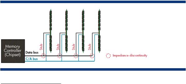
Traditional DIMM architectures use a stub-bus topology with parallel branches (stubs) that connect to a shared memory bus (Figure 1). The memory bus consists of the command/address (C/A) bus and the data bus. The C/A bus consists of 21 data traces that transport command and address signals to the DIMMs. The data bus consists of 72 traces, each carrying one bit at a time (a total of 64 data bits and 8 ECC1 bits). Each DIMM connects to the data bus using a set of pin connectors2. In order for the electrical signals from the memory controller to reach the DIMM bus-pin connections at the same time, all the traces have to be the same length. This often results in circuitous traces on the motherboard between the memory controller and memory slots. Both the latency (delay) resulting from complex routing of traces and signal degradation at the bus-pin connections cause the error rate to increase as the bus speed increases.
Figure 1. Stub-bus topology. An impedance discontinuity is created at each stub-bus connection.
1Error correcting code
2Typical SDRAM DIMMs have a total of 168 pins, DDR DIMMs have 184 pins, and DDR2 DIMMs have 240 pins.
2

Each stub-bus connection creates an impedance discontinuity that negatively affects signal integrity. In addition, each DIMM creates an electrical load on the bus. The electrical load accumulates as DIMMs are added. These factors decrease the number DIMMs per channel that can be supported as the bus speed increases. For example, Figure 2 shows the number of loads supported per channel at data rates ranging from PC 100 to DDR-3 1600. Note that the number of supported loads drops from eight to two as data rates increase to DDR2 800.
Increasing the number of channels to compensate for the drop in capacity per channel was not a viable option due to increased cost and board complexity. System designers had two options: limit memory capacity so that fewer errors occur at higher speeds, or use slower bus speeds and increase the DRAM density. For future generations of high-performance servers, neither option was acceptable.
Future generations of servers require an improved memory architecture to achieve higher memory bandwidth and capacity. Consequently, JEDEC3 developed the Fully-Buffered DIMM specification, a serial interface that eliminates the parallel stub-bus topology and allows higher memory bandwidth while maintaining or increasing memory capacity.
Figure 2. Maximum number of loads per channel based on DRAM data rate.
3 The Joint Electron Device Engineering Council (JEDEC) is the semiconductor engineering standardization body of the Electronic Industries Alliance. HP works with JEDEC memory vendors and chipset developers during memory technology development to ensure that new memory products fulfill customer needs in regards to reliability, cost, and backward compatibility.
3
Loading...