


HP ProBook 4310s Notebook PC
HP ProBook 4311s Notebook PC (People’s Republic of China only)
Maintenance and Service Guide
Document Part Number: 531680-001
August 2009
This guide is a troubleshooting reference used for maintaining and servicing the computer. It provides comprehensive information on identifying computer features, components, and spare parts; troubleshooting computer problems; and performing computer disassembly procedures.
© Copyright 2009 Hewlett-Packard Development Company, L.P.
Bluetooth is a trademark owned by its proprietor and used by Hewlett-Packard Company under license. Intel, Celeron, and Core are trademarks of Intel Corporation in the U.S. and other countries. Microsoft, Windows, and Windows Vista are U.S. registered trademarks of Microsoft Corporation. SD Logo is a trademark of its proprietor.
The information contained herein is subject to change without notice. The only warranties for HP products and services are set forth in the express warranty statements accompanying such products and services. Nothing herein should be construed as constituting an additional warranty. HP shall not be liable for technical or editorial errors or omissions contained herein.
First Edition: August 2009
Document Part Number: 531680-001

Safety warning notice
ÅWARNING: To reduce the possibility of heat-related injuries or of overheating the computer, do not place the computer directly on your lap or obstruct the computer air vents. Use the computer only on a hard, flat surface. Do not allow another hard surface, such as an adjoining optional printer, or a soft surface, such as pillows or rugs or clothing, to block airflow. Also, do not allow the AC adapter to contact the skin or a soft surface, such as pillows or rugs or clothing, during operation. The computer and the AC adapter comply with the user-accessible surface temperature limits defined by the International Standard for Safety of Information Technology Equipment (IEC 60950).

Contents
1Product description
2External component identification
Display . . . . . . . . . . . . . . . . . . . . . . . . . . . . . . . . . . . . . . . . . . . . . . . . . . . . . . . . . . . . . . . . . . . . . . . . . . . . . 2–1 Top components. . . . . . . . . . . . . . . . . . . . . . . . . . . . . . . . . . . . . . . . . . . . . . . . . . . . . . . . . . . . . . . . . . . . . . 2–2 Buttons and fingerprint reader . . . . . . . . . . . . . . . . . . . . . . . . . . . . . . . . . . . . . . . . . . . . . . . . . . . . . . . 2–2 Keys . . . . . . . . . . . . . . . . . . . . . . . . . . . . . . . . . . . . . . . . . . . . . . . . . . . . . . . . . . . . . . . . . . . . . . . . . . . 2–4 Lights . . . . . . . . . . . . . . . . . . . . . . . . . . . . . . . . . . . . . . . . . . . . . . . . . . . . . . . . . . . . . . . . . . . . . . . . . . 2–5 Pointing devices . . . . . . . . . . . . . . . . . . . . . . . . . . . . . . . . . . . . . . . . . . . . . . . . . . . . . . . . . . . . . . . . . . 2–6 Front components. . . . . . . . . . . . . . . . . . . . . . . . . . . . . . . . . . . . . . . . . . . . . . . . . . . . . . . . . . . . . . . . . . . . . 2–7 Right-side components. . . . . . . . . . . . . . . . . . . . . . . . . . . . . . . . . . . . . . . . . . . . . . . . . . . . . . . . . . . . . . . . . 2–8 Left-side components. . . . . . . . . . . . . . . . . . . . . . . . . . . . . . . . . . . . . . . . . . . . . . . . . . . . . . . . . . . . . . . . . . 2–9 Bottom components . . . . . . . . . . . . . . . . . . . . . . . . . . . . . . . . . . . . . . . . . . . . . . . . . . . . . . . . . . . . . . . . . . 2–10
3 Illustrated parts catalog
Service tag . . . . . . . . . . . . . . . . . . . . . . . . . . . . . . . . . . . . . . . . . . . . . . . . . . . . . . . . . . . . . . . . . . . . . . . . . . 3–1 Computer major components . . . . . . . . . . . . . . . . . . . . . . . . . . . . . . . . . . . . . . . . . . . . . . . . . . . . . . . . . . . . 3–2 Cable Kit . . . . . . . . . . . . . . . . . . . . . . . . . . . . . . . . . . . . . . . . . . . . . . . . . . . . . . . . . . . . . . . . . . . . . . . . . . . 3–9 Display assembly subcomponents . . . . . . . . . . . . . . . . . . . . . . . . . . . . . . . . . . . . . . . . . . . . . . . . . . . . . . . 3–10 Plastics Kit . . . . . . . . . . . . . . . . . . . . . . . . . . . . . . . . . . . . . . . . . . . . . . . . . . . . . . . . . . . . . . . . . . . . . . . . . 3–12 Mass storage devices . . . . . . . . . . . . . . . . . . . . . . . . . . . . . . . . . . . . . . . . . . . . . . . . . . . . . . . . . . . . . . . . . 3–13 Miscellaneous parts . . . . . . . . . . . . . . . . . . . . . . . . . . . . . . . . . . . . . . . . . . . . . . . . . . . . . . . . . . . . . . . . . . 3–14 Sequential part number listing . . . . . . . . . . . . . . . . . . . . . . . . . . . . . . . . . . . . . . . . . . . . . . . . . . . . . . . . . . 3–15
Maintenance and Service Guide |
iv |

Contents
4 Removal and replacement procedures
Preliminary replacement requirements . . . . . . . . . . . . . . . . . . . . . . . . . . . . . . . . . . . . . . . . . . . . . . . . . . . . 4–1 Tools required . . . . . . . . . . . . . . . . . . . . . . . . . . . . . . . . . . . . . . . . . . . . . . . . . . . . . . . . . . . . . . . . . . . . 4–1 Service considerations. . . . . . . . . . . . . . . . . . . . . . . . . . . . . . . . . . . . . . . . . . . . . . . . . . . . . . . . . . . . . . 4–1 Grounding guidelines . . . . . . . . . . . . . . . . . . . . . . . . . . . . . . . . . . . . . . . . . . . . . . . . . . . . . . . . . . . . . . 4–2 Component replacement procedures . . . . . . . . . . . . . . . . . . . . . . . . . . . . . . . . . . . . . . . . . . . . . . . . . . . . . . 4–5 Service tag . . . . . . . . . . . . . . . . . . . . . . . . . . . . . . . . . . . . . . . . . . . . . . . . . . . . . . . . . . . . . . . . . . . . . . . . . . 4–5 Computer feet . . . . . . . . . . . . . . . . . . . . . . . . . . . . . . . . . . . . . . . . . . . . . . . . . . . . . . . . . . . . . . . . . . . . 4–6 Battery. . . . . . . . . . . . . . . . . . . . . . . . . . . . . . . . . . . . . . . . . . . . . . . . . . . . . . . . . . . . . . . . . . . . . . . . . . 4–7 SIM . . . . . . . . . . . . . . . . . . . . . . . . . . . . . . . . . . . . . . . . . . . . . . . . . . . . . . . . . . . . . . . . . . . . . . . . . . . . 4–8 Hard drive . . . . . . . . . . . . . . . . . . . . . . . . . . . . . . . . . . . . . . . . . . . . . . . . . . . . . . . . . . . . . . . . . . . . . . . 4–9 WLAN module . . . . . . . . . . . . . . . . . . . . . . . . . . . . . . . . . . . . . . . . . . . . . . . . . . . . . . . . . . . . . . . . . . 4–12 Memory module . . . . . . . . . . . . . . . . . . . . . . . . . . . . . . . . . . . . . . . . . . . . . . . . . . . . . . . . . . . . . . . . . 4–16 WWAN module . . . . . . . . . . . . . . . . . . . . . . . . . . . . . . . . . . . . . . . . . . . . . . . . . . . . . . . . . . . . . . . . . 4–17 Optical drive . . . . . . . . . . . . . . . . . . . . . . . . . . . . . . . . . . . . . . . . . . . . . . . . . . . . . . . . . . . . . . . . . . . . 4–18 Keyboard and switch cover. . . . . . . . . . . . . . . . . . . . . . . . . . . . . . . . . . . . . . . . . . . . . . . . . . . . . . . . . 4–20 Speakers . . . . . . . . . . . . . . . . . . . . . . . . . . . . . . . . . . . . . . . . . . . . . . . . . . . . . . . . . . . . . . . . . . . . . . . 4–24 Palm rest . . . . . . . . . . . . . . . . . . . . . . . . . . . . . . . . . . . . . . . . . . . . . . . . . . . . . . . . . . . . . . . . . . . . . . . 4–25 Display assembly . . . . . . . . . . . . . . . . . . . . . . . . . . . . . . . . . . . . . . . . . . . . . . . . . . . . . . . . . . . . . . . . 4–27 Top cover . . . . . . . . . . . . . . . . . . . . . . . . . . . . . . . . . . . . . . . . . . . . . . . . . . . . . . . . . . . . . . . . . . . . . . 4–36 USB board. . . . . . . . . . . . . . . . . . . . . . . . . . . . . . . . . . . . . . . . . . . . . . . . . . . . . . . . . . . . . . . . . . . . . . 4–39 Bluetooth module . . . . . . . . . . . . . . . . . . . . . . . . . . . . . . . . . . . . . . . . . . . . . . . . . . . . . . . . . . . . . . . . 4–40 Modem module . . . . . . . . . . . . . . . . . . . . . . . . . . . . . . . . . . . . . . . . . . . . . . . . . . . . . . . . . . . . . . . . . . 4–42 Modem module cable . . . . . . . . . . . . . . . . . . . . . . . . . . . . . . . . . . . . . . . . . . . . . . . . . . . . . . . . . . . . . 4–44 Power connector cable . . . . . . . . . . . . . . . . . . . . . . . . . . . . . . . . . . . . . . . . . . . . . . . . . . . . . . . . . . . . 4–45 Power button board . . . . . . . . . . . . . . . . . . . . . . . . . . . . . . . . . . . . . . . . . . . . . . . . . . . . . . . . . . . . . . . 4–46 System board. . . . . . . . . . . . . . . . . . . . . . . . . . . . . . . . . . . . . . . . . . . . . . . . . . . . . . . . . . . . . . . . . . . . 4–47 Network cable . . . . . . . . . . . . . . . . . . . . . . . . . . . . . . . . . . . . . . . . . . . . . . . . . . . . . . . . . . . . . . . . . . . 4–50 Fan and heat sink. . . . . . . . . . . . . . . . . . . . . . . . . . . . . . . . . . . . . . . . . . . . . . . . . . . . . . . . . . . . . . . . . 4–51 RTC battery. . . . . . . . . . . . . . . . . . . . . . . . . . . . . . . . . . . . . . . . . . . . . . . . . . . . . . . . . . . . . . . . . . . . . 4–54 Processor . . . . . . . . . . . . . . . . . . . . . . . . . . . . . . . . . . . . . . . . . . . . . . . . . . . . . . . . . . . . . . . . . . . . . . . 4–55
5 Computer Setup
Starting Computer Setup . . . . . . . . . . . . . . . . . . . . . . . . . . . . . . . . . . . . . . . . . . . . . . . . . . . . . . . . . . . . . . . 5–1 Using Computer Setup . . . . . . . . . . . . . . . . . . . . . . . . . . . . . . . . . . . . . . . . . . . . . . . . . . . . . . . . . . . . . . . . . 5–1 Navigating and selecting in Computer Setup . . . . . . . . . . . . . . . . . . . . . . . . . . . . . . . . . . . . . . . . . . . . 5–1 Computer Setup menus . . . . . . . . . . . . . . . . . . . . . . . . . . . . . . . . . . . . . . . . . . . . . . . . . . . . . . . . . . . . . . . . 5–3 File menu. . . . . . . . . . . . . . . . . . . . . . . . . . . . . . . . . . . . . . . . . . . . . . . . . . . . . . . . . . . . . . . . . . . . . . . . 5–3 Security menu . . . . . . . . . . . . . . . . . . . . . . . . . . . . . . . . . . . . . . . . . . . . . . . . . . . . . . . . . . . . . . . . . . . . 5–4 Diagnostics menu . . . . . . . . . . . . . . . . . . . . . . . . . . . . . . . . . . . . . . . . . . . . . . . . . . . . . . . . . . . . . . . . . 5–5 System Configuration menu . . . . . . . . . . . . . . . . . . . . . . . . . . . . . . . . . . . . . . . . . . . . . . . . . . . . . . . . . 5–5
v |
Maintenance and Service Guide |

Contents
6 Specifications
Computer specifications. . . . . . . . . . . . . . . . . . . . . . . . . . . . . . . . . . . . . . . . . . . . . . . . . . . . . . . . . . . . . . . . 6–1 13.3-in display specifications. . . . . . . . . . . . . . . . . . . . . . . . . . . . . . . . . . . . . . . . . . . . . . . . . . . . . . . . . . . . 6–2 Hard drive specifications . . . . . . . . . . . . . . . . . . . . . . . . . . . . . . . . . . . . . . . . . . . . . . . . . . . . . . . . . . . . . . . 6–3 Blu-ray ROM DVD±R/RW SuperMulti Double-Layer Drive specifications . . . . . . . . . . . . . . . . . . . . . . . 6–4 DVD±RW and CD-RW SuperMulti Double-Layer Drive specifications . . . . . . . . . . . . . . . . . . . . . . . . . . 6–5 DVD-ROM Drive specifications . . . . . . . . . . . . . . . . . . . . . . . . . . . . . . . . . . . . . . . . . . . . . . . . . . . . . . . . . 6–6 System DMA specifications. . . . . . . . . . . . . . . . . . . . . . . . . . . . . . . . . . . . . . . . . . . . . . . . . . . . . . . . . . . . . 6–7 System memory map specifications. . . . . . . . . . . . . . . . . . . . . . . . . . . . . . . . . . . . . . . . . . . . . . . . . . . . . . . 6–7 System interrupt specifications . . . . . . . . . . . . . . . . . . . . . . . . . . . . . . . . . . . . . . . . . . . . . . . . . . . . . . . . . . 6–8 System I/O address specifications . . . . . . . . . . . . . . . . . . . . . . . . . . . . . . . . . . . . . . . . . . . . . . . . . . . . . . . . 6–9
7 Screw listing
Phillips PM2.0×6.0 captive screw . . . . . . . . . . . . . . . . . . . . . . . . . . . . . . . . . . . . . . . . . . . . . . . . . . . . . . . . 7–1 Phillips PM2.5×11.0 captive screw . . . . . . . . . . . . . . . . . . . . . . . . . . . . . . . . . . . . . . . . . . . . . . . . . . . . . . . 7–2 Phillips PM3.0×4.0 screw . . . . . . . . . . . . . . . . . . . . . . . . . . . . . . . . . . . . . . . . . . . . . . . . . . . . . . . . . . . . . . 7–3 Phillips PM2.5×4.0 screw . . . . . . . . . . . . . . . . . . . . . . . . . . . . . . . . . . . . . . . . . . . . . . . . . . . . . . . . . . . . . . 7–4 Phillips PM2.5×8.0 screw . . . . . . . . . . . . . . . . . . . . . . . . . . . . . . . . . . . . . . . . . . . . . . . . . . . . . . . . . . . . . . 7–5 Slotted Torx T8M2.5×7.0 screw . . . . . . . . . . . . . . . . . . . . . . . . . . . . . . . . . . . . . . . . . . . . . . . . . . . . . . . . . 7–6 Torx T8M2.5×6.0 screw . . . . . . . . . . . . . . . . . . . . . . . . . . . . . . . . . . . . . . . . . . . . . . . . . . . . . . . . . . . . . . . 7–8 Phillips PM2.0×4.0 screw . . . . . . . . . . . . . . . . . . . . . . . . . . . . . . . . . . . . . . . . . . . . . . . . . . . . . . . . . . . . . 7–10 Phillips PM2.0×5.0 screw . . . . . . . . . . . . . . . . . . . . . . . . . . . . . . . . . . . . . . . . . . . . . . . . . . . . . . . . . . . . . 7–12 Phillips PM2.0×2.0 broadhead screw . . . . . . . . . . . . . . . . . . . . . . . . . . . . . . . . . . . . . . . . . . . . . . . . . . . . 7–13 Phillips PM2.0×3.0 screw . . . . . . . . . . . . . . . . . . . . . . . . . . . . . . . . . . . . . . . . . . . . . . . . . . . . . . . . . . . . . 7–14 Phillips PM2.0×9.0 captive screw . . . . . . . . . . . . . . . . . . . . . . . . . . . . . . . . . . . . . . . . . . . . . . . . . . . . . . . 7–15
8 Backup and recovery
Backup and recovery in Windows Vista . . . . . . . . . . . . . . . . . . . . . . . . . . . . . . . . . . . . . . . . . . . . . . . . . . . 8–1 Overview. . . . . . . . . . . . . . . . . . . . . . . . . . . . . . . . . . . . . . . . . . . . . . . . . . . . . . . . . . . . . . . . . . . . . . . . 8–1 Backing up your information . . . . . . . . . . . . . . . . . . . . . . . . . . . . . . . . . . . . . . . . . . . . . . . . . . . . . . . . 8–2 Performing a recovery. . . . . . . . . . . . . . . . . . . . . . . . . . . . . . . . . . . . . . . . . . . . . . . . . . . . . . . . . . . . . . 8–3 Using the Windows recovery tools . . . . . . . . . . . . . . . . . . . . . . . . . . . . . . . . . . . . . . . . . . . . . . . . . . . . 8–3 Using f11. . . . . . . . . . . . . . . . . . . . . . . . . . . . . . . . . . . . . . . . . . . . . . . . . . . . . . . . . . . . . . . . . . . . . . . . 8–4 Using a Windows Vista operating system DVD (purchased separately) . . . . . . . . . . . . . . . . . . . . . . . 8–4
Backup and recovery in Windows XP . . . . . . . . . . . . . . . . . . . . . . . . . . . . . . . . . . . . . . . . . . . . . . . . . . . . . 8–5 Overview. . . . . . . . . . . . . . . . . . . . . . . . . . . . . . . . . . . . . . . . . . . . . . . . . . . . . . . . . . . . . . . . . . . . . . . . 8–5 Backing up your information . . . . . . . . . . . . . . . . . . . . . . . . . . . . . . . . . . . . . . . . . . . . . . . . . . . . . . . . 8–5 Performing a recovery. . . . . . . . . . . . . . . . . . . . . . . . . . . . . . . . . . . . . . . . . . . . . . . . . . . . . . . . . . . . . . 8–6
9 Connector pin assignments
Audio-in (microphone). . . . . . . . . . . . . . . . . . . . . . . . . . . . . . . . . . . . . . . . . . . . . . . . . . . . . . . . . . . . . . . . . 9–1 Audio-out (headphone) . . . . . . . . . . . . . . . . . . . . . . . . . . . . . . . . . . . . . . . . . . . . . . . . . . . . . . . . . . . . . . . . 9–1 External monitor. . . . . . . . . . . . . . . . . . . . . . . . . . . . . . . . . . . . . . . . . . . . . . . . . . . . . . . . . . . . . . . . . . . . . . 9–2 HDMI . . . . . . . . . . . . . . . . . . . . . . . . . . . . . . . . . . . . . . . . . . . . . . . . . . . . . . . . . . . . . . . . . . . . . . . . . . . . . . 9–3 RJ-11 (modem). . . . . . . . . . . . . . . . . . . . . . . . . . . . . . . . . . . . . . . . . . . . . . . . . . . . . . . . . . . . . . . . . . . . . . . 9–4 RJ-45 (network) . . . . . . . . . . . . . . . . . . . . . . . . . . . . . . . . . . . . . . . . . . . . . . . . . . . . . . . . . . . . . . . . . . . . . . 9–5 Universal Serial Bus. . . . . . . . . . . . . . . . . . . . . . . . . . . . . . . . . . . . . . . . . . . . . . . . . . . . . . . . . . . . . . . . . . . 9–6
Maintenance and Service Guide |
vi |

Contents
10Power cord set requirements
Requirements for all countries and regions . . . . . . . . . . . . . . . . . . . . . . . . . . . . . . . . . . . . . . . . . . . . . . . . 10–1 Requirements for specific countries and regions . . . . . . . . . . . . . . . . . . . . . . . . . . . . . . . . . . . . . . . . . . . . 10–2
11Recycling
Battery . . . . . . . . . . . . . . . . . . . . . . . . . . . . . . . . . . . . . . . . . . . . . . . . . . . . . . . . . . . . . . . . . . . . . . . . . . . . 11–1
Display . . . . . . . . . . . . . . . . . . . . . . . . . . . . . . . . . . . . . . . . . . . . . . . . . . . . . . . . . . . . . . . . . . . . . . . . . . . . 11–1
Index
vii |
Maintenance and Service Guide |

1
Product description
Category |
Description |
PM45 chipset |
GM45 chipset |
GL40 chipset |
|
|
|
|
|
Product name |
HP ProBook 4310s |
9 |
9 |
9 |
|
Notebook PC |
|
|
|
|
HP ProBook 4311s |
9 |
|
|
|
Notebook PC |
|
|
|
|
(People’s Republic of China only) |
|
|
|
|
|
|
|
|
Processors |
Intel® Core™2 Duo processors: |
9 |
9 |
|
|
■ T9600 2.80-GHz processor, |
|
|
|
|
6-MB L2 cache, 1066-MHz |
|
|
|
|
front side bus (FSB) |
|
|
|
|
■ P8700 2.53-GHz processor, |
|
|
|
|
3-MB L2 cache, |
|
|
|
|
1066-MHz FSB |
|
|
|
|
■ P7370 2.00-GHz processor, |
|
|
|
|
3-MB L2 cache, |
|
|
|
|
1066-MHz FSB |
|
|
|
|
|
|
|
|
|
■ T6570 2.10-GHz processor, |
9 |
9 |
|
|
2-MB L2 cache, 800-MHz FSB |
|
|
|
|
(not available in Japan) |
|
|
|
|
■ Intel Core Duo T5870 2.00-GHz |
|
|
|
|
processor, 2-MB L2 cache, |
|
|
|
|
800-MHz FSB (not available |
|
|
|
|
in Japan) |
|
|
|
|
|
|
|
|
|
Intel Dual Core |
9 |
|
9 |
|
Celeron® processors: |
|
|
|
|
■ T1700 1.83-GHz processor, |
|
|
|
|
1-MB L2 cache, 667-MHz FSB |
|
|
|
|
■ T1600 1.66-GHz processor, |
|
|
|
|
1-MB L2 cache, 667-MHz FSB |
|
|
|
|
|
|
|
|
|
Intel Celeron 585 2.16-GHz |
9 |
|
9 |
|
processor, 2-MB L2 cache, |
|
|
|
|
800-MHz FSB |
|
|
|
(Continued)
Maintenance and Service Guide |
1–1 |

Product description
Category |
Description |
PM45 chipset |
GM45 chipset |
GL40 chipset |
|
|
|
|
|
Chipset |
Northbridge: |
|
|
|
|
■ Intel PM45 with up to |
9 |
|
|
|
1066-MHz FSB |
|
|
|
|
■ Intel GM45 with up to |
|
9 |
|
|
1066-MHz FSB |
|
|
|
|
■ Intel GL40 with up to |
|
|
9 |
|
667-MHz FSB |
|
|
|
|
|
|
|
|
|
Southbridge: Intel ICH-9M |
9 |
9 |
9 |
|
|
|
|
|
Graphics |
AMD M92S2-LP (ATI Mobility |
9 |
|
|
|
Radeon™ HD 4330) discrete |
|
|
|
|
graphics with Hypermemory |
|
|
|
|
support, 512 MB GDDR2 |
|
|
|
|
(64 MB × 16 × 2) at 500-MHz |
|
|
|
|
|
|
|
|
|
Intel UMA graphics (Mobile Intel |
|
9 |
9 |
|
GMA X4500 HD) Integrated with |
|
|
|
|
shared video memory |
|
|
|
|
(dynamically allocated) |
|
|
|
|
|
|
|
|
Panel |
■ 13.3-in, high-definition |
9 |
9 |
9 |
|
(HD, 1366 × 768), AntiGlare, |
|
|
|
|
LED display assembly |
|
|
|
■ 13.3-in, HD (1366 × 768), BrightView, LED
display assembly
■ 13.3-in, HD (1280 × 720), 720P BrightView,
LED display assembly
■ Supports privacy filter
(Continued)
1–2 |
Maintenance and Service Guide |

|
|
|
|
|
|
Product description |
|
|
|
|
|
|
|
|
|
|
|
|
|
|
|
Category |
Description |
PM45 chipset |
GM45 chipset |
GL40 chipset |
|
|
|
|
|
|
|
|
|
Memory |
2 customer-accessible/upgradable |
9 |
9 |
9 |
|
|
|
memory module slots |
|
|
|
|
|
|
Supports dual-channel memory |
|
|
|
|
|
|
Supports the following DDR3 |
|
|
|
|
|
|
configurations at 1333 MHz in all |
|
|
|
|
|
|
countries and regions |
|
|
|
|
|
|
except Brazil: |
|
|
|
|
|
|
■ 8192-MB total system memory |
|
|
|
|
|
|
(4096 |
× 2, dual-channel) |
|
|
|
|
|
■ 6144-MB total system memory |
|
|
|
|
|
|
(4096 |
+ 2048, dual-channel) |
|
|
|
|
|
■ 5120-MB total system memory |
|
|
|
|
|
|
(4096 |
+ 1024, dual-channel) |
|
|
|
|
|
■ 4096-MB total system memory |
|
|
|
|
|
|
(4096 |
× 1) |
|
|
|
|
|
■ 4096-MB total system memory |
|
|
|
|
|
|
(2048 |
× 2, dual-channel) |
|
|
|
|
|
■ 3072-MB total system memory |
|
|
|
|
|
|
(2048 |
+ 1024, dual-channel) |
|
|
|
|
|
■ 2048-MB total system memory |
|
|
|
|
|
|
(1024 |
× 2, dual-channel) |
|
|
|
|
|
■ 2048-MB total system memory |
|
|
|
|
|
|
(2048 |
× 1) |
|
|
|
|
|
■ 1024-MB total system memory |
|
|
|
|
|
|
(1024 |
× 1) |
|
|
|
|
|
|
|
|
|
|
|
|
Supports the following DDR3 |
9 |
9 |
9 |
|
|
|
configurations at 1333 MHz |
|
|
|
|
|
|
in Brazil: |
|
|
|
|
|
|
■ 3072-MB total system memory |
|
|
|
|
|
|
(2048 |
+ 1024, dual-channel) |
|
|
|
|
|
■ 2048-MB total system memory |
|
|
|
|
|
|
(1024 |
× 2, dual-channel) |
|
|
|
|
|
■ 2048-MB total system memory |
|
|
|
|
|
|
(2048 |
× 1) |
|
|
|
|
|
■ 1024-MB total system memory |
|
|
|
|
|
|
(1024 |
× 1) |
|
|
|
(Continued)
Maintenance and Service Guide |
1–3 |
Product description
Category |
Description |
PM45 chipset |
GM45 chipset |
GL40 chipset |
|
|
|
|
|
Hard drives |
Supports 9.50-mm, 6.35-cm |
9 |
9 |
9 |
|
(2.50-in) hard drives |
|
|
|
|
Supports HP 3D DriveGuard |
|
|
|
|
Hard Drive Protection |
|
|
|
|
Customer-accessible |
|
|
|
|
Serial ATA (SATA) |
|
|
|
|
Supports the following hard |
|
|
|
|
drives: |
|
|
|
|
■ 500-GB, 7200and 5400-rpm |
|
|
|
|
■ 320-GB, 7200and 5400-rpm |
|
|
|
|
■ 250-GB, 7200-rpm |
|
|
|
|
■ 160-GB, 7200-rpm |
|
|
|
|
|
|
|
|
Optical drives |
12.7-mm tray load |
9 |
9 |
9 |
|
Serial ATA (SATA) |
|
|
|
|
Fixed (removal of 1 screw |
|
|
|
|
required) |
|
|
|
|
Customer-accessible |
|
|
|
|
Supports no-optical-drive option |
|
|
|
|
Supports the following drives: |
|
|
|
|
■ Blu-ray ROM DVD±R/RW and |
9 |
9 |
9 |
|
CD-RW SuperMulti |
|
|
|
|
Double-Layer Drive with |
|
|
|
|
LightScribe |
|
|
|
|
■ DVD±RW and CD-RW |
9 |
9 |
9 |
|
SuperMulti Double-Layer Drive |
|
|
|
|
with LightScribe |
|
|
|
|
■ 8X DVD-ROM Drive |
9 |
9 |
9 |
|
|
|
|
|
Diskette drive |
Supports external USB drive only |
9 |
9 |
9 |
|
Supports boot from USB device |
|
|
|
|
|
|
|
|
Microphone |
Integrated dual-array digital |
9 |
9 |
9 |
|
microphone |
|
|
|
(Continued)
1–4 |
Maintenance and Service Guide |

|
|
|
|
|
Product description |
|
|
|
|
|
|
|
|
|
|
|
|
|
Category |
Description |
PM45 chipset |
GM45 chipset |
GL40 chipset |
|
|
|
|
|
|
|
Audio |
2 stereo speakers with enclosures |
9 |
9 |
9 |
|
|
Azalea ADI1984 CODEC with |
|
|
|
|
|
digital equalization |
|
|
|
|
|
Headphone jack |
|
|
|
|
|
Microphone jack |
|
|
|
|
|
|
|
|
|
|
Webcam |
Integrated 2-megapixel camera |
9 |
9 |
9 |
|
|
with fixed focus |
|
|
|
|
|
|
|
|
|
|
Modem |
High-speed 56K data/fax modem |
9 |
9 |
9 |
|
|
Supports no-modem option |
|
|
|
|
|
Modem module cable not included |
|
|
|
|
|
|
|
|
|
|
Ethernet |
Marvell 88E8072-B1 10/100/1000 |
9 |
9 |
9 |
|
|
network interface card (NIC) |
|
|
|
|
|
S3/S4/S5 wake on LAN |
|
|
|
|
|
(AC mode only) |
|
|
|
|
|
Ethernet cable not included |
|
|
|
|
|
|
|
|
|
|
Wireless |
Integrated wireless local-area |
9 |
9 |
9 |
|
|
network (WLAN) options via |
|
|
|
|
|
Mini PCI module: |
|
|
|
|
|
■ Broadcom 4322AGN |
|
|
|
|
|
802.11b/g/n WLAN module |
|
|
|
|
|
■ Broadcom 4312G 802.11b/g |
|
|
|
|
|
WLAN module |
|
|
|
|
|
■ Intel WiFi Link 5100 |
|
|
|
|
|
802.11b/g/n WLAN module |
|
|
|
|
|
■ Intel WiFi Link 5100 802.11b/g |
|
|
|
|
|
WLAN module |
|
|
|
|
|
Supports no-WLAN option |
|
|
|
|
|
2 WLAN antennas built into the |
|
|
|
|
|
display assembly |
|
|
|
|
|
|
|
|
|
|
|
Integrated wireless wide-area |
9 |
9 |
9 |
|
|
network (WWAN) options via |
|
|
|
|
|
Mini PCI module: |
|
|
|
|
|
■ High-speed packet access |
|
|
|
|
|
(HSPA), evolution-data |
|
|
|
|
|
optimized (EV-DO) WWAN |
|
|
|
|
|
module |
|
|
|
|
|
■ Telecom EV-DO CT1 WWAN |
|
|
|
|
|
module |
|
|
|
|
|
■ Telecom EV-DO CT2 WWAN |
|
|
|
|
|
module |
|
|
|
|
|
WWAN security provided by |
|
|
|
|
|
subscriber identity module (SIM), |
|
|
|
|
|
user-accessible behind battery |
|
|
|
|
|
2 WWAN antennas (worldwide, |
|
|
|
|
|
5-band) built into the |
|
|
|
|
|
display assembly |
|
|
|
|
|
Does not support WWAN |
|
|
|
|
|
aftermarket option |
|
|
|
|
|
|
|
|
|
|
|
Integrated wireless personal area |
9 |
9 |
9 |
|
|
network (WPAN) options via |
|
|
|
|
|
Bluetooth® module |
|
|
|
(Continued)
Maintenance and Service Guide |
1–5 |

Product description
Category |
Description |
PM45 chipset |
GM45 chipset |
GL40 chipset |
|
|
|
|
|
External media |
One ExpressCard slot, supporting |
9 |
9 |
9 |
cards |
optional ExpressCard/34 cards |
|
|
|
|
SD Card Reader supporting the |
|
|
|
|
following optional digital card |
|
|
|
|
formats: |
|
|
|
|
■ MultiMediaCard |
|
|
|
|
■ MultiMediaCard Plus |
|
|
|
|
■ Secure Digital Memory Card |
|
|
|
|
■ Secure Digital High Capacity |
|
|
|
|
Memory Card |
|
|
|
|
|
|
|
|
Ports |
Audio-in (stereo microphone) |
9 |
9 |
9 |
|
Audio-out (stereo headphone) |
|
|
|
|
HDMI v.1.3 |
|
|
|
|
Multi-pin AC power |
|
|
|
|
RJ-45 (Ethernet, includes link and |
|
|
|
|
activity lights) |
|
|
|
|
RJ-11 (modem) |
|
|
|
|
USB v. 2.0 (3) |
|
|
|
|
VGA (Dsub 15-pin) supporting |
|
|
|
|
1600 × 1200 external resolution at |
|
|
|
|
75 GHz |
|
|
|
|
|
|
|
|
Keyboard/ |
Spill-resistant keyboard |
9 |
9 |
9 |
pointing devices |
TouchPad with TouchPad buttons |
|
|
|
|
Touch-sensitive controls |
|
|
|
|
Supports 2-way scroll with legend |
|
|
|
|
Taps enabled by default |
|
|
|
|
|
|
|
|
Power |
90-W AC adapter for use only on |
9 |
|
|
requirements |
computer models equipped with a |
|
|
|
|
graphics subsystem with |
|
|
|
|
discrete memory |
|
|
|
|
|
|
|
|
|
65-W AC adapter for use only on |
|
9 |
9 |
|
computer models equipped with a |
|
|
|
|
graphics subsystem with |
|
|
|
|
UMA memory |
|
|
|
|
|
|
|
|
|
Supports multipin AC connector |
9 |
9 |
9 |
|
and 3-wire plug (with ground pin) |
|
|
|
|
|
|
|
|
|
Battery options: |
9 |
9 |
9 |
|
■ 8-cell, 2.55-Ah (73-Wh) |
|
|
|
|
Li-ion battery |
|
|
|
|
■ 6-cell, 2.20-Ah (37-Wh) |
|
|
|
|
Li-ion battery |
|
|
|
|
|
|
|
|
Security |
Security cable slot |
9 |
9 |
9 |
|
Integrated fingerprint reader |
|
|
|
(Continued)
1–6 |
Maintenance and Service Guide |

|
|
|
|
|
Product description |
|
|
|
|
|
|
|
|
|
|
|
|
|
Category |
Description |
PM45 chipset |
GM45 chipset |
GL40 chipset |
|
|
|
|
|
|
|
Operating system |
Preinstalled: |
9 |
9 |
9 |
■Free DOS
■Red Flag Linux (People’s Republic of China only)
■Windows Vista® Business 32
■Windows Vista Business with Windows® XP Pro image
■Windows Vista Home Basic
■Windows Vista Home Premium 32
Preinstalled with |
9 |
9 |
9 |
Microsoft® Office: |
|
|
|
■Windows Vista Home Basic 32 with Office 2007 Ready
■Windows Vista Home Basic 32 with Office 2007 Personal (Japan only)
■Windows Vista Home Basic 32 with Office 2007 Personal with PowerPoint (Japan only)
■Windows Vista Home Premium 32 with Office 2007 Ready
■Windows Vista Business 32 with Office 2007 Ready
■Windows Vista Business 32 with Office 2007 Personal (Japan only)
■Windows Vista Business 32 with Office 2007 Personal with PowerPoint (Japan only)
■Windows Vista Business 32 (with XP Pro images) with Office 2007 Ready
■Windows Vista Business 32 (with XP Pro images) with Office 2007 Personal (Japan only)
■Windows Vista Business 32 (with XP Pro images) with Office 2007 Personal with PowerPoint (Japan only)
(Continued)
Maintenance and Service Guide |
1–7 |

Product description
Category |
Description |
PM45 chipset |
GM45 chipset |
GL40 chipset |
|
|
|
|
|
Operating system |
Restore media: |
9 |
9 |
9 |
(continued) |
■ DRDVD Windows Vista |
|
|
|
|
|
|
|
|
|
■ DRDVD Windows XP Pro |
|
|
|
|
■ Microsoft Office Ready DVD |
|
|
|
|
■ Red Flag Linux (People’s |
|
|
|
|
Republic of China only) |
|
|
|
|
■ Windows Vista Business 32 |
|
|
|
|
■ Windows Vista Business 64 |
|
|
|
|
■ Windows Vista Home Basic 32 |
|
|
|
|
■ Windows Vista Home Premium |
|
|
|
|
■ Windows XP Pro |
|
|
|
|
|
|
|
|
|
Certified: |
9 |
9 |
9 |
|
■ Microsoft WHQL |
|
|
|
|
■ SuSE Linux |
|
|
|
|
|
|
|
|
|
Web-only support: |
9 |
9 |
9 |
|
Windows Vista Business 64 |
|
|
|
|
|
|
|
|
Serviceability |
End-user replaceable parts: |
9 |
9 |
9 |
|
AC adapter |
|
|
|
|
Battery (system) |
|
|
|
|
Hard drive |
|
|
|
Keyboard
Memory modules
Optical drive
SIM
WLAN module
WWAN module
1–8 |
Maintenance and Service Guide |
2
External component identification
Display
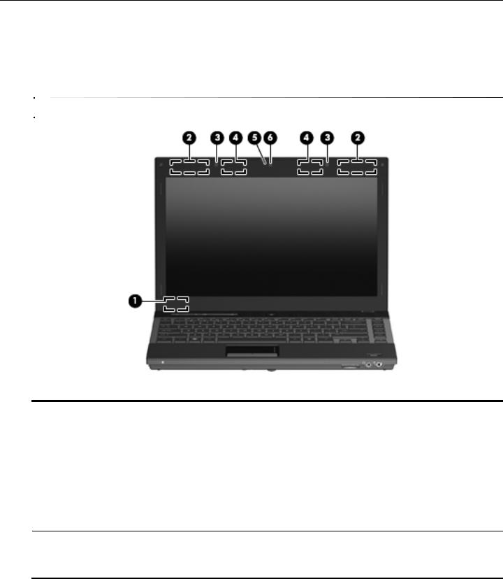
Your computer may look slightly different from the illustration in this section.
Item |
Component |
Description |
|
|
|
(1) |
Internal display switch |
Turns off the display if the display is closed while the power is on. |
|
|
|
(2) |
WWAN antennas (2)* |
Send and receive wireless signals to communicate with wireless wide-area |
|
|
networks (WWAN). |
|
|
|
(3) |
Internal microphones (2) |
Record sound. |
|
|
|
(4) |
WLAN antennas (2)* |
Send and receive wireless signals to communicate with wireless local area |
|
|
networks (WLAN). |
|
|
|
(5) |
Webcam light (select models only) |
On: The webcam is in use. |
|
|
|
(6) |
Webcam (select models only) |
Records audio and video and captures still photographs. |
*The antennas are not visible from the outside of the computer. For optimal transmission, keep the areas immediately around the antennas free from obstructions.
To see wireless regulation notices, refer to the section of the Regulatory, Safety and Environmental Notices that applies to your country or region. These notices are located in Help and Support.
Maintenance and Service Guide |
2–1 |
External component identification
Top components
Buttons and fingerprint reader
Item |
Component |
Description |
|
|
|
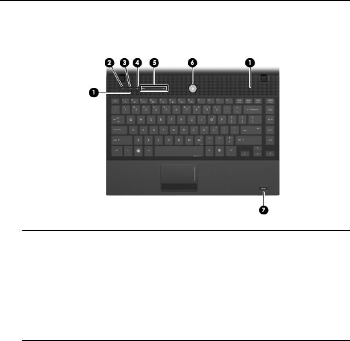
(1) |
Speakers (2) |
Produce sound. |
|
|
|
(2) |
Info Center/QuickLook button |
Launches Info Center or QuickLook. |
|
|
|
(3) |
Wireless button |
Turns the wireless feature on or off but does not establish a |
|
|
wireless connection. |
|
|
You must set up or access a wireless network to establish a |
|
|
wireless connection. |
|
|
|
(4) |
Volume mute button |
Mutes and restores speaker sound. |
|
|
|
(5) |
Volume scroll zone |
Adjusts speaker volume. Slide your finger to the left to decrease volume and |
|
|
to the right to increase volume. You can also press the left side of the volume |
slider to decrease volume, or press the right side of the volume slider to increase volume.
(Continued)
2–2 |
Maintenance and Service Guide |
|
|
|
External component identification |
|
|
|
|
|
|
|
|
|
Item |
Component |
Description |
|
|
|
|
(6) |
Power button |
■ When the computer is off, press the button to turn on the computer. |
|
|
|
|
■ When the computer is on, press the button to shut down the computer. |
|
|
|
■ When the computer is in the Sleep state (Standby in Windows XP), |
|
|
|
press the button briefly to exit Sleep (Standby). |
|
|
|
■ When the computer is in Hibernation, press the button briefly to |
|
|
|
exit Hibernation. |
|
|
|
If the computer has stopped responding and Windows shutdown procedures |
|
|
|
are ineffective, press and hold the power button for at least 5 seconds to turn |
|
|
|
off the computer. |
|
|
|
To learn more about your power settings: |
|
|
|
■ In Windows Vista: Select Start > Control Panel > System and |
|
|
|
Maintenance > Power Options. |
|
|
|
■ In Windows XP: Select Start > Control Panel > Performance and |
|
|
|
Maintenance > Power Options. |
|
|
|
|
(7) |
Fingerprint reader |
Allows a fingerprint logon to Windows instead of a password logon. |
|
|
|
(select models only) |
|
|
|
|
|
Maintenance and Service Guide |
2–3 |
External component identification
Keys
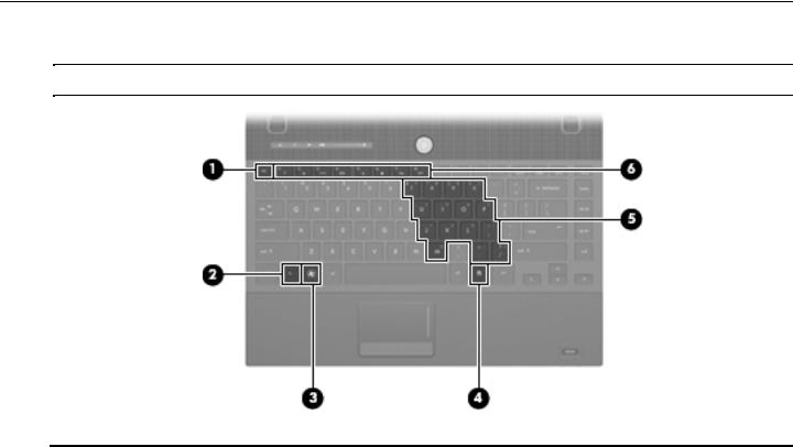
Your computer may look slightly different from the illustration in this section.
Item |
Component |
Description |
|
|
|
(1) |
esc key |
Displays system information when pressed in combination with the fn key. |
|
|
|
(2) |
fn key |
Executes frequently used system functions when pressed in combination with |
|
|
a function key or the esc key. |
|
|
|
(3) |
Windows logo key |
Displays the Windows Start menu. |
|
|
|
(4) |
Windows applications key |
Displays a shortcut menu for items beneath the pointer. |
|
|
|
(5) |
Embedded numeric keypad keys |
Can be used like the keys on an external numeric keypad. |
|
|
|
(6) |
Function keys |
Execute frequently used system functions when pressed in combination with |
|
|
the fn key. |
|
|
|
2–4 |
Maintenance and Service Guide |

External component identification
Lights
Your computer may look slightly different from the illustration in this section.
Item |
Component |
Description |
|
|
|
(1) |
Caps lock light |
On: Caps lock is on. |
|
|
|
(2) |
Info Center/QuickLook light |
■ On: The computer is on. |
|
|
■ Blinking (5 times): |
|
|
When the computer is on, press the button to launch Info Center. |
|
|
When the computer is off or in Hibernation, press the button to launch |
|
|
QuickLook. |
|
|
■ Off: The computer is off or in the Sleep (Standby in Windows XP) or |
|
|
Hibernation state. |
|
|
|
(3) |
Wireless light |
■ Blue: An integrated wireless device, such as a WLAN device and/or a |
|
|
Bluetooth device, is on. |
|
|
■ Amber: All wireless devices are off. |
|
|
|
(4) |
Volume mute light |
■ Turquoise: Computer sound is on. |
|
|
■ Amber: Computer sound is off. |
|
|
|
(5) |
Volume down light |
Blinking: The volume scroll zone is being used to decrease speaker volume. |
|
|
|
(6) |
Volume up light |
Blinking: The volume scroll zone is being used to increase speaker volume. |
|
|
|
(7) |
Power light |
■ On: The computer is on. |
|
|
■ Blinking: The computer is in the Sleep state (Standby in Windows XP). |
|
|
■ Off: The computer is off or in Hibernation. |
|
|
|
Maintenance and Service Guide |
2–5 |
External component identification
Pointing devices
Item |
Component |
Description |
|
|
|
(1) |
TouchPad* |
Moves the pointer and selects or activates items on the screen. |
|
|
|
(2) |
Left TouchPad button* |
Functions like the left button on an external mouse. |
|
|
|
(3) |
TouchPad scroll zone |
Scrolls up or down. |
|
|
|
(4) |
Right TouchPad button* |
Functions like the right button on an external mouse. |
*This table describes factory settings. To view or change pointing device preferences:
■For Windows Vista: Select Start > Control Panel > Hardware and Sound > Mouse.
■For Windows XP: Select Start > Control Panel > Printers and Other Hardware > Mouse.
2–6 |
Maintenance and Service Guide |

External component identification
Front components
Item |
Component |
Description |
|
|
|
(1) |
Drive light |
■ Blinking turquoise: The hard drive or optical drive is being accessed. |
|
|
■ Amber: HP 3D DriveGuard has temporarily parked the hard drive. |
|
|
|
(2) |
SD Card Reader |
Supports the following optional digital card formats: |
|
|
■ MultiMediaCard |
|
|
■ MultiMediaCard Plus |
|
|
■ Secure Digital Memory Card |
|
|
■ Secure Digital High Capacity Memory Card |
|
|
|
(3) |
Audio-out (headphone) jack |
Produces sound when connected to optional powered stereo speakers, |
|
|
headphones, ear buds, a headset, or television audio. |
|
|
When a device is connected to the headphone jack, the computer |
|
|
speakers are disabled. |
|
|
|
(4) |
Audio-in (microphone) jack |
Connects an optional computer headset microphone, stereo array |
|
|
microphone, or monaural microphone. |
|
|
|
Maintenance and Service Guide |
2–7 |

External component identification
Right-side components
Item |
Component |
Description |
|
|
|
(1) |
ExpressCard slot |
Supports optional ExpressCards. |
|
|
|
(2) |
USB port |
Connects an optional USB device. |
|
|
|
(3) |
HDMI port |
Connects an optional HDMI device. |
|
|
|
(4) |
External monitor port |
Connects an external VGA monitor or projector. |
|
|
|
(5) |
Vent |
Enables airflow to cool internal components. |
|
|
The computer fan starts up automatically to cool internal components |
|
|
and prevent overheating. It is normal for the internal fan to cycle on and |
|
|
off during routine operation. |
|
|
|
(6) |
RJ-45 (network) jack |
Connects a network cable. |
|
|
|
(7) |
Security cable slot |
Attaches an optional security cable to the computer. |
|
|
The security cable is designed to act as a deterrent, but it may not |
|
|
prevent the computer from being mishandled or stolen. |
|
|
|
2–8 |
Maintenance and Service Guide |

External component identification
Left-side components
Item |
Component |
Description |
|
|
|
(1) |
Battery light |
■ Amber: A battery is charging. |
|
|
■ Turquoise: A battery is close to full charge capacity. |
|
|
■ Blinking amber: A battery that is the only available power source has |
|
|
reached a low battery level. When the battery reaches a critical battery |
|
|
level, the battery light begins blinking rapidly. |
|
|
■ Off: If the computer is plugged into an external power source, the light turns |
|
|
off when all batteries in the computer are fully charged. If the computer is |
|
|
not plugged into an external power source, the light stays off until the |
|
|
battery reaches a low battery level. |
|
|
|
(2) |
Power connector |
Connects an AC adapter. |
|
|
|
(3) |
Optical drive (select models only) |
Reads optical discs and, on select models, also writes to optical discs. |
|
|
|
(4) |
RJ-11 (modem) jack |
Connects a modem cable. |
|
(select models only) |
|
|
|
|
(5) |
USB ports (2) |
Connect optional USB devices. |
|
|
|
Maintenance and Service Guide |
2–9 |
External component identification
Bottom components
Item |
Component |
Description |
|
|
|
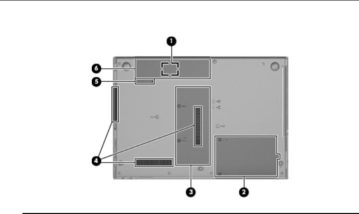
(1) |
SIM slot (select models only) |
Contains a wireless subscriber identity module (SIM). The SIM slot is located |
|
|
inside the battery bay. |
|
|
|
(2) |
Hard drive bay |
Holds the hard drive and a Bluetooth device. |
|
|
|
(3) |
Memory module compartment |
Contains the memory module slots and a wireless LAN module slot. |
|
|
Ä To prevent an unresponsive system and the display of a warning |
|
|
message, replace the WLAN module with only a module authorized for |
|
|
use in the computer by the governmental agency that regulates |
|
|
wireless devices in your country or region. If you replace the module |
|
|
and then receive a warning message, remove the module to restore |
|
|
computer functionality, and then contact technical support through Help |
|
|
and Support. |
|
|
|
(4) |
Vents (3) |
Enable airflow to cool internal components. |
|
|
The computer fan starts up automatically to cool internal components |
|
|
and prevent overheating. It is normal for the internal fan to cycle on and |
|
|
off during routine operation. |
|
|
|
(5) |
Battery release latch |
Releases the battery from the battery bay. |
|
|
|
(6) |
Battery bay |
Holds the battery. |
|
|
|
2–10 |
Maintenance and Service Guide |
3
Illustrated parts catalog
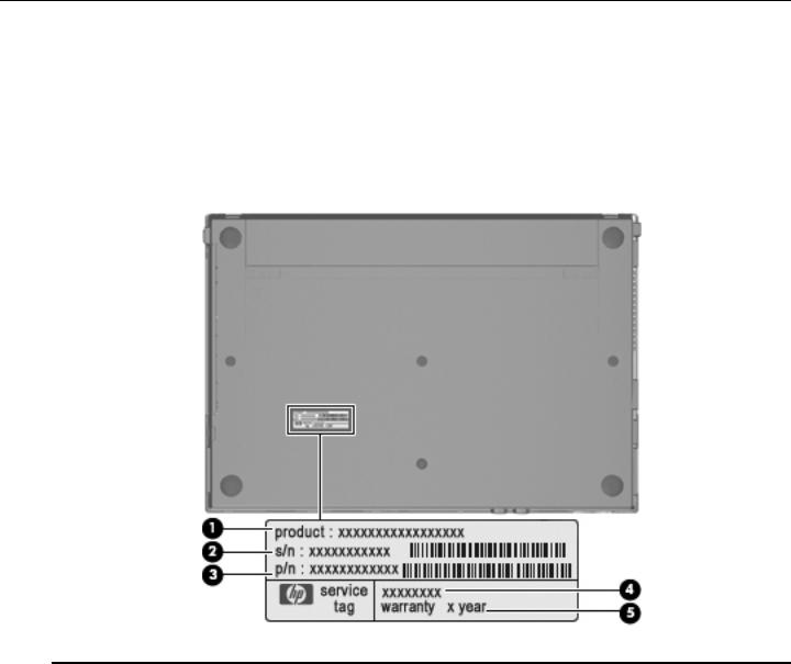
Service tag
When ordering parts or requesting information, provide the computer serial number and model number provided on the service tag.
Item |
Component |
Description |
|
|
|
(1) |
Product name |
This is the product name affixed to the front of the computer. |
|
|
|
(2) |
Serial number (s/n) |
This is an alphanumeric identifier that is unique to each product. |
|
|
|
(3) |
Part number/Product number (p/n) |
This number provides specific information about the product’s |
|
|
hardware components. The part number helps a service |
|
|
technician determine what components and parts are needed. |
|
|
|
(4) |
Model description |
This is the alphanumeric identifier used to locate documents, |
|
|
drivers, and support for the computer. |
|
|
|
(5) |
Warranty period |
This number describes the duration of the warranty period for |
|
|
the computer. |
|
|
|
Maintenance and Service Guide |
3–1 |

Illustrated parts catalog
Computer major components
3–2 |
Maintenance and Service Guide |

Illustrated parts catalog
Item Description |
Spare part number |
(1)13.3-in, LED, HD display assembly (includes 2 WLAN antenna transceivers and cables, nameplate, and logo):
■ AntiGlare display assembly with webcam and 2 WWAN antennas in black trim |
577173-001 |
■ AntiGlare display assembly with webcam and 2 WWAN antennas in red trim |
577182-001 |
■ AntiGlare display assembly with webcam in black trim |
577174-001 |
■ AntiGlare display assembly with webcam in red trim |
577183-001 |
■ AntiGlare display assembly without webcam in black trim |
577172-001 |
■ AntiGlare display assembly without webcam in red trim |
577181-001 |
|
|
■ 1366 × 768 BrightView display assembly with webcam and 2 WWAN antennas in |
577176-001 |
black trim |
|
■ 1366 × 768 BrightView display assembly with webcam and 2 WWAN antennas in red trim |
577185-001 |
■ 1366 × 768 BrightView display assembly with webcam in black trim |
577175-001 |
■ 1366 × 768 BrightView display assembly with webcam in red trim |
577184-001 |
■ 1366 × 768 BrightView display assembly without webcam in black trim |
577177-001 |
■ 1366 × 768 BrightView display assembly without webcam in red trim |
577186-001 |
|
|
■ 1280 × 720 BrightView display assembly with webcam and 2 WWAN antennas in |
583090-001 |
black trim |
|
■ 1280 × 720 BrightView display assembly with webcam and 2 WWAN antennas in red trim |
583091-001 |
■ 1280 × 720 BrightView display assembly with webcam in black trim |
577179-001 |
■ 1280 × 720 BrightView display assembly with webcam in red trim |
577188-001 |
■ 1280 × 720 BrightView display assembly without webcam in black trim |
577178-001 |
■ 1280 × 720 BrightView display assembly without webcam in red trim |
577187-001 |
See “Display assembly subcomponents” on page 3-10 for display assembly internal component spare part information.
(2)Switch cover (includes LED board and cable):
|
■ In black trim |
577207-001 |
|
■ In red trim |
577208-001 |
|
|
|
(3) |
Speakers (include cables) |
577215-001 |
(4)Keyboard (includes keyboard cable):
■ For use in Belgium |
577205-A41 |
■ For use in Brazil |
577205-201 |
■ For use in Bulgaria |
577205-261 |
■ For use in the Czech Republic |
577205-221 |
■ For use in Denmark |
577205-081 |
■ For use in France |
577205-051 |
■ For use in French Canada |
577205-121 |
■ For use in Germany |
577205-041 |
■ For use in Greece |
577205-DJ1 |
■ For use in Hungary |
577205-211 |
(Continued)
Maintenance and Service Guide |
3–3 |

Illustrated parts catalog
Item Description |
Spare part number |
(4)Keyboard (continued):
|
■ For use in Iceland |
577205-DD1 |
|
■ For use in Israel |
577205-BB1 |
|
■ For use in Italy |
577205-061 |
|
■ For use in Japan |
577205-291 |
|
■ For use in Latin America |
577205-161 |
|
■ For use in the Netherlands |
577205-B31 |
|
■ For use in Norway |
577205-091 |
|
■ For use in Portugal |
577205-131 |
|
■ For use in Russia |
577205-251 |
|
■ For use in Saudi Arabia |
577205-171 |
|
■ For use in Slovakia |
577205-231 |
|
■ For use in Slovenia |
577205-BA1 |
|
■ For use in South Korea |
577205-AD1 |
|
■ For use in Spain |
577205-071 |
|
■ For use in Sweden and Finland |
577205-B71 |
|
■ For use in Switzerland |
577205-BG1 |
|
■ For use in Taiwan |
577205-AB1 |
|
■ For use in Thailand |
577205-281 |
|
■ For use in Turkey |
577205-141 |
|
■ For use in the United Kingdom |
577205-031 |
|
■ For use in the United States |
577205-001 |
|
|
|
(5a) |
Palm rest (included with top cover spare part kit) |
|
(5b) |
Top cover (includes palm rest, TouchPad button board and cable, and TouchPad board and cable): |
|
|
■ For use only on computer models equipped with fingerprint reader in black trim (includes |
577216-001 |
|
fingerprint reader board and cable) |
|
|
■ For use only on computer models equipped with fingerprint reader in red trim (includes |
577218-001 |
|
fingerprint reader board and cable) |
|
|
■ For use only on computer models not equipped with fingerprint reader in black trim |
577217-001 |
|
■ For use only on computer models not equipped with fingerprint reader in red trim |
577219-001 |
|
|
|
(6) |
Bluetooth module |
537921-001 |
|
The Bluetooth module spare part kit does not include a Bluetooth module cable. The Bluetooth module cable is |
|
|
included in the Cable Kit, spare part number 577214-001. |
|
|
|
|
|
Plastics Kit, includes: |
577211-001 |
(7a) |
ExpressCard slot bezel |
|
(7b) |
SD Card Reader slot bezel |
|
(7c) |
Hard drive cover |
|
(7d) |
Memory/wireless module compartment cover |
|
|
See “Plastics Kit” on page 3-12 for more Plastics Kit spare part information. |
|
|
(Continued) |
|
|
3–4 |
Maintenance and Service Guide |

|
|
|
Illustrated parts catalog |
|
|
|
|
|
|
|
|
|
Item |
Description |
Spare part number |
|
|
|
|
|
|
Cable Kit, includes: |
577214-001 |
|
(8a) |
Modem module cable (includes RJ-11 connector) |
|
|
(8b) |
Bluetooth module cable |
|
|
(8c) |
Power connector cable |
|
|
(8d) |
Network cable (includes RJ-45 connector) |
|
|
|
See “Cable Kit” on page 3-9 for more Cable Kit spare part information. |
|
(9) |
USB board (includes cable) |
577659-001 |
|
(10)Modem module:
The modem module spare part kit does not include a modem module cable. The modem module cable is included in the Cable Kit, spare part number 577214-001.
■ |
For use in all countries and regions except Australia and New Zealand |
510100-001 |
■ |
For use only in Australia and New Zealand |
510100-011 |
(11)Power button board (includes two cables):
■ |
For use only on computer models equipped with WWAN capability (includes SIM slot) |
577662-001 |
■ |
For use only on computer models not equipped with WWAN capability |
577661-001 |
(12)System board (includes replacement thermal material):
PM45 system board for use only on computer models equipped with graphics subsystems with discrete memory:
|
■ For use only on computer models equipped with WWAN capability |
577223-001 |
|
■ For use only on computer models not equipped with WWAN capability |
577222-001 |
|
|
|
|
GM45 system board for use only on computer models equipped with graphics subsystems with UMA memory: |
|
|
■ For use only on computer models equipped with WWAN capability |
577225-001 |
|
■ For use only on computer models not equipped with WWAN capability |
577224-001 |
|
|
|
|
GL40 system board for use only on computer models equipped with graphics subsystems with UMA memory: |
|
|
■ For use only on computer models equipped with WWAN capability |
577221-001 |
|
■ For use only on computer models not equipped with WWAN capability |
577220-001 |
|
|
|
(13) |
RTC battery |
581926-001 |
(Continued)
Maintenance and Service Guide |
3–5 |
 Loading...