


 Loading...
HP MSM760 Controllers Installation Guide
Abstract
This document describes how to install and initially configure MSM760 Controllers. This information applies to the MSM760 Access Controller (J9421A) and the MSM760 Premium Mobility Controller (J9420A). These products are hereafter referred to as controller.
HP Part Number: 5998-6889
Published: November 2014
Edition: 1
© Copyright 2013, 2014 Hewlett-Packard Development Company, L.P.
The information contained herein is subject to change without notice. The only warranties for HP products and services are set forth in the express warranty statements accompanying such products and services. Nothing herein should be construed as constituting an additional warranty. HP shall not be liable for technical or editorial errors or omissions contained herein.
Acknowledgments
Microsoft® and Windows® are U.S. registered trademarks of Microsoft Corporation.
Warranty
WARRANTY STATEMENT: To obtain a copy of the warranty for this product, see the warranty information website:
http://www.hp.com/support/Networking-Warranties

Contents |
|
1 Preparing for installation............................................................................. |
4 |
Package contents...................................................................................................................... |
4 |
Identifying controller components................................................................................................ |
4 |
Installation precautions.............................................................................................................. |
7 |
2 Installing the controller................................................................................ |
8 |
Prepare the installation site ....................................................................................................... |
8 |
Installing the controller.............................................................................................................. |
8 |
3 Configuring the controller.......................................................................... |
11 |
Performing the initial configuration............................................................................................ |
11 |
Verifying guest access (optional)............................................................................................... |
12 |
Restarting the controller........................................................................................................... |
16 |
Resetting to factory defaults...................................................................................................... |
16 |
4 Working with controlled APs...................................................................... |
18 |
Verifying AP discovery............................................................................................................ |
18 |
Testing the wireless public access network.................................................................................. |
18 |
5 Support and other resources...................................................................... |
19 |
Online documentation............................................................................................................. |
19 |
Contacting HP........................................................................................................................ |
19 |
HP websites........................................................................................................................... |
19 |
Typographic conventions......................................................................................................... |
19 |
A Specifications.......................................................................................... |
20 |
Supported power cables.......................................................................................................... |
20 |
B Regulatory information.............................................................................. |
22 |
Contents 3
1 Preparing for installation
Package contents
The controllers are shipped with the following components:
•Console cable, DB-9 to RJ-45 (5188-6699)
•Accessory kit (5069-5705) which includes:
◦Two mounting brackets
◦Eight 8mm machine screws for attaching the mounting brackets to the controller
◦Four 5/8-inch number 12-24 screws for attaching the controller to a rack
◦Four rubber feet for horizontal mounting on a flat surface
•Documentation
•Power cable, see “Supported power cables” (page 20)
Identifying controller components
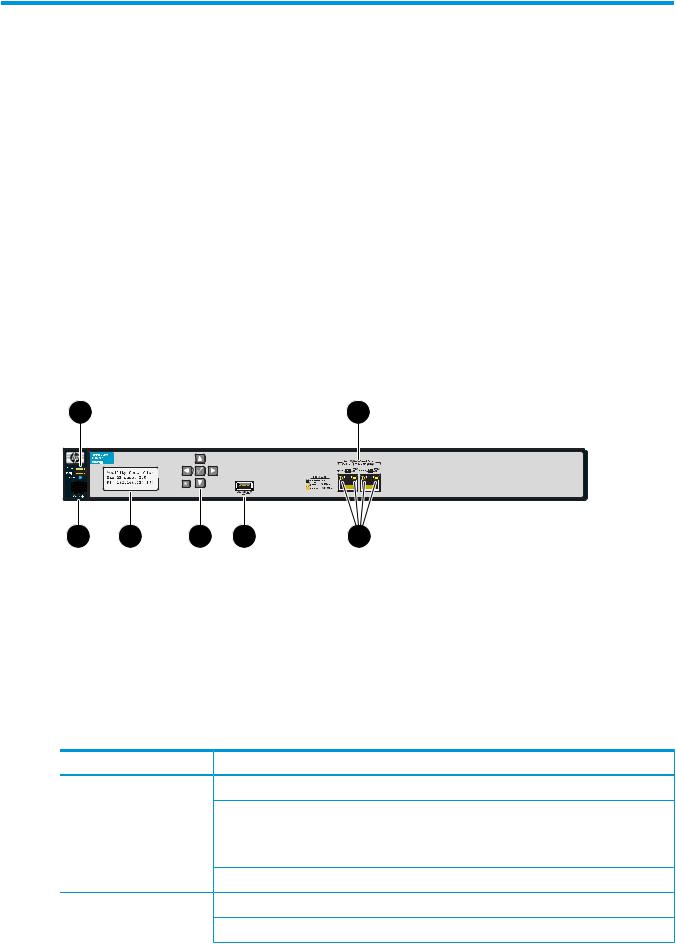
Figure 1 Front view of the controller
1 |
2 |
3 |
4 |
5 |
6 |
1.Power, Fault, and Locator LEDs
2.Ethernet Ports: 1=Internet, 2=LAN
3.Console port
4.LCD display
7 |
5.Keypad (not used)
6.USB port (not used)
7.Ethernet LEDs
LEDs
The following table indicates the function of the status LEDs. See Figure 1 (page 4) for the location of the status LEDs.
LED |
State |
Description |
Power (green) |
Off |
The controller has no power. |
|
Flashing |
The controller is starting up. A power LED that continues to flash |
|
|
after several minutes indicates that the firmware failed to load. |
|
|
Reset or power cycle the controller. If this condition persists, contact |
|
|
customer support. |
|
On |
The controller is fully operational. |
Fault (orange) |
Off |
There are no fault conditions on the controller. |
|
Flashing |
A fault has occurred on the controller. |
4Preparing for installation

LED |
State |
Description |
|
On |
On briefly at the beginning of the self-test after the controller is |
|
|
powered on or reset. If it remains on, the controller has encountered |
|
|
a fatal hardware failure, or has failed its self-test. For more |
|
|
information, see “Troubleshooting problems” (page 5). |
Locator (blue) |
On |
The Locator LED is used to locate a specific controller in a group |
|
|
of equipment, typically a rack. |
|
Off |
The standard state. |
Ethernet LEDs (right edge) |
Off |
No Ethernet link has been established. |
|
Flashing |
Transmit/receive activity is occurring. |
|
On |
An Ethernet link has been established, but there is no |
|
|
transmit/receive activity. |
Ethernet LEDs (left edge) |
Off |
Link speed 10 Mbps |
|
On (green) |
Link speed 100 Mbps |
|
On (orange) |
Link speed 1000 Mbps (gigabit) |
Troubleshooting problems
The following table shows LED patterns that indicate problem conditions.
LED indication |
Problem |
What to do |
The power LED is off, even though the power cable plugged in.
The controller is not plugged into an active AC power source.
1.Verify that the power cable is firmly attached to the controller and plugged into an active power source.
2.Power cycle the controller by unplugging and plugging the power cable back in.
3.If the power LED remains off, verify the AC power source by:
•Plugging another device into the outlet
•Plugging the controller power cable into a different outlet
•Using a different (approved) power cable
|
4. |
If the power source and power cable are good and this |
|
|
condition persists, the power supply might have failed. |
|
|
Call your HP authorized LAN dealer, or use the electronic |
|
|
support services from HP to get assistance. For more |
|
|
information, see the warranty information website: |
|
|
http://www.hp.com/support/Networking-Warranties |
The fault LED |
A hardware failure has occurred. 1. |
Power cycle the controller by unplugging and plugging |
remains on. |
|
the power cable back in. |
|
2. |
If this condition persists, the controller might have failed. |
|
|
Call your HP authorized LAN dealer, or HP customer |
|
|
support. For more information, see the warranty |
|
|
information website: |
http://www.hp.com/support/Networking-Warranties
Console port
The controller console port is a standard serial port with an RJ-45 connector. To connect to a computer, use the supplied DB-9 to RJ-45 console cable.
Identifying controller components |
5 |
LCD display
The LCD displays the following:
• The controller type, either Mobility Controller or Access Controller
•The maximum number of supported APs, according to the controller license
•The IP address of the Internet port.
During start up, the LCD displays a system booting message.
Until the controller receives its IP address from a DHCP server, the address displays as: 0.0.0.0
Keypad
The keypad is not used in this release.
USB port
The USB port is not used in this release.
MAC address
The Internet port MAC address is printed on the front of the controller. The LAN port MAC address is the Internet port MAC address plus 1.
Ethernet ports
The controller has two auto-sensing 10/100/1000 Ethernet ports with RJ-45 connectors. Connector 1 (on the left) is used for the Internet port and connector 2 (on the right) is used for the LAN port. Ethernet status LEDs on the left and right edges of the RJ-45 connectors indicate speed and activity.
6Preparing for installation

Installation precautions
Observe the following precautions when installing the controller.
WARNING!
•The rack or cabinet must be adequately secured to prevent it from becoming unstable and falling over.
Install products as low as possible in a rack or cabinet, with the heaviest devices at the bottom and progressively lighter devices installed above.
•For safe operation, only install the controller horizontally, with the bottom side down.
CAUTION:
•Ensure that the power source circuits are properly grounded, and use the power cable supplied with the controller to connect it to the power source.
•If your installation requires a different power cable than the one supplied with the controller, be sure to use a power cable displaying the mark of the safety agency that defines the regulations for power cables in your country. The mark is your assurance that the power cable can be used safely with the controller.
•Connect the controller to an AC outlet that is easily accessible in case the controller must be powered off.
•Ensure the controller does not overload the power circuits, wiring, and over-current protection. To determine the possibility of overloading the supply circuits, add together the ampere ratings of all devices installed on the same circuit as the controller and compare the total with the rating limit for the circuit. The maximum ampere ratings are typically printed on the devices near the AC power connectors.
•Do not install the controller in an environment where the operating ambient temperature might exceed 40°C (104°F).
•Ensure the air flow around the sides and back of the controller is not restricted.
Installation precautions |
7 |
Loading...