


 Loading...
HP MSR 93X Routers
Installation Guide
Part number: 5998-6569
Document version: 6W103-20140813
Legal and notice information
© Copyright 2014 Hewlett-Packard Development Company, L.P.
No part of this documentation may be reproduced or transmitted in any form or by any means without prior written consent of Hewlett-Packard Development Company, L.P.
The information contained herein is subject to change without notice.
HEWLETT-PACKARD COMPANY MAKES NO WARRANTY OF ANY KIND WITH REGARD TO THIS MATERIAL, INCLUDING, BUT NOT LIMITED TO, THE IMPLIED WARRANTIES OF MERCHANTABILITY AND FITNESS FOR A PARTICULAR PURPOSE. Hewlett-Packard shall not be liable for errors contained herein or for incidental or consequential damages in connection with the furnishing, performance, or use of this material.
The only warranties for HP products and services are set forth in the express warranty statements accompanying such products and services. Nothing herein should be construed as constituting an additional warranty. HP shall not be liable for technical or editorial errors or omissions contained herein.

Contents
Preparing for installation ············································································································································· 1
Safety recommendations ··················································································································································1 Site requirements·······························································································································································2 ESD prevention ·························································································································································2 EMI·············································································································································································3 Lightning protection··················································································································································3 Installation accessories ·····················································································································································3 Pre-installation checklist ····················································································································································4
Installing the router······················································································································································· 5
Installation prerequisites ···················································································································································5 Installation flowchart·························································································································································5 Installing the router····························································································································································6 Mounting the router on a workbench·····················································································································6 Installing the router on a wall··································································································································7 Grounding the router ···············································································································································8 Installing a standard 3G SIM card·························································································································9 Installing a 3G antenna········································································································································ 11 Installing WLAN antennas···································································································································· 13 Installing a standard 4G SIM card······················································································································ 13 Installing a 4G antenna········································································································································ 16 Installing a 3G/4G antenna extender cable to a 4G device ·········································································· 16 Installing a GPS antenna ······································································································································ 17 JG704A router antenna installation instructions ································································································ 17 Connecting interface cables································································································································· 18 Connecting the console cable and setting terminal parameters ······································································ 19 Setting console terminal parameters ··················································································································· 19 Connecting the power adapter···························································································································· 22 Verifying the installation ······································································································································· 23 Powering on the router ·················································································································································· 23 Startup process ······················································································································································ 23 Power-on check······················································································································································ 24 Configuring basic settings for the router············································································································· 25
Troubleshooting··························································································································································26
Power supply failure ······················································································································································ 26 System configuration problems····································································································································· 26 No terminal display ·············································································································································· 26 Garbled terminal display······································································································································ 26 No response from the serial port························································································································· 27
Password loss ································································································································································· 27 User password loss ··············································································································································· 27 Super password loss ············································································································································· 27 3G/4G SIM card and 3G/4G antenna failures ······································································································· 28 Restoring the factory settings ········································································································································ 28 Scenario 1······························································································································································ 28 Scenario 2······························································································································································ 29 Scenario 3······························································································································································ 29 Reset button usage guidelines······························································································································ 29
i
Appendix A Chassis views and technical specifications ························································································30
Chassis views ································································································································································· 30 JG511A·································································································································································· 30 JG512A·································································································································································· 31 JH012A ·································································································································································· 31 JG513A·································································································································································· 32 JG514A·································································································································································· 33 JG515A·································································································································································· 33 JG531A·································································································································································· 34 JG516A·································································································································································· 35 JG517A·································································································································································· 35 JG518A·································································································································································· 36 JG519A·································································································································································· 37 JH013A ·································································································································································· 37 JG520A·································································································································································· 38 JG596A·································································································································································· 39 JG665A·································································································································································· 39 JG704A·································································································································································· 40 JG597A·································································································································································· 41
Technical specifications················································································································································· 41 Antenna specifications··················································································································································· 43
Appendix B LEDs························································································································································45
LEDs ················································································································································································· 45 JG511A·································································································································································· 45 JG512A·································································································································································· 45 JH012A ·································································································································································· 46 JG513A·································································································································································· 47 JG514A·································································································································································· 47 JG515A·································································································································································· 48 JG531A·································································································································································· 49 JG516A·································································································································································· 49 JG517A·································································································································································· 50 JG518A·································································································································································· 51 JG519A·································································································································································· 51 JH013A ·································································································································································· 52 JG520A·································································································································································· 53 JG596A·································································································································································· 53 JG665A·································································································································································· 54 JG704A·································································································································································· 55 JG597A·································································································································································· 55
LED description······························································································································································· 56
Support and other resources ·····································································································································59
Contacting HP ································································································································································ 59 Subscription service ·············································································································································· 59 Related information························································································································································ 59 Documents······························································································································································ 59 Websites································································································································································· 59 Conventions ···································································································································································· 60
Index ···········································································································································································62
ii

Preparing for installation
Table 1 HP MSR93X router models
Product code |
HP description |
RMN |
JG511A |
HP MSR930 Router |
BJNGA-BB0015 |
|
|
|
JG513A |
HP MSR930 3G Router |
BJNGA-BB0016 |
|
|
|
JG514A |
HP MSR931 Router |
BJNGA-BB0017 |
|
|
|
JG515A |
HP MSR931 3G Router |
BJNGA-BB0018 |
|
|
|
JG531A |
HP MSR931 Dual 3G Router |
BJNGA-BB0019 |
|
|
|
JG512A |
HP MSR930 Wireless Router |
BJNGA-BB0020 |
|
|
|
JH012A |
HP MSR930 Wireless Router NA |
BJNGA-BB0020 |
|
|
|
JG516A |
HP MSR933 Router |
BJNGA-BB0021 |
|
|
|
JG517A |
HP MSR933 3G Router |
BJNGA-BB0022 |
|
|
|
JG518A |
HP MSR935 Router |
BJNGA-BB0023 |
|
|
|
JG519A |
HP MSR935 Wireless Router |
BJNGA-BB0024 |
|
|
|
JH013A |
HP MSR935 Wireless Router NA |
BJNGA-BB0024 |
|
|
|
JG520A |
HP MSR935 3G Router |
BJNGA-BB0025 |
|
|
|
JG596A |
HP MSR930 4G LTE/3G CDMA Router |
BJNGA-BB0026 |
|
|
|
JG665A |
HP MSR930 4G LTE/3G WCDMA Router |
BJNGA-BB0027 |
|
|
|
JG704A |
HP MSR930 4G LTE/3G WCDMA ATT Router |
BJNGA-BB0033 |
|
|
|
JG597A |
HP MSR936 Wireless Router |
BJNGA-BB0028 |
|
|
|
Safety recommendations
WARNING!
Before installation and operation, read all the safety instructions in the compliance and safety guide for your router.
Follow these general safety recommendations:
•Turn off all power and remove all power cables before opening the chassis.
•Unplug all power and external cables before moving the chassis.
•Before installation, locate the emergency power switch so that you can shut off power immediately if necessary.
•Always wear an ESD wrist strap when installing the router.
•Do not stare into an open optical interface. The light can cause permanent eye damage.
•Use a good grounding system. This is essential for reliable operation.
1

•Confirm that the resistance between the chassis and the ground is less than 1 ohm.
Site requirements
The router can only be used indoors.
This section provides information about temperature, humidity, cleanness, and air quality requirements, as well as rack-mounting requirements and protection against damage from lightning and EMI.
Table 2 Temperature and humidity requirements
Temperature |
Relative humidity |
0°C to 40°C (32°F to 104°F) |
5% to 90% |
|
|
Table 3 Dust concentration limit in the equipment room |
|
|
|
Substance |
Concentration limit (particles/m3) |
Dust particles |
≤ 3 x 10⁴ (No visible dust on desk in three days) |
NOTE: |
|
Dust particle diameter ≥ 5 μm |
|
|
|
Table 4 Harmful gas concentration limits |
|
|
|
Gas |
Max. (mg/m3) |
SO2 |
0.2 |
H2S |
0.006 |
|
|
NH3 |
0.05 |
Cl2 |
0.01 |
|
|
To prevent overheating:
•Provide adequate clearance for air flow, including at least 10 cm (3.94 in) ventilation space around the router's air intake and outlet vents.
•Make sure the site has an adequate cooling system.
ESD prevention
To prevent the electronic components from being damaged by ESD, follow these guidelines:
•The equipment and floor are correctly grounded.
•The equipment room is dust-controlled.
•Wear an ESD wrist strap when inspecting or handling a circuit board.
To attach an ESD wrist strap:
1.Wear the wrist strap on your wrist.
No wrist strap is supplied with the router. Prepare it yourself.
2.Lock the wrist strap tight around your wrist to keep good contact with the skin.
3.Insert the ESD plug into the ESD socket in the chassis.
2
4.Attach the alligator to the chassis.
IMPORTANT:
Check the resistance of the ESD wrist strap for safety. The resistance reading should be in the range of 1 to 10 megohm (Mohm) between human body and the ground.
EMI
EMI from any source adversely affects the router.
To prevent EMI:
•Use electromagnetic shielding when necessary.
•Take measures against interference from the power grid.
•Position the router as far as possible from any power source's grounding equipment or light-prevention equipment.
•Position the router as far as possible from radio transmitters, radar, and all high-voltage or high-frequency equipment.
Lightning protection
To protect the router from lightning:
•Make sure the grounding cable of the chassis is grounded correctly.
•Make sure the grounding terminal of the AC power receptacle is grounded correctly.
•Install a lightning arrester at the input end of the power supply.
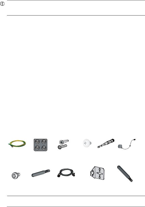
Installation accessories
Figure 1 lists the installation accessories for the router.
Figure 1 Installation accessories
NOTE:
The type of the antenna that comes with the router depends on the router model.
3

Pre-installation checklist
Item |
|
Requirements |
Yes No |
|
|
• There is a minimum clearance of 10 cm (3.9 in) around |
|
|
Ventilation |
the router chassis intake and exhaust vents for heat |
|
|
dissipation. |
|
|
|
|
|
|
|
|
• The installation site ventilation system is adequate. |
|
|
|
|
|
|
Temperature |
0°C to 40°C (32°F to 104°F) |
|
|
|
|
|
|
Relative humidity |
5% to 90% (noncondensing) |
|
|
|
|
|
|
Cleanness |
Dust concentration ≤ 3 × 10⁴ particles/m3 |
|
|
|
• The equipment and floor are correctly grounded. |
|
|
|
• The equipment room is dust-controlled. |
|
|
ESD prevention |
• Humidity and temperature are maintained at acceptable |
|
|
levels. |
|
|
|
|
|
|
|
|
• Wear an ESD wrist strap when inspecting or handling a |
|
|
|
circuit board. |
|
|
|
|
|
|
|
• Take measures to protect the power system from the |
|
|
|
power grid system. |
|
Installation |
|
• Keep the protection ground of the router as far away from |
|
|
the grounding device or lightning protection grounding |
|
|
site |
EMI prevention |
|
|
device as possible. |
|
||
|
|
||
|
|
|
|
|
|
• Keep the router far away from radio transmitters, radar, |
|
|
|
and high-frequency or high-voltage devices. |
|
|
|
• Use electromagnetic shielding when necessary. |
|
|
|
|
|
|
|
• The grounding cable of the chassis is grounded correctly. |
|
|
|
• The grounding terminal of the AC power receptacle is |
|
|
|
grounded correctly. |
|
|
Lightning protection |
• A port lightning arrester is installed. (Optional.) |
|
|
|
• A power lightning arrester is installed. (Optional.) |
|
|
|
• A signal lightning arrester is installed at the input end of |
|
|
|
an external signal cable. (Optional.) |
|
|
|
|
|
|
|
• Install a UPS. |
|
|
Electricity safety |
• In case of emergency during operation, switch off the |
|
|
|
external power switch. |
|
|
|
|
|
|
Workbench |
• The workbench is stable. |
|
|
• The workbench is grounded correctly. |
|
|
|
|
|
|
|
|
|
|
Safety |
• The router is far away from any sources of heat or moisture. |
|
|
precautions |
• The emergency power switch in the equipment room is identified and accessible. |
|
|
|
|
|
|
Installation |
• Installation accessories supplied with the router are ready. |
|
|
accessories |
• User-supplied accessories and tools are ready. |
|
|
and tools |
|
|
|
Reference |
• Documents shipped with the router are available. |
|
|
• Online documents are available. |
|
||
|
|
|
|
4
Installing the router
WARNING!
To avoid injury, do not touch bare wires, terminals, or parts with high-voltage hazard signs.
IMPORTANT:
•The barcode on the router chassis contains product information that must be provided to HP Support before you return a faulty router for service.
•Keep the tamper-proof seal on a mounting screw on the chassis cover intact, and if you want to open the chassis, contact HP for permission. Otherwise, HP shall not be liable for any consequence.
Installation prerequisites
•You have read "Preparing for installation" carefully.
•All requirements in "Preparing for installation" are met.
Installation flowchart
You can install the router on a workbench or on a wall. Select an installation method according to the installation environment, and follow the installation flowchart shown in Figure 2.
5
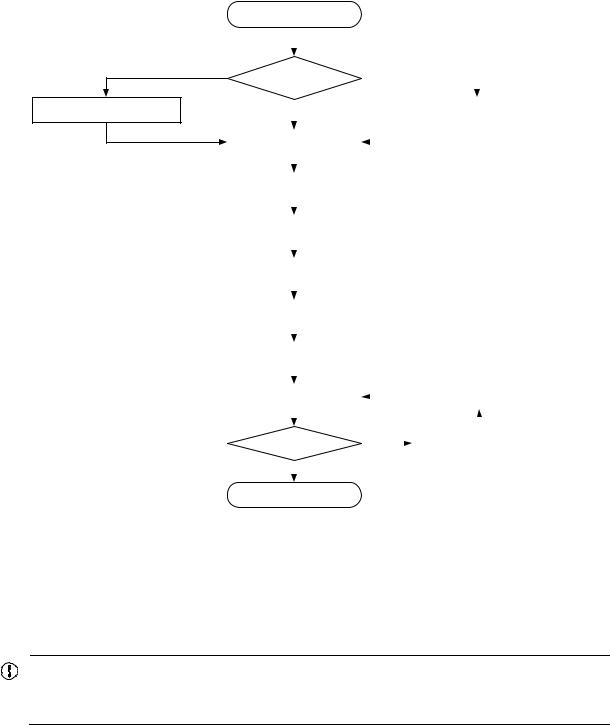
Figure 2 Installation flowchart
Mount the router on a workbench
Check the workbench
Start |
|
|
|
|
|
|
|
|
|
Install the router on a wall |
|||||
|
|
||||||
|
|
||||||
Install the router |
|
|
|
|
|
|
|
|
|
|
|
|
|
||
|
|
|
|
|
|
|
|
|
|
|
|
|
|
|
|
|
|
|
|
|
Install wall-mounting screws |
||
|
|
|
|
|
|
|
|
|
|
|
|
|
|
|
|
Ground the router |
|
|
|
|
|
|
|
|
|
|
|
|
|
||
|
|
|
|
|
|
|
|
|
|
|
|
|
|
|
|
|
|
|
|
|
|
|
|
Install antennas |
|
|
|
|
|
|
|
|
|
|
|
|
|
|
|
|
|
|
|
|
|
|
|
|
|
|
|
|
|
|
|
Connect interface cables |
|
|
|
|
|
|
|
|
|
|
|
|
|
|
|
|
|
|
|
|
|
|
|
|
|
|
|
|
|
|
|
Connect the router to a console |
|
|
|
|
|
|
|
terminal |
|
|
|
|
|
|
|
|
|
|
|
|
|
|
|
|
|
|
|
|
|
|
|
Connect the power adapter |
|
|
|
|
|
|
|
|
|
|
|
|
|
|
|
|
|
|
|
|
|
|
|
|
|
|
|
|
|
|
|
Verify the installation |
|
|
|
|
|
|
|
|
|
|
|
|
|
|
|
|
|
|
|
|
|
|
|
|
|
|
|
|
|
||
Power on the router |
|
|
|
Troubleshoot the router |
|
||
|
|
|
|||||
|
|
|
|
|
|
|
|
|
|
|
|
|
|
|
|
|
|
|
|
|
|
|
|
Operate correctly ? |
|
|
|
Power off the router |
|
||
|
No |
||||||
|
Yes |
|
|
|
|||
|
|
|
|
||||
|
|||||||
|
|
|
|
|
|
|
|
|
|
|
|
|
|
|
|
End |
|
|
|
|
|
|
|
Installing the router
Mounting the router on a workbench
IMPORTANT:
•Ensure good ventilation and 10 cm (3.9 in) of clearance around the chassis for heat dissipation.
•Avoid placing heavy objects on the router.
To mount the router on a workbench:
1.Make sure the workbench is clean, stable, and correctly grounded.
2.Place the router upside down on the workbench and attach the rubber feet to the four round holes in the chassis bottom.
6
Figure 3 Mounting the router on a workbench
Installing the router on a wall
CAUTION:
When mounting the router on a wall, position the router so the network interfaces face downwards, and the sides with ventilation openings are perpendicular to the ground, as shown in Figure 4.
To mount the router on a wall:
1.Mark the locations of the two mounting holes on the wall with the separations listed as follows:
Router model |
Separation |
|
JG511A, JG512A, JH012A, JG513A, JG596A, JG665A, and |
180 mm (7.09 in) |
|
JG704A |
||
|
||
|
|
|
JG514A, JG515A, JG531A, JG516A, JG517A, JG518A, JG519A, |
240 mm (9.45 in) |
|
JH013A, JG520A, and JG597A |
||
|
||
|
|
The holes must be level (on the same horizontal line).
2.Drill two holes in the wall.
3.Following the marks, drill the two holes at least 22 mm (0.87 in) deep. Verify that the holes are level.
4.Insert an anchor into each hole so it is flush with the wall surface.
5.Drive a screw into each anchor, keeping the screw heads protruding at least 1.5 mm (0.06 in) from the wall.
6.Hang the router on the screws.
7
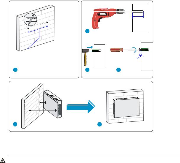
Figure 4 Wall-mounting the router
Grounding the router
WARNING!
Connecting the router grounding cable correctly is crucial for protecting the router from lightning and EMI.
Make sure the grounding resistance is less than 5 ohms.
You can ground the router with a grounding strip or to a buried grounding conductor.
Grounding the router with a grounding strip
1.Remove the grounding screw from the router chassis.
2.Put the ring terminal of the grounding cable on the grounding screw.
3.Use a screwdriver to fasten the grounding screw.
4.Attach the other end of the grounding cable to the grounding strip.
8
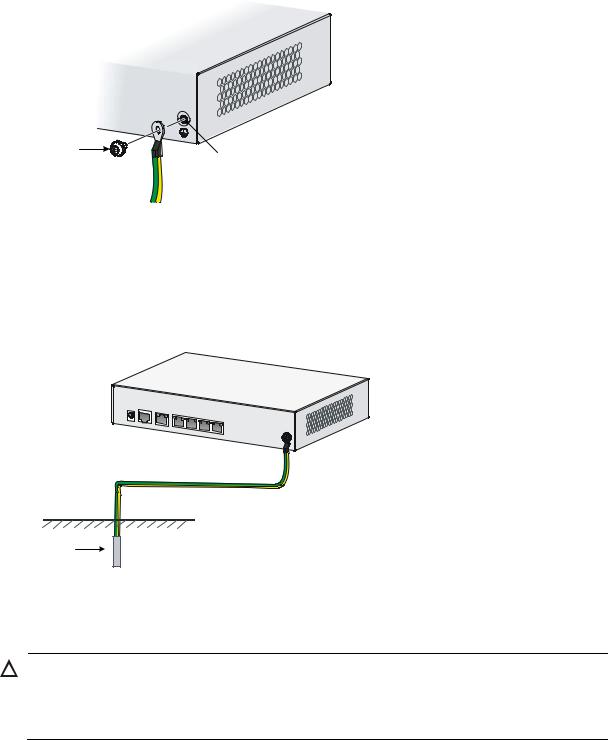
Figure 5 Connecting the grounding cable to the router
Grounding the router to a buried grounding conductor
If the installation site has no grounding strips but offers the option of grounding to earth, hammer a 0.5 m (1.64 ft) or longer angle iron or steel tube into the earth to serve as a grounding conductor, as shown in Figure 6.
Figure 6 Grounding to a conductor buried in the earth
Installing a standard 3G SIM card
CAUTION:
•Do not install or remove a standard 3G SIM card when the router is powered on.
•To avoid damage to the holder, do not use excessive strength when you install the standard 3G SIM card.
The HP MSR93X routers support the following frequency ranges:
•3G—800/850/900/1900/2100 MHz WCDMA/HSDPA/HSUPA/HSPA+
•2G—850/900/1800/1900 MHz GSM/GPRS/EGPRS
To install a standard 3G SIM card:
9
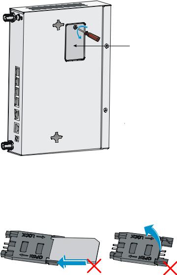
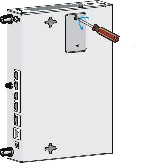
1.Use a screwdriver to loosen the screws on the 3G SIM card socket cover on the bottom of the chassis, and remove the cover.
Figure 7 Removing the 3G SIM card socket cover
2.Push the 3G SIM card holder in the direction marked "OPEN" so the holder projects upwards. Do not directly insert the standard 3G SIM card into the holder, or lift the holder.
Figure 8 illustrates the wrong installation methods.
Figure 8 Wrong installation methods
3.Insert the standard 3G SIM card along the slide rails to the holder.
4.Put down the holder and push the holder in the direction marked "LOCK" to lock the card in position.
10
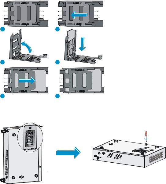
Figure 9 Installing the standard 3G SIM card
5.Position the socket cover and use a screwdriver to fasten the screws on the cover.
Figure 10 Installing the cover
Installing a 3G antenna
To install a 3G antenna:
1.Thread the male connector of the 3G cable through the hole on the bracket, and use screws (from behind the bracket) to secure the male connector to the bracket.
2.Change the angle of the antenna orientation from vertical to horizontal.
3.Attach the antenna to the male connector of the cable.
4.Attach the female connector of the cable to the router.
11
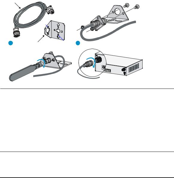
Figure 11 Installing a 3G antenna
3G/4G antenna extension cable
M6
M3

1 |
Antenna extension |
M2.9 |
2 |
|
cable bracket
NOTE:
•A 3G module is provided with a 3G antenna and a 3G extender cable. Connect the 3G antenna to the port marked "MAIN" by using the 3G extender cable. Ensure a minimum of 25 cm (9.84 in) distance between the 3G antenna and the chassis and between the 3G antenna and any other antenna installed on or connected to the router.
•When a second 3G antenna is required, purchase the other 3G antenna and 3G extender cable yourself. Attach the second 3G antenna to the port marked "DIV" if no antennas are installed on the router or connect the second 3G antenna to the port marked "DIV" by using the 3G extender cable if the router has antennas installed. Ensure a minimum of 25 cm (9.84 in) distance between the 3G antenna (when the extender cable is used) and the chassis and between the 3G antenna and any other antenna installed on or connected to the router.
Table 5 lists HP extender cables. You can use HP extender cables, but HP is not liable for any consequences caused thereby.
Table 5 3G extender cables
J Number |
Extender Cable |
JG522A |
HP MSR 2.8m Extender Cable |
|
|
JG666A |
HP MSR 6m Extender Cable |
|
|
JG667A |
HP MSR 15m Extender Cable |
|
|
On a dual-3G JG531A router, the 3G SIM1 and 3G SIM2 cards are associated with the two antenna connectors on the front and rear panels, respectively. Make sure you install the antennas at the correct positions.
12
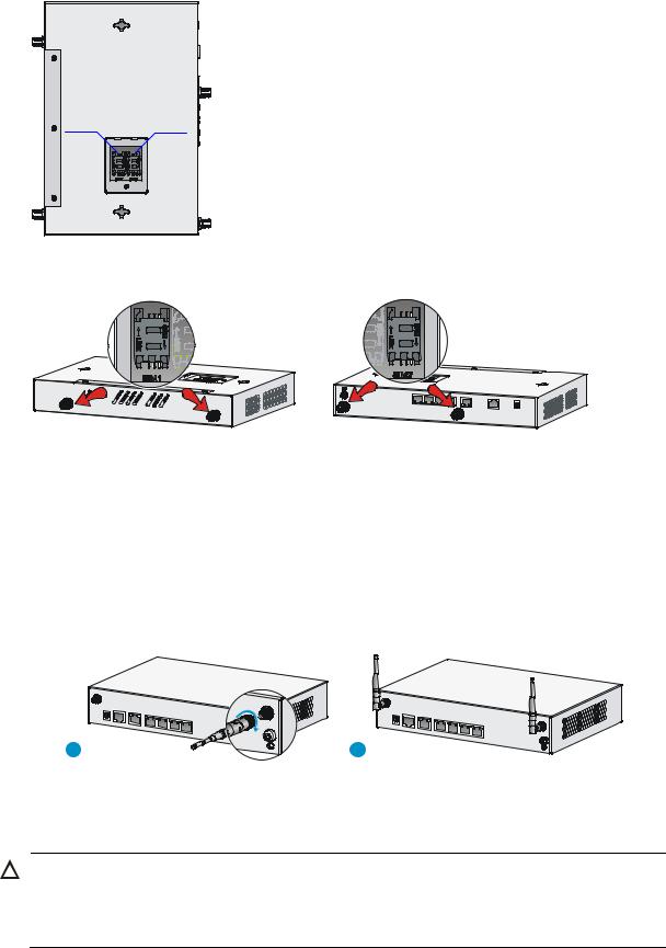
Figure 12 SIM card locations on a dual-3G JG531A router
Figure 13 SIM cards and antenna connectors
Installing WLAN antennas
1.Change the angle of the antenna orientation from vertical to horizontal.
2.Attach the antenna to the router, as shown in Figure 14. Avoid over-tightening.
3.Install the other antenna in the same way.
Change the antenna orientation to vertical to achieve better signal coverage.
Figure 14 Installing WLAN antennas
Installing a standard 4G SIM card
CAUTION:
•Do not install or remove a standard 4G SIM card when the router is powered on.
•To avoid damage to the holder, do not use excessive strength when you install the standard 4G SIM card.
13
The JG596A router supports the following frequency ranges:
•4G—700 MHz LTE
•3G—800/1900 MHz CDMA
The JG704A router supports the following frequency ranges:
•4G—700/1700/2100 MHz LTE
•3G—800/850/1900/2100 MHz WCDMA/HSDPA/HSUPA/HSPA+/DC-HSPA+
•2G—850/900/1800/1900 MHz GSM/GPRS/EDGE
The JG665A router supports the following frequency ranges:
•4G—DD800/900/1800/2100/2600 MHz LTE
•3G—900/2100 MHz WCDMA/HSDPA/HSUPA/HSPA+
•2G—900/1800/1900 MHz GSM/GPRS/EDGE
To install a standard 4G SIM card:
1.Use a screwdriver to loosen the screws on the standard 4G SIM card socket cover on the bottom of the chassis, and remove the cover.
Figure 15 Removing the 4G SIM card socket cover
2.Push the 4G SIM card holder in the direction marked "OPEN" so the holder projects upwards. Do not directly insert the standard 4G SIM card into the holder, or lift the holder.
Figure 16 illustrates the wrong installation methods.
14

Figure 16 Incorrect installation methods
3.Insert the standard 4G SIM card along the slide rails to the holder.
4.Put down the holder and push the holder in the direction marked "LOCK" to lock the standard 4G SIM card in position.
Figure 17 Installing the standard 4G SIM card
5.Position the socket cover and use a screwdriver to fasten the screws on the cover.
Figure 18 Installing the cover
15
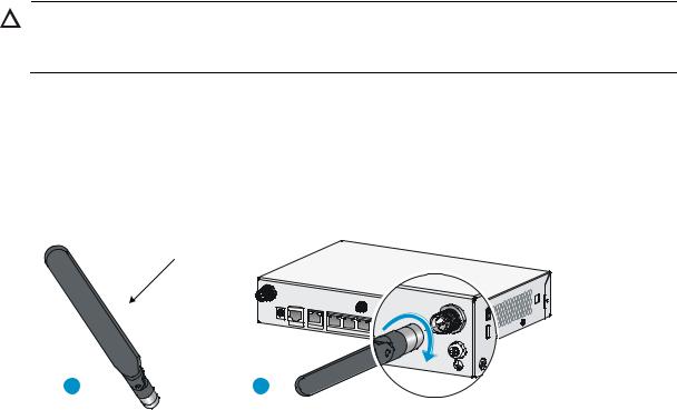
Installing a 4G antenna
CAUTION:
When you install two 4G antennas on a JG704A router, connect one or both of the antennas to the router by using antenna extender cables.
To install a 4G antenna:
1.Change the angle of the antenna orientation from vertical to horizontal.
2.Attach the antenna to the router, as shown in Figure 19. Avoid over-tightening. Change the antenna orientation to vertical to achieve better signal coverage.
Figure 19 Installing a 4G antenna
4G antenna
1 |
2 |
Installing a 3G/4G antenna extender cable to a 4G device
One 3G/4G antenna extender cable is provided with the JG704A router. No 3G/4G antenna extender cable is provided with other router models. Purchase 3G/4G antenna extender cables as required.
To install a 3G/4G antenna extender cable to a 4G device:
1.Thread the male connector of the cable through the hole on the bracket, and use screws (from behind the bracket) to secure the male connector to the bracket.
2.Change the angle of the antenna orientation from vertical to horizontal.
3.Attach the antenna to the male connector of the cable.
4.Attach the female connector of the cable to the router.
16
Figure 20 Installing the 3G/4G antenna extender cable to a 4G device
Installing a GPS antenna
1.Attach one end of the antenna to the GPS antenna connector on the router, as shown in Figure 21. Avoid over-tightening.
2.Attach the magnetic end of the antenna to a metal media near the router.
Figure 21 Installing a GPS antenna
JG704A router antenna installation instructions
When you install a 4G or GPS antenna to a JG704A router, follow these guidelines:
•Ensure a minimum distance of 25 cm (9.84 in) between the antenna and any other antenna on the router.
•Ensure a minimum distance of 25 cm (9.84 in) between the GPS antenna or the 4G antenna (when an extender cable is used) and the router.
17
Loading...