


MSA 1040
Table of contents
 Loading...
HP MSA 1040
User Guide
Abstract
This document describes initial hardware setup for HP MSA 1040 controller enclosures, and is intended for use by storage system
administrators familiar with servers and computer networks, network administration, storage system installation and configuration,
storage area network management, and relevant protocols.
HP Part Number: 762783-001
Published: March 2014
Edition: 1

© Copyright 2014 Hewlett-Packard Development Company, L.P.
Confidential computer software. Valid license from HP required for possession, use or copying. Consistent with FAR 12.211 and 12.212, Commercial
Computer Software, Computer Software Documentation, and Technical Data for Commercial Items are licensed to the U.S. Government under
vendor's standard commercial license.
The information contained herein is subject to change without notice. The only warranties for HP products and services are set forth in the express
warranty statements accompanying such products and services. Nothing herein should be construed as constituting an additional warranty. HP shall
not be liable for technical or editorial errors or omissions contained herein.
Acknowledgments
Microsoft® and Windows® are U.S. registered trademarks of Microsoft Corporation.
UNIX® is a registered trademark of The Open Group.
Warranty
WARRANTY STATEMENT: To obtain a copy of the warranty for this product, see the warranty information website:
http://www.hp.com/go/storagewarranty

Contents
1 Overview . . . . . . . . . . . . . . . . . . . . . . . . . . . . . . . . . . . . . . . . . . . . . . . . . . . . . . . . 11
MSA 1040 Storage models . . . . . . . . . . . . . . . . . . . . . . . . . . . . . . . . . . . . . . . . . . . . . . . . . . . . . . . . 11
Features and benefits . . . . . . . . . . . . . . . . . . . . . . . . . . . . . . . . . . . . . . . . . . . . . . . . . . . . . . . . . . . . 11
2 Components . . . . . . . . . . . . . . . . . . . . . . . . . . . . . . . . . . . . . . . . . . . . . . . . . . . . . . 13
Front panel components . . . . . . . . . . . . . . . . . . . . . . . . . . . . . . . . . . . . . . . . . . . . . . . . . . . . . . . . . . 13
MSA 1040 Array SFF enclosure . . . . . . . . . . . . . . . . . . . . . . . . . . . . . . . . . . . . . . . . . . . . . . . . . . 13
MSA 1040 Array LFF or supported 12-drive expansion enclosure . . . . . . . . . . . . . . . . . . . . . . . . . . . 13
Disk drives used in MSA 1040 enclosures . . . . . . . . . . . . . . . . . . . . . . . . . . . . . . . . . . . . . . . . . . . 14
Controller enclosure—rear panel layout. . . . . . . . . . . . . . . . . . . . . . . . . . . . . . . . . . . . . . . . . . . . . . . . 14
MSA 1040 controller module—rear panel components . . . . . . . . . . . . . . . . . . . . . . . . . . . . . . . . . . 15
Drive enclosures . . . . . . . . . . . . . . . . . . . . . . . . . . . . . . . . . . . . . . . . . . . . . . . . . . . . . . . . . . . . . . . . 16
LFF drive enclosure — rear panel layout . . . . . . . . . . . . . . . . . . . . . . . . . . . . . . . . . . . . . . . . . . . . . 16
SFF drive enclosure . . . . . . . . . . . . . . . . . . . . . . . . . . . . . . . . . . . . . . . . . . . . . . . . . . . . . . . . . . . 16
Cache . . . . . . . . . . . . . . . . . . . . . . . . . . . . . . . . . . . . . . . . . . . . . . . . . . . . . . . . . . . . . . . . . . . . . . . 16
Transportable CompactFlash . . . . . . . . . . . . . . . . . . . . . . . . . . . . . . . . . . . . . . . . . . . . . . . . . . . . . . . 16
Supercapacitor pack. . . . . . . . . . . . . . . . . . . . . . . . . . . . . . . . . . . . . . . . . . . . . . . . . . . . . . . . . . . . . 17
Upgrading to MSA 2040 . . . . . . . . . . . . . . . . . . . . . . . . . . . . . . . . . . . . . . . . . . . . . . . . . . . . . . . . . 17
3 Installing the enclosures. . . . . . . . . . . . . . . . . . . . . . . . . . . . . . . . . . . . . . . . . . . . . . . 19
Installation checklist . . . . . . . . . . . . . . . . . . . . . . . . . . . . . . . . . . . . . . . . . . . . . . . . . . . . . . . . . . . . . 19
Connecting controller and drive enclosures . . . . . . . . . . . . . . . . . . . . . . . . . . . . . . . . . . . . . . . . . . . . . 19
Connecting the MSA 1040 controller to the SFF drive enclosure . . . . . . . . . . . . . . . . . . . . . . . . . . . . 20
Connecting the MSA 1040 controller to the LFF drive enclosure. . . . . . . . . . . . . . . . . . . . . . . . . . . . . 20
Connecting the MSA 1040 controller to mixed model drive enclosures. . . . . . . . . . . . . . . . . . . . . . . . 20
Cable requirements for MSA 1040 enclosures . . . . . . . . . . . . . . . . . . . . . . . . . . . . . . . . . . . . . . . . 20
Testing enclosure connections. . . . . . . . . . . . . . . . . . . . . . . . . . . . . . . . . . . . . . . . . . . . . . . . . . . . . . . 25
Powering on/powering off. . . . . . . . . . . . . . . . . . . . . . . . . . . . . . . . . . . . . . . . . . . . . . . . . . . . . . . . . 25
AC power supply. . . . . . . . . . . . . . . . . . . . . . . . . . . . . . . . . . . . . . . . . . . . . . . . . . . . . . . . . . . . . 25
DC and AC power supplies equipped with a power switch. . . . . . . . . . . . . . . . . . . . . . . . . . . . . . . . 26
Connect power cable to DC power supply . . . . . . . . . . . . . . . . . . . . . . . . . . . . . . . . . . . . . . . . . 27
Connect power cord to legacy AC power supply . . . . . . . . . . . . . . . . . . . . . . . . . . . . . . . . . . . . 27
Power cycle . . . . . . . . . . . . . . . . . . . . . . . . . . . . . . . . . . . . . . . . . . . . . . . . . . . . . . . . . . . . . . 27
4 Connecting hosts . . . . . . . . . . . . . . . . . . . . . . . . . . . . . . . . . . . . . . . . . . . . . . . . . . . 29
Host system requirements. . . . . . . . . . . . . . . . . . . . . . . . . . . . . . . . . . . . . . . . . . . . . . . . . . . . . . . . . . 29
Connecting the enclosure to data hosts . . . . . . . . . . . . . . . . . . . . . . . . . . . . . . . . . . . . . . . . . . . . . . . . 29
MSA 1040 Storage models . . . . . . . . . . . . . . . . . . . . . . . . . . . . . . . . . . . . . . . . . . . . . . . . . . . . . 29
Fibre Channel protocol . . . . . . . . . . . . . . . . . . . . . . . . . . . . . . . . . . . . . . . . . . . . . . . . . . . . . . 29
10GbE iSCSI protocol . . . . . . . . . . . . . . . . . . . . . . . . . . . . . . . . . . . . . . . . . . . . . . . . . . . . . . 30
1 Gb iSCSI protocol . . . . . . . . . . . . . . . . . . . . . . . . . . . . . . . . . . . . . . . . . . . . . . . . . . . . . . . . 30
Connecting direct attach configurations . . . . . . . . . . . . . . . . . . . . . . . . . . . . . . . . . . . . . . . . . . . . . 31
Single-controller configurations . . . . . . . . . . . . . . . . . . . . . . . . . . . . . . . . . . . . . . . . . . . . . . . . . 31
One server/one HBA/single path . . . . . . . . . . . . . . . . . . . . . . . . . . . . . . . . . . . . . . . . . . . . 31
Dual-controller configurations . . . . . . . . . . . . . . . . . . . . . . . . . . . . . . . . . . . . . . . . . . . . . . . . . . 31
One server/one HBA/dual path . . . . . . . . . . . . . . . . . . . . . . . . . . . . . . . . . . . . . . . . . . . . . 31
Two servers/one HBA per server/dual path . . . . . . . . . . . . . . . . . . . . . . . . . . . . . . . . . . . . . 32
Connecting switch attach configurations . . . . . . . . . . . . . . . . . . . . . . . . . . . . . . . . . . . . . . . . . . . . . 32
Dual controller configuration . . . . . . . . . . . . . . . . . . . . . . . . . . . . . . . . . . . . . . . . . . . . . . . . . . 32
Two servers/two switches . . . . . . . . . . . . . . . . . . . . . . . . . . . . . . . . . . . . . . . . . . . . . . . . . . 32
Connecting remote management hosts . . . . . . . . . . . . . . . . . . . . . . . . . . . . . . . . . . . . . . . . . . . . . . . . 32
Connecting two storage systems to replicate volumes . . . . . . . . . . . . . . . . . . . . . . . . . . . . . . . . . . . . . . 32
Cabling for replication . . . . . . . . . . . . . . . . . . . . . . . . . . . . . . . . . . . . . . . . . . . . . . . . . . . . . . . . . 33
Host ports and replication. . . . . . . . . . . . . . . . . . . . . . . . . . . . . . . . . . . . . . . . . . . . . . . . . . . . . . . 34
Contents 3

Single-controller configuration . . . . . . . . . . . . . . . . . . . . . . . . . . . . . . . . . . . . . . . . . . . . . . . . . 34
One server/single network/two switches . . . . . . . . . . . . . . . . . . . . . . . . . . . . . . . . . . . . . . . 34
Dual-controller configuration. . . . . . . . . . . . . . . . . . . . . . . . . . . . . . . . . . . . . . . . . . . . . . . . . . . 34
Multiple servers/single network . . . . . . . . . . . . . . . . . . . . . . . . . . . . . . . . . . . . . . . . . . . . . . 34
Multiple servers/different networks/multiple switches . . . . . . . . . . . . . . . . . . . . . . . . . . . . . . . 35
Updating firmware . . . . . . . . . . . . . . . . . . . . . . . . . . . . . . . . . . . . . . . . . . . . . . . . . . . . . . . . . . . . . . 35
5 Connecting to the controller CLI port . . . . . . . . . . . . . . . . . . . . . . . . . . . . . . . . . . . . . 37
Device description . . . . . . . . . . . . . . . . . . . . . . . . . . . . . . . . . . . . . . . . . . . . . . . . . . . . . . . . . . . . . . 37
Preparing a Linux computer before cabling to the CLI port . . . . . . . . . . . . . . . . . . . . . . . . . . . . . . . . 37
Downloading a device driver for Windows computers . . . . . . . . . . . . . . . . . . . . . . . . . . . . . . . . . . . 37
Obtaining IP values . . . . . . . . . . . . . . . . . . . . . . . . . . . . . . . . . . . . . . . . . . . . . . . . . . . . . . . . . . . . . 37
Setting network port IP addresses using DHCP. . . . . . . . . . . . . . . . . . . . . . . . . . . . . . . . . . . . . . . . . 37
Setting network port IP addresses using the CLI port and cable . . . . . . . . . . . . . . . . . . . . . . . . . . . . . 38
Using the CLI port and cable—known issues on Windows . . . . . . . . . . . . . . . . . . . . . . . . . . . . . . . . . . . 40
Problem . . . . . . . . . . . . . . . . . . . . . . . . . . . . . . . . . . . . . . . . . . . . . . . . . . . . . . . . . . . . . . . . . . . 40
Workaround . . . . . . . . . . . . . . . . . . . . . . . . . . . . . . . . . . . . . . . . . . . . . . . . . . . . . . . . . . . . . . . . 40
6 Basic operation. . . . . . . . . . . . . . . . . . . . . . . . . . . . . . . . . . . . . . . . . . . . . . . . . . . . 43
Accessing the SMU. . . . . . . . . . . . . . . . . . . . . . . . . . . . . . . . . . . . . . . . . . . . . . . . . . . . . . . . . . . . . . 43
Configuring and provisioning the storage system . . . . . . . . . . . . . . . . . . . . . . . . . . . . . . . . . . . . . . . . . 43
7 Troubleshooting . . . . . . . . . . . . . . . . . . . . . . . . . . . . . . . . . . . . . . . . . . . . . . . . . . . 45
USB CLI port connection . . . . . . . . . . . . . . . . . . . . . . . . . . . . . . . . . . . . . . . . . . . . . . . . . . . . . . . . . . 45
Fault isolation methodology . . . . . . . . . . . . . . . . . . . . . . . . . . . . . . . . . . . . . . . . . . . . . . . . . . . . . . . . 45
Basic steps . . . . . . . . . . . . . . . . . . . . . . . . . . . . . . . . . . . . . . . . . . . . . . . . . . . . . . . . . . . . . . . . . 45
Options available for performing basic steps . . . . . . . . . . . . . . . . . . . . . . . . . . . . . . . . . . . . . . . . . 45
Use the SMU . . . . . . . . . . . . . . . . . . . . . . . . . . . . . . . . . . . . . . . . . . . . . . . . . . . . . . . . . . . . . 45
Use the CLI . . . . . . . . . . . . . . . . . . . . . . . . . . . . . . . . . . . . . . . . . . . . . . . . . . . . . . . . . . . . . . 46
Monitor event notification . . . . . . . . . . . . . . . . . . . . . . . . . . . . . . . . . . . . . . . . . . . . . . . . . . . . 46
View the enclosure LEDs . . . . . . . . . . . . . . . . . . . . . . . . . . . . . . . . . . . . . . . . . . . . . . . . . . . . . 46
Performing basic steps . . . . . . . . . . . . . . . . . . . . . . . . . . . . . . . . . . . . . . . . . . . . . . . . . . . . . . . . . 46
Gather fault information. . . . . . . . . . . . . . . . . . . . . . . . . . . . . . . . . . . . . . . . . . . . . . . . . . . . . . 46
Determine where the fault is occurring . . . . . . . . . . . . . . . . . . . . . . . . . . . . . . . . . . . . . . . . . . . . 46
Review the event logs . . . . . . . . . . . . . . . . . . . . . . . . . . . . . . . . . . . . . . . . . . . . . . . . . . . . . . . 46
Isolate the fault . . . . . . . . . . . . . . . . . . . . . . . . . . . . . . . . . . . . . . . . . . . . . . . . . . . . . . . . . . . . 47
If the enclosure does not initialize . . . . . . . . . . . . . . . . . . . . . . . . . . . . . . . . . . . . . . . . . . . . . . . . . 47
Correcting enclosure IDs. . . . . . . . . . . . . . . . . . . . . . . . . . . . . . . . . . . . . . . . . . . . . . . . . . . . . . . . 47
Stopping I/O. . . . . . . . . . . . . . . . . . . . . . . . . . . . . . . . . . . . . . . . . . . . . . . . . . . . . . . . . . . . . . . . . . 47
Diagnostic steps . . . . . . . . . . . . . . . . . . . . . . . . . . . . . . . . . . . . . . . . . . . . . . . . . . . . . . . . . . . . . . . . 48
Is the enclosure front panel Fault/Service Required LED amber?. . . . . . . . . . . . . . . . . . . . . . . . . . . . . 48
Is the enclosure rear panel FRU OK LED off? . . . . . . . . . . . . . . . . . . . . . . . . . . . . . . . . . . . . . . . . . . 48
Is the enclosure rear panel Fault/Service Required LED amber? . . . . . . . . . . . . . . . . . . . . . . . . . . . . . 49
Are both disk drive module LEDs off (Online/Activity and Fault/UID)? . . . . . . . . . . . . . . . . . . . . . . . . 49
Is the disk drive module Fault/UID LED blinking amber? . . . . . . . . . . . . . . . . . . . . . . . . . . . . . . . . . . 49
Is a connected host port Host Link Status LED off? . . . . . . . . . . . . . . . . . . . . . . . . . . . . . . . . . . . . . . 50
Is a connected port Expansion Port Status LED off? . . . . . . . . . . . . . . . . . . . . . . . . . . . . . . . . . . . . . . 50
Is a connected port Network Port Link Status LED off? . . . . . . . . . . . . . . . . . . . . . . . . . . . . . . . . . . . . 50
Is the power supply Input Power Source LED off? . . . . . . . . . . . . . . . . . . . . . . . . . . . . . . . . . . . . . . . 51
Is the power supply Voltage/Fan Fault/Service Required LED amber? . . . . . . . . . . . . . . . . . . . . . . . . 51
Controller failure in a single-controller configuration . . . . . . . . . . . . . . . . . . . . . . . . . . . . . . . . . . . . . . . 51
If the controller has failed or does not start, is the Cache Status LED on/blinking? . . . . . . . . . . . . . . . . 52
Transporting cache . . . . . . . . . . . . . . . . . . . . . . . . . . . . . . . . . . . . . . . . . . . . . . . . . . . . . . . . . . . 52
Isolating a host-side connection fault . . . . . . . . . . . . . . . . . . . . . . . . . . . . . . . . . . . . . . . . . . . . . . . . . . 52
Host-side connection troubleshooting featuring host ports with SFPs . . . . . . . . . . . . . . . . . . . . . . . . . . 52
Isolating a controller module expansion port connection fault. . . . . . . . . . . . . . . . . . . . . . . . . . . . . . . . . 53
Isolating Remote Snap replication faults. . . . . . . . . . . . . . . . . . . . . . . . . . . . . . . . . . . . . . . . . . . . . . . . 54
Cabling for replication . . . . . . . . . . . . . . . . . . . . . . . . . . . . . . . . . . . . . . . . . . . . . . . . . . . . . . . . . 54
Replication setup and verification . . . . . . . . . . . . . . . . . . . . . . . . . . . . . . . . . . . . . . . . . . . . . . . . . 55
Diagnostic steps for replication setup . . . . . . . . . . . . . . . . . . . . . . . . . . . . . . . . . . . . . . . . . . . . . . . 55
4Contents

Can you successfully use the Remote Snap feature? . . . . . . . . . . . . . . . . . . . . . . . . . . . . . . . . . . . 55
Can you view information about remote links? . . . . . . . . . . . . . . . . . . . . . . . . . . . . . . . . . . . . . . 56
Can you create a replication set? . . . . . . . . . . . . . . . . . . . . . . . . . . . . . . . . . . . . . . . . . . . . . . . 56
Can you replicate a volume? . . . . . . . . . . . . . . . . . . . . . . . . . . . . . . . . . . . . . . . . . . . . . . . . . . 57
Can you view a replication image?. . . . . . . . . . . . . . . . . . . . . . . . . . . . . . . . . . . . . . . . . . . . . . 58
Can you view remote systems? . . . . . . . . . . . . . . . . . . . . . . . . . . . . . . . . . . . . . . . . . . . . . . . . . 58
Resolving voltage and temperature warnings . . . . . . . . . . . . . . . . . . . . . . . . . . . . . . . . . . . . . . . . . . . . 58
Sensor locations . . . . . . . . . . . . . . . . . . . . . . . . . . . . . . . . . . . . . . . . . . . . . . . . . . . . . . . . . . . . . 59
Power supply sensors . . . . . . . . . . . . . . . . . . . . . . . . . . . . . . . . . . . . . . . . . . . . . . . . . . . . . . . . . . 59
Cooling fan sensors . . . . . . . . . . . . . . . . . . . . . . . . . . . . . . . . . . . . . . . . . . . . . . . . . . . . . . . . . . . 59
Temperature sensors. . . . . . . . . . . . . . . . . . . . . . . . . . . . . . . . . . . . . . . . . . . . . . . . . . . . . . . . . . . 59
Power supply module voltage sensors. . . . . . . . . . . . . . . . . . . . . . . . . . . . . . . . . . . . . . . . . . . . . . . 60
8 Support and other resources . . . . . . . . . . . . . . . . . . . . . . . . . . . . . . . . . . . . . . . . . . . 61
Contacting HP . . . . . . . . . . . . . . . . . . . . . . . . . . . . . . . . . . . . . . . . . . . . . . . . . . . . . . . . . . . . . . . . . 61
Subscription service . . . . . . . . . . . . . . . . . . . . . . . . . . . . . . . . . . . . . . . . . . . . . . . . . . . . . . . . . . . 61
Product advisories . . . . . . . . . . . . . . . . . . . . . . . . . . . . . . . . . . . . . . . . . . . . . . . . . . . . . . . . . . . . 61
Related information. . . . . . . . . . . . . . . . . . . . . . . . . . . . . . . . . . . . . . . . . . . . . . . . . . . . . . . . . . . . . . 61
Prerequisites . . . . . . . . . . . . . . . . . . . . . . . . . . . . . . . . . . . . . . . . . . . . . . . . . . . . . . . . . . . . . . . . 61
Troubleshooting resources. . . . . . . . . . . . . . . . . . . . . . . . . . . . . . . . . . . . . . . . . . . . . . . . . . . . . . . 62
Typographic conventions . . . . . . . . . . . . . . . . . . . . . . . . . . . . . . . . . . . . . . . . . . . . . . . . . . . . . . . . . . 62
Rack stability . . . . . . . . . . . . . . . . . . . . . . . . . . . . . . . . . . . . . . . . . . . . . . . . . . . . . . . . . . . . . . . . . . 63
Customer self repair . . . . . . . . . . . . . . . . . . . . . . . . . . . . . . . . . . . . . . . . . . . . . . . . . . . . . . . . . . . . . 63
Product warranties . . . . . . . . . . . . . . . . . . . . . . . . . . . . . . . . . . . . . . . . . . . . . . . . . . . . . . . . . . . . . . 63
9 Documentation feedback . . . . . . . . . . . . . . . . . . . . . . . . . . . . . . . . . . . . . . . . . . . . . . 65
A LED descriptions . . . . . . . . . . . . . . . . . . . . . . . . . . . . . . . . . . . . . . . . . . . . . . . . . . . . 67
Front panel LEDs. . . . . . . . . . . . . . . . . . . . . . . . . . . . . . . . . . . . . . . . . . . . . . . . . . . . . . . . . . . . . . . . 67
MSA 1040 Array SFF enclosure . . . . . . . . . . . . . . . . . . . . . . . . . . . . . . . . . . . . . . . . . . . . . . . . . . 67
MSA 1040 Array LFF or supported 12-drive expansion enclosure . . . . . . . . . . . . . . . . . . . . . . . . . . . 68
Disk drive LEDs . . . . . . . . . . . . . . . . . . . . . . . . . . . . . . . . . . . . . . . . . . . . . . . . . . . . . . . . . . . . . . 69
Rear panel LEDs . . . . . . . . . . . . . . . . . . . . . . . . . . . . . . . . . . . . . . . . . . . . . . . . . . . . . . . . . . . . . . . . 70
Controller enclosure—rear panel layout . . . . . . . . . . . . . . . . . . . . . . . . . . . . . . . . . . . . . . . . . . . . . 70
MSA 1040 controller module—rear panel LEDs . . . . . . . . . . . . . . . . . . . . . . . . . . . . . . . . . . . . . 71
Power supply LEDs . . . . . . . . . . . . . . . . . . . . . . . . . . . . . . . . . . . . . . . . . . . . . . . . . . . . . . . . . 73
MSA 2040 6 Gb 3.5" 12-drive enclosure—rear panel layout . . . . . . . . . . . . . . . . . . . . . . . . . . . . . . 74
D2700 6Gb drive enclosure . . . . . . . . . . . . . . . . . . . . . . . . . . . . . . . . . . . . . . . . . . . . . . . . . . . . . 74
B Environmental requirements and specifications . . . . . . . . . . . . . . . . . . . . . . . . . . . . . . . 75
Safety requirements. . . . . . . . . . . . . . . . . . . . . . . . . . . . . . . . . . . . . . . . . . . . . . . . . . . . . . . . . . . . . . 75
Site requirements and guidelines . . . . . . . . . . . . . . . . . . . . . . . . . . . . . . . . . . . . . . . . . . . . . . . . . . . . 75
Site wiring and AC power requirements . . . . . . . . . . . . . . . . . . . . . . . . . . . . . . . . . . . . . . . . . . . . . 75
Site wiring and DC power requirements . . . . . . . . . . . . . . . . . . . . . . . . . . . . . . . . . . . . . . . . . . . . . 75
Weight and placement guidelines . . . . . . . . . . . . . . . . . . . . . . . . . . . . . . . . . . . . . . . . . . . . . . . . . 76
Electrical guidelines . . . . . . . . . . . . . . . . . . . . . . . . . . . . . . . . . . . . . . . . . . . . . . . . . . . . . . . . . . . 76
Ventilation requirements . . . . . . . . . . . . . . . . . . . . . . . . . . . . . . . . . . . . . . . . . . . . . . . . . . . . . . . . 76
Cabling requirements . . . . . . . . . . . . . . . . . . . . . . . . . . . . . . . . . . . . . . . . . . . . . . . . . . . . . . . . . . 76
Management host requirements . . . . . . . . . . . . . . . . . . . . . . . . . . . . . . . . . . . . . . . . . . . . . . . . . . . . . 76
Physical requirements . . . . . . . . . . . . . . . . . . . . . . . . . . . . . . . . . . . . . . . . . . . . . . . . . . . . . . . . . . . . 77
Environmental requirements . . . . . . . . . . . . . . . . . . . . . . . . . . . . . . . . . . . . . . . . . . . . . . . . . . . . . . . . 78
Electrical requirements. . . . . . . . . . . . . . . . . . . . . . . . . . . . . . . . . . . . . . . . . . . . . . . . . . . . . . . . . . . . 78
Site wiring and power requirements . . . . . . . . . . . . . . . . . . . . . . . . . . . . . . . . . . . . . . . . . . . . . . . . 78
Power cord requirements . . . . . . . . . . . . . . . . . . . . . . . . . . . . . . . . . . . . . . . . . . . . . . . . . . . . . . . 78
C Electrostatic discharge . . . . . . . . . . . . . . . . . . . . . . . . . . . . . . . . . . . . . . . . . . . . . . . 79
Preventing electrostatic discharge . . . . . . . . . . . . . . . . . . . . . . . . . . . . . . . . . . . . . . . . . . . . . . . . . . . . 79
Grounding methods to prevent electrostatic discharge . . . . . . . . . . . . . . . . . . . . . . . . . . . . . . . . . . . . . . 79
Index . . . . . . . . . . . . . . . . . . . . . . . . . . . . . . . . . . . . . . . . . . . . . . . . . . . . . . . . . . . . . 81
Contents 5

6Contents

Figures
1 MSA 1040 Array SFF enclosure: front panel . . . . . . . . . . . . . . . . . . . . . . . . . . . . . . . . . . . . . . . . . 13
2 MSA 1040 Array LFF or supported 12-drive enclosure: front panel . . . . . . . . . . . . . . . . . . . . . . . . . 13
3 MSA 1040 Array: rear panel . . . . . . . . . . . . . . . . . . . . . . . . . . . . . . . . . . . . . . . . . . . . . . . . . . . 14
4 MSA 1040 controller module face plate (FC or 10GbE iSCSI). . . . . . . . . . . . . . . . . . . . . . . . . . . . . 15
5 MSA 1040 controller module face plate (1 Gb RJ-45) . . . . . . . . . . . . . . . . . . . . . . . . . . . . . . . . . . 15
6 LFF 12-drive enclosure: rear panel . . . . . . . . . . . . . . . . . . . . . . . . . . . . . . . . . . . . . . . . . . . . . . . . 16
7 MSA 1040 CompactFlash card . . . . . . . . . . . . . . . . . . . . . . . . . . . . . . . . . . . . . . . . . . . . . . . . . . 17
8 Cabling connections between the MSA 1040 controller and a single drive enclosure. . . . . . . . . . . . . 21
9 Cabling connections between the MSA 1040 controller and a single drive enclosure. . . . . . . . . . . . . 21
10 Cabling connections between MSA 1040 controllers and LFF drive enclosures . . . . . . . . . . . . . . . . . 22
11 Cabling connections between MSA 1040 controllers and SFF drive enclosures . . . . . . . . . . . . . . . . . 23
12 Cabling connections between MSA 1040 controllers and drive enclosures of mixed model type . . . . . 24
13 AC power supply. . . . . . . . . . . . . . . . . . . . . . . . . . . . . . . . . . . . . . . . . . . . . . . . . . . . . . . . . . . . 26
14 DC and AC power supplies with power switch . . . . . . . . . . . . . . . . . . . . . . . . . . . . . . . . . . . . . . . 26
15 DC power cable featuring sectioned D-shell and lug connectors. . . . . . . . . . . . . . . . . . . . . . . . . . . . 27
16 Connecting hosts: direct attach—one server/one HBA/single path . . . . . . . . . . . . . . . . . . . . . . . . . 31
17 Connecting hosts: direct attach—one server/one HBA/dual path . . . . . . . . . . . . . . . . . . . . . . . . . . 31
18 Connecting hosts: direct attach—two servers/one HBA per server/dual path . . . . . . . . . . . . . . . . . . 32
19 Connecting hosts: switch attach—two servers/two switches. . . . . . . . . . . . . . . . . . . . . . . . . . . . . . . 32
20 Connecting two storage systems for Remote Snap: one server/two switches/one location. . . . . . . . . . 34
21 Connecting two storage systems for Remote Snap: multiple servers/one switch/one location. . . . . . . . 34
22 Connecting two storage systems for Remote Snap: multiple servers/switches/one location . . . . . . . . . 35
23 Connecting two storage systems for Remote Snap: multiple servers/switches/two locations. . . . . . . . . 35
24 Connecting a USB cable to the CLI port . . . . . . . . . . . . . . . . . . . . . . . . . . . . . . . . . . . . . . . . . . . . 38
25 LEDs: MSA 1040 Array SFF enclosure front panel . . . . . . . . . . . . . . . . . . . . . . . . . . . . . . . . . . . . . 67
26 LEDs: MSA 1040 Array LFF enclosure front panel . . . . . . . . . . . . . . . . . . . . . . . . . . . . . . . . . . . . . 68
27 LEDs: Disk drive combinations — enclosure front panel. . . . . . . . . . . . . . . . . . . . . . . . . . . . . . . . . . 69
28 MSA 1040 Array: rear panel . . . . . . . . . . . . . . . . . . . . . . . . . . . . . . . . . . . . . . . . . . . . . . . . . . . 70
29 LEDs: MSA 1040 controller module (equipped with either FC or10GbE iSCSI SFPs). . . . . . . . . . . . . . 71
30 LEDs: MSA 1040 controller module (equipped with 1 Gb RJ-45 SFPs) . . . . . . . . . . . . . . . . . . . . . . . 72
31 LEDs: MSA 1040 Storage system enclosure power supply modules . . . . . . . . . . . . . . . . . . . . . . . . . 73
32 LEDs: MSA 2040 6 Gb 3.5" 12-drive enclosure rear panel . . . . . . . . . . . . . . . . . . . . . . . . . . . . . . 74
Figures 7

8Figures

Tables
1 Installation checklist . . . . . . . . . . . . . . . . . . . . . . . . . . . . . . . . . . . . . . . . . . . . . . . . . . . . . . . . . . . 19
2 Terminal emulator display settings . . . . . . . . . . . . . . . . . . . . . . . . . . . . . . . . . . . . . . . . . . . . . . . . . 39
3 Terminal emulator connection settings. . . . . . . . . . . . . . . . . . . . . . . . . . . . . . . . . . . . . . . . . . . . . . . 39
4 Diagnostics LED status: Front panel “Fault/Service Required” . . . . . . . . . . . . . . . . . . . . . . . . . . . . . . 48
5 Diagnostics LED status: Rear panel “FRU OK” . . . . . . . . . . . . . . . . . . . . . . . . . . . . . . . . . . . . . . . . . 48
6 Diagnostics LED status: Rear panel “Fault/Service Required” . . . . . . . . . . . . . . . . . . . . . . . . . . . . . . . 49
7 Diagnostics LED status: Front panel disks “Online/Activity” and “Fault/UID”. . . . . . . . . . . . . . . . . . . . 49
8 Diagnostics LED status: Front panel disks “Fault/UID”. . . . . . . . . . . . . . . . . . . . . . . . . . . . . . . . . . . . 49
9 Diagnostics LED status: Rear panel “Host Link Status” . . . . . . . . . . . . . . . . . . . . . . . . . . . . . . . . . . . . 50
10 Diagnostics LED status: Rear panel “Expansion Port Status” . . . . . . . . . . . . . . . . . . . . . . . . . . . . . . . . 50
11 Diagnostics LED status: Rear panel “Network Port Link Status” . . . . . . . . . . . . . . . . . . . . . . . . . . . . . . 50
12 Diagnostics LED status: Rear panel power supply “Input Power Source” . . . . . . . . . . . . . . . . . . . . . . . 51
13 Diagnostics LED status: Rear panel power supply: “Voltage/Fan Fault/Service Required” . . . . . . . . . . . 51
14 Diagnostics LED status: Rear panel “Cache Status”. . . . . . . . . . . . . . . . . . . . . . . . . . . . . . . . . . . . . . 52
15 Diagnostics for replication setup: Using Remote Snap feature . . . . . . . . . . . . . . . . . . . . . . . . . . . . . . 55
16 Diagnostics for replication setup: Viewing information about remote links . . . . . . . . . . . . . . . . . . . . . . 56
17 Diagnostics for replication setup: Creating a replication set. . . . . . . . . . . . . . . . . . . . . . . . . . . . . . . . 56
18 Diagnostics for replication setup: Replicating a volume . . . . . . . . . . . . . . . . . . . . . . . . . . . . . . . . . . . 57
19 Diagnostics for replication setup: Viewing a replication image . . . . . . . . . . . . . . . . . . . . . . . . . . . . . 58
20 Diagnostics for replication setup: Viewing a remote system . . . . . . . . . . . . . . . . . . . . . . . . . . . . . . . . 58
21 Power supply sensor descriptions . . . . . . . . . . . . . . . . . . . . . . . . . . . . . . . . . . . . . . . . . . . . . . . . . . 59
22 Cooling fan sensor descriptions . . . . . . . . . . . . . . . . . . . . . . . . . . . . . . . . . . . . . . . . . . . . . . . . . . . 59
23 Controller module temperature sensor descriptions . . . . . . . . . . . . . . . . . . . . . . . . . . . . . . . . . . . . . . 60
24 Power supply temperature sensor descriptions . . . . . . . . . . . . . . . . . . . . . . . . . . . . . . . . . . . . . . . . .60
25 Voltage sensor descriptions . . . . . . . . . . . . . . . . . . . . . . . . . . . . . . . . . . . . . . . . . . . . . . . . . . . . . . 60
26 Document conventions . . . . . . . . . . . . . . . . . . . . . . . . . . . . . . . . . . . . . . . . . . . . . . . . . . . . . . . . . 62
27 Rackmount enclosure dimensions . . . . . . . . . . . . . . . . . . . . . . . . . . . . . . . . . . . . . . . . . . . . . . . . . . 77
28 Rackmount enclosure weights . . . . . . . . . . . . . . . . . . . . . . . . . . . . . . . . . . . . . . . . . . . . . . . . . . . . 77
Tables 9

10 Tables

1Overview
HP MSA Storage models are high-performance storage solutions combining outstanding performance with
high reliability, availability, flexibility, and manageability. MSA 1040 enclosure models are designed to
meet NEBS Level 3, MIL-STD-810G (storage requirements), and European Telco specifications.
MSA 1040 Storage models
The MSA 1040 controller enclosures support either large form factor (LFF 12-disk) or small form factor
(SFF 24-disk) 2U chassis, using either AC or DC power supplies. HP MSA 1040 Storage models are
pre-configured at the factory to support one of these host interface protocols:
• 8 Gb FC
• 4 Gb FC
• 10 G bE i S CS I
• 1 GbE iSCSI
The small form-factor pluggable (SFP transceiver or SFP) supporting the pre-configured host interface
protocol is pre-installed in the controller module. MSA 1040 controller enclosures do not allow you to
change host interface protocols or increase speeds. Always use qualified SFP connectors and cables
required for supporting the host interface protocol as described in QuickSpecs.
http://www.hp.com/support/msa1040/QuickSpecs
NOTE: For additional information about MSA 1040 controller modules, see the following subsections:
• "Controller enclosure—rear panel layout" (page 14)
• "Rear panel LEDs" (page 70)
Features and benefits
Product features and supported options are subject to change. Online documentation describes the latest
product and product family characteristics, including currently supported features, options, technical
specifications, configuration data, related optional software, and product warranty information.
NOTE: Check the QuickSpecs for a complete list of supported servers, operating systems, disk drives, and
options. See http://www.hp.com/support/msa1040/QuickSpecs
.
MSA 1040 Storage models 11

12 Overview
2Components
1
32
4
5
6
12345678 9101112131415161718192021222324
Note: Integers on disks indicate drive slot numbering sequence.
1
4
7
10
3
6
9
12
132
4
5
6
1
2
3
4
5
6
7
8
9
10
11
12
Note: Integers on disks indicate drive slot numbering sequence.
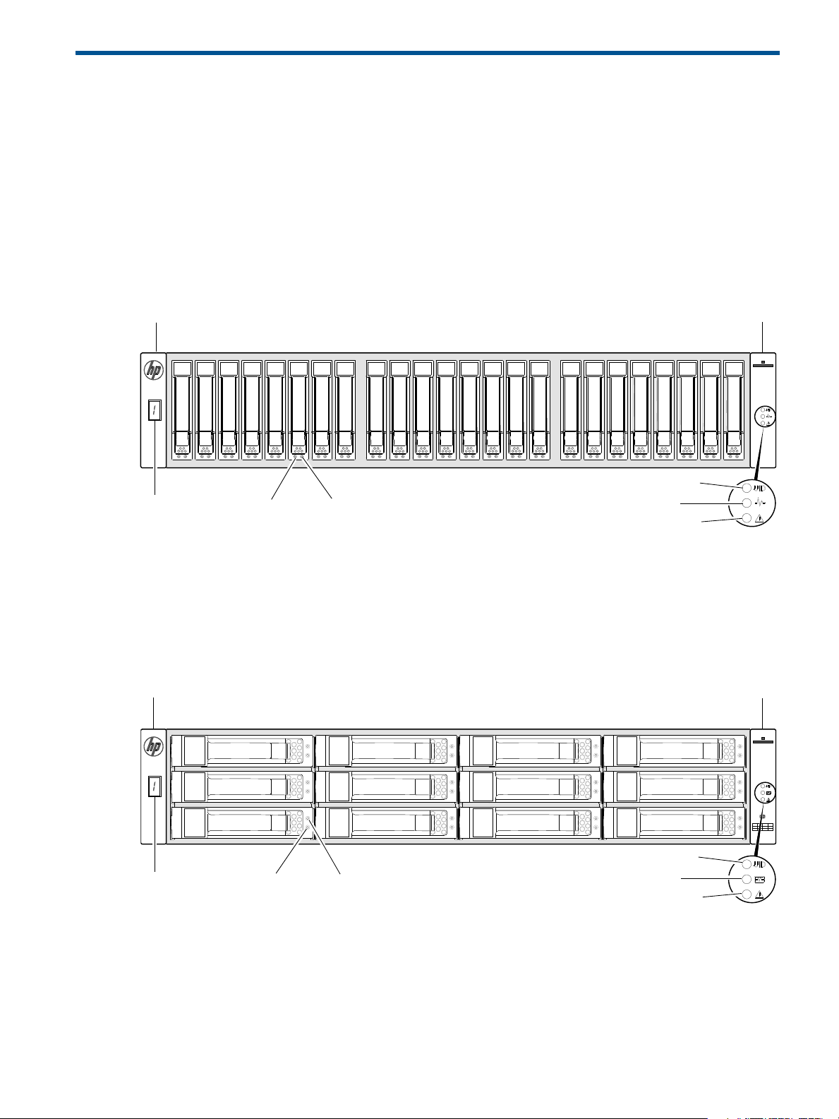
Front panel components
HP MSA 1040 models support small form factor (SFF) and large form factor (LFF) enclosures. The SFF
chassis, configured with 24 2.5" SFF disks, is used as a controller enclosure. The LFF chassis, configured
with 12 3.5" LFF disks, is used as either a controller enclosure or a drive enclosure.
Supported drive enclosures, used for adding storage, are available in LFF or SFF chassis. The MSA 2040
6 Gb 3.5" 12-drive enclosure is the large form factor drive enclosure used for storage expansion. The HP
D2700 6 Gb enclosure, configured with 25 2.5" SFF disks, is the small form factor drive enclosure used for
storage expansion. See "SFF drive enclosure" (page 16) for a description of the D2700.
MSA 1040 Array SFF enclosure
Left ear
1 Enclosure ID LED
2 Disk drive Online/Activity LED
3 Disk drive Fault/UID LED
Figure 1 MSA 1040 Array SFF enclosure: front panel
4 Unit Identification (UID) LED
5 Heartbeat LED
6 Fault ID LED
MSA 1040 Array LFF or supported 12-drive expansion enclosure
Left ear Right ear
Right ear
1 Enclosure ID LED
2 Disk drive Online/Activity LED
3 Disk drive Fault/UID LED
Figure 2 MSA 1040 Array LFF or supported 12-drive enclosure: front panel
4 Unit Identification (UID) LED
5 Heartbeat LED
6 Fault ID LED
Front panel components 13

Disk drives used in MSA 1040 enclosures
CACHE
LINK
ACT
6Gb/s
CACHE
LINK
ACT
6Gb/s
CLI
CLI
SERVICE−1SERVICE−2
CLI
CLI
SERVICE−1SERVICE−2
PORT 1 PORT 2
PORT 1 PORT 2
11
5
4
2
3
MSA 1040 controller enclosure
(rear panel locator illustration)
MSA 1040 enclosures support LFF/SFF Midline SAS, LFF/SFF Enterprise SAS, and SFF SSD disks. For
information about creating vdisks and adding spares using these different disk drive types, see the
HP MSA 1040 SMU Reference Guide and HPSEDDrivesReadThisFirst document.
Controller enclosure—rear panel layout
The diagram and table below display and identify important component items comprising the rear panel
layout of the MSA 1040 controller enclosure.
1 AC Power supplies
2 Controller module A (see face plate detail figures)
4 DC Power supply (2) — (DC model only)
5 DC Power switch
3 Controller module B (see face plate detail figures)
Figure 3 MSA 1040 Array: rear panel
A controller enclosure accommodates two power supply FRUs of the same type—either both AC or both
DC—within the two power supply slots (see two instances of callout 1 above). The controller enclosure
accommodates two controller module FRUs of the same type within the I/O module slots (see callouts 2
and 3 above).
IMPORTANT: If the MSA 1040 controller enclosure is configured with a single controller module, the
controller module must be installed in the upper slot (see callout 2 above), and an I/O module blank must
be installed in the lower slot (see callout 3 above). This configuration is required to allow sufficient air flow
through the enclosure during operation.
The diagrams with tables that immediately follow provide descriptions of the different controller modules
and power supply modules that can be installed into the rear panel of an MSA 1040 controller enclosure.
Showing controller modules and power supply modules separately from the enclosure provides improved
clarity in identifying the component items called out in the diagrams and described in the tables.
Descriptions are also provided for optional drive enclosures supported by MSA 1040 controller enclosures
for expanding storage capacity.
NOTE: MSA 1040 controller enclosures support hot-plug replacement of redundant controller modules,
fans, power supplies, and I/O modules. Hot-add of drive enclosures is also supported.
14 Components
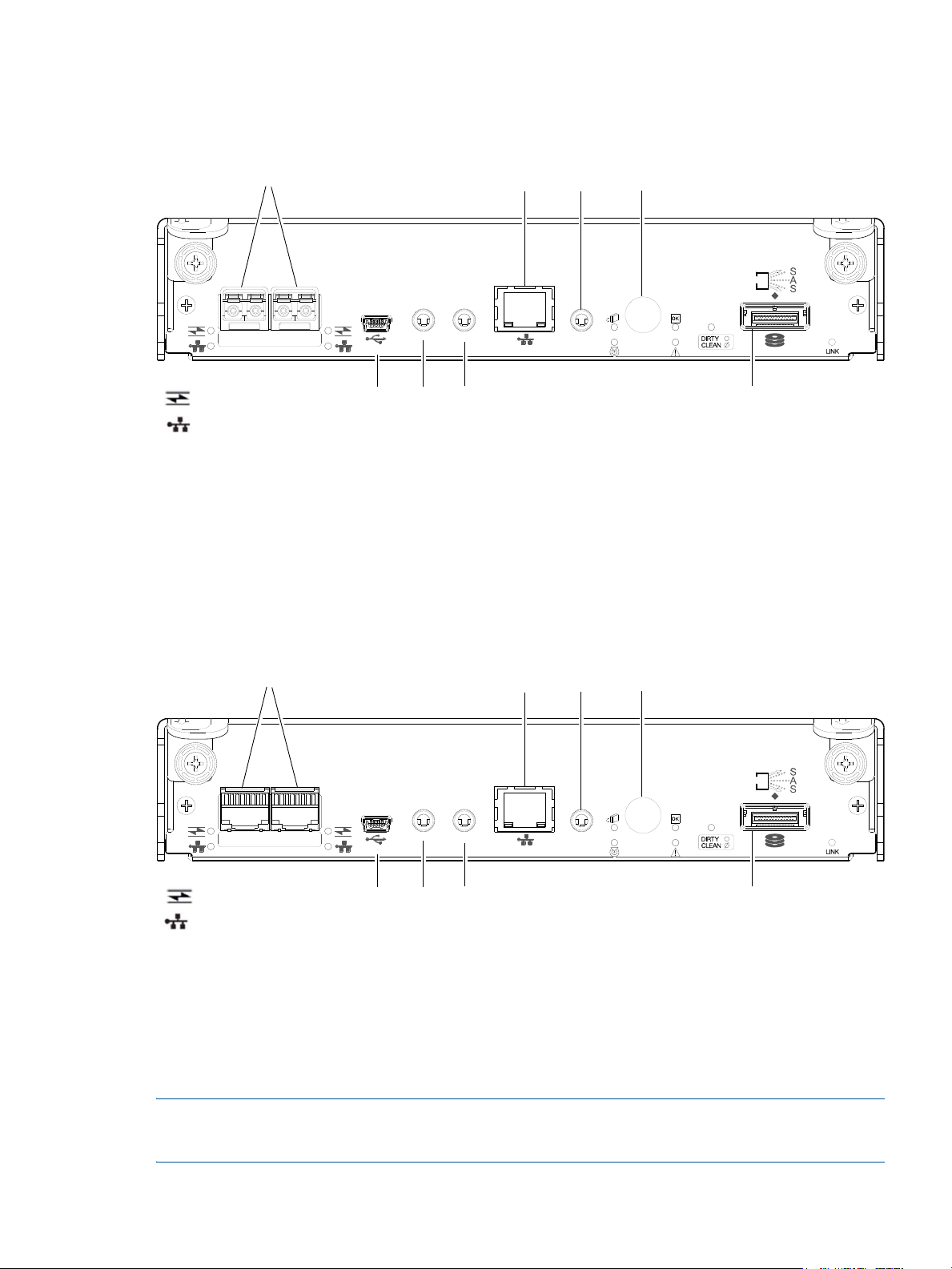
MSA 1040 controller module—rear panel components
CACHE
CLI
CLI
LINK
ACT
6Gb/s
SERVICE−1SERVICE−2
PORT 1 PORT 2
157
3 4
6
8
2
= FC LEDs
= 10GbE iSCSI LEDs
CACHE
CLI
CLI
LINK
ACT
6Gb/s
SERVICE−1SERVICE−2
PORT 1 PORT 2
= 1 Gb iSCSI LEDs (all host ports use 1 Gb RJ-45 SFPs in this figure)
157
3 4
6
8
2
= FC LEDs
Figure 4 shows host ports configured with either 8 Gb FC or 10GbE iSCSI SFPs. The SFPs look identical.
Refer to the LEDs that apply to the specific configuration of your host ports.
1 Host ports: used for host connection or replication
2 CLI port (USB - Type B)
3 Service port 2 (used by service personnel only)
4 Reserved for future use
5 Network port
6 Service port 1 (used by service personnel only)
7 Disabled button (used by engineering only)
(Sticker shown covering the opening)
8 SAS expansion port
Figure 4 MSA 1040 controller module face plate (FC or 10GbE iSCSI)
Figure 5 shows host ports configured with 1 Gb RJ-45 SFPs.
1 Host ports: used for host connection or replication
2 CLI port (USB - Type B)
3 Service port 2 (used by service personnel only)
4 Reserved for future use
5 Network port
Figure 5 MSA 1040 controller module face plate (1 Gb RJ-45)
NOTE: For information about host port configuration, see the “Configuring host ports” topic within the
HP MSA 1040 SMU Reference Guide or online help.
6 Service port 1 (used by service personnel only)
7 Disabled button (used by engineering only)
(Sticker shown covering the opening)
8 SAS expansion port
Controller enclosure—rear panel layout 15

IMPORTANT: See Connecting to the controller CLI port for information about enabling the controller
IN OUT
IN OUT
6Gb/s 6Gb/s
6Gb/s 6Gb/s
1457 16
2
3
enclosure USB Type - B CLI port for accessing the Command-line Interface via a telnet client.
Drive enclosures
Drive enclosure expansion modules attach to MSA 1040 controller modules via the mini-SAS expansion
port, allowing addition of disk drives to the system. MSA 1040 controller enclosures support adding the
6 Gb drive enclosures described below.
LFF drive enclosure — rear panel layout
MSA 1040 controllers support the MSA 2040 6 Gb 3.5" 12-drive enclosure shown below.
1 Power supplies (AC shown)
2 I/O module A
3 I/O module B
4 Disabled button (used by engineering only)
Figure 6 LFF 12-drive enclosure: rear panel
SFF drive enclosure
MSA 1040 controllers support the D2700 6 Gb drive enclosure for adding storage. For information about
this product, visit http://www.hp.com/support
provided in the MSA 1040 Quick Start Instructions and MSA 1040 Cable Configuration Guide.
Cache
To enable faster data access from disk storage, the following types of caching are performed:
• Write-back or write-through caching. The controller writes user data in the cache memory on the
module rather than directly to the drives. Later, when the storage system is either idle or aging—and
continuing to receive new I/O data—the controller writes the data to the drive array.
• Read-ahead caching. The controller detects sequential array access, reads ahead into the next
sequence of data, and stores the data in the read-ahead cache. Then, if the next read access is for
cached data, the controller immediately loads the data into the system memory, avoiding the latency of
a disk access.
5 Service port (used by service personnel only)
6 SAS In port
7 SAS Out port
. Pictorial representations of this drive enclosure are also
NOTE: See HP MSA 1040 SMU Reference Guide for more information about volume cache options.
Transportable CompactFlash
During a power loss or array controller failure, data stored in cache is saved off to non-volatile memory
(CompactFlash). The data is then written to disk after the issue is corrected. To protect against writing
incomplete data to disk, the image stored on the CompactFlash is verified before committing to disk.
16 Components

The CompactFlash card is located at the midplane-facing end of the controller module as shown below.
Do not remove
Used for cache recovery only
Controller module pictorial
CompactFlash card
(Midplane-facing rear view)
Figure 7 MSA 1040 CompactFlash card
In single-controller configurations, if the controller has failed or does not start, and the Cache Status LED is
on or blinking, the CompactFlash will need to be transported to a replacement controller to recover data
not flushed to disk (see "Controller failure in a single-controller configuration" (page 51) for more
information).
CAUTION: The CompactFlash card should only be removed for transportable purposes. To preserve the
existing data stored in the CompactFlash, you must transport the CompactFlash from the failed controller to
the replacement controller using a procedure outlined in the HP MSA Controller Module Replacement
Instructions shipped with the replacement controller module. Failure to use this procedure will result in the
loss of data stored in the cache module. The CompactFlash must stay with the same enclosure. If the
CompactFlash is used/installed in a different enclosure, data loss/data corruption will occur.
IMPORTANT: In dual controller configurations featuring one healthy partner controller, there is no need to
transport failed controller cache to a replacement controller because the cache is duplicated between the
controllers (subject to volume write optimization setting).
Supercapacitor pack
To protect RAID controller cache in case of power failure, MSA 1040 controllers are equipped with
supercapacitor technology, in conjunction with CompactFlash memory, built into each controller module to
provide extended cache memory backup time. The supercapacitor pack provides energy for backing up
unwritten data in the write cache to the CompactFlash in the event of a power failure. Unwritten data in
CompactFlash memory is automatically committed to disk media when power is restored. While the cache
is being maintained by the supercapacitor, the Cache Status LED flashes at a rate of 1/10 second on and
9/10 second off.
Upgrading to MSA 2040
For information about upgrading components for use with MSA controllers, refer to: Upgrading to the
HP MSA 2040.
Supercapacitor pack 17

18 Components
3Installing the enclosures
Installation checklist
The following table outlines the steps required to install the enclosures and initially configure the system. To
ensure a successful installation, perform the tasks in the order they are presented.
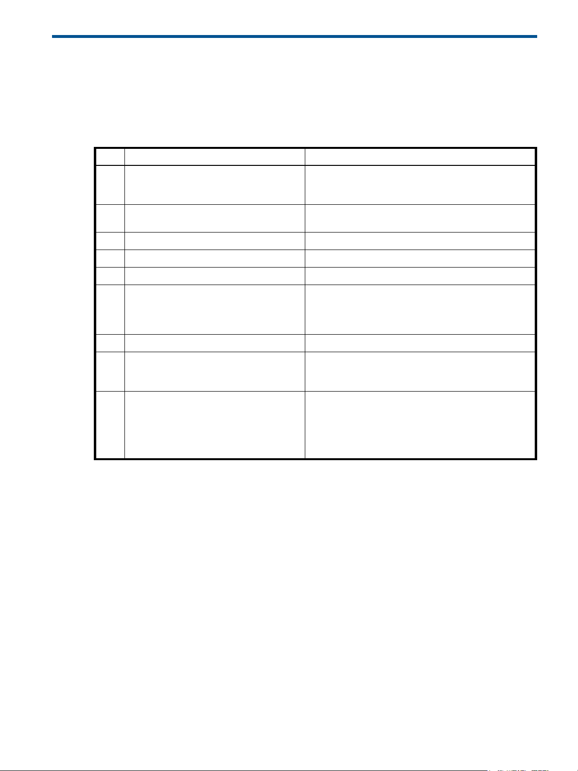
Table 1 Installation checklist
Step Task Where to find procedure
1. Install the controller enclosure and optional
drive enclosures in the rack, and attach ear
caps.
2. Connect the controller enclosure and LFF/SFF
drive enclosures.
3. Connect power cords. See the quick start instructions.
4. Test enclosure connections. See "Testing enclosure connections" (page 25).
5. Install required host software. See "Host system requirements" (page 29).
6. Connect data hosts. See "Connecting the enclosure to data hosts" (page 29).
7. Connect remote management hosts. See "Connecting remote management hosts" (page 32).
8. Obtain IP values and set management port IP
properties on the controller enclosure.
1
9. Perform initial configuration tasks
• Sign in to the web-based Storage
Management Utility (SMU).
• Initially configure and provision the
storage system using the SMU.
:
2
See the racking instructions poster.
See "Connecting controller and drive enclosures"
(page 19).
If using the optional Remote Snap feature, also see
"Connecting two storage systems to replicate volumes"
(page 32).
See "Obtaining IP values" (page 37).
See Connecting to the controller CLI port; with Linux and
Windows topics.
Topics below correspond to bullets at left:
See “Getting Started” in the HP MSA 1040 SMU Reference
Guide.
See “Configuring the System” and “Provisioning the
System” topics (SMU Reference Guide or online help).
1
The SMU is introduced in "Accessing the SMU" (page 43). See the SMU Reference Guide or online help for additional information.
2
If the systems are cabled for replication and licensed to use the Remote Snap feature, you can use the Replication Setup Wizard to
prepare to replicate an existing volume to another vdisk. See the SMU Reference Guide for additional information.
Connecting controller and drive enclosures
MSA 1040 controller enclosures support up to four enclosures (including the controller enclosure). You can
cable drive enclosures of the same type or of mixed LFF/SFF model type.
The firmware supports both straight-through and fault-tolerant SAS cabling. Fault-tolerant cabling allows
any drive enclosure to fail—or be removed—while maintaining access to other enclosures. Fault tolerance
and performance requirements determine whether to optimize the configuration for high availability or
high performance when cabling. MSA 1040 controller enclosures support 6 Gbit/s internal disk drive
speeds, together with 6 Gbit/s (SAS2.0) expander link speeds. When connecting multiple drive
enclosures, use fault-tolerant cabling to ensure the highest level of fault tolerance.
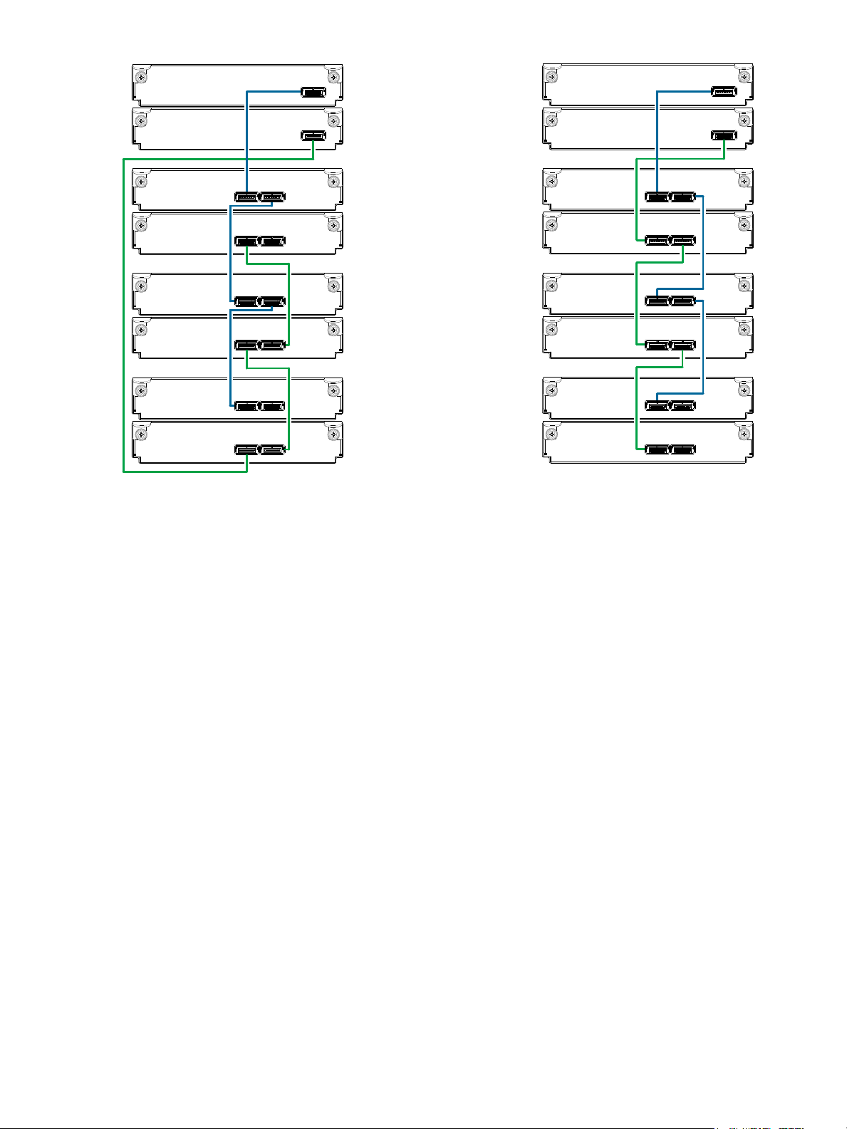
For example, the illustration on the left in Figure 10 (page 22) shows controller module 1A connected to
expansion module 2A, with a chain of connections cascading down (blue). Controller module 1B is
connected to the lower expansion module (4B) of the last drive enclosure, with connections moving in
the opposite direction (green).
Installation checklist 19

Connecting the MSA 1040 controller to the SFF drive enclosure
The SFF D2700 25-drive enclosure, supporting 6 Gb internal disk drive and expander link speeds, can be
attached to an MSA 1040 controller enclosure using supported mini-SAS to mini-SAS cables of 0.5 m
(1.64') to 2 m (6.56') length [see Figure 9 (page 21)].
Connecting the MSA 1040 controller to the LFF drive enclosure
The LFF MSA 1040 6 Gb 3.5"12-drive enclosure, supporting 6 Gb internal disk drive and expander link
speeds, can be attached to an MSA 1040 controller enclosure using supported mini-SAS to mini-SAS
cables of 0.5 m (1.64') to 2 m (6.56') length [see Figure 9 (page 21)].
Connecting the MSA 1040 controller to mixed model drive enclosures
MSA 1040 controllers support cabling of 6 Gb SAS link-rate LFF and SFF expansion modules—in mixed
model fashion—as shown in Figure 12 (page 24), and further described in the HP MSA 1040 Cable
Configuration Guide; the HP MSA 1040 Quick Start Instructions; QuickSpecs; and HP white papers (listed
below).
Cable requirements for MSA 1040 enclosures
IMPORTANT:
• When installing SAS cables to expansion modules, use only supported mini-SAS x4 cables with
SFF-8088 connectors supporting your 6 Gb application.
• Mini-SAS to mini-SAS 0.5 m (1.64') cables are used to connect cascaded enclosures in the rack.
• See QuickSpecs for information about which cables are provided with your MSA 1040 products.
http://www.hp.com/support/msa
• If additional or longer cables are required, they must be ordered separately (see relevant MSA 1040
QuickSpecs or P2000 G3 QuickSpecs for your products).
• The maximum expansion cable length allowed in any configuration is 2 m (6.56').
• Cables required, if not included, must be separately purchased.
• When adding more than two drive enclosures, you may need to purchase additional 1 m or 2 m
cables, depending upon number of enclosures and cabling method used:
Spanning 3 drive enclosures requires 1 m (3.28') cables.
• Se
e Quickspecs (link provided above) regarding information about cables supported for host connection:
• Qualified Fibre Channel SFP and cable options
• Qualified 10GbE iSCSI SFP and cable options
• Qualified 1 Gb RJ-45 SFP and cable options
1040/QuickSpecs
For additional information concerning cabling of MSA 1040 controllers and D2700 drive enclosures, visit:
h
ttp://www.hp.com/support/msa1040
Browse for the following reference documents:
• HP MSA 1040 Cable Configuration Guide
• HP Remote Snap technical white paper
• HP MSA 1040/2040 best practices
20 Installing the enclosures
NOTE: For clarity, the schematic illustrations of controller and expansion modules shown in this section
In Out
1B
1A
2A
2B
Controller A
IOM blank
P1 P2
Controller A
IOM blank
= LFF 12-drive enclosure
= SFF 25-drive enclosure
21
1
2
IOM blank
IOM blank
1B
1A
2A
2B
In Out
1B
1A
2A
2B
Controller A
Controller B
In Out
P1 P2
Controller A
Controller B
P1 P2
= LFF 12-drive enclosure
= SFF 25-drive enclosure
21
1
2
1B
1A
2A
2B
provide only relevant details such as expansion ports within the module face plate outline. For detailed
illustrations showing all components, see "Controller enclosure—rear panel layout" (page 14).
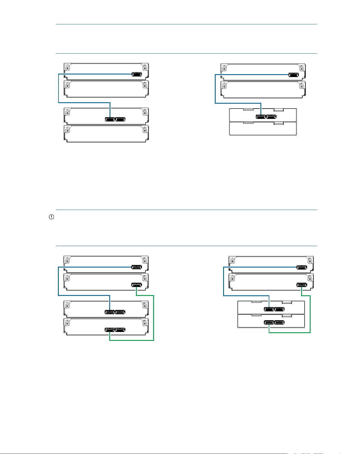
Figure 8 Cabling connections between the MSA 1040 controller and a single drive enclosure
The figure above shows examples of the MSA 1040 controller enclosure—equipped with a single controller
module—cabled to a single drive enclosure equipped with a single expansion module. The empty I/O
module slot in each of the enclosures is covered with an IOM blank to ensure sufficient air flow during
enclosure operation. The remaining illustrations in the section feature enclosures equipped with dual IOMs.
IMPORTANT: If the MSA 1040 controller enclosure is configured with a single controller module, the
controller module must be installed in the upper slot, and an I/O module blank must be installed in the
lower slot (shown above). This configuration is required to allow sufficient air flow through the enclosure
during operation.
Figure 9 Cabling connections between the MSA 1040 controller and a single drive enclosure
Connecting controller and drive enclosures 21
Controller A
Controller B
1A
1B
In
Out
2A
2B
3A
3B
4A
4B
In Out
In Out
In Out
In Out
In Out
Fault-tolerant cabling
Controller A
Controller B
In
Out
In Out
In Out
In Out
In Out
In Out
Straight-through cabling
1A
1B
2A
2B
3A
3B
4A
4B
Figure 10 Cabling connections between MSA 1040 controllers and LFF drive enclosures
The diagram at left (above) shows fault-tolerant cabling of a dual-controller enclosure cabled to MSA 2040
6 Gb 3.5" 12-drive enclosures featuring dual-expansion modules. Controller module 1A is connected to
expansion module 2A, with a chain of connections cascading down (blue). Controller module 1B is
connected to the lower expansion module (4B) of the last drive enclosure, with connections moving in the
opposite direction (green). Fault-tolerant cabling allows any drive enclosure to fail—or be removed—while
maintaining access to other enclosures.
The diagram at right (above) shows the same storage components connected using straight-through
cabling. Using this method, if a drive enclosure fails, the enclosures that follow the failed enclosure in the
chain are no longer accessible until the failed enclosure is repaired or replaced.
Both illustrations in Figure 10 show the maximum number of supported enclosures that can be cabled
together in an MSA 1040 system configuration: up to four enclosures (including the controller enclosure).
22 Installing the enclosures
P1
Controller A
Controller B
1A
1B
P2P1
P1
P1
P1
P1
2A
2B
3A
3B
4A
4B
P2
P2
P2
P2
P2
Fault-tolerant cabling
Straight-through cabling
P1
Controller A
Controller B
P2P1
P1
P1
P1
P1
P2
P2
P2
P2
P2
1A
1B
2A
2B
3A
3B
4A
4B
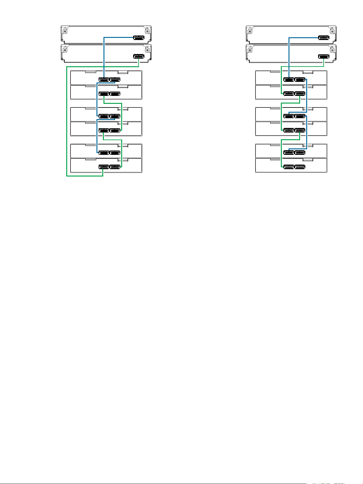
Figure 11 Cabling connections between MSA 1040 controllers and SFF drive enclosures
The figure above provides sample diagrams reflecting cabling of MSA 1040 controller enclosures and
D2700 6 Gb drive enclosures.
The diagram at left shows fault-tolerant cabling of a dual-controller enclosure and D2700 6 Gb drive
enclosures featuring dual-expansion modules. Controller module 1A is connected to expansion module
2A, with a chain of connections cascading down (blue). Controller module 1B is connected to the lower
expansion module (4B) of the last drive enclosure, with connections moving in the opposite direction
(green). Fault-tolerant cabling allows any drive enclosure to fail—or be removed—while maintaining
access to other enclosures.
The diagram at right shows the same storage components connected using straight-through cabling. Using
this method, if a drive enclosure fails, the enclosures that follow the failed enclosure in the chain are no
longer accessible until the failed enclosure is repaired or replaced.
Both illustrations in Figure 11 show the maximum number of supported enclosures that can be cabled
together in an MSA 1040 system configuration: up to four enclosures (including the controller enclosure).
Connecting controller and drive enclosures 23
1B
1A
Controller B
Controller A
3B
3A
4B
4A
P2
P2
P1
P1
2B
2A
Out
In
Out
In
Fault-tolerant cabling
1
2
2
= LFF 12-drive enclosure
1
= SFF 25-drive enclosure
2
Drive enclosure IOM face plate key:
Straight-through cabling
P2
P2
P1
P1
Controller B
Controller A
P2
P2
P1
P1
Out
In
Out
In
1
2
2
P2
P2
P1
P1
1B
1A
3B
3A
4B
4A
2B
2A
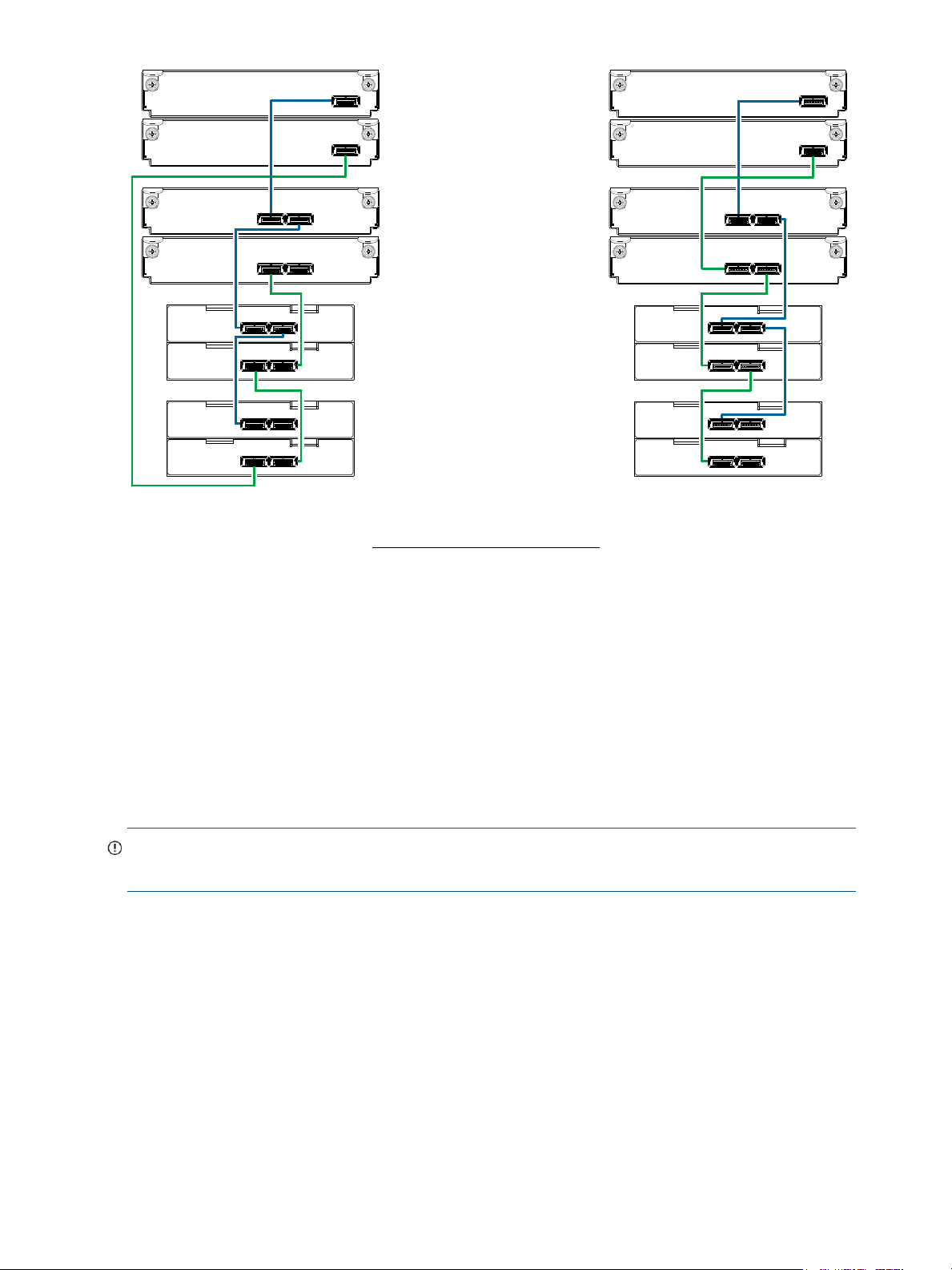
Figure 12 Cabling connections between MSA 1040 controllers and drive enclosures of mixed model type
The figure above provides sample diagrams reflecting cabling of MSA 1040 controller enclosures and
supported mixed model drive enclosures. In this example, the SFF drive enclosures follow the LFF drive
enclosures. Given that both drive enclosure models use 6 Gb SAS link-rate and SAS2.0 expanders, they
can be ordered in desired sequence within the array, following the controller enclosure.
MSA 1040 controller enclosures support up to four enclosures (including the controller enclosure) for
adding storage. Both illustrations in Figure 12 show the maximum number of supported enclosures that can
be cabled together in an MSA 1040 system configuration.
IMPORTANT: For comprehensive configuration options and associated illustrations, refer to the HP MSA
24 Installing the enclosures
1040 Cable Configuration Guide.

Testing enclosure connections
NOTE: Once the power-on sequence for enclosures succeeds, the storage system is ready to be
connected to hosts, as described in "Connecting the enclosure to data hosts" (page 29).
Powering on/powering off
Before powering on the enclosure for the first time:
• Install all disk drives in the enclosure so the controller can identify and configure them at power-up.
• Connect the cables and power cords to the enclosures as explained in the quick start instructions.
NOTE: MSA 1040 controller enclosures and drive enclosures do not have power switches (they are
switchless). They power on when connected to a power source, and they power off when disconnected.
• Generally, when powering up, make sure to power up the enclosures and associated data host in the
following order:
•Drive enclosures first
This ensures that disks in each drive enclosure have enough time to completely spin up before being
scanned by the controller modules within the controller enclosure.
While enclosures power up, their LEDs blink. After the LEDs stop blinking—
and back of the enclosure are amber—
detected. See "LED descriptions" (page 67) for descriptions of LED behavior.
• Controller enclosure next
Depending upon the number and type of disks in the system, it may take several minutes for the
system to become ready.
• Data host last (if powered down for maintenance purposes)
if no LEDs on the front
the power-on sequence is complete, and no faults have been
TIP: Generally, when powering off, you will reverse the order of steps used for powering on.
Power cycling procedures vary according to the type of power supply unit included with the enclosure. For
controller and drive enclosures configured with the switchless AC power supplies, refer to the procedure
described under AC power supply below. For procedures pertaining to a) controller enclosures configured
with DC power supplies, or b) previously installed drive enclosures featuring power switches, see "DC and
AC power supplies equipped with a power switch" (page 26).
IMPORTANT: See "Power cord requirements" (page 78) and QuickSpecs for more information about
power cords supported by MSA 1040 enclosures.
AC power supply
Enclosures equipped with switchless power supplies rely on the power cord for power cycling. Connecting
the cord from the power supply power cord connector to the appropriate power source facilitates power
on; whereas disconnecting the cord from the power source facilitates power off.
Testing enclosure connections 25

Figure 13 AC power supply
Power cord connect
Powe r
switch
Powe r
cable
connect
Power
switch
Power
cord
connect
DC power supply unit Legacy AC power supply unit
To power on the system:
1. Obtain a suitable AC power cord for each AC power supply that will connect to a power source.
2. Plug the power cord into the power cord connector on the back of the drive enclosure (see Figure 13).
Plug the other end of the power cord into the rack power source. Wait several seconds to allow the
disks to spin up.
Repeat this sequence for each power supply within each drive enclosure.
3. Plug the power cord into the power cord connector on the back of the controller enclosure (see
Figure 13). Plug the other end of the power cord into the rack power source.
Repeat the sequence for the controller enclosure’s other switchless power supply.
To power off the system:
1. Stop all I/O from hosts to the system [see "Stopping I/O" (page 47)].
2. Shut down both controllers using either method described below:
• Use the SMU (Storage Management Utility) to shut down both controllers, as described in the online
help and web-posted HP MSA 1040 SMU Reference Guide.
Proceed to step 3.
• Use the command-line interface (CLI) to shut down both controllers, as described in the HP MSA
1040 CLI Reference Guide.
3. Disconnect the power cord male plug from the power source.
4. Disconnect the power cord female plug from the power cord connector on the power supply.
NOTE: Power cycling for enclosures equipped with a power switch is described below.
DC and AC power supplies equipped with a power switch
DC power supplies and legacy AC power supplies are shown below. Each model has a power switch.
Figure 14 DC and AC power supplies with power switch
26 Installing the enclosures
Loading...