


 Loading...
HP ProLiant ML350 G6 Server
User Guide
Abstract
This document is for the person who installs, administers, and troubleshoots servers and storage systems. HP assumes you are qualified in the servicing of computer equipment and trained in recognizing hazards in products with hazardous energy levels.
Part Number: 513503-003
February 2011
Edition: 3
© Copyright 2009, 2011 Hewlett-Packard Development Company, L.P.
The information contained herein is subject to change without notice. The only warranties for HP products and services are set forth in the express warranty statements accompanying such products and services. Nothing herein should be construed as constituting an additional warranty. HP shall not be liable for technical or editorial errors or omissions contained herein.
Microsoft, Windows, and Windows Server are U.S. registered trademarks of Microsoft Corporation.

Contents |
|
Component identification............................................................................................................... |
7 |
Front panel components ............................................................................................................................. |
7 |
Front panel LEDs and buttons ...................................................................................................................... |
8 |
Rear panel components.............................................................................................................................. |
9 |
Rear panel LEDs and buttons..................................................................................................................... |
10 |
System board components........................................................................................................................ |
11 |
System board LEDs ........................................................................................................................ |
13 |
NMI functionality........................................................................................................................... |
14 |
System maintenance switch............................................................................................................. |
14 |
SAS/SATA device numbers ...................................................................................................................... |
15 |
SAS and SATA hard drive LEDs................................................................................................................. |
16 |
SAS and SATA hard drive LED combinations .............................................................................................. |
17 |
Battery pack LEDs.................................................................................................................................... |
18 |
FBWC module LEDs................................................................................................................................. |
19 |
Fan locations and configurations ............................................................................................................... |
20 |
Operations................................................................................................................................. |
24 |
Power up the server ................................................................................................................................. |
24 |
Power down the server............................................................................................................................. |
24 |
Extend the server from the rack ................................................................................................................. |
24 |
Remove the server from the rack................................................................................................................ |
25 |
Access the server rear panel (rack model)................................................................................................... |
25 |
Open or remove the tower bezel............................................................................................................... |
25 |
Remove the access panel.......................................................................................................................... |
26 |
Install the access panel............................................................................................................................. |
27 |
Remove the media bay blank.................................................................................................................... |
27 |
Remove the large redundant fan air baffle .................................................................................................. |
27 |
Remove the DIMM baffle .......................................................................................................................... |
28 |
Remove a fan blank................................................................................................................................. |
29 |
Setup......................................................................................................................................... |
30 |
Optional installation services .................................................................................................................... |
30 |
Optimum environment.............................................................................................................................. |
30 |
Space and airflow requirements ...................................................................................................... |
30 |
Temperature requirements............................................................................................................... |
31 |
Power requirements ....................................................................................................................... |
32 |
Electrical grounding requirements .................................................................................................... |
32 |
Rack planning resources........................................................................................................................... |
32 |
Rack warnings ........................................................................................................................................ |
33 |
Contents of the tower server shipping carton............................................................................................... |
33 |
Contents of the rack server shipping carton................................................................................................. |
33 |
Installing hardware options....................................................................................................................... |
34 |
Setting up a tower server.......................................................................................................................... |
34 |
Installing the server into the rack................................................................................................................ |
35 |
Powering up and configuring the server ..................................................................................................... |
36 |
Installing the operating system................................................................................................................... |
36 |
Registering the server............................................................................................................................... |
36 |
Contents |
3 |
Hardware options installation....................................................................................................... |
37 |
Introduction ............................................................................................................................................ |
37 |
Processor option...................................................................................................................................... |
37 |
Memory options ...................................................................................................................................... |
44 |
Memory subsystem architecture ....................................................................................................... |
44 |
Single-, dual-, and quad-rank DIMMs ............................................................................................... |
45 |
DIMM identification ....................................................................................................................... |
45 |
Memory configurations................................................................................................................... |
46 |
General DIMM slot population guidelines ......................................................................................... |
48 |
Installing DIMMs ........................................................................................................................... |
51 |
SAS or SATA hard drive option................................................................................................................. |
52 |
Hard drive cage options .......................................................................................................................... |
54 |
Installing a hard drive expansion cage power cable .......................................................................... |
54 |
Eight-bay SFF drive cage option ...................................................................................................... |
57 |
Two-bay LFF drive cage option ........................................................................................................ |
59 |
Removable media device options .............................................................................................................. |
62 |
Identifying guide screws ................................................................................................................. |
62 |
Installing a half-height or full-height media device .............................................................................. |
62 |
Installing the full-height media device shipping screw ......................................................................... |
64 |
Redundant fan assembly option................................................................................................................. |
65 |
Redundant hot-plug power supply option .................................................................................................... |
66 |
Power supply configuration............................................................................................................. |
67 |
Installing the redundant hot-plug power supply option ........................................................................ |
67 |
Expansion board options.......................................................................................................................... |
69 |
Removing the expansion slot cover .................................................................................................. |
69 |
Installing an expansion board ......................................................................................................... |
70 |
PCI-X expansion cage option .................................................................................................................... |
71 |
Battery-backed write cache option ............................................................................................................. |
78 |
FBWC module and capacitor pack option .................................................................................................. |
80 |
150W PCIe video/graphics controller power cable option........................................................................... |
82 |
HP Trusted Platform Module option ............................................................................................................ |
84 |
Installing the Trusted Platform Module board ..................................................................................... |
85 |
Retaining the recovery key/password .............................................................................................. |
86 |
Enabling the Trusted Platform Module............................................................................................... |
87 |
Tower-to-rack conversion option ................................................................................................................ |
87 |
Configuration and utilities ............................................................................................................ |
91 |
Configuration tools .................................................................................................................................. |
91 |
SmartStart software........................................................................................................................ |
91 |
HP ROM-Based Setup Utility............................................................................................................ |
92 |
Array Configuration Utility .............................................................................................................. |
94 |
Option ROM Configuration for Arrays ............................................................................................. |
95 |
Re-entering the server serial number and product ID ........................................................................... |
95 |
Management tools................................................................................................................................... |
96 |
Automatic Server Recovery ............................................................................................................. |
96 |
ROMPaq utility.............................................................................................................................. |
96 |
Integrated Lights-Out 2 technology................................................................................................... |
96 |
Erase Utility .................................................................................................................................. |
97 |
Redundant ROM support ................................................................................................................ |
97 |
USB support and functionality ......................................................................................................... |
97 |
Internal SD support ........................................................................................................................ |
98 |
Diagnostic tools ...................................................................................................................................... |
98 |
HP Insight Diagnostics.................................................................................................................... |
98 |
Contents |
4 |
HP Insight Diagnostics survey functionality ........................................................................................ |
98 |
Integrated Management Log ........................................................................................................... |
99 |
Remote support and analysis tools ............................................................................................................. |
99 |
HP Insight Remote Support software ................................................................................................. |
99 |
Keeping the system current ..................................................................................................................... |
100 |
Drivers ....................................................................................................................................... |
100 |
ProLiant Support Packs ................................................................................................................. |
100 |
Operating System Version Support ................................................................................................ |
100 |
Change control and proactive notification ...................................................................................... |
100 |
Care Pack .................................................................................................................................. |
101 |
Troubleshooting ........................................................................................................................ |
102 |
Troubleshooting resources ...................................................................................................................... |
102 |
Pre-diagnostic steps ............................................................................................................................... |
102 |
Important safety information.......................................................................................................... |
102 |
Symptom information ................................................................................................................... |
104 |
Prepare the server for diagnosis .................................................................................................... |
104 |
Loose connections ................................................................................................................................. |
106 |
Service notifications............................................................................................................................... |
107 |
Server health LEDs ................................................................................................................................. |
107 |
Troubleshooting flowcharts ..................................................................................................................... |
107 |
Start diagnosis flowchart .............................................................................................................. |
107 |
General diagnosis flowchart ......................................................................................................... |
108 |
Server power-on problems flowchart .............................................................................................. |
110 |
POST problems flowchart ............................................................................................................. |
113 |
OS boot problems flowchart ......................................................................................................... |
115 |
Server fault indications flowchart ................................................................................................... |
116 |
POST error messages and beep codes ..................................................................................................... |
118 |
Battery replacement .................................................................................................................. |
120 |
Regulatory compliance notices ................................................................................................... |
121 |
Regulatory compliance identification numbers ........................................................................................... |
121 |
Federal Communications Commission notice............................................................................................. |
121 |
FCC rating label.......................................................................................................................... |
121 |
Class A equipment....................................................................................................................... |
121 |
Class B equipment ....................................................................................................................... |
121 |
Declaration of conformity for products marked with the FCC logo, United States only..................................... |
122 |
Modifications........................................................................................................................................ |
122 |
Cables................................................................................................................................................. |
122 |
Canadian notice (Avis Canadien)............................................................................................................ |
122 |
European Union regulatory notice ........................................................................................................... |
123 |
Disposal of waste equipment by users in private households in the European Union ....................................... |
123 |
Japanese notice .................................................................................................................................... |
124 |
BSMI notice .......................................................................................................................................... |
124 |
Korean notice ....................................................................................................................................... |
124 |
Chinese notice ...................................................................................................................................... |
125 |
Laser compliance .................................................................................................................................. |
125 |
Battery replacement notice...................................................................................................................... |
125 |
Taiwan battery recycling notice............................................................................................................... |
126 |
Power cord statement for Japan............................................................................................................... |
126 |
Acoustics statement for Germany (Geräuschemission) ................................................................................ |
126 |
Electrostatic discharge............................................................................................................... |
127 |
Preventing electrostatic discharge ............................................................................................................ |
127 |
|
Contents 5 |
Grounding methods to prevent electrostatic discharge |
................................................................................ 127 |
Server specifications ................................................................................................................. |
128 |
Environmental specifications ................................................................................................................... |
128 |
Mechanical specifications ...................................................................................................................... |
128 |
Power supply specifications .................................................................................................................... |
128 |
Technical support...................................................................................................................... |
131 |
Before you contact HP............................................................................................................................ |
131 |
HP contact information........................................................................................................................... |
131 |
Customer Self Repair ............................................................................................................................. |
131 |
Acronyms and abbreviations...................................................................................................... |
139 |
Index....................................................................................................................................... |
142 |
Contents 6

Component identification
Front panel components
Item |
Description |
|
|
1 |
Power On/Standby button |
2 |
UID button |
3 |
USB connectors (2) |
4 |
Hot-plug hard drive bays (8-bay SFF drive cage model) |
5 |
Removable media bays |
6 |
Optical drive |
Component identification 7

Front panel LEDs and buttons
Item |
Description |
Status |
|
|
|
1 |
System power LED |
Green = Power on |
|
|
Flashing green = Waiting for power due to group power capping |
|
|
Amber = System in standby, but power still applied |
|
|
Off = Power cord not attached or power supply failure |
|
|
|
2 |
Health LED |
Green = Normal |
|
|
Amber = System degraded. To identify the component in a degraded |
|
|
state, see the system board LEDs (on page 13). |
|
|
Red = System critical. To identify the component in a critical state, see |
|
|
the system board LEDs (on page 13). |
|
|
Off = Normal (when in standby mode) |
|
|
|
3 |
Power cap LED |
Green = Power cap configured |
|
|
Flashing amber = Power cap exceeded |
|
|
Off = Server in standby or power cap disabled |
|
|
|
4 |
NIC 1 activity LED |
Green = Network link |
|
|
Flashing = Network link and activity |
|
|
Off = No link to network. If power is off, view status on the rear panel |
|
|
RJ45 LEDs ("Rear panel LEDs and buttons" on page 10). |
|
|
|
5 |
NIC 2 activity LED |
Green = Network link |
|
|
Flashing = Network link and activity |
|
|
Off = No link to network. If power is off, view status on the rear panel |
|
|
RJ45 LEDs ("Rear panel LEDs and buttons" on page 10). |
|
|
|
6 |
UID LED |
Blue = Activated |
|
|
Flashing = System managed remotely |
|
|
Off = Deactivated |
|
|
|
Component identification 8

Rear panel components
Item |
Description |
|
|
1 |
Power supply bay 2 |
2 |
Keyboard connector |
3 |
Power supply bay 1 (populated) |
4 |
Video connector |
5 |
USB connectors (2) |
6 |
RJ-45 Ethernet connectors (2) |
7 |
Slot 1 PCIe2 x8 (4, 2, 1)¹ |
8 |
Slot 2 PCIe2 x8 (4, 2, 1)² |
9 |
Slot 3 PCIe2 x8 (8, 4, 2, 1)³ |
10 |
Slot 4 PCIe2 x16 (8, 4, 2, 1) 75W +EXT 75W4 |
11 |
Slot 5 PCIe2 x8 (4, 2, 1) |
12 |
Slot 6 PCIe2 x8 (4, 2, 1) |
13 |
RJ-45 Ethernet connector (dedicated iLO 2 management) |
14 |
Serial connector |
15 |
Mouse connector |
¹The SAS expander and the HP NC522SFP Dual Port 10GbE Server Adapter are not supported in slot 1. ²HP recommends the SAS expander is installed in slot 2.
³The HP NC522SFP Dual Port 10GbE Server Adapter is only supported in slot 3.
Component identification 9

4To support options beyond 75W, install the 150W PCIe video/graphics controller power cable option (on page 82).
Rear panel LEDs and buttons
Item |
Description |
Status |
|
|
|
1 |
Power supply 2 LED |
Green = Power supply is on and functioning. |
|
|
Off = AC power is not available or AC power supply has failed. |
|
|
|
2 |
UID LED |
Blue = Activated |
|
|
Flashing blue = System managed remotely |
|
|
Off = Deactivated |
|
|
|
3 |
Power supply 1 LED |
Green = Power supply is on and functioning. |
|
|
Off = AC power is not available or AC power supply has failed. |
4 |
iLO 2 link LED |
Green = Linked to network |
|
|
Off = Not linked to network |
5 |
iLO 2 activity LED |
Green or flashing = Network activity |
|
|
Off = No network activity |
|
|
|
6 |
NIC 2 link LED |
Green = Linked to network |
|
|
Off = Not linked to network |
|
|
|
7 |
NIC 2 activity LED |
Green or flashing = Network activity |
|
|
Off = No network activity |
Component identification 10
Item |
Description |
Status |
|
|
|
8 |
NIC 1 link LED |
Green = Linked to network |
|
|
Off = Not linked to network |
9 |
NIC 1 activity LED |
Green or flashing = Network activity |
|
|
Off = No network activity |
|
|
|
System board components
Item |
Description |
|
|
1 |
Processor 1 DIMM slots |
2 |
Power supply backplane connector |
3 |
Processor socket 2 |
4 |
System fan 4 connector |
5 |
System power connectors |
6 |
Processor 2 DIMM slots |
7 |
System fan 3 connector |
8 |
SD card slot (non-hot-plug) |
9 |
System maintenance switch |
10 |
Front panel LED board connector |
11 |
SAS connector B |
12 |
SAS connector A |
13 |
HP Smart Array P410i memory connector |
Component identification 11

Item |
Description |
|
|
|
|
|
|
14 |
TPM connector |
|
|
15 |
SATA connectors (6) |
||
16 |
Slot 1 PCIe2 x8 |
(4, 2, 1)¹ |
|
17 |
Slot 2 PCIe2 x8 |
(4, 2, 1)² |
|
18 |
10Gb sideband connector (MII 24-pin) |
||
19 |
Slot 3 |
PCIe2 x8 |
(8, 4, 2, 1)³ |
20 |
Slot 4 |
PCIe2 x16 (8, 4, 2, 1) 75W +EXT 75W4 |
|
21 |
Slot 5 |
PCIe2 x8 |
(4, 2, 1) |
22 |
Slot 6 |
PCIe2 x8 |
(4, 2, 1) |
23 |
Internal USB connector |
||
24 |
Internal USB tape connector |
||
25 |
System battery |
|
|
26 |
System fan 2 connector |
||
27 |
Processor socket 1 |
||
28 |
System fan 1 connector |
||
¹The SAS expander and the HP NC522SFP Dual Port 10GbE Server Adapter are not supported in slot 1. ²HP recommends the SAS expander is installed in slot 2.
³The HP NC522SFP Dual Port 10GbE Server Adapter is only supported in slot 3.
4To support options beyond 75W, install the 150W PCIe video/graphics controller power cable option (on page 82).
Component identification 12

System board LEDs
Item |
Description |
Status |
|
|
|
1 |
Power supply 1 |
Amber = No AC power or failed power supply |
|
|
Off = Power supply is on and functioning. |
|
|
|
2 |
Power supply 2 |
Amber = No AC power or failed power supply |
|
|
Off = Power supply is on and functioning. |
|
|
|
3 |
Processor 2 |
Amber = Processor 2 failed. |
|
|
Off = Processor 2 is functioning. |
4 |
System fan 4 |
Amber = Fan is missing or has failed. |
|
|
Off = Fan is functioning. |
5 |
AMP status |
Green = AMP mode is enabled. |
|
|
Amber = Failover has occurred, or the |
|
|
configuration is not valid. |
|
|
Off = AMP mode is disabled. |
|
|
|
6 |
Processor 2 DIMMs |
Amber = An error has occurred. |
|
|
Off = Normal operation |
7 |
System fan 3 |
Amber = Fan is missing or has failed. |
|
|
Off = Fan is functioning. |
|
|
|
8 |
Overtemperature |
Amber = System temperature threshold exceeded |
|
|
Off = Normal operation |
|
|
|
9 |
System fan 2 |
Amber = Fan is missing or has failed. |
|
|
Off = Fan is functioning. |
10 |
Processor 1 |
Amber = Processor 1 failed. |
|
|
Off = Processor 1 is functioning. |
Component identification 13
Item |
Description |
Status |
|
|
|
11 |
System fan 1 |
Amber = Fan is missing or has failed. |
|
|
Off = Fan is functioning. |
|
|
|
12 |
Processor 1 DIMMs |
Amber = An error has occurred. |
|
|
Off = Normal operation |
|
|
|
NMI functionality
An NMI crash dump enables administrators to create crash dump files when a system is hung and not responding to traditional debug mechanisms.
Crash dump log analysis is an essential part of diagnosing reliability problems, such as hangs in operating systems, device drivers, and applications. Many crashes freeze a system, and the only available action for administrators is to cycle the system power. Resetting the system erases any information that could support problem analysis, but the NMI feature preserves that information by performing a memory dump before a hard reset.
To force the OS to invoke the NMI handler and generate a crash dump log, the administrator can do any of the following:
•Short the NMI jumper pins
•Press the NMI switch
•Use the iLO Virtual NMI feature
For additional information, see the whitepaper on the HP website (http://h20000.www2.hp.com/bc/docs/support/SupportManual/c00797875/c00797875.pdf).
System maintenance switch
Position |
Default |
Function |
|
|
|
S1 |
Off |
Off = iLO 2 security is enabled. |
|
|
On = iLO 2 security is disabled. |
|
|
|
S2 |
Off |
Off = System configuration can be |
|
|
changed. |
|
|
On = System configuration is locked. |
|
|
|
S3 |
Off |
Reserved |
S4 |
Off |
Reserved |
S5 |
Off |
Off = Power-on password is enabled. |
|
|
On = Power-on password is disabled. |
S6 |
Off |
Off = No function |
|
|
On = Clear NVRAM |
|
|
|
S7 |
— |
Reserved |
S8 |
— |
Reserved |
S9 |
— |
Reserved |
S10 |
— |
Reserved |
When the system maintenance switch position 6 is set to the On position, the system is prepared to erase all system configuration settings from both CMOS and NVRAM.
Component identification 14

CAUTION: Clearing CMOS and/or NVRAM deletes configuration information. Be sure to properly configure the server or data loss could occur.
SAS/SATA device numbers
•SFF configuration with an optional SAS expander
•SFF configuration with a second SAS controller
Component identification 15

•LFF configuration
SAS and SATA hard drive LEDs
Item Description
1Fault/UID LED (amber/blue)
2Online LED (green)
Component identification 16
SAS and SATA hard drive LED combinations
Online/activity |
Fault/UID LED |
Interpretation |
LED (green) |
(amber/blue) |
|
|
|
|
On, off, or flashing |
Alternating amber |
The drive has failed, or a predictive failure alert has been received |
|
and blue |
for this drive; it also has been selected by a management |
|
|
application. |
|
|
|
On, off, or flashing |
Steadily blue |
The drive is operating normally, and it has been selected by a |
|
|
management application. |
|
|
|
On |
Amber, flashing |
A predictive failure alert has been received for this drive. |
|
regularly (1 Hz) |
Replace the drive as soon as possible. |
On |
Off |
The drive is online, but it is not active currently. |
Flashing regularly |
Amber, flashing |
Do not remove the drive. Removing a drive may terminate the |
(1 Hz) |
regularly (1 Hz) |
current operation and cause data loss. |
|
|
The drive is part of an array that is undergoing capacity expansion |
|
|
or stripe migration, but a predictive failure alert has been received |
|
|
for this drive. To minimize the risk of data loss, do not replace the |
|
|
drive until the expansion or migration is complete. |
|
|
|
Flashing regularly |
Off |
Do not remove the drive. Removing a drive may terminate the |
(1 Hz) |
|
current operation and cause data loss. |
|
|
The drive is rebuilding, erasing, or it is part of an array that is |
|
|
undergoing capacity expansion or stripe migration. |
|
|
|
Flashing irregularly |
Amber, flashing |
The drive is active, but a predictive failure alert has been received |
|
regularly (1 Hz) |
for this drive. Replace the drive as soon as possible. |
Flashing irregularly |
Off |
The drive is active, and it is operating normally. |
Off |
Steadily amber |
A critical fault condition has been identified for this drive, and the |
|
|
controller has placed it offline. Replace the drive as soon as |
|
|
possible. |
|
|
|
Off |
Amber, flashing |
A predictive failure alert has been received for this drive. Replace |
|
regularly (1 Hz) |
the drive as soon as possible. |
|
|
|
Off |
Off |
The drive is offline, a spare, or not configured as part of an array. |
Component identification 17

Battery pack LEDs
Item ID |
Color |
Description |
|
|
|
1 |
Green |
System Power LED. This LED glows steadily when the system |
|
|
is powered up and 12 V system power is available. This |
|
|
power supply is used to maintain the battery charge and |
|
|
provide supplementary power to the cache microcontroller. |
|
|
|
2 |
Green |
Auxiliary Power LED. This LED glows steadily when 3.3V |
|
|
auxiliary voltage is detected. The auxiliary voltage is used |
|
|
to preserve BBWC data and is available any time that the |
|
|
system power cords are connected to a power supply. |
|
|
|
3 |
Amber |
Battery Health LED. To interpret the illumination patterns of |
|
|
this LED, see the following table. |
|
|
|
4 |
Green |
BBWC Status LED. To interpret the illumination patterns of |
|
|
this LED, see the following table. |
|
|
|
LED3 pattern |
LED4 pattern |
Interpretation |
|
|
|
— |
One blink every |
The system is powered down, and the cache contains data that has not |
|
two seconds |
yet been written to the drives. Restore system power as soon as |
|
|
possible to prevent data loss. |
|
|
Data preservation time is extended any time that 3.3 V auxiliary |
|
|
power is available, as indicated by LED 2. In the absence of auxiliary |
|
|
power, battery power alone preserves the data. A fully-charged |
|
|
battery can normally preserve data for at least two days. |
|
|
The battery lifetime also depends on the cache module size. For further |
|
|
information, refer to the controller QuickSpecs on the HP website |
|
|
(http://www.hp.com). |
|
|
|
— |
Double blink, then |
The cache microcontroller is waiting for the host controller to |
|
pause |
communicate. |
Component identification 18

LED3 pattern |
LED4 pattern |
Interpretation |
|
|
|
— |
One blink per |
The battery pack is below the minimum charge level and is being |
|
second |
charged. Features that require a battery (such as write cache, capacity |
|
|
expansion, stripe size migration, and RAID migration) are temporarily |
|
|
unavailable until charging is complete. The recharge process takes |
|
|
between 15 minutes and two hours, depending on the initial capacity |
|
|
of the battery. |
|
|
|
— |
Steady glow |
The battery pack is fully charged, and posted write data is stored in the |
|
|
cache. |
|
|
|
— |
Off |
The battery pack is fully charged, and there is no posted write data in |
|
|
the cache. |
One blink per |
One blink per |
An alternating green and amber blink pattern indicates that the cache |
second |
second |
microcontroller is executing from within its boot loader and receiving |
|
|
new flash code from the host controller. |
Steady glow |
— |
There is a short circuit across the battery terminals or within the battery |
|
|
pack. BBWC features are disabled until the battery pack is replaced. |
|
|
The life expectancy of a battery pack is typically more than three |
|
|
years. |
|
|
|
One blink per |
— |
There is an open circuit across the battery terminals or within the |
second |
|
battery pack. BBWC features are disabled until the battery pack is |
|
|
replaced. The life expectancy of a battery pack is typically more than |
|
|
three years. |
|
|
|
FBWC module LEDs
The FBWC module has two single-color LEDs (green and amber). The LEDs are duplicated on the reverse side of the cache module to facilitate status viewing.
Green LED |
Amber LED |
Interpretation |
|
|
|
Off |
On |
A backup is in progress. |
Flashing (1 Hz) |
On |
A restore is in progress. |
Flashing (1 Hz) |
Off |
The capacitor pack is charging. |
On |
Off |
The capacitor pack has completed charging. |
Component identification 19

Green LED |
Amber LED |
Interpretation |
|
|
|
Flashing (2 Hz) |
Flashing (2 Hz) |
One of the following conditions exists: |
Alternating with |
Alternating with |
• The charging process has timed out. |
amber LED |
green LED |
• The capacitor pack is not connected. |
|
|
|
On |
On |
The flash code image failed to load. |
Off |
Off |
The flash code is corrupt. |
Fan locations and configurations
CAUTION: To maintain proper cooling, all fan bays must be populated with a fan or a fan blank.
•Fan locations
Item |
Description |
|
|
1 |
Rear fan 1 |
2 |
Rear fan 2 |
3 |
Front fan 3 |
4 |
Front fan 4 |
Component identification 20
•Single-processor, standard fan configuration
Item |
Description |
|
|
1 |
Rear fan 1 |
|
|
2 |
Rear fan 2 |
|
|
3 |
Front fan 3 |
|
|
4 |
Processor 1 |
|
|
5 |
DIMM baffle |
|
|
•Single-processor, redundant fan configuration
Item |
Description |
|
|
1 |
Rear fan 1 |
2 |
Rear fan 2 |
Component identification 21

Item |
Description |
|
|
3 |
Front fan 3 |
4 |
Front fan 4 |
5 |
Processor 1 |
6 |
DIMM baffle |
7 |
Large redundant fan air baffle |
•Dual-processor, non-redundant fan configuration
Item |
Description |
|
|
1 |
Rear fan 1 |
2 |
Rear fan 2 |
3 |
Front fan 3 |
4 |
Processor 1 |
5 |
Processor 2 |
6 |
DIMM baffles |
Component identification 22
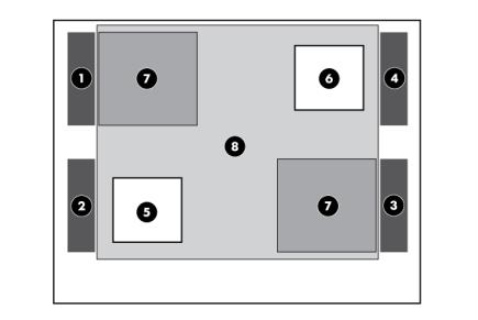
•Dual-processor, redundant fan configuration
Item |
Description |
|
|
1 |
Rear fan 1 |
2 |
Rear fan 2 |
3 |
Front fan 3 |
4 |
Front fan 4 |
5 |
Processor 1 |
6 |
Processor 2 |
7 |
DIMM baffles |
8 |
Large redundant fan air baffle |
Component identification 23

Operations
Power up the server
To power up the server, press the Power On/Standby button.
To determine status, see "Front panel LEDs and buttons (on page 8)."
Power down the server
WARNING: To reduce the risk of personal injury, electric shock, or damage to the equipment, remove the power cord to remove power from the server. The front panel Power On/Standby button does not completely shut off system power. Portions of the power supply and some internal circuitry remain active until AC power is removed.
IMPORTANT: If installing a hot-plug device, it is not necessary to power down the server.
1.Back up the server data.
2.Shut down the operating system as directed by the operating system documentation.
3.If the server is installed in a rack, press the UID LED button on the front panel. Blue LEDs illuminate on the front and rear panels of the server.
4.Press the Power On/Standby button to place the server in standby mode. When the server activates standby power mode, the system power LED changes to amber.
5.If the server is installed in a rack, locate the server by identifying the illuminated rear UID LED button.
6.Disconnect the power cords.
The system is now without power.
Extend the server from the rack
1.Pull down the quick-release levers on each side of the server to release the server from the rack.
IMPORTANT: If the server is installed in a telco rack, remove the server from the rack to access internal components.
2.Extend the server on the rack rails until the server rail-release latches engage.
WARNING: To reduce the risk of personal injury or equipment damage, be sure that the rack is adequately stabilized before extending a component from the rack.
WARNING: To reduce the risk of personal injury, be careful when pressing the server rail-release latches and sliding the server into the rack. The sliding rails could pinch your fingers.
Operations 24

3.After performing the installation or maintenance procedure, press the rail-release latches and slide the server back into the rack.
Remove the server from the rack
To remove the server from an HP, telco, or third-party rack:
1.Power down the server (on page 24).
2.Disconnect the cabling.
3.Extend the server from the rack (on page 24). Reverse the server installation steps in the documentation that ships with the rack-mounting option.
4.Remove the server from the rack.
5.Place the server on a sturdy, level surface.
Access the server rear panel (rack model)
If the procedure requires accessing the server rear panel, unlock the cable management arm and swing the arm away from the server. For information on unlocking the cable management arm, refer to the installation instructions that ship with the 3-7U Quick Deploy Rail System.
Open or remove the tower bezel
This server has a removable bezel that must be unlocked and opened before accessing the front panel components. The bezel should be kept closed during normal server operations.
Use the key provided with the server to unlock the bezel with a clockwise turn. If necessary, remove the bezel.
CAUTION: To avoid breaking the bezel, remove the bezel before placing the server on its side.
Operations 25

For operations involving removable media bay access, the media bay panel can be removed from the bezel.
Remove the access panel
1.Release the access panel latch.
2.Slide the access panel back about 1.5 cm (0.5 in).
3.Lift and remove the access panel.
CAUTION: For proper cooling, do not operate the server without the access panel, baffles, expansion slot covers, hard drives, or blanks installed.
Operations 26

Install the access panel
1.Place the access panel on top of the server, allowing it to extend past the rear of the server approximately 1.5 cm (0.5 in).
2.Slide the access panel forward until it clicks into place, and close the access panel latch.
Remove the media bay blank
1.Power down the server (on page 24).
2.Do one of the following:
o Open or remove the tower bezel, as needed ("Open or remove the tower bezel" on page 25). o Extend the server from the rack (on page 24).
CAUTION: Always populate each media bay with either a device or a blank. Proper airflow can only be maintained when the bays are populated. Unpopulated drive bays can lead to improper cooling and thermal damage.
3.Remove the media bay blank.
Remove the large redundant fan air baffle
1.Power down the server (on page 24).
2.Do one of the following:
o Open or remove the tower bezel, as needed ("Open or remove the tower bezel" on page 25). o Extend the server from the rack (on page 24).
3.Remove the access panel (on page 26).
Operations 27

4.Remove the large redundant fan air baffle.
Remove the DIMM baffle
1.Power down the server (on page 24).
2.Do one of the following:
o Open or remove the tower bezel, as needed ("Open or remove the tower bezel" on page 25). o Extend the server from the rack (on page 24).
3.Remove the access panel (on page 26).
4.Remove the large redundant fan air baffle, if installed ("Remove the large redundant fan air baffle" on page 27).
5.Remove the DIMM baffle.
Operations 28

Remove a fan blank
1.Power down the server (on page 24).
2.Do one of the following:
o Open or remove the tower bezel, as needed ("Open or remove the tower bezel" on page 25). o Extend the server from the rack (on page 24).
3.Remove the access panel (on page 26).
4.Remove the large redundant fan air baffle, if installed ("Remove the large redundant fan air baffle" on page 27).
5.Remove the fan blank.
Operations 29

Setup
Optional installation services
Delivered by experienced, certified engineers, HP Care Pack services help you keep your servers up and running with support packages tailored specifically for HP ProLiant systems. HP Care Packs let you integrate both hardware and software support into a single package. A number of service level options are available to meet your needs.
HP Care Pack Services offer upgraded service levels to expand your standard product warranty with easy-to-buy, easy-to-use support packages that help you make the most of your server investments. Some of the Care Pack services are:
•Hardware support
o 6-Hour Call-to-Repair
o 4-Hour 24x7 Same Day
o 4-Hour Same Business Day
•Software support
o Microsoft®
o Linux
oHP ProLiant Essentials (HP SIM and RDP)
oVMWare
•Integrated hardware and software support
oCritical Service
o Proactive 24
o Support Plus
o Support Plus 24
•Startup and implementation services for both hardware and software
For more information on HP Care Pack Services, see the HP website (http://www.hp.com/services/carepack).
Optimum environment
When installing the server, select a location that meets the environmental standards described in this section.
Space and airflow requirements
Tower server
In a tower configuration, leave at least a 7.6-cm (3-in) clearance space at the front and back of the server for proper ventilation.
Setup 30
Loading...