


 Loading...
MSA 1050 User Guide
Abstract
This document describes initial hardware setup for HPE MSA 1050 controller enclosures, and is intended for use by storage system administrators familiar with servers and computer networks, network administration, storage system installation and configuration, storage area network management, and relevant protocols.
Firmware Version: VE100
Part Number: Q2R18-62010
Published: September 2017
Edition: 1

© Copyright 2017 Hewlett Packard Enterprise Development LP
The information contained herein is subject to change without notice. The only warranties for Hewlett Packard Enterprise products and services are set forth in the express warranty statements accompanying such products and services. Nothing herein should be construed as constituting an additional warranty. Hewlett Packard Enterprise shall not be liable for technical or editorial errors or omissions contained herein.
Confidential computer software. Valid license from Hewlett Packard Enterprise required for possession, use, or copying. Consistent with FAR 12.211 and 12.212, Commercial Computer Software, Computer Software Documentation, and Technical Data for Commercial Items are licensed to the U.S. Government under vendor's standard commercial license.
Links to third-party websites take you outside the Hewlett Packard Enterprise website. Hewlett Packard Enterprise has no control over and is not responsible for information outside the Hewlett Packard Enterprise website.
Acknowledgments
Microsoft® and Windows® are U.S. trademarks of the Microsoft group of companies.
Adobe® and Acrobat® are trademarks of Adobe Systems Incorporated.
Java and Oracle are registered trademarks of Oracle and/or its affiliates.
UNIX® is a registered trademark of The Open Group.
Revision History
Q2R18-62010 September 2017
Initial HPE release
Contents
1 Overview. . . . . . . . . . . . . . . . . . . . . . . . . . . . . . . . . . . . . . . . . . . . . . . . . . . . . . . . . . . . . . . . . . . . . . . . . 8
MSA 1050 Storage models . . . . . . . . . . . . . . . . . . . . . . . . . . . . . . . . . . . . . . . . . . . . . . . . . . . . . . . . . . . . . . . . . . . . . . . . . . . . . . . . . . . . . 8 MSA 1050 enclosure user interfaces. . . . . . . . . . . . . . . . . . . . . . . . . . . . . . . . . . . . . . . . . . . . . . . . . . . . . . . . . . . . . . . . . . . . . . . . . 8 MSA 1050 controllers . . . . . . . . . . . . . . . . . . . . . . . . . . . . . . . . . . . . . . . . . . . . . . . . . . . . . . . . . . . . . . . . . . . . . . . . . . . . . . . . . . . . . . 8 Features and benefits. . . . . . . . . . . . . . . . . . . . . . . . . . . . . . . . . . . . . . . . . . . . . . . . . . . . . . . . . . . . . . . . . . . . . . . . . . . . . . . . . . . . . . . . . . . 9 Product QuickSpecs . . . . . . . . . . . . . . . . . . . . . . . . . . . . . . . . . . . . . . . . . . . . . . . . . . . . . . . . . . . . . . . . . . . . . . . . . . . . . . . . . . . . . . . . . . . . 9 Related MSA documentation . . . . . . . . . . . . . . . . . . . . . . . . . . . . . . . . . . . . . . . . . . . . . . . . . . . . . . . . . . . . . . . . . . . . . . . . . . . . . . . . . . . . 9
2 Components . . . . . . . . . . . . . . . . . . . . . . . . . . . . . . . . . . . . . . . . . . . . . . . . . . . . . . . . . . . . . . . . . . . . . 10
Front panel components . . . . . . . . . . . . . . . . . . . . . . . . . . . . . . . . . . . . . . . . . . . . . . . . . . . . . . . . . . . . . . . . . . . . . . . . . . . . . . . . . . . . . . . 10 MSA 1050 Array SFF or supported 24-drive expansion enclosure. . . . . . . . . . . . . . . . . . . . . . . . . . . . . . . . . . . . . . . . . . . . . 10 MSA 1050 Array LFF or supported 12-drive expansion enclosure . . . . . . . . . . . . . . . . . . . . . . . . . . . . . . . . . . . . . . . . . . . . . 11 Disk drives used in MSA 1050 enclosures. . . . . . . . . . . . . . . . . . . . . . . . . . . . . . . . . . . . . . . . . . . . . . . . . . . . . . . . . . . . . . . . . . . . 11 Controller enclosure—rear panel layout . . . . . . . . . . . . . . . . . . . . . . . . . . . . . . . . . . . . . . . . . . . . . . . . . . . . . . . . . . . . . . . . . . . . . . . . 12 MSA 1050 controller module—rear panel components . . . . . . . . . . . . . . . . . . . . . . . . . . . . . . . . . . . . . . . . . . . . . . . . . . . . . . . 13 Drive enclosures. . . . . . . . . . . . . . . . . . . . . . . . . . . . . . . . . . . . . . . . . . . . . . . . . . . . . . . . . . . . . . . . . . . . . . . . . . . . . . . . . . . . . . . . . . . . . . . 14 LFF and SFF drive enclosure — rear panel layout . . . . . . . . . . . . . . . . . . . . . . . . . . . . . . . . . . . . . . . . . . . . . . . . . . . . . . . . . . . . 14 Cache . . . . . . . . . . . . . . . . . . . . . . . . . . . . . . . . . . . . . . . . . . . . . . . . . . . . . . . . . . . . . . . . . . . . . . . . . . . . . . . . . . . . . . . . . . . . . . . . . . . . . . . . . 15 Transportable CompactFlash . . . . . . . . . . . . . . . . . . . . . . . . . . . . . . . . . . . . . . . . . . . . . . . . . . . . . . . . . . . . . . . . . . . . . . . . . . . . . . . . . . 15 Supercapacitor pack . . . . . . . . . . . . . . . . . . . . . . . . . . . . . . . . . . . . . . . . . . . . . . . . . . . . . . . . . . . . . . . . . . . . . . . . . . . . . . . . . . . . . . . . . . . 16 Upgrading to the MSA 1050. . . . . . . . . . . . . . . . . . . . . . . . . . . . . . . . . . . . . . . . . . . . . . . . . . . . . . . . . . . . . . . . . . . . . . . . . . . . . . . . . . . . 16
3 Installing the enclosures . . . . . . . . . . . . . . . . . . . . . . . . . . . . . . . . . . . . . . . . . . . . . . . . . . . . . . . . . . 17
Installation checklist . . . . . . . . . . . . . . . . . . . . . . . . . . . . . . . . . . . . . . . . . . . . . . . . . . . . . . . . . . . . . . . . . . . . . . . . . . . . . . . . . . . . . . . . . . . 17 Connecting controller and drive enclosures . . . . . . . . . . . . . . . . . . . . . . . . . . . . . . . . . . . . . . . . . . . . . . . . . . . . . . . . . . . . . . . . . . . . . 17 Connecting the MSA 1050 controller to the LFF or SFF drive enclosure . . . . . . . . . . . . . . . . . . . . . . . . . . . . . . . . . . . . . . . 18 Cable requirements for MSA 1050 enclosures. . . . . . . . . . . . . . . . . . . . . . . . . . . . . . . . . . . . . . . . . . . . . . . . . . . . . . . . . . . . . . . . 18 Testing enclosure connections . . . . . . . . . . . . . . . . . . . . . . . . . . . . . . . . . . . . . . . . . . . . . . . . . . . . . . . . . . . . . . . . . . . . . . . . . . . . . . . . . 21 Powering on/powering off . . . . . . . . . . . . . . . . . . . . . . . . . . . . . . . . . . . . . . . . . . . . . . . . . . . . . . . . . . . . . . . . . . . . . . . . . . . . . . . . . . . . . 21 AC power supply. . . . . . . . . . . . . . . . . . . . . . . . . . . . . . . . . . . . . . . . . . . . . . . . . . . . . . . . . . . . . . . . . . . . . . . . . . . . . . . . . . . . . . . . . . 22
4 Connecting hosts . . . . . . . . . . . . . . . . . . . . . . . . . . . . . . . . . . . . . . . . . . . . . . . . . . . . . . . . . . . . . . . . 23
Host system requirements . . . . . . . . . . . . . . . . . . . . . . . . . . . . . . . . . . . . . . . . . . . . . . . . . . . . . . . . . . . . . . . . . . . . . . . . . . . . . . . . . . . . 23 Connecting the enclosure to data hosts. . . . . . . . . . . . . . . . . . . . . . . . . . . . . . . . . . . . . . . . . . . . . . . . . . . . . . . . . . . . . . . . . . . . . . . . 23 MSA 1050 Storage host interface protocols. . . . . . . . . . . . . . . . . . . . . . . . . . . . . . . . . . . . . . . . . . . . . . . . . . . . . . . . . . . . . . . . . 23 Host connection configurations. . . . . . . . . . . . . . . . . . . . . . . . . . . . . . . . . . . . . . . . . . . . . . . . . . . . . . . . . . . . . . . . . . . . . . . . . . . . 25 Connecting direct attach configurations. . . . . . . . . . . . . . . . . . . . . . . . . . . . . . . . . . . . . . . . . . . . . . . . . . . . . . . . . . . . . . . . . . . . 26 Connecting switch attach configurations . . . . . . . . . . . . . . . . . . . . . . . . . . . . . . . . . . . . . . . . . . . . . . . . . . . . . . . . . . . . . . . . . . . 27 Connecting remote management hosts . . . . . . . . . . . . . . . . . . . . . . . . . . . . . . . . . . . . . . . . . . . . . . . . . . . . . . . . . . . . . . . . . . . . . . . . 27 Connecting two storage systems to replicate volumes. . . . . . . . . . . . . . . . . . . . . . . . . . . . . . . . . . . . . . . . . . . . . . . . . . . . . . . . . . 28 Cabling for replication. . . . . . . . . . . . . . . . . . . . . . . . . . . . . . . . . . . . . . . . . . . . . . . . . . . . . . . . . . . . . . . . . . . . . . . . . . . . . . . . . . . . . 29 Host ports and replication . . . . . . . . . . . . . . . . . . . . . . . . . . . . . . . . . . . . . . . . . . . . . . . . . . . . . . . . . . . . . . . . . . . . . . . . . . . . . . . . . 29 Updating firmware . . . . . . . . . . . . . . . . . . . . . . . . . . . . . . . . . . . . . . . . . . . . . . . . . . . . . . . . . . . . . . . . . . . . . . . . . . . . . . . . . . . . . . . . . . . 30
5 Connecting to the controller CLI port . . . . . . . . . . . . . . . . . . . . . . . . . . . . . . . . . . . . . . . . . . . . . . 32
Device description. . . . . . . . . . . . . . . . . . . . . . . . . . . . . . . . . . . . . . . . . . . . . . . . . . . . . . . . . . . . . . . . . . . . . . . . . . . . . . . . . . . . . . . . . . . . 32 Emulated serial port. . . . . . . . . . . . . . . . . . . . . . . . . . . . . . . . . . . . . . . . . . . . . . . . . . . . . . . . . . . . . . . . . . . . . . . . . . . . . . . . . . . . . . . 32 Preparing a Linux computer for cabling to the CLI port . . . . . . . . . . . . . . . . . . . . . . . . . . . . . . . . . . . . . . . . . . . . . . . . . . . . . 32
Contents 3
Preparing a Windows computer for cabling to the CLI port . . . . . . . . . . . . . . . . . . . . . . . . . . . . . . . . . . . . . . . . . . . . . . . . . . 33 Obtaining IP values . . . . . . . . . . . . . . . . . . . . . . . . . . . . . . . . . . . . . . . . . . . . . . . . . . . . . . . . . . . . . . . . . . . . . . . . . . . . . . . . . . . . . . . . . . . 33 Setting network port IP addresses using DHCP . . . . . . . . . . . . . . . . . . . . . . . . . . . . . . . . . . . . . . . . . . . . . . . . . . . . . . . . . . . . . 33 Setting network port IP addresses using the CLI port and cable . . . . . . . . . . . . . . . . . . . . . . . . . . . . . . . . . . . . . . . . . . . . . 33 Using the CLI port and cable—known issues on Windows . . . . . . . . . . . . . . . . . . . . . . . . . . . . . . . . . . . . . . . . . . . . . . . . . . . . . . . 37 Problem . . . . . . . . . . . . . . . . . . . . . . . . . . . . . . . . . . . . . . . . . . . . . . . . . . . . . . . . . . . . . . . . . . . . . . . . . . . . . . . . . . . . . . . . . . . . . . . . . . 37 Workaround. . . . . . . . . . . . . . . . . . . . . . . . . . . . . . . . . . . . . . . . . . . . . . . . . . . . . . . . . . . . . . . . . . . . . . . . . . . . . . . . . . . . . . . . . . . . . . . 37
6 Basic operation. . . . . . . . . . . . . . . . . . . . . . . . . . . . . . . . . . . . . . . . . . . . . . . . . . . . . . . . . . . . . . . . . . 38
Accessing the SMU . . . . . . . . . . . . . . . . . . . . . . . . . . . . . . . . . . . . . . . . . . . . . . . . . . . . . . . . . . . . . . . . . . . . . . . . . . . . . . . . . . . . . . . . . . . 38 Configuring and provisioning the storage system. . . . . . . . . . . . . . . . . . . . . . . . . . . . . . . . . . . . . . . . . . . . . . . . . . . . . . . . . . . . . . . 38
7 Troubleshooting. . . . . . . . . . . . . . . . . . . . . . . . . . . . . . . . . . . . . . . . . . . . . . . . . . . . . . . . . . . . . . . . . 39
USB CLI port connection . . . . . . . . . . . . . . . . . . . . . . . . . . . . . . . . . . . . . . . . . . . . . . . . . . . . . . . . . . . . . . . . . . . . . . . . . . . . . . . . . . . . . . 39 Fault isolation methodology . . . . . . . . . . . . . . . . . . . . . . . . . . . . . . . . . . . . . . . . . . . . . . . . . . . . . . . . . . . . . . . . . . . . . . . . . . . . . . . . . . . 39 Basic steps. . . . . . . . . . . . . . . . . . . . . . . . . . . . . . . . . . . . . . . . . . . . . . . . . . . . . . . . . . . . . . . . . . . . . . . . . . . . . . . . . . . . . . . . . . . . . . . . 39 Options available for performing basic steps. . . . . . . . . . . . . . . . . . . . . . . . . . . . . . . . . . . . . . . . . . . . . . . . . . . . . . . . . . . . . . . . 39 Performing basic steps . . . . . . . . . . . . . . . . . . . . . . . . . . . . . . . . . . . . . . . . . . . . . . . . . . . . . . . . . . . . . . . . . . . . . . . . . . . . . . . . . . . . 40 If the enclosure does not initialize . . . . . . . . . . . . . . . . . . . . . . . . . . . . . . . . . . . . . . . . . . . . . . . . . . . . . . . . . . . . . . . . . . . . . . . . . . 41 Correcting enclosure IDs. . . . . . . . . . . . . . . . . . . . . . . . . . . . . . . . . . . . . . . . . . . . . . . . . . . . . . . . . . . . . . . . . . . . . . . . . . . . . . . . . . . 41
Stopping I/O. . . . . . . . . . . . . . . . . . . . . . . . . . . . . . . . . . . . . . . . . . . . . . . . . . . . . . . . . . . . . . . . . . . . . . . . . . . . . . . . . . . . . . . . . . . . . . . . . . 41 Diagnostic steps . . . . . . . . . . . . . . . . . . . . . . . . . . . . . . . . . . . . . . . . . . . . . . . . . . . . . . . . . . . . . . . . . . . . . . . . . . . . . . . . . . . . . . . . . . . . . . 42 Is the enclosure front panel Fault/Service Required LED amber?. . . . . . . . . . . . . . . . . . . . . . . . . . . . . . . . . . . . . . . . . . . . . 42 Is the enclosure rear panel FRU OK LED off?. . . . . . . . . . . . . . . . . . . . . . . . . . . . . . . . . . . . . . . . . . . . . . . . . . . . . . . . . . . . . . . . 43 Is the enclosure rear panel Fault/Service Required LED amber?. . . . . . . . . . . . . . . . . . . . . . . . . . . . . . . . . . . . . . . . . . . . . . 43 Are both disk drive module LEDs off (Online/Activity and Fault/UID)? . . . . . . . . . . . . . . . . . . . . . . . . . . . . . . . . . . . . . . . 43 Is the disk drive module Fault/UID LED blinking amber?. . . . . . . . . . . . . . . . . . . . . . . . . . . . . . . . . . . . . . . . . . . . . . . . . . . . . 43 Is a connected host port Host Link Status LED off? . . . . . . . . . . . . . . . . . . . . . . . . . . . . . . . . . . . . . . . . . . . . . . . . . . . . . . . . . 44 Is a connected port Expansion Port Status LED off?. . . . . . . . . . . . . . . . . . . . . . . . . . . . . . . . . . . . . . . . . . . . . . . . . . . . . . . . . 44 Is a connected port Network Port Link Status LED off?. . . . . . . . . . . . . . . . . . . . . . . . . . . . . . . . . . . . . . . . . . . . . . . . . . . . . . 45 Is the power supply Input Power Source LED off? . . . . . . . . . . . . . . . . . . . . . . . . . . . . . . . . . . . . . . . . . . . . . . . . . . . . . . . . . . . 45 Is the power supply Voltage/Fan Fault/Service Required LED amber?. . . . . . . . . . . . . . . . . . . . . . . . . . . . . . . . . . . . . . . . 45
Controller failure. . . . . . . . . . . . . . . . . . . . . . . . . . . . . . . . . . . . . . . . . . . . . . . . . . . . . . . . . . . . . . . . . . . . . . . . . . . . . . . . . . . . . . . . . . . . . . 45 If the controller has failed or does not start, is the Cache Status LED on/blinking? . . . . . . . . . . . . . . . . . . . . . . . . . . . . 46 Transporting cache. . . . . . . . . . . . . . . . . . . . . . . . . . . . . . . . . . . . . . . . . . . . . . . . . . . . . . . . . . . . . . . . . . . . . . . . . . . . . . . . . . . . . . . . 46 Isolating a host-side connection fault . . . . . . . . . . . . . . . . . . . . . . . . . . . . . . . . . . . . . . . . . . . . . . . . . . . . . . . . . . . . . . . . . . . . . . . . . . 46 Host-side connection troubleshooting featuring host ports with SFPs . . . . . . . . . . . . . . . . . . . . . . . . . . . . . . . . . . . . . . . 46 Host-side connection troubleshooting featuring SAS host ports . . . . . . . . . . . . . . . . . . . . . . . . . . . . . . . . . . . . . . . . . . . . . 48 Isolating a controller module expansion port connection fault. . . . . . . . . . . . . . . . . . . . . . . . . . . . . . . . . . . . . . . . . . . . . . . . . . . 49 Isolating Remote Snap replication faults . . . . . . . . . . . . . . . . . . . . . . . . . . . . . . . . . . . . . . . . . . . . . . . . . . . . . . . . . . . . . . . . . . . . . . . 49 Replication setup and verification . . . . . . . . . . . . . . . . . . . . . . . . . . . . . . . . . . . . . . . . . . . . . . . . . . . . . . . . . . . . . . . . . . . . . . . . . . 50 Diagnostic steps for replication setup . . . . . . . . . . . . . . . . . . . . . . . . . . . . . . . . . . . . . . . . . . . . . . . . . . . . . . . . . . . . . . . . . . . . . . 50 Resolving voltage and temperature warnings . . . . . . . . . . . . . . . . . . . . . . . . . . . . . . . . . . . . . . . . . . . . . . . . . . . . . . . . . . . . . . . . . . 53 Sensor locations. . . . . . . . . . . . . . . . . . . . . . . . . . . . . . . . . . . . . . . . . . . . . . . . . . . . . . . . . . . . . . . . . . . . . . . . . . . . . . . . . . . . . . . . . . . 53 Power supply sensors . . . . . . . . . . . . . . . . . . . . . . . . . . . . . . . . . . . . . . . . . . . . . . . . . . . . . . . . . . . . . . . . . . . . . . . . . . . . . . . . . . . . . 53 Cooling fan sensors. . . . . . . . . . . . . . . . . . . . . . . . . . . . . . . . . . . . . . . . . . . . . . . . . . . . . . . . . . . . . . . . . . . . . . . . . . . . . . . . . . . . . . . . 53 Temperature sensors . . . . . . . . . . . . . . . . . . . . . . . . . . . . . . . . . . . . . . . . . . . . . . . . . . . . . . . . . . . . . . . . . . . . . . . . . . . . . . . . . . . . . . 54 Power supply module voltage sensors. . . . . . . . . . . . . . . . . . . . . . . . . . . . . . . . . . . . . . . . . . . . . . . . . . . . . . . . . . . . . . . . . . . . . . 54
8 Support and other resources . . . . . . . . . . . . . . . . . . . . . . . . . . . . . . . . . . . . . . . . . . . . . . . . . . . . . 55
Accessing Hewlett Packard Enterprise Support . . . . . . . . . . . . . . . . . . . . . . . . . . . . . . . . . . . . . . . . . . . . . . . . . . . . . . . . . . . . . . . . 55
4Contents
Information to collect . . . . . . . . . . . . . . . . . . . . . . . . . . . . . . . . . . . . . . . . . . . . . . . . . . . . . . . . . . . . . . . . . . . . . . . . . . . . . . . . . . . . . 55 Accessing updates. . . . . . . . . . . . . . . . . . . . . . . . . . . . . . . . . . . . . . . . . . . . . . . . . . . . . . . . . . . . . . . . . . . . . . . . . . . . . . . . . . . . . . . . . . . . 55 Customer self repair . . . . . . . . . . . . . . . . . . . . . . . . . . . . . . . . . . . . . . . . . . . . . . . . . . . . . . . . . . . . . . . . . . . . . . . . . . . . . . . . . . . . . . . . . . 56 Remote support . . . . . . . . . . . . . . . . . . . . . . . . . . . . . . . . . . . . . . . . . . . . . . . . . . . . . . . . . . . . . . . . . . . . . . . . . . . . . . . . . . . . . . . . . . . . . . 56 Remote support and Proactive Care information. . . . . . . . . . . . . . . . . . . . . . . . . . . . . . . . . . . . . . . . . . . . . . . . . . . . . . . . . . . . 56 Proactive Care customer information . . . . . . . . . . . . . . . . . . . . . . . . . . . . . . . . . . . . . . . . . . . . . . . . . . . . . . . . . . . . . . . . . . . . . . 56 Warranty information . . . . . . . . . . . . . . . . . . . . . . . . . . . . . . . . . . . . . . . . . . . . . . . . . . . . . . . . . . . . . . . . . . . . . . . . . . . . . . . . . . . . . . . . . 56 Additional warranty information . . . . . . . . . . . . . . . . . . . . . . . . . . . . . . . . . . . . . . . . . . . . . . . . . . . . . . . . . . . . . . . . . . . . . . . . . . . 56 Regulatory information . . . . . . . . . . . . . . . . . . . . . . . . . . . . . . . . . . . . . . . . . . . . . . . . . . . . . . . . . . . . . . . . . . . . . . . . . . . . . . . . . . . . . . . 57 Additional regulatory information. . . . . . . . . . . . . . . . . . . . . . . . . . . . . . . . . . . . . . . . . . . . . . . . . . . . . . . . . . . . . . . . . . . . . . . . . . 57 Documentation feedback . . . . . . . . . . . . . . . . . . . . . . . . . . . . . . . . . . . . . . . . . . . . . . . . . . . . . . . . . . . . . . . . . . . . . . . . . . . . . . . . . . . . . 57
A LED descriptions . . . . . . . . . . . . . . . . . . . . . . . . . . . . . . . . . . . . . . . . . . . . . . . . . . . . . . . . . . . . . . . . .58
Front panel LEDs . . . . . . . . . . . . . . . . . . . . . . . . . . . . . . . . . . . . . . . . . . . . . . . . . . . . . . . . . . . . . . . . . . . . . . . . . . . . . . . . . . . . . . . . . . . . . 58 Enclosure bezel . . . . . . . . . . . . . . . . . . . . . . . . . . . . . . . . . . . . . . . . . . . . . . . . . . . . . . . . . . . . . . . . . . . . . . . . . . . . . . . . . . . . . . . . . . . 58 MSA 1050 Array SFF or supported 24-drive expansion enclosure. . . . . . . . . . . . . . . . . . . . . . . . . . . . . . . . . . . . . . . . . . . . 59 MSA 1050 Array LFF or supported 12-drive expansion enclosure . . . . . . . . . . . . . . . . . . . . . . . . . . . . . . . . . . . . . . . . . . . . 60 Ear covers . . . . . . . . . . . . . . . . . . . . . . . . . . . . . . . . . . . . . . . . . . . . . . . . . . . . . . . . . . . . . . . . . . . . . . . . . . . . . . . . . . . . . . . . . . . . . . . . 60 Disk drive LEDs . . . . . . . . . . . . . . . . . . . . . . . . . . . . . . . . . . . . . . . . . . . . . . . . . . . . . . . . . . . . . . . . . . . . . . . . . . . . . . . . . . . . . . . . . . . . 61
Rear panel LEDs. . . . . . . . . . . . . . . . . . . . . . . . . . . . . . . . . . . . . . . . . . . . . . . . . . . . . . . . . . . . . . . . . . . . . . . . . . . . . . . . . . . . . . . . . . . . . . 62 Controller enclosure—rear panel layout . . . . . . . . . . . . . . . . . . . . . . . . . . . . . . . . . . . . . . . . . . . . . . . . . . . . . . . . . . . . . . . . . . . . 62 LFF and SFF drive enclosures—rear panel layout . . . . . . . . . . . . . . . . . . . . . . . . . . . . . . . . . . . . . . . . . . . . . . . . . . . . . . . . . . . 68
B Specifications and requirements. . . . . . . . . . . . . . . . . . . . . . . . . . . . . . . . . . . . . . . . . . . . . . . . . . .69
Safety requirements . . . . . . . . . . . . . . . . . . . . . . . . . . . . . . . . . . . . . . . . . . . . . . . . . . . . . . . . . . . . . . . . . . . . . . . . . . . . . . . . . . . . . . . . . . 69 Site requirements and guidelines. . . . . . . . . . . . . . . . . . . . . . . . . . . . . . . . . . . . . . . . . . . . . . . . . . . . . . . . . . . . . . . . . . . . . . . . . . . . . . 69 Site wiring and AC power requirements . . . . . . . . . . . . . . . . . . . . . . . . . . . . . . . . . . . . . . . . . . . . . . . . . . . . . . . . . . . . . . . . . . . . 69 Weight and placement guidelines . . . . . . . . . . . . . . . . . . . . . . . . . . . . . . . . . . . . . . . . . . . . . . . . . . . . . . . . . . . . . . . . . . . . . . . . . . 69 Electrical guidelines . . . . . . . . . . . . . . . . . . . . . . . . . . . . . . . . . . . . . . . . . . . . . . . . . . . . . . . . . . . . . . . . . . . . . . . . . . . . . . . . . . . . . . . 70 Ventilation requirements . . . . . . . . . . . . . . . . . . . . . . . . . . . . . . . . . . . . . . . . . . . . . . . . . . . . . . . . . . . . . . . . . . . . . . . . . . . . . . . . . . 70 Cabling requirements . . . . . . . . . . . . . . . . . . . . . . . . . . . . . . . . . . . . . . . . . . . . . . . . . . . . . . . . . . . . . . . . . . . . . . . . . . . . . . . . . . . . . 70 Management host requirements. . . . . . . . . . . . . . . . . . . . . . . . . . . . . . . . . . . . . . . . . . . . . . . . . . . . . . . . . . . . . . . . . . . . . . . . . . . . . . . 70 Physical requirements . . . . . . . . . . . . . . . . . . . . . . . . . . . . . . . . . . . . . . . . . . . . . . . . . . . . . . . . . . . . . . . . . . . . . . . . . . . . . . . . . . . . . . . . 70 Environmental requirements . . . . . . . . . . . . . . . . . . . . . . . . . . . . . . . . . . . . . . . . . . . . . . . . . . . . . . . . . . . . . . . . . . . . . . . . . . . . . . . . . . . 71 Electrical requirements . . . . . . . . . . . . . . . . . . . . . . . . . . . . . . . . . . . . . . . . . . . . . . . . . . . . . . . . . . . . . . . . . . . . . . . . . . . . . . . . . . . . . . . 72 Site wiring and power requirements. . . . . . . . . . . . . . . . . . . . . . . . . . . . . . . . . . . . . . . . . . . . . . . . . . . . . . . . . . . . . . . . . . . . . . . . 72 Power cord requirements. . . . . . . . . . . . . . . . . . . . . . . . . . . . . . . . . . . . . . . . . . . . . . . . . . . . . . . . . . . . . . . . . . . . . . . . . . . . . . . . . . 72
C Electrostatic discharge . . . . . . . . . . . . . . . . . . . . . . . . . . . . . . . . . . . . . . . . . . . . . . . . . . . . . . . . . . . 73
Preventing electrostatic discharge . . . . . . . . . . . . . . . . . . . . . . . . . . . . . . . . . . . . . . . . . . . . . . . . . . . . . . . . . . . . . . . . . . . . . . . . . . . . 73 Grounding methods to prevent electrostatic discharge . . . . . . . . . . . . . . . . . . . . . . . . . . . . . . . . . . . . . . . . . . . . . . . . . . . . . . . . . 73
D SAS fan-out cable option . . . . . . . . . . . . . . . . . . . . . . . . . . . . . . . . . . . . . . . . . . . . . . . . . . . . . . . . .74
Locate the SAS fan-out cable . . . . . . . . . . . . . . . . . . . . . . . . . . . . . . . . . . . . . . . . . . . . . . . . . . . . . . . . . . . . . . . . . . . . . . . . . . . . . . . . . 74
Index . . . . . . . . . . . . . . . . . . . . . . . . . . . . . . . . . . . . . . . . . . . . . . . . . . . . . . . . . . . . . . . . . . . . . . . . . . . . . . 75
Contents 5
Figures |
|
|
1 |
Bezel used with MSA 1050 enclosures: front panel. . . . . . . . . . . . . . . . . . . . . . . . . . . . . . . . . . . . . . . . . . . . . . . . . . . . . . . . . . . |
10 |
2 |
MSA 1050 Array SFF or supported 24-drive expansion enclosure: front panel. . . . . . . . . . . . . . . . . . . . . . . . . . . . . . . . . |
10 |
3 |
MSA 1050 Array LFF or supported 12-drive expansion enclosure: front panel . . . . . . . . . . . . . . . . . . . . . . . . . . . . . . . . . |
. 11 |
4 |
MSA 1050 Array: rear panel . . . . . . . . . . . . . . . . . . . . . . . . . . . . . . . . . . . . . . . . . . . . . . . . . . . . . . . . . . . . . . . . . . . . . . . . . . . . . . . . |
12 |
5 |
MSA 1050 controller module face plate (FC or 10GbE iSCSI) . . . . . . . . . . . . . . . . . . . . . . . . . . . . . . . . . . . . . . . . . . . . . . . . . |
13 |
6 |
MSA 1050 controller module face plate (1 Gb RJ-45). . . . . . . . . . . . . . . . . . . . . . . . . . . . . . . . . . . . . . . . . . . . . . . . . . . . . . . . . |
13 |
7 |
MSA 1050 SAS controller module face plate (HD mini-SAS). . . . . . . . . . . . . . . . . . . . . . . . . . . . . . . . . . . . . . . . . . . . . . . . . . |
14 |
8 |
Supported drive enclosures: SFF/LFF rear panel . . . . . . . . . . . . . . . . . . . . . . . . . . . . . . . . . . . . . . . . . . . . . . . . . . . . . . . . . . . . |
14 |
9 |
MSA 1050 CompactFlash memory card . . . . . . . . . . . . . . . . . . . . . . . . . . . . . . . . . . . . . . . . . . . . . . . . . . . . . . . . . . . . . . . . . . . . . |
15 |
10 |
Cabling connections between the MSA 1050 controller and a single drive enclosure . . . . . . . . . . . . . . . . . . . . . . . . . . |
20 |
11 |
Cabling connections between MSA 1050 controllers and LFF and SFF drive enclosures . . . . . . . . . . . . . . . . . . . . . . . |
20 |
12 |
AC power supply . . . . . . . . . . . . . . . . . . . . . . . . . . . . . . . . . . . . . . . . . . . . . . . . . . . . . . . . . . . . . . . . . . . . . . . . . . . . . . . . . . . . . . . . . . |
22 |
13 |
Connecting hosts: direct attach—one server/one HBA/dual path . . . . . . . . . . . . . . . . . . . . . . . . . . . . . . . . . . . . . . . . . . . . |
26 |
14 |
Connecting hosts: direct attach—two servers/one HBA per server/dual path . . . . . . . . . . . . . . . . . . . . . . . . . . . . . . . . . |
26 |
15 |
Connecting hosts: direct attach—four servers/one HBA per server/dual path (fan-out) . . . . . . . . . . . . . . . . . . . . . . . |
27 |
16 |
Connecting hosts: switch attach—two servers/two switches . . . . . . . . . . . . . . . . . . . . . . . . . . . . . . . . . . . . . . . . . . . . . . . . . |
27 |
17 |
Connecting two storage systems for Remote Snap: multiple servers/one switch/one location. . . . . . . . . . . . . . . . . . |
29 |
18 |
Connecting two storage systems for Remote Snap: multiple servers/switches/one location. . . . . . . . . . . . . . . . . . . . |
30 |
19 |
Connecting two storage systems for Remote Snap: multiple servers/switches/two locations. . . . . . . . . . . . . . . . . . . |
30 |
20 |
Connecting a USB cable to the CLI port . . . . . . . . . . . . . . . . . . . . . . . . . . . . . . . . . . . . . . . . . . . . . . . . . . . . . . . . . . . . . . . . . . . . . |
34 |
21 |
Partial exploded view showing bezel alignment with 2U chassis. . . . . . . . . . . . . . . . . . . . . . . . . . . . . . . . . . . . . . . . . . . . . . |
58 |
22 |
Detail views of enclosure ear cover mounting sleeves . . . . . . . . . . . . . . . . . . . . . . . . . . . . . . . . . . . . . . . . . . . . . . . . . . . . . . . |
58 |
23 |
LEDs: MSA 1050 Array SFF or supported 24-drive expansion enclosure: front panel . . . . . . . . . . . . . . . . . . . . . . . . . . |
59 |
24 |
LEDs: MSA 1050 Array LFF or supported 12-drive expansion enclosure: front panel. . . . . . . . . . . . . . . . . . . . . . . . . . . |
60 |
25 |
Ear covers option to enclosure bezel. . . . . . . . . . . . . . . . . . . . . . . . . . . . . . . . . . . . . . . . . . . . . . . . . . . . . . . . . . . . . . . . . . . . . . . . |
60 |
26 |
LEDs: Disk drive combinations — enclosure front panel . . . . . . . . . . . . . . . . . . . . . . . . . . . . . . . . . . . . . . . . . . . . . . . . . . . . . |
61 |
27 |
MSA 1050 Array: rear panel . . . . . . . . . . . . . . . . . . . . . . . . . . . . . . . . . . . . . . . . . . . . . . . . . . . . . . . . . . . . . . . . . . . . . . . . . . . . . . . . |
62 |
28 |
LEDs: MSA 1050 controller module (FC or 10GbE models) . . . . . . . . . . . . . . . . . . . . . . . . . . . . . . . . . . . . . . . . . . . . . . . . . . . |
63 |
29 |
LEDs: MSA 1050 controller module (1 Gb RJ-45 models) . . . . . . . . . . . . . . . . . . . . . . . . . . . . . . . . . . . . . . . . . . . . . . . . . . . . . |
64 |
30 |
LEDs: MSA 1050 controller module (SFF-8644 12 Gb SAS connectors). . . . . . . . . . . . . . . . . . . . . . . . . . . . . . . . . . . . . . . . |
65 |
31 |
LEDs: MSA 1050 Storage system enclosure power supply modules. . . . . . . . . . . . . . . . . . . . . . . . . . . . . . . . . . . . . . . . . . . |
67 |
32 |
LEDs: MSA LFF/SFF drive enclosure rear panel . . . . . . . . . . . . . . . . . . . . . . . . . . . . . . . . . . . . . . . . . . . . . . . . . . . . . . . . . . . . . |
68 |
6Figures
Tables
1 Related MSA firmware documentation . . . . . . . . . . . . . . . . . . . . . . . . . . . . . . . . . . . . . . . . . . . . . . . . . . . . . . . . . . . . . . . . . . . . . . . 9 2 Installation checklist . . . . . . . . . . . . . . . . . . . . . . . . . . . . . . . . . . . . . . . . . . . . . . . . . . . . . . . . . . . . . . . . . . . . . . . . . . . . . . . . . . . . . . . 17 3 Supported terminal emulator applications . . . . . . . . . . . . . . . . . . . . . . . . . . . . . . . . . . . . . . . . . . . . . . . . . . . . . . . . . . . . . . . . . . . 32 4 Terminal emulator display settings. . . . . . . . . . . . . . . . . . . . . . . . . . . . . . . . . . . . . . . . . . . . . . . . . . . . . . . . . . . . . . . . . . . . . . . . . . 32 5 Terminal emulator display settings. . . . . . . . . . . . . . . . . . . . . . . . . . . . . . . . . . . . . . . . . . . . . . . . . . . . . . . . . . . . . . . . . . . . . . . . . . 35 6 Terminal emulator connection settings . . . . . . . . . . . . . . . . . . . . . . . . . . . . . . . . . . . . . . . . . . . . . . . . . . . . . . . . . . . . . . . . . . . . . . 35 7 Diagnostics LED status: Front panel “Fault/Service Required” . . . . . . . . . . . . . . . . . . . . . . . . . . . . . . . . . . . . . . . . . . . . . . . . 42 8 Diagnostics LED status: Rear panel “FRU OK”. . . . . . . . . . . . . . . . . . . . . . . . . . . . . . . . . . . . . . . . . . . . . . . . . . . . . . . . . . . . . . . . 43 9 Diagnostics LED status: Rear panel “Fault/Service Required” . . . . . . . . . . . . . . . . . . . . . . . . . . . . . . . . . . . . . . . . . . . . . . . . . 43 10 Diagnostics LED status: Front panel disks “Online/Activity” and “Fault/UID” . . . . . . . . . . . . . . . . . . . . . . . . . . . . . . . . . . 43 11 Diagnostics LED status: Front panel disks “Fault/UID”. . . . . . . . . . . . . . . . . . . . . . . . . . . . . . . . . . . . . . . . . . . . . . . . . . . . . . . . 43 12 Diagnostics LED status: Rear panel “Host Link Status” . . . . . . . . . . . . . . . . . . . . . . . . . . . . . . . . . . . . . . . . . . . . . . . . . . . . . . .44 13 Diagnostics LED status: Rear panel “Expansion Port Status”. . . . . . . . . . . . . . . . . . . . . . . . . . . . . . . . . . . . . . . . . . . . . . . . . .44 14 Diagnostics LED status: Rear panel “Network Port Link Status”. . . . . . . . . . . . . . . . . . . . . . . . . . . . . . . . . . . . . . . . . . . . . . . 45 15 Diagnostics LED status: Rear panel power supply “Input Power Source”. . . . . . . . . . . . . . . . . . . . . . . . . . . . . . . . . . . . . . . 45 16 Diagnostics LED status: Rear panel power supply: “Voltage/Fan Fault/Service Required” . . . . . . . . . . . . . . . . . . . . . . 45 17 Diagnostics LED status: Rear panel “Cache Status”. . . . . . . . . . . . . . . . . . . . . . . . . . . . . . . . . . . . . . . . . . . . . . . . . . . . . . . . . . .46 18 Diagnostics for replication setup: Using Remote Snap feature . . . . . . . . . . . . . . . . . . . . . . . . . . . . . . . . . . . . . . . . . . . . . . . . 51 19 Diagnostics for replication setup: Creating a replication set. . . . . . . . . . . . . . . . . . . . . . . . . . . . . . . . . . . . . . . . . . . . . . . . . . . 51 20 Diagnostics for replication setup: Replicating a volume. . . . . . . . . . . . . . . . . . . . . . . . . . . . . . . . . . . . . . . . . . . . . . . . . . . . . . . 52 21 Diagnostics for replication setup: Checking for a successful replication. . . . . . . . . . . . . . . . . . . . . . . . . . . . . . . . . . . . . . . . 52 22 Power supply sensor descriptions . . . . . . . . . . . . . . . . . . . . . . . . . . . . . . . . . . . . . . . . . . . . . . . . . . . . . . . . . . . . . . . . . . . . . . . . . . . 53 23 Cooling fan sensor descriptions . . . . . . . . . . . . . . . . . . . . . . . . . . . . . . . . . . . . . . . . . . . . . . . . . . . . . . . . . . . . . . . . . . . . . . . . . . . . . 53 24 Controller platform temperature sensor descriptions. . . . . . . . . . . . . . . . . . . . . . . . . . . . . . . . . . . . . . . . . . . . . . . . . . . . . . . . . 54 25 Power supply temperature sensor descriptions . . . . . . . . . . . . . . . . . . . . . . . . . . . . . . . . . . . . . . . . . . . . . . . . . . . . . . . . . . . . . . 54 26 Voltage sensor descriptions . . . . . . . . . . . . . . . . . . . . . . . . . . . . . . . . . . . . . . . . . . . . . . . . . . . . . . . . . . . . . . . . . . . . . . . . . . . . . . . . 54 27 Cache Status LED – power on behavior. . . . . . . . . . . . . . . . . . . . . . . . . . . . . . . . . . . . . . . . . . . . . . . . . . . . . . . . . . . . . . . . . . . . . . 66 28 Rackmount enclosure dimensions . . . . . . . . . . . . . . . . . . . . . . . . . . . . . . . . . . . . . . . . . . . . . . . . . . . . . . . . . . . . . . . . . . . . . . . . . . . 71 29 Rackmount enclosure weights . . . . . . . . . . . . . . . . . . . . . . . . . . . . . . . . . . . . . . . . . . . . . . . . . . . . . . . . . . . . . . . . . . . . . . . . . . . . . . 71
Tables 7

1Overview
HPE MSA Storage models are high-performance storage solutions combining outstanding performance with high reliability, availability, flexibility, and manageability. MSA 1050 enclosure models blend economy with utility for scalable storage applications.
MSA 1050 Storage models
The MSA 1050 enclosures support large form factor (LFF 12-disk) and small form factor (SFF 24-disk) 2U chassis, using AC power supplies. The MSA 1050 controllers are introduced below.
NOTE: For additional information about MSA 1050 controller modules, see the following subsections:
•“Controller enclosure—rear panel layout” (page 62)
•“MSA 1050 controller module—rear panel LEDs” (page 63)
The MSA 1050 enclosures support virtual storage. For virtual storage, a group of disks with an assigned RAID level is called a virtual disk group. This guide uses the term disk group for brevity.
MSA 1050 enclosure user interfaces
The MSA 1050 enclosures support the Storage Management Utility (SMU), which is a web-based application for configuring, monitoring, and managing the storage system. Both the SMU and the command-line interface (CLI) are briefly described.
•The SMU is the primary web interface to manage virtual storage.
•The CLI enables you to interact with the storage system using command syntax entered via the keyboard or scripting.
NOTE: For more information about the SMU, see the SMU Reference Guide or online help. For more information about the CLI, see the CLI Reference Guide. See also “Related MSA documentation” (page 9).
MSA 1050 controllers
The MSA 1050 controller enclosures are pre-configured at the factory to support one of these host interface protocols:
•8 Gb FC
•1 GbE iSCSI
•10 GbE iSCSI
•12 Gb HD mini-SAS
For FC and iSCSI host interfaces, the small from-factor pluggable (SFP transceiver or SFP) connector supporting the pre-configured host interface protocol is pre-installed in the controller module. MSA 1050 controller enclosures do not allow you to change the host interface protocol or increase speeds. Always use qualified SFP connectors and cables for supporting the host interface protocol as described in the QuickSpecs. See also “Product QuickSpecs” (page 9).
For the HD mini-SAS host interface, both standard and fan-out cables are supported for host connection. Always use qualified SAS cable options for supporting the host interface protocol as described in QuickSpecs. Host connection for this controller module is described by cabling diagrams in “Connecting hosts” . Connection information for the SAS fan-out cable options is provided in “SAS fan-out cable option” .
8Overview


 TIP: See the topic about configuring host ports within the SMU Reference Guide.
Features and benefits
Product features and supported options are subject to change. Online documentation describes the latest product and product family characteristics, including currently supported features, options, technical specifications, configuration data, related optional software, and product warranty information.
Product QuickSpecs
Check the QuickSpecs for a complete list of supported servers, operating systems, disk drives, and options. See www.hpe.com/support/MSA1050QuickSpecs. If a website location has changed, an Internet search for
“HPE MSA 1050 quickspecs” will provide a link.
Related MSA documentation
Related support information is provided in the “Support and other resources” chapter. Firmware-related MSA documentation titles directly pertaining to this guide are provided in the table below.
Table 1 Related MSA firmware documentation
For information about |
See |
|
|
Using the Storage Management Utility (SMU) web |
HPE MSA 1050/2050 SMU Reference Guide |
interface to configure and manage the product |
|
|
|
Using the command-line interface (CLI) to configure and |
HPE MSA 1050/2050 CLI Reference Guide |
manage the product |
|
|
|
Event codes and recommended actions |
HPE MSA Event Descriptions Reference Guide |
|
|
To access the above MSA documentation, see the Hewlett Packard Enterprise Information Library:
www.hpe.com/support/msa1050
NOTE: The table above provides complete titles of MSA firmware documents used with this guide. Within this guide, references to the documents listed are abbreviated as follows:
•SMU Reference Guide
•CLI Reference Guide
•Event Descriptions Reference Guide
Features and benefits |
9 |

2Components
Front panel components
HPE MSA 1050 models support small form factor (SFF) and large form factor (LFF) enclosures. The SFF chassis, configured with 24 2.5" SFF disks, and the LFF chassis, configured with 12 3.5" LFF disks, are used as either controller enclosures or drive enclosures.
Supported drive enclosures, used for adding storage, are available in LFF or SFF chassis. The MSA 2050 LFF Disk Enclosure is the large form factor drive enclosure and the MSA 2050 SFF Disk Enclosure is the small form factor drive enclosure used for storage expansion.
HPE MSA 1050 models use either an enclosure bezel or traditional ear covers. The 2U bezel assembly is comprised of left and right ear covers connected to the bezel body subassembly. A sample bezel is shown below.
Figure 1 Bezel used with MSA 1050 enclosures: front panel
The front panel illustrations that follow show the enclosures with the bezel removed, revealing ear flanges and disk drive modules. Two sleeves protruding from the backside of each ear cover component of the bezel assembly push-fit onto the two ball studs shown on each ear flange to secure the bezel. Remove the bezel to access the front panel components.

 TIP: See “Enclosure bezel” (page 58) for bezel attachment and removal instructions, and pictorial views.
MSA 1050 Array SFF or supported 24-drive expansion enclosure
Left |
|
|
Ball stud (two per ear flange) |
Ball stud (two per ear flange) |
ear |
|||||||||
1 |
2 |
3 |
4 |
5 |
6 |
7 |
8 |
9 |
10 |
11 12 13 14 15 16 |
17 18 19 |
20 |
21 22 23 |
24 |
1 |
|
|
|
2 |
|
|
3 |
|
|
|
|
|
4 |
|
|
|
|
|
|
|
|
|
|
5 |
|
|
|||
Notes: |
|
|
|
|
|
|
|
|
|
|
|
|
6 |
|
Integers on disks indicate drive slot numbering sequence.
The enlarged detail view at right shows LED icons from the bezel that correspond to the chassis LEDs.
The detail view locator circle (above right) identifies the ear kit that connects to LED light pipes in the bezel (or ear cover).
1 |
Enclosure ID LED |
4 |
Unit Identification (UID) LED |
2 |
Disk drive Online/Activity LED |
5 |
Heartbeat LED |
3 |
Disk drive Fault/UID LED |
6 |
Fault ID LED |
Figure 2 MSA 1050 Array SFF or supported 24-drive expansion enclosure: front panel
10 Components
MSA 1050 Array LFF or supported 12-drive expansion enclosure
Left ear |
Ball stud (two per ear flange) |
Ball stud (two per ear flange) |
Right ear |
||
|
1 |
4 |
7 |
10 |
|
|
2 |
5 |
8 |
11 |
|
|
3 |
6 |
9 |
12 |
|
1 |
2 |
3 |
|
4 |
|
|
5 |
|
|||
|
|
|
|
|
|
Notes: |
|
|
|
6 |
|
Integers on disks indicate drive slot numbering sequence.
The enlarged detail view at right shows LED icons from the bezel that correspond to the chassis LEDs.
The detail view locator circle (above right) identifies the ear kit that connects to LED light pipes in the bezel (or ear cover).
1 |
Enclosure ID LED |
4 |
Unit Identification (UID) LED |
2 |
Disk drive Online/Activity LED |
5 |
Heartbeat LED |
3 |
Disk drive Fault/UID LED |
6 |
Fault ID LED |
Figure 3 MSA 1050 Array LFF or supported 12-drive expansion enclosure: front panel
NOTE: Either the bezel or the ear covers should be attached to the enclosure front panel to protect ear circuitry.
You can attach either the enclosure bezel or traditional ear covers to the enclosure front panel to protect the ears, and provide label identification for the chassis LEDs. The bezel and the ear covers use the same attachment mechanism, consisting of mounting sleeves on the cover back face:
•The enclosure bezel is introduced in Figure 1 (page 10).
•The ear covers are introduced in Figure 22 (page 58).
•The ball studs to which the bezel or ear covers attach are labeled in Figure 2 (page 10) and Figure 3 (page 11).
•Enclosure bezel alignment for attachment to the enclosure front panel is shown in Figure 21 (page 58).
•The sleeves that push-fit onto the ball studs to secure the bezel or ear covers are shown in Figure 22 (page 58).
Disk drives used in MSA 1050 enclosures
MSA 1050 enclosures support LFF/SFF Midline SAS and LFF/SFF Enterprise SAS disks, and LFF/SFF SSDs. For information about creating disk groups and adding spares using these different disk drive types, see the SMU Reference Guide.
NOTE: In addition to the front views of SFF and LFF disk modules shown in the figures above, see Figure 26 (page 61) for pictorial views.
Front panel components |
11 |
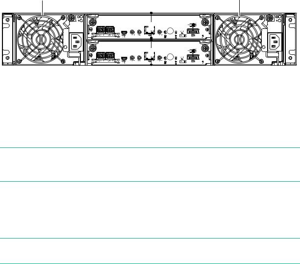
Controller enclosure—rear panel layout
The diagram and table below display and identify important component items comprising the rear panel layout of the MSA 1050 controller enclosure. An enclosure configured with SFPs is shown.
1 |
MSA 1050 controller enclosure |
1 |
|
(rear panel locator illustration) |
|||
|
|
||
|
2 |
|
|
|
3 |
|
1AC Power supplies
2 Controller module A (see face plate detail figures)
3Controller module B (see face plate detail figures)
Figure 4 MSA 1050 Array: rear panel
A controller enclosure accommodates a power supply FRU in each of the two power supply slots (see two instances of callout 1 above). The controller enclosure accommodates two controller module FRUs of the same type within the I/O module slots (see callouts 2 and 3 above).
 IMPORTANT: MSA 1050 controller enclosures support dual-controller only. If a partner controller fails, the array will fail over and run on a single controller until redundancy is restored. A controller module must be installed in each IOM slot to ensure sufficient airflow through the enclosure during operation.
The diagrams with tables that immediately follow provide descriptions of the different controller modules and power supply modules that can be installed into the rear panel of an MSA 1050 controller enclosure. Showing controller modules and power supply modules separately from the enclosure provides improved clarity in identifying the component items called out in the diagrams and described in the tables. Descriptions are also provided for optional drive enclosures supported by MSA 1050 controller enclosures for expanding storage capacity.
NOTE: MSA 1050 controller enclosures support hot-plug replacement of redundant controller modules, fans, power supplies, disk drives, and I/O modules. Hot-add of drive enclosures is also supported.
12 Components

MSA 1050 controller module—rear panel components
Figure 5 shows an 8 Gb FC or 10GbE iSCSI controller module. The SFPs look identical. Refer to the LEDs that apply to the specific configuration of your host interface ports.
|
1 |
5 |
6 |
7 |
= FC LEDs |
2 3 4 |
|
|
8 |
|
|
|
|
= 10GbE iSCSI LEDs |
|
|
1 |
Host ports: used for host connection or replication |
6 |
Service port 1 (used by service personnel only) |
2 |
CLI port (USB - Type B) |
7 Disabled button (used by engineering only) |
|
3 |
Service port 2 (used by service personnel only) |
|
(Sticker shown covering the opening) |
4 |
Reserved for future use |
8 |
SAS expansion port |
5Network management port
Figure 5 MSA 1050 controller module face plate (FC or 10GbE iSCSI)
Figure 6 shows a 1 Gb iSCSI (RJ-45) controller module.
1 |
5 |
6 |
7 |
= FC LEDs
2 3 4 |
8 |
|
= 1 Gb iSCSI LEDs (all host ports use 1 Gb RJ-45 SFPs in this figure) |
||
1 |
Host ports: used for host connection or replication |
6 |
Service port 1 (used by service personnel only) |
2 |
CLI port (USB - Type B) |
7 Disabled button (used by engineering only) |
|
3 |
Service port 2 (used by service personnel only) |
|
(Sticker shown covering the opening) |
4 |
Reserved for future use |
8 |
SAS expansion port |
5Network management port
Figure 6 MSA 1050 controller module face plate (1 Gb RJ-45)
NOTE: For more information about host port configuration, see the topic about configuring host ports within the SMU Reference Guide or online help.
Controller enclosure—rear panel layout |
13 |

1 |
5 |
6 |
7 |
2 3 4 |
8 |
1 |
HD mini-SAS ports: used for host connection |
6 |
Service port 1 (used by service personnel only) |
2 |
CLI port (USB - Type B) |
7 Disabled button (used by engineering only) |
|
3 |
Service port 2 (used by service personnel only) |
|
(Sticker shown covering the opening) |
4 |
Reserved for future use |
8 |
SAS expansion port |
5Network management port
Figure 7 MSA 1050 SAS controller module face plate (HD mini-SAS)
 IMPORTANT: See Connecting to the controller CLI port for information about enabling the controller enclosure USB Type–B CLI port for accessing the CLI to perform initial configuration tasks.
Drive enclosures
Drive enclosure expansion modules attach to MSA 1050 controller modules via the mini-SAS expansion port, allowing addition of disk drives to the system. MSA 1050 controller enclosures support adding the 6 Gb drive enclosures described below.
LFF and SFF drive enclosure — rear panel layout
MSA 1050 controllers support the MSA 2050 LFF Disk Enclosure and the MSA 2050 SFF Disk Enclosure, which share the same rear panel layout, as shown below.
1 |
4 5 |
6 7 |
1 |
|
2 |
|
|
|
3 |
|
|
1 |
Power supplies (AC shown) |
5 |
Service port (used by service personnel only) |
2 |
I/O module A |
6 |
SAS In port |
3 |
I/O module B |
7 |
SAS Out port |
4Disabled button (used by engineering only)
Figure 8 Supported drive enclosures: SFF/LFF rear panel
14 Components

Cache
To enable faster data access from disk storage, the following types of caching are performed:
•Write-back caching. The controller writes user data in the cache memory on the module rather than directly to the drives. Later, when the storage system is either idle or aging—and continuing to receive new I/O data—the controller writes the data to the drive array.
•Read-ahead caching. The controller detects sequential array access, reads ahead into the next sequence of data, and stores the data in the read-ahead cache. Then, if the next read access is for cached data, the controller immediately loads the data into the system memory, avoiding the latency of a disk access.
NOTE: See the SMU Reference Guide for more information about volume cache options.
Transportable CompactFlash
During a power loss or array controller failure, data stored in cache is saved off to non-volatile memory (CompactFlash). The data is then written to disk after the issue is corrected. To protect against writing incomplete data to disk, the image stored on the CompactFlash is verified before committing to disk.
The CompactFlash memory card is located at the midplane-facing end of the controller module as shown below.
Controller module pictorial (Midplane-facing rear view)
CompactFlash memory card
Figure 9 MSA 1050 CompactFlash memory card
If one controller fails, then later another controller fails or does not start, and the Cache Status LED is on or blinking, the CompactFlash will need to be transported to a replacement controller to recover data not flushed to disk (see “Controller failure” (page 45) for more information).
Cache 15

 CAUTION: The CompactFlash memory card should only be removed for transportable purposes. To preserve the existing data stored in the CompactFlash, you must transport the CompactFlash from the failed controller to the replacement controller using a procedure outlined in the HPE MSA Controller Module Replacement Instructions shipped with the replacement controller module. Failure to use this procedure will result in the loss of data stored in the cache module.
 IMPORTANT: In dual controller configurations featuring one healthy partner controller, there is no need to transport failed controller cache to a replacement controller because the cache is duplicated between the controllers, provided that volume cache is set to standard on all volumes in the pool owned by the failed controller.
Supercapacitor pack
To protect RAID controller cache in case of power failure, MSA 1050 controllers are equipped with supercapacitor technology, in conjunction with CompactFlash memory, built into each controller module to provide extended cache memory backup time. The supercapacitor pack provides energy for backing up unwritten data in the write cache to the CompactFlash in the event of a power failure. Unwritten data in CompactFlash memory is automatically committed to disk media when power is restored. While the cache is being maintained by the supercapacitor, the Cache Status LED flashes at a rate of 1/10 second on and 9/10 second off.
Upgrading to the MSA 1050
For information about upgrading components for use with MSA controllers, see Upgrading to the HPE MSA 1050/2050/2052.
16 Components
3Installing the enclosures
Installation checklist
The following table outlines the steps required to install the enclosures and initially configure the system. To ensure a successful installation, perform the tasks in the order they are presented.
Table 2 |
Installation checklist |
|
|
|
|
Step |
Task |
Where to find procedure |
|
|
|
1. |
Install the controller enclosure and optional |
See the racking instructions poster. |
|
drive enclosures in the rack, and attach the |
|
|
bezel or ear caps. |
|
|
|
|
2. |
Connect the controller enclosure and LFF/SFF |
See “Connecting controller and drive enclosures” (page 17). |
|
drive enclosures. |
|
|
|
|
3. |
Connect power cords. |
See the quick start instructions. |
|
|
|
4. |
Test enclosure connections. |
See “Testing enclosure connections” (page 21). |
|
|
|
5. |
Install required host software. |
See “Host system requirements” (page 23). |
|
|
|
6. |
Connect data hosts. |
See “Connecting the enclosure to data hosts” (page 23). |
|
|
If using the optional Remote Snap feature, also see |
|
|
“Connecting two storage systems to replicate volumes” |
|
|
(page 28). |
|
|
|
7. |
Connect remote management hosts. |
See “Connecting remote management hosts” (page 27). |
|
|
|
8. |
Obtain IP values and set management port IP |
See “Obtaining IP values” (page 33). |
|
properties on the controller enclosure. |
See “Connecting to the controller CLI port” (page 32); with |
|
|
Linux and Windows topics. |
|
|
|
9. |
Perform initial configuration tasks1: |
Topics below correspond to bullets at left: |
|
• Sign in to the web-based Storage |
See “Getting Started” in the HPE MSA 1050/2050 SMU |
|
Management Utility (SMU). |
Reference Guide. |
|
• Initially configure and provision the storage |
See “Configuring the System” and “Provisioning the System” |
|
system using the SMU. |
topics (SMU Reference Guide or online help). |
|
|
|
|
|
|
1The SMU is introduced in “Accessing the SMU” (page 38). See the SMU Reference Guide or online help for additional information.
Connecting controller and drive enclosures
MSA 1050 controller enclosures support up to four enclosures (including the controller enclosure). You can cable drive enclosures of the same type or of mixed LFF/SFF model type.
The firmware supports both straight-through and fault-tolerant SAS cabling. Fault-tolerant cabling allows any drive enclosure to fail—or be removed—while maintaining access to other enclosures. Straight-through cabling does not provide the same level of fault-tolerance as fault-tolerant cabling, but does provide some performance benefits as well as ensuring that all disks are visible to the array. Fault tolerance and performance requirements determine whether to optimize the configuration for high availability or high performance when cabling. MSA 1050 controller enclosures support 12 Gb/s disk drives downshifted to 6 Gb/s. Each enclosure has an expansion port using 6 Gb/s SAS lanes. When connecting multiple drive enclosures, use fault-tolerant cabling to ensure the highest level of fault tolerance.
For example, the illustration on the left in Figure 11 (page 20) shows controller module 1A connected to expansion module 2A, with a chain of connections cascading down (blue). Controller module 1B is connected to the lower expansion module (4B) of the last drive enclosure, with connections moving in the opposite direction (green).
Installation checklist |
17 |

Connecting the MSA 1050 controller to the LFF or SFF drive enclosure
The MSA 2050 LFF Disk Enclosure and the MSA 2050 SFF Disk Enclosure can be attached to an MSA 1050 controller enclosure using supported mini-SAS to mini-SAS cables of 0.5 m (1.64') to 2 m (6.56') length [see Figure 10 (page 20)]. Each drive enclosure provides two 0.5 m (1.64') mini-SAS to mini-SAS cables. Longer cables may be desired or required, and can be purchased separately.
Cable requirements for MSA 1050 enclosures
 IMPORTANT:
•When installing SAS cables to expansion modules, use only supported mini-SAS x4 cables with SFF-8088 connectors supporting your 6 Gb application.
•See the QuickSpecs for information about which cables are provided with your MSA 1050 products.
www.hpe.com/support/MSA1050QuickSpecs
(If a website location has changed, an Internet search for “HPE MSA 1050 quickspecs” will provide a link.)
•The maximum expansion cable length allowed in any configuration is 2 m (6.56').
•When adding more than two drive enclosures, you may need to purchase additional 1 m or 2 m cables, depending upon number of enclosures and cabling method used (see QuickSpecs for supported cables):
Spanning 3 or 4 drive enclosures requires 1 m (3.28') cables.
•See the QuickSpecs (link provided above) regarding information about cables supported for host connection:
Qualified Fibre Channel cable options
Qualified 10GbE iSCSI cable options or qualified 10GbE Direct Attach Copper (DAC) cables
Qualified 1 Gb RJ-45 cable options
Qualified HD mini-SAS standard cable and fan-out cable options supporting SFF-8644 and SFF-8088 host connection [also see “12 Gb SAS protocol” (page 25)]:
–SFF-8644 to SFF-8644 cable option is used for connecting to a 12 Gb/s enabled host.
–SFF-8644 to SFF-8088 cable option is used for connecting to a 6 Gb/s enabled host/switch.
–A bifurcated SFF-8644 to SFF-8644 fan-out cable option is used for connecting to a 12Gb/s enabled host.
–A bifurcated SFF-8644 to SFF-8088 fan-out cable option is used for connecting to a 6Gb/s enabled host/switch.
NOTE: Using fan-out cables instead of standard cables will double the number of hosts that can be attached to a single system. Use of fan-out cables will halve the maximum bandwidth available to each host, but overall bandwidth available to all hosts is unchanged.
See SAS fan-out cable option for more information about bifurcated SAS cables.
For additional information concerning cabling of MSA 1050 controllers, visit:
www.hpe.com/support/MSA1050QuickSpecs
www.hpe.com/support/MSA1050BestPractices
Browse for the following reference documents:
•HPE MSA 1050 Cable Configuration Guide
•HPE MSA Remote Snap technical white paper: MSA Remote Snap Software
18 Installing the enclosures
NOTE: For clarity, the schematic illustrations of controller and expansion modules shown in this section provide only relevant details such as expansion ports within the module face plate outline. For detailed illustrations showing all components, see “Controller enclosure—rear panel layout” (page 12).
 IMPORTANT: MSA 1050 controller enclosures support dual-controller only. If a partner controller fails, the array will fail over and run on a single controller until the redundancy is restored. A controller module must be installed in each IOM slot to ensure sufficient airflow through the enclosure during operation.
Connecting controller and drive enclosures |
19 |

|
Controller A |
|
1A |
|
|
|
|
|
Controller B |
|
1B |
1 |
In |
Out |
2A |
|
In |
Out |
2B |
|
|
||
1 = LFF 12-drive or SFF 24-drive enclosure |
|
||
Figure 10 Cabling connections between the MSA 1050 controller and a single drive enclosure
|
Controller A |
1A |
|
|
Controller B |
1B |
|
1 |
In |
Out |
2A |
|
|
|
|
|
In |
Out |
2B |
1 |
In |
Out |
3A |
|
|
||
|
In |
Out |
3B |
|
|
|
|
1 |
In |
Out |
4A |
|
|
|
|
|
In |
Out |
4B |
|
|
|
|
1A |
Controller A |
1B |
Controller B |
2A |
1 |
In |
Out |
|
|
|
|
2B |
|
In |
Out |
|
1 |
In |
Out |
3A |
|
|
|
3B |
|
In |
Out |
|
|
|
|
|
1 |
In |
Out |
4A |
|
|
|
|
|
|
|
4B |
|
In |
Out |
|
|
|
Fault-tolerant cabling |
Straight-through cabling |
1 = LFF 12-drive or SFF 24-drive enclosure
Figure 11 Cabling connections between MSA 1050 controllers and LFF and SFF drive enclosures
The diagram at left (above) shows fault-tolerant cabling of a dual-controller enclosure cabled to either the
MSA 2050 LFF Disk Enclosure or the MSA 2050 SFF Disk Enclosure featuring dual-expansion modules. Controller module 1A is connected to expansion module 2A, with a chain of connections cascading down (blue). Controller module 1B is connected to the lower expansion module (4B), of the last drive enclosure, with connections moving in the opposite direction (green). Fault-tolerant cabling allows any drive enclosure to fail—or be removed—while maintaining access to other enclosures.
20 Installing the enclosures
The diagram at right (above) shows the same storage components connected using straight-through cabling. Using this method, if a drive enclosures fails, the enclosures that follow the failed enclosure in the chain are no longer accessible until the failed enclosure is repaired or replaced.
Figure 11 (page 20) provides example diagrams reflecting fault-tolerant (left) and straight-through (right) cabling for the maximum number of supported MSA 1050 enclosures (four enclosures including the controller enclosure).
 IMPORTANT: For comprehensive configuration options and associated illustrations, refer to the HPE MSA 1050 Cable Configuration Guide.
Testing enclosure connections
NOTE: Once the power-on sequence for enclosures succeeds, the storage system is ready to be connected to hosts, as described in “Connecting the enclosure to data hosts” (page 23).
Powering on/powering off
Before powering on the enclosure for the first time:
•Install all disk drives in the enclosure so the controller can identify and configure them at power-up.
•Connect the cables and power cords to the enclosures as explained in the quick start instructions.
NOTE: Power supplies used in MSA 1050 enclosures
The MSA 1050 controller enclosures and drive enclosures are equipped with AC power supplies that do not have power switches (they are switchless). They power on when connected to a power source, and they power off when disconnected.
•When powering up, make sure to power up the enclosures and associated host in the following order:
Drive enclosures first
This ensures that disks in each drive enclosure have enough time to completely spin up before being scanned by the controller modules within the controller enclosure.
While enclosures power up, their LEDs blink. After the LEDs stop blinking—if no LEDs on the front and back of the enclosure are amber—the power-on sequence is complete, and no faults have been detected. See “LED descriptions” (page 58) for descriptions of LED behavior.
Controller enclosure next
Depending upon the number and type of disks in the system, it may take several minutes for the system to become ready.
Hosts last (if powered down for maintenance purposes)
TIP: When powering off, you will reverse the order of steps used for powering on.
 IMPORTANT: See “Power cord requirements” (page 72) and the QuickSpecs for more information about power cords supported by MSA 1050 enclosures.
Testing enclosure connections |
21 |

AC power supply
Enclosures equipped with switchless power supplies rely on the power cord for power cycling. Connecting the cord from the power supply power cord connector to the appropriate power source facilitates power on, whereas disconnecting the cord from the power source facilitates power off.
Power cord connect |
Figure 12 AC power supply
AC power cycle
To power on the system:
1.Obtain a suitable AC power cord for each AC power supply that will connect to a power source.
2.Plug the power cord into the power cord connector on the back of the drive enclosure (see Figure 12). Plug the other end of the power cord into the rack power source. Wait several seconds to allow the disks to spin up.
Repeat this sequence for each power supply within each drive enclosure.
3.Plug the power cord into the power cord connector on the back of the controller enclosure (see Figure 12). Plug the other end of the power cord into the rack power source.
Repeat the sequence for the controller enclosure’s other switchless power supply.
To power off the system:
1.Stop all I/O from hosts to the system [see “Stopping I/O” (page 41)].
2.Shut down both controllers using either method described below:
Use the SMU to shut down both controllers, as described in the online help and web-posted HPE MSA 1050/2050 SMU Reference Guide.
Proceed to step 3.
Use the CLI to shut down both controllers, as described in the HPE MSA 1050/2050 CLI Reference Guide.
3.Disconnect the power cord female plug from the power cord connector on the power supply module. Perform this step for each power supply module (controller enclosure first, followed by drive enclosures).
22 Installing the enclosures

4Connecting hosts
Host system requirements
Data hosts connected to HPE MSA 1050 arrays must meet requirements described herein. Depending on your system configuration, data host operating systems may require that multi-pathing is supported.
If fault-tolerance is required, then multi-pathing software may be required. Host-based multi-path software should be used in any configuration where two logical paths between the host and any storage volume may exist at the same time. This would include most configurations where there are multiple connections to the host or multiple connections between a switch and the storage.
•Use native Microsoft MPIO DSM support with Windows Server 2016 and Windows Server 2012. Use either the Server Manager or the command-line interface (mpclaim CLI tool) to perform the installation. Refer to the following web sites for information about using Windows native MPIO DSM:
http://support.microsoft.com
http://technet.microsoft.com (search the site for “multipath I/O overview”)
•Use the HPE Multi-path Device Mapper for Linux Software with Linux servers. To download the appropriate device mapper multi-path enablement kit for your specific enterprise Linux operating system, go to www.hpe.com/storage/spock.
Connecting the enclosure to data hosts
A host identifies an external port to which the storage system is attached. The external port may be a port in an I/O adapter (such as an FC HBA) in a server. Cable connections vary depending on configuration. Common cable configurations are shown in this section. A list of supported configurations is available on the Hewlett Packard Enterprise site at: www.hpe.com/support/msa1050:
•HPE MSA 1050 Quick Start Instructions
•HPE MSA 1050 Cable Configuration Guide
These documents provide installation details and describe supported direct attach, switch-connect, and storage expansion configuration options for MSA 1050 products. For specific information about qualified host cabling options, see “Cable requirements for MSA 1050 enclosures” (page 18).
MSA 1050 Storage host interface protocols
The small form-factor pluggable (SFP transceiver of SFP) connectors used in pre-configured host ports of FC and iSCSI MSA 1050 models are further described in the subsections below. Also see “MSA 1050 Storage models” (page 8) for more information concerning use of these host ports.
NOTE: MSA 1050 FC and iSCSI controllers support the optionally-licensed Remote Snap replication feature. Remote Snap supports FC and iSCSI host interface protocols for replication. Use the SMU or CLI commands to create and view replication sets.
MSA 1050 SAS models use high-density mini-SAS (Serial Attached SCSI) interface protocol for host connection. These models do not support Remote Snap replication.
Fibre Channel protocol 
The MSA 1050 controller enclosures support two controller modules using the Fibre Channel interface protocol for host connection. Each controller module provides two host ports designed for use with an FC SFP supporting data rates up to 8 Gb/s. MSA 1050 FC controllers can also be cabled to support the optionally-licensed Remote Snap replication feature via the FC ports.
Host system requirements |
23 |

The MSA 1050 FC controllers support Fibre Channel Arbitrated Loop (public or private) or point-to-point topologies. Loop protocol can be used in a physical loop or in a direct connection between two devices. Point-to-point protocol is used to connect to a fabric switch. Point-to-point protocol can also be used for direct connection. See the set host-parameters command within the CLI Reference Guide for command syntax and details about connection mode parameter settings relative to supported link speeds.
Fibre Channel ports are used in either of two capacities:
•To connect two storage systems through a Fibre Channel switch for use of Remote Snap replication.
•For attachment to FC hosts directly, or through a switch used for the FC traffic.
The first usage option requires valid licensing for the Remote Snap replication feature, whereas the second option requires that the host computer supports FC and optionally, multipath I/O.

 TIP: Use the SMU Configuration Wizard to set FC port speed. Within the SMU Reference Guide, see “Using the Configuration Wizard” and scroll to FC port options. Use the set host-parameters CLI command to set FC port options, and use the show ports CLI command to view information about host ports.
10GbE iSCSI protocol 
The MSA 1050 controller enclosures support two controller modules using the Internet SCSI interface protocol for host connection. Each controller module provides two host ports designed for use with a 10GbE iSCSI SFP or approved DAC cable supporting data rates up to 10 Gb/s, using either one-way or mutual CHAP (Challenge-Handshake Authentication Protocol).

 TIP: See the topics about configuring CHAP, and CHAP and replication in the SMU Reference Guide.

 TIP: Use the SMU Configuration Wizard to set iSCSI port options. Within the SMU Reference Guide, see “Using the Configuration Wizard” and scroll to iSCSI port options. Use the set host-parameters CLI command to set iSCSI port options, and use the show ports CLI command to view information about host ports.
The 10GbE iSCSI ports are used in either of two capacities:
•To connect two storage systems through a switch for use of Remote Snap replication.
•For attachment to 10GbE iSCSI hosts directly, or through a switch used for the 10GbE iSCSI traffic.
The first usage option requires valid licensing for the Remote Snap replication feature, whereas the second option requires that the host computer supports Ethernet, iSCSI, and optionally, multipath I/O.
1 Gb iSCSI protocol 
The MSA 1050 controller enclosures support two controller modules using the Internet SCSI interface protocol for host port connection. Each controller module provides two iSCSI host ports configured with an RJ-45 SFP supporting data rates up to 1 Gb/s, using either one-way or mutual CHAP.

 TIP: See the topics about configuring CHAP, and CHAP and replication in the SMU Reference Guide.

 TIP: Use the SMU Configuration Wizard to set iSCSI port options. Within the SMU Reference Guide, see “Using the Configuration Wizard” and scroll to iSCSI port options. Use the set host-parameters CLI command to set iSCSI port options, and use the show ports CLI command to view information about host ports.
24 Connecting hosts
Loading...