


HP NetServer LH 6000/LH 6000r
Service Manual
Online Version: 1.1
Last Updated: May 2000

Notice
The information contained in this document is subject to change without notice.
Hewlett-Packard makes no warranty of any kind with regard to this material, including, but not limited to, the implied warranties of merchantability and fitness for a particular purpose. Hewlett-Packard shall not be liable for errors contained herein or for incidental or consequential damages in connection with the furnishing, performance, or use of this material.
Hewlett-Packard assumes no responsibility for the use or reliability of its software on equipment that is not furnished by Hewlett-Packard.
This document contains proprietary information that is protected by copyright. All rights are reserved. No part of this document may be photocopied, reproduced, or translated to another language without the prior written consent of Hewlett-Packard Company.
Intel® and Pentium® are registered trademarks of Intel Corporation. Pentium® II Xeon and Pentium® III Xeon are trademarks of Intel Corporation.
Windows NT® and Windows 95® are registered trademarks of Microsoft in the U.S. and other countries. Torx® is a registered trademark of CamCar/Textron, Inc.
Hewlett-Packard Company Network Server Division
Technical Communications/MS 45SLE 10955 Tantau Avenue
Cupertino, CA 95014 USA
© Copyright 2000, Hewlett-Packard Company.
Audience Assumptions
This guide is for the person who services LAN servers. Hewlett-Packard Company assumes you are qualified in the servicing of computer equipment and trained in recognizing hazards in products with hazardous energy levels and are familiar with weight and stability precautions for rack installations.
ii

Contents
1..General Information ..................................................................................................................................... |
1 |
Notice to Service Technicians........................................................................................................................ |
1 |
Removing Covers - Pedestal LH6000............................................................................................................ |
1 |
Removing Covers - Rack Mount LH6000r ..................................................................................................... |
3 |
Removing the System Board Assembly......................................................................................................... |
7 |
Front View ...................................................................................................................................................... |
9 |
Rear View..................................................................................................................................................... |
10 |
Lights and Indicators .................................................................................................................................... |
10 |
Front Panel Console Switch and Indicator Descriptions.......................................................................... |
11 |
Indicators and Controls behind the LH 6000r Front Bezel....................................................................... |
12 |
Hard Disk Drive LED Indicators ............................................................................................................... |
12 |
LEDs at the Rear of the Chassis ............................................................................................................. |
13 |
Main Menu.................................................................................................................................................... |
14 |
Viewing System Information .................................................................................................................... |
15 |
Event Log Menu ........................................................................................................................................... |
15 |
2..System Information.................................................................................................................................... |
17 |
Boot Priority.................................................................................................................................................. |
17 |
IRQ Settings................................................................................................................................................. |
17 |
Connector Pinouts........................................................................................................................................ |
17 |
Video Connector Pinouts ......................................................................................................................... |
17 |
Serial Port Connector............................................................................................................................... |
18 |
Parallel Port Connector............................................................................................................................ |
19 |
50-Pin Narrow SCSI Port Connector ....................................................................................................... |
19 |
Mini-DIN Connectors................................................................................................................................ |
20 |
Memory Guidelines ...................................................................................................................................... |
21 |
Mass Storage Guidelines ............................................................................................................................. |
22 |
Accessory Board Guidelines ........................................................................................................................ |
23 |
Hot Addition and Replacement of Hot Plug PCI Boards.......................................................................... |
23 |
Online Replacement, Hot Swapping, of a PCI Adapter ........................................................................... |
24 |
Remote Control (Top Tools) Board.............................................................................................................. |
24 |
HP NetRAID Guidelines ............................................................................................................................... |
24 |
iii

Contents
To disable SCSI A channel: ..................................................................................................................... |
24 |
To configure the drive(s) in the hot-swap cage as a RAID array:............................................................ |
25 |
Processors Guidelines ................................................................................................................................. |
25 |
Technical Specification................................................................................................................................. |
26 |
Video ........................................................................................................................................................ |
26 |
Environment Specifications...................................................................................................................... |
27 |
Dimensions .............................................................................................................................................. |
27 |
Power Requirements................................................................................................................................ |
28 |
Switch Settings............................................................................................................................................. |
28 |
System Board Assembly Illustration............................................................................................................. |
30 |
System Board Illustration ............................................................................................................................. |
30 |
I/O Board Illustration..................................................................................................................................... |
31 |
Power Management/Interconnect Board Illustration .................................................................................... |
32 |
3 . Parts Information........................................................................................................................................ |
33 |
Exploded View - Covers, Bezel, Front Panel ............................................................................................... |
33 |
Exploded View - Power Supply, I/O Board, Fans......................................................................................... |
34 |
Exploded View - Mass Storage .................................................................................................................... |
35 |
Exploded View - System Board Assembly................................................................................................... |
36 |
Exploded View - Exhaust Fans .................................................................................................................... |
37 |
Replaceable Parts List ................................................................................................................................. |
38 |
Keyboards ................................................................................................................................................ |
41 |
Power Cords ............................................................................................................................................ |
41 |
Cabling Diagram ...................................................................................................................................... |
41 |
4 . Diagnostics ................................................................................................................................................. |
43 |
Diagnostic Tests........................................................................................................................................... |
43 |
Diagnostics Description................................................................................................................................ |
43 |
HP NetServer DiagTools .............................................................................................................................. |
44 |
DiagTools Capabilities ............................................................................................................................. |
44 |
Event Log Menu ........................................................................................................................................... |
45 |
POST Routines............................................................................................................................................. |
46 |
Beep Codes.................................................................................................................................................. |
47 |
Error Messages ............................................................................................................................................ |
48 |
5 . Troubleshooting ......................................................................................................................................... |
55 |
iv

|
Contents |
Preventive Maintenance Procedures ........................................................................................................... |
55 |
Troubleshooting Tips.................................................................................................................................... |
55 |
General Troubleshooting Sequence ........................................................................................................ |
56 |
The System Will Not Power Up ............................................................................................................... |
57 |
The System Will Not Boot ........................................................................................................................ |
57 |
Intermittent Failures ................................................................................................................................. |
57 |
Clearing the System Configuration .............................................................................................................. |
57 |
Password Problems ..................................................................................................................................... |
59 |
BIOS Recovery............................................................................................................................................. |
60 |
Troubleshooting Checklist............................................................................................................................ |
61 |
General System Problems ........................................................................................................................... |
62 |
Memory Problems ........................................................................................................................................ |
64 |
CD-ROM Problems ...................................................................................................................................... |
65 |
Flexible Disk Drive Problems ....................................................................................................................... |
66 |
Keyboard and Mouse Problems................................................................................................................... |
67 |
Network Interface Card Problems................................................................................................................ |
67 |
Power Problems........................................................................................................................................... |
68 |
SCSI Subsystem Problems.......................................................................................................................... |
69 |
Video/Monitor Problems............................................................................................................................... |
73 |
Configuration Problems................................................................................................................................ |
75 |
Verifying Hard Disk Drive Operation ............................................................................................................ |
76 |
Processor Problems..................................................................................................................................... |
77 |
Printer/DataComm Problems ....................................................................................................................... |
78 |
6..Replacing Parts .......................................................................................................................................... |
79 |
Safety Information ........................................................................................................................................ |
79 |
Service Tools Required................................................................................................................................ |
79 |
Replacing Power Supply Module(s)............................................................................................................. |
79 |
Replacing the Control Panel ........................................................................................................................ |
80 |
Replacing the HP NetRAID DIMM ............................................................................................................... |
81 |
Replacing the System Battery...................................................................................................................... |
82 |
Replacing the NetRAID Battery Backup Module (Optional)......................................................................... |
84 |
Replacing System Memory .......................................................................................................................... |
85 |
Replacing a Processor ................................................................................................................................. |
88 |
v

Contents
Replacing a VRM.......................................................................................................................................... |
89 |
Replacing the Power Supply Fans ............................................................................................................... |
90 |
Replacing the Rear Chassis Fans................................................................................................................ |
91 |
Replacing the I/O Fans................................................................................................................................. |
92 |
Replacing the Processor Fans ..................................................................................................................... |
92 |
Replacing the Hot Swap Mass Storage Cage.............................................................................................. |
94 |
Replacing the I/O Board ............................................................................................................................... |
95 |
Replacing the Processor Board.................................................................................................................... |
97 |
Replacing the System Board........................................................................................................................ |
99 |
Replacing the Power Management/Interconnect Board ............................................................................ |
101 |
Replacing the PCI Hot-Swap Assembly..................................................................................................... |
103 |
Index............................................................................................................................................................... |
105 |
vi

1 General Information
Notice to Service Technicians
This is the service document for the HP NetServer LH6000 server. You also need to access the HP NetServer LH6000 Installation Guide which comes with the server and is also available on the Network Server Division WEB site and on the Information Assistant Documentation CD-ROM.
The LH6000 installation guide contains additional information on the installation process that the end users follow. Both documents are needed for complete servicing information.
Removing Covers - Pedestal LH6000
WARNING Before removing covers, disconnect the power cords and unplug telephone cables. If possible, shut down the operating system. Disconnect the power cords to avoid exposure to high energy levels that may cause burns when parts are short-circuited by metal objects, such as tools or jewelry. Disconnect telephone cables to avoid exposure to shock hazard from telephone ringing voltages.
Wear a grounded wrist strap and use a static-dissipating work surface when handling NetServer components. Note that the power switch does not turn off the standby power. Disconnect the power cords to turn off standby power.
NOTE |
If the backlight of the LCD is on, standby power is also on. |
1.Unlock the bezel, using the supplied key.
The bezel connects to the chassis with two snap-in connectors inside its top left and right corners and two tabs that fit into two slots on the bottom of the chassis.
2.Remove the bezel.
a.Pull bezel toward you until it unsnaps.
b.Lift the bezel forward and upward from the chassis face.
1
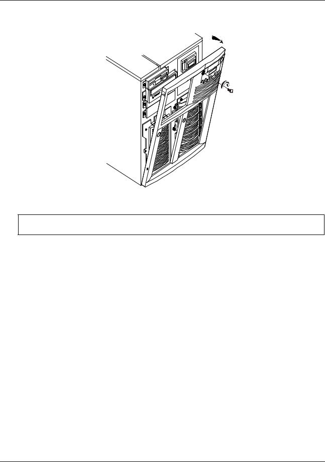
Chapter 1 General Information
(1) |
Unlock the bezel. |
|
(2) |
Pull bezel toward you, then |
|
(3) up and away from the front panel, |
2 |
|
releasing the tabs from the slots |
|
|
at the bottom of the front panel.
3 
1
Removing the HP NetServer LH 6000 Bezel
CAUTION The NetServer covers are heavy. Support them as you remove them, and allow room to move them away from the NetServer and for storage when removed.
3.Once you have removed the bezel, remove the left cover by loosening the thumbscrew and then pulling the cover forward to disengage it. Lift it outward and away from the chassis.
4.Remove the top cover by loosening the thumbscrew, pulling the cover forward and then slightly sideways to disengage it. Lift it up and away from the chassis.
5.Remove the right cover by loosening the thumbscrew and pulling the cover forward to disengage it. Lift it outward and away from the chassis.
2

Chapter 1 |
General Information |
Top Cover
Thumbscrew
Thumbscrew
Left Cover |
Right Cover |
|
Thumbscrew
HP NetServer LH 6000 Covers
Removing Covers - Rack Mount LH6000r
WARNING Before removing covers, disconnect the power cords and unplug telephone cables. If possible, shut down the operating system. Disconnect the power cords to avoid exposure to high energy levels that may cause burns when parts are short-circuited by metal objects, such as tools or jewelry. Disconnect telephone cables to avoid exposure to shock hazard from telephone ringing voltages.
Wear a grounded wrist strap and use a static-dissipating work surface when handling NetServer components. Note that the power switch does not turn off the standby power. Disconnect the power cords to turn off standby power.
NOTE |
If the backlight of the LCD is on, standby power is also on. |
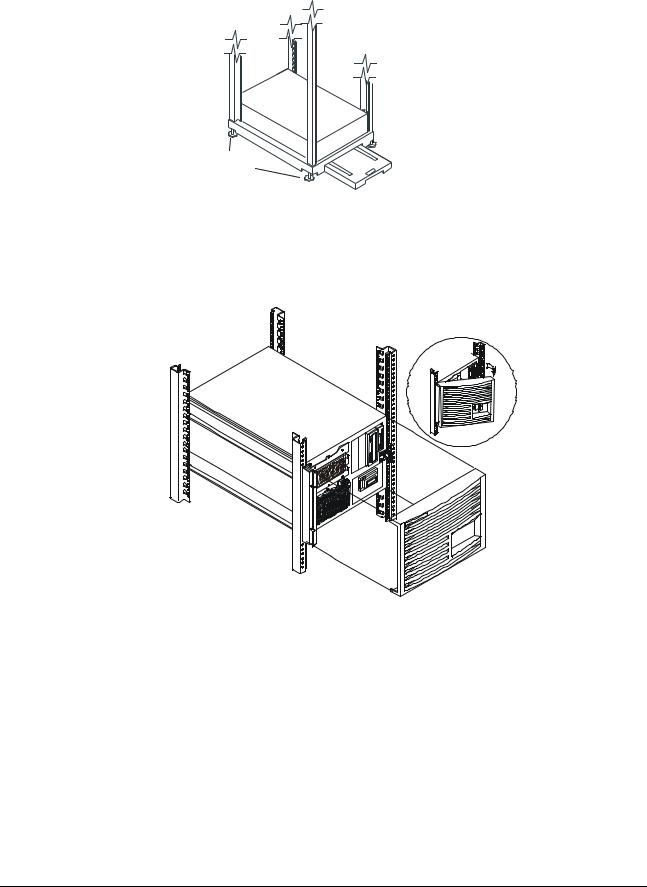
1. Extend the anti-tip foot from under the front of the rack.
WARNING This anti-tip device must be extended to prevent the rack and NetServer from tipping over, which could damage the NetServer and injure people.
3
Chapter 1 |
General Information |
Leveler
Anti-Tip
Foot
Feet
Rack Anti-tip Foot
2.Remove the bezel from the front of the HP NetServer by swinging the bezel open (past 90 degrees) until it releases from the three posts on the bezel hinge.
Removing the HP NetServer LH 6000r Bezel
3.Use a Torx 15 screwdriver to unscrew the four screws securing the HP NetServer to the rack.
4.Do not unscrew the entire hinge or bracket from the HP NetServer. Remove only the outer screws so the hinge and the bracket remain attached to the HP NetServer chassis.
4
Chapter 1 |
General Information |
Remove two screws securing the NetServer to the rack.
Do not remove three screws securing the hinge to the NetServer .
Top Cover |
Remove two |
|
screws securing |
|
the NetServer |
|
to the rack. |
Do not remove two screws securing the bracket
to the NetServer .
Right Cover
Bottom Cover
Front of LH 6000r Screw and Cover Locations
4 


 Z-Bracket
3
2 |
|
1 |
Remove the |
|
two screws |
|
holding the |
NetServer to the bracket
Remove Z-bracket
5.The Z-bracket is used only during shipment to secure the HP NetServer to the rack. To remove the Z-bracket, remove the two screws that connect the Z-bracket to the column at the rear of the HP NetServer. Save the Z-bracket for future use.
6.At the front of the HP NetServer, pull the NetServer forward from the rack until you hear the lockout device engage with a click.
5

Chapter 1 |
General Information |
Locking
Latch
Locking Latch
CAUTION The HP NetServer covers are heavy. Support them as you remove them, and allow room to move them away from the HP NetServer and for storage.
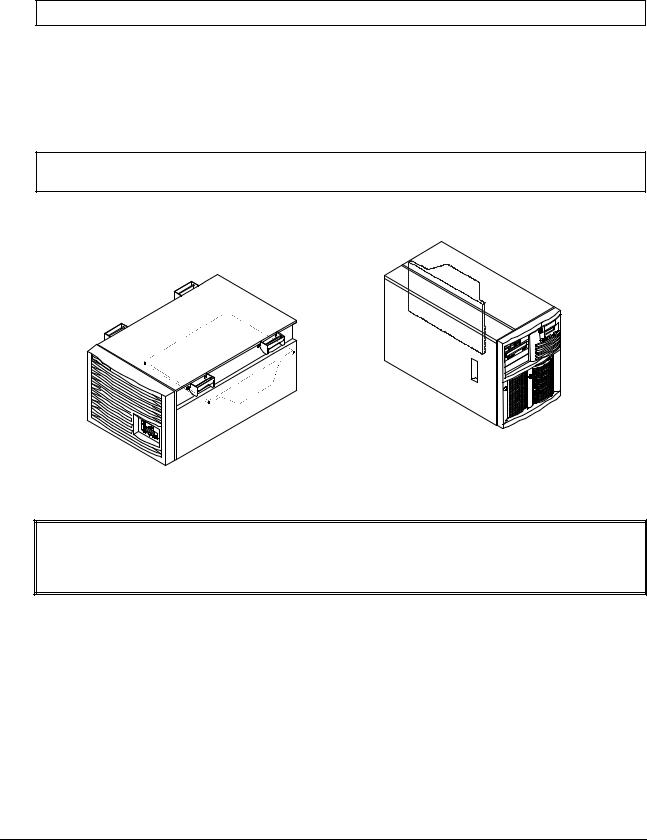
7.Remove the Top Cover by loosening the thumbscrew and sliding the cover forward to disengage it. Lift it up and away from the chassis.
Top Cover
Thumbscrew
Right Cover
Thumbscrew
 Thumbscrew
Bottom Cover
HP NetServer LH 6000r Covers
8.Remove the Right Cover by supporting it with your hand, then loosening the thumbscrew and pulling the cover forward to disengage it. Lift it away from the chassis.
9.Remove the Bottom Cover by supporting it with your hand, and loosening the thumbscrew with the other hand. Pull the cover forward to disengage it and catch it as it falls away from the chassis.
6
Chapter 1 |
General Information |
Removing the System Board Assembly
CAUTION Extend the anti-tip foot prior to any work on a rack-mount server.
1.Log off all users and gracefully shut down the network operating system according to directions in your NOS documentation.
2.Power down the HP NetServer.
3.Disconnect the power cords and cables, and if necessary, label each one to support reassembly.
CAUTION The power supplies will continue to provide standby current to the NetServer until the power is disconnected.
4. Follow the instructions in removing the covers to gain access to the system board assembly.
Location of System Board Assembly
WARNING Always disconnect the power cords before removing the covers, to avoid exposure to high energy levels that may cause burns when parts are short-circuited by metal objects such as tools or jewelry. Disconnect any telephone cables to avoid exposure to shock hazard from telephone ringing voltages.
5. Unlatch the blue retaining latches to release the board.
7
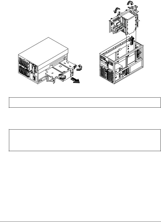
Chapter 1 |
General Information |
Removing the System Board Assembly
CAUTION The system board assembly weighs approximately 20 lbs. (9 kgs.). Removing the board assembly with the assistance of another person is advised.
6.Pull the board out until it clears the chassis guides.
7.Slide the system board assembly from the chassis and place it metal plate side down on an anti-static pad.
CAUTION Do not operate the HP NetServer for more than sixty minutes without first installing all covers and the front bezel. Operating the system without all covers in place reduces critical cooling airflow over some components, such as hard disk drives and processors. Operating the system without all covers in place may result in failure of these components.
8

Chapter 1 |
General Information |
Front View
Front of LH6000r Chassis
Front Panel
Console
LH 6000r Bezel and Front Panel Console
Front of LH6000 Chassis
|
Protective |
Reset |
Door |
|
(shown open) |
|
Front Panel |
|
Console |
LH 6000 Bezel and Front Panel Console
9

Chapter 1 |
General Information |
Rear View
The HP NetServer's rear panel includes communication ports, the AC power connectors, and the HP NetServer's two power supplies cages. The four hot plug PCI slots LEDs are above power supply 4.
Serial Port |
|
Parallel Port |
1 |
|
|
Mouse Port |
2 |
3 |
|
Keyboard Port |
4 |
5 |
|
LAN Port |
6 |
7 |
|
|
8 |
Monitor Port
1 |
2 |
3 |
4 |
Power
Supplies
Power Supply
Status LEDs
Power
Connectors
Remote
Management
Port
Hot Plug
PCI LEDs
Rear Panel of the HP NetServer
The optional Redundancy Kit provides a fourth power supply. Since the HP NetServer requires three power supplies to run, a fourth power supply helps to prevent service interruptions. With the Redundancy Kit installed, a power supply can be hot-swapped.
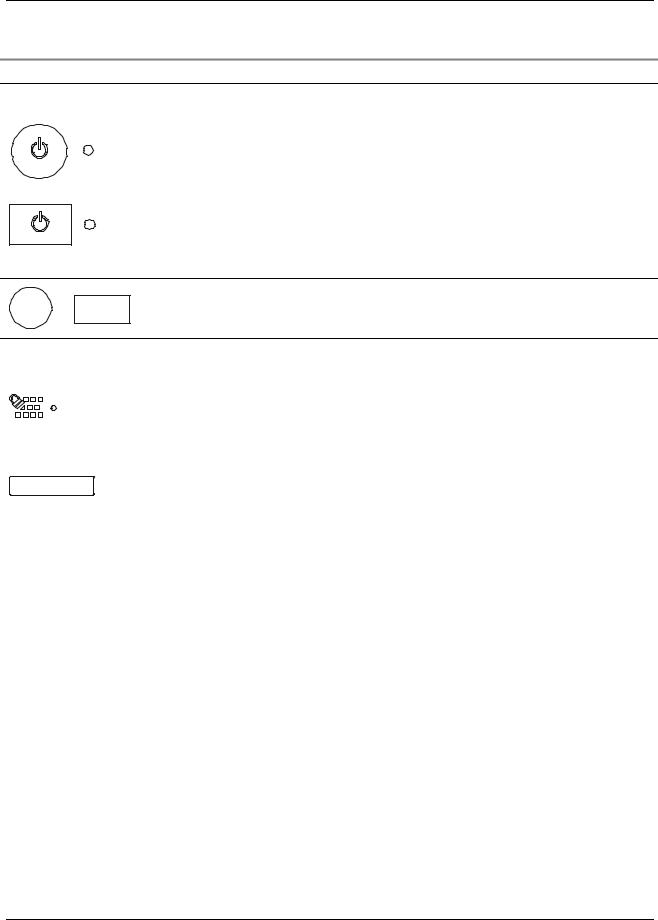
Lights and Indicators
This is the HP NetServer LH 6000's Front Panel Console (LH 6000r is similar, but has no lock).
Small door reveals this panel
Lock |
Power |
Power-on |
Reset |
Secure |
Secure |
|
Switch |
LED |
Switch |
Mode |
Mode |
|
|
|
|
Switch |
LED |
RESET
Status
Screen
Server
Status
LEDs
Escape Enter |
Scroll |
Scroll |
|
Down |
Up |
10
Chapter 1 General Information
Front Panel Console Switch and Indicator Descriptions
Control |
Description |
DC Power Switch |
Turns the HP NetServer on and off. This switch is under the door on the front panel. |
and LED |
Push once to turn on, again to turn off. As long as the AC power is connected to the |
|
HP NetServer, standby power is present. |
|
l If the LED is steady green, then the HP NetServer is powered-up. |
|
l If the LED is flashing green, the HP NetServer is in a power-save mode. |
|
l If the LED is off, but the two-line display has a message, standby power is |
|
present. |
|
l To go into power-save mode, depress the power switch; you must press it for |
|
over ten seconds to effect a power down. |
|
Resets the HP NetServer. This switch may be disabled by Secure mode. |
RESET Or RESET |
|
Secure Mode
Switch and
Indicator
Locks system keyboard, monitor display, and control panel to prevent unauthorized use. Go to the Setup utility security menu to configure this feature. Secure Mode indicator illuminates when Secure Mode is enabled.
Status screen |
Reports system status. |
||
|
|
|
|
Red |
Yellow |
Green |
|
LED |
LED |
LED |
Indicates HP NetServer Status: |
Off |
Off |
Off |
Main power is off and the HP NetServer may or may not be on standby |
|
|
|
power. |
Flashing |
Off |
Off |
Immediate attention required due to a failed component in the HP |
|
|
|
NetServer. The HP NetServer may not be fully operational, due to this |
|
|
|
condition, such as POST errors. |
Off |
Flashing |
Off |
Attention required due to a pre-failure condition. This condition may be |
|
|
|
caused by a component failure (for example, a redundant fan or power |
|
|
|
supply) that could lead to a critical component failure, such as a processor |
|
|
|
module exceeding its operating temperature. If the failed component is |
|
|
|
redundant, the HP NetServer may still be operating normally. |
Off |
Off |
On |
The HP NetServer is operating normally. |
11
Chapter 1 General Information
Indicators and Controls behind the LH 6000r Front Bezel
Headphone Jack |
Eject |
Activity LED |
|
CD ROM Drive |
Button |
|
|
Access Button |
Flexible Disk Drive |
Volume Control |
|
|
Activity LED |
Internal Drive |
|
Bays |
|
(Non-hot-swap) |
|
CD-ROM, Flexible Disk Drive, and HDD LEDs
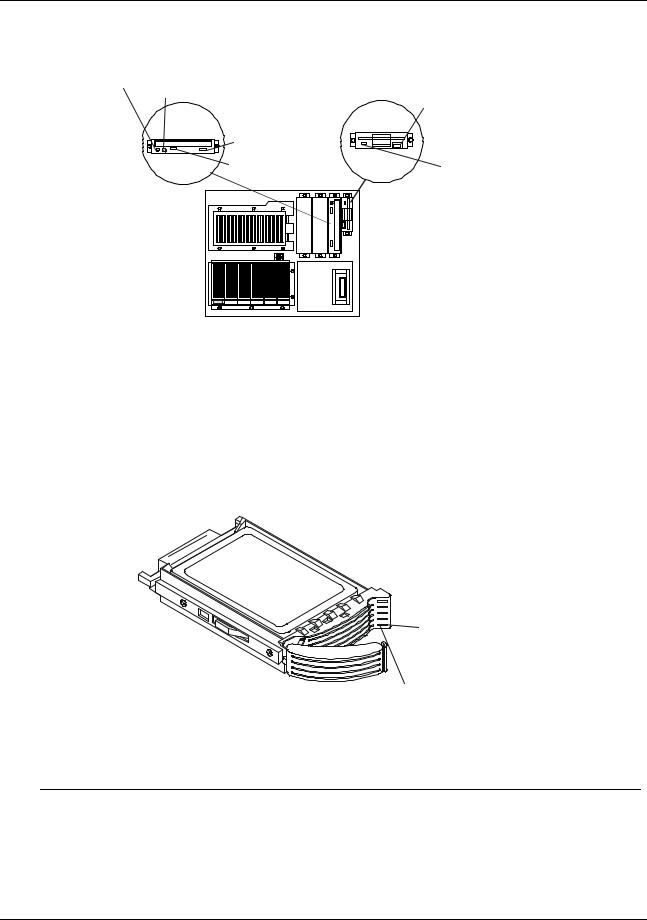
Hard Disk Drive LED Indicators
Each hot-swap hard disk drive module has to LED apertures on its front, one for power status and one for activity status. Light pipes on the module transmit light to these apertures from LEDs on the inside rear of the hot-swap mass storage cage.
Activity status
LED aperture
Power status
LED aperture
LED Apertures on Hot-Swap Hard Disk Drive Module
NOTE |
The Activity LED for a drive flashes green when the drive is accessed. |
12
Chapter 1 General Information
Status LED |
Condition |
|
|
Red Fast Flashing |
Drive Fault |
Amber Normal Flashing |
Drive Failure Predicted |
Green Solid |
Drive Present and Normal |
|
|
Red Solid |
12V Fault |
LEDs at the Rear of the Chassis
PCI Attention LEDs
If a hot plug board needs attention, its LED glows amber.
1 |
2 |
3 |
4 |
5 |
6 |
7 |
8 |
Slot 5 needs attention
Amber Attention LED
When an amber PCI LED appears, you must remove the cover to see the internal PCI Power LEDs for each hot plug PCI slot.
PCI Power LEDs (Internal)
Four pairs of very small LEDs are on the I/O board above left of each hot plug PCI slot.
Power (Green) 
 Attention (Amber)
 5
5 


Onboard LEDs
The light from the small onboard LEDs is visible through the light pipes on the plastic slot separators.
Onboard LEDs
Green (Power) LED
Amber (Attention) LED
13

|
Chapter 1 |
|
|
General Information |
|
|
|
|
Light Pipes Display PCI LEDs |
|
|
|
PCI Hot Plug LEDs (Internal) |
|
|
||
|
Amber |
Green |
Status Indicated |
Your Action |
|
|
|
|
|
|
|
|
Off |
On |
Power to the slot is on, and the slot is |
Do not remove the board from the slot. |
|
|
|
|
operating normally. |
|
|
|
On |
On |
The slot needs attention, but power |
Do not remove the board from the slot. |
|
|
|
|
to the slot is on. |
|
|
|
On |
Off |
The slot needs attention, but power |
You can safely remove the board from this |
|
|
|
|
to the slot is off. |
slot. |
|
|
Off |
Off |
Power to the slot is off. |
You can safely remove the board from this |
|
|
|
|
|
slot. |
|
Power Supply LEDs
Interpret the green LEDs on the power supplies in this way:
Green LED |
Indicates this HP NetServer Status: |
|
|
Steady Green |
The system is powered up. |
Flashing |
The system is in stand-by or power-save mode. |
|
|
Off |
The AC line is unplugged or the power supply has failed. |
|
|
LAN LEDs
The LH 6000 has two LEDs on either side of the RJ-45 connection. Interpret the LEDs in this way:
Local Area Network LED Status
Green LED |
Yellow LED |
LAN Status: |
|
|
|
On/Flashing |
Off |
The LAN is connected and data is being transferred at 10Mbps. |
On/Flashing |
On |
The LAN is connected and data is being transferred at 100Mbps. |
Off |
Off |
The LAN is not connected or is not operational. |
Main Menu
This is the status screen default display for the LH 6000:
HP NetServer
LH 6000
1. To reach the main menu from this default screen, press the Enter button.
NOTE The status screen displays two lines of an entire menu at a time.
This is the entire Main Menu:
***Main Menu****
>Event Log >FW Info >System Info
>Component Info >Service
>Adjust Contrast
14
Chapter 1 |
General Information |
Menus beginning with a greater-than symbol (>) indicate sub-menu selections.
2.Use the arrow buttons to move the cursor to your selection and press the Enter button. A cursor highlights the currently selected line.
3.To return to the Main Menu from one of these selections, press Escape.
4.To exit the Main Menu, press Escape.
Viewing System Information
Use the HP NetServer’s status screen and buttons to view system configuration information, a log of current and past conditions, replaceable parts information, adjust screen contrast, and more.
Front Panel Console Buttons
|
Button Name |
|
Description |
|
|
|
|
|
|
|
Escape |
|
Return to a previous menu |
|
|
|
|
|
|
|
Enter |
|
Select an item from a menu. |
|
|
|
|
|
|
|
|
|
|
|
|
Down Arrow |
|
Scroll down one line through the current screen or menu. |
|
|
|
|
|
|
|
|
|
|
|
|
Up Arrow |
|
Scroll up one line through the current screen or menu. |
|
|
|
|
|
|
|
Left Arrow |
|
Adjust contrast (when adjust contrast menu selected) |
|
|
Right Arrow |
|
Adjust contrast (when adjust contrast menu selected) |
|
|
|
|
|
|
|
NOTE |
The buttons and menus operate when the HP NetServer has powered down or |
||
|
|
hung, as long as the NetServer is plugged in. During POST (power-on self-test) the |
||
|
|
buttons and menus are disabled temporarily so that the status screen can display |
||
|
|
POST and boot messages. |
|
|
Event Log Menu
The Event Log menu has information about current and resolved events. The menu provides a list of all events currently in the log. These may be errors, or normal system events like a system boot.
NOTE |
You can view system events in the status screen and in the Event Log Report Utility |
|
in NetServer Utilities on Navigator. The details may differ slightly. |
15

Chapter 1 |
General Information |
16

2 System Information
Boot Priority
Some boards have preferred slot locations. Consider the boot order when choosing the accessory board slot in which to install the accessory board.
This is the default boot priority for the LH 6000/6000r:
1.IDE CD-ROM drive with a bootable CD-ROM
2.Flexible disk drive with a bootable flexible disk
3.HP NetRAID controller or integrated Embedded SCSI controller
4.PCI boards in slots in the following order: 8, 7, 6, 5, 4, 3, 2, and 1 Change this boot order using the Setup utility.
IRQ Settings
The BIOS automatically assigns the IRQs (hardware interrupts) for each PCI slot and embedded device in the HP NetServer during boot. These assignments trigger the NOS to enable the APIC (Advanced Programmable Interrupt Controller). APIC takes advantage of the expanded set of non-conflicting IRQs for those accessory boards requiring more than one IRQ per slot. APIC provides up to four dedicated interrupts for each PCI slot.
These automatic IRQ assignments can be changed in the setup screen (F2).
Connector Pinouts
Unless otherwise noted, the following features apply to all models. Some features are factory installed; others are optional.
Video Connector Pinouts
The built-in video uses the standard 15-pin analog display pinout configuration. The pinouts for your monitor may vary. For the pinouts for your monitor, refer to the manual that came with your monitor.
6 |
|
|
|
|
|
|
1 |
|
|
|
|
11 |
|
7 |
|
|
|
|
||
|
|
|
||||
2 |
|
|
|
|
12 |
|
8 |
|
|
|
|
||
3 |
|
|
|
|
13 |
|
9 |
|
|
|
|
||
4 |
|
|
|
|
14 |
|
10 |
|
|
|
|
||
|
|
|
|
|
15 |
|
5 |
|
|
|
|
||
|
|
|
|
|
||
|
|
|
Video Connector Pinouts
17
Chapter 2 System Information
Video Connector Pinouts
Pin Number |
Function |
Pin Number |
Function |
|
|
|
|
1 |
Red |
9 |
Key (no pin) |
|
|
|
|
2 |
Green |
10 |
Sync return (ground) |
|
|
|
|
3 |
Blue |
11 |
Monitor ID bit 0 |
|
|
|
|
4 |
Monitor ID bit 2 |
12 |
Monitor ID bit 1 |
|
|
|
|
5 |
Monitor self test (ground) |
13 |
Horizontal sync (+) |
|
|
|
|
6 |
Red return (ground) |
14 |
Vertical sync (-) |
|
|
|
|
7 |
Green return (ground) |
15 |
Not used |
|
|
|
|
8 |
Blue return (ground) |
|
|
|
|
|
|
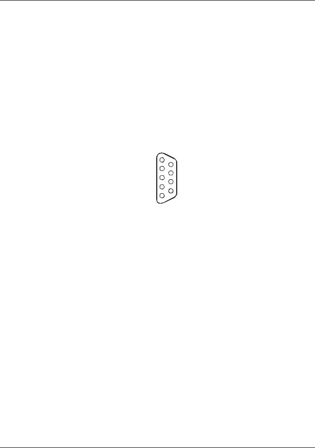
Serial Port Connector
|
5 |
|
|
|
9 |
|
|
|
|
||
|
4 |
|
|
|
|
|
|
|
|
8 |
|
|
3 |
|
|
|
|
|
|
|
|
7 |
|
|
2 |
|
|
|
|
|
|
|
|
6 |
|
|
1 |
|
|
|
|
|
|
|
|
|
|
|
Serial Port Connector Pinouts |
||||
Serial Port Connector Pinouts |
|
|
|||
Pin Number |
|
|
|
Signal Description |
|
|
|
|
|
||
1 |
Data carrier detect |
|
|
||
2 |
Receive data |
|
|
||
3 |
Transmit data |
|
|
||
4 |
Data term ready |
|
|
||
5 |
Signal ground |
|
|
||
6 |
Data set ready |
|
|
||
7 |
Request to send |
|
|
||
|
|
|
|
||
8 |
Clear to send |
|
|
||
9 |
Ring indicator |
|
|
||
18
Chapter 2 System Information
Parallel Port Connector
|
1 |
|
|
|
|
|
14 |
|
|
|
|
|
|
|
|
||
|
2 |
|
|
|
|
|
||
|
|
|
|
|
|
15 |
|
|
|
|
|
|
|
|
|
||
|
3 |
|
|
|
|
|
||
|
|
|
|
|
|
16 |
|
|
|
|
|
|
|||||
|
|
|
|
|
||||
|
4 |
|
|
|
|
|
17 |
|
|
|
|
|
|
|
|
||
|
5 |
|
|
|
|
|
||
|
|
|
|
|
|
18 |
|
|
|
|
|
|
|
|
|
||
|
6 |
|
|
|
|
|
||
|
|
|
|
|
|
19 |
|
|
|
|
|
|
|
|
|
||
|
7 |
|
|
|
|
|
||
|
|
|
|
|
|
20 |
|
|
|
|
|
|
|
|
|
||
|
8 |
|
|
|
|
|
||
|
|
|
|
|
|
21 |
|
|
|
|
|
|
|||||
|
|
|
|
|
||||
|
9 |
|
|
|
|
|
22 |
|
|
|
|
|
|
|
|
||
|
10 |
|
|
|
|
|
||
|
|
|
|
|
|
23 |
|
|
|
|
|
|
|
|
|
||
|
11 |
|
|
|
|
|
||
|
|
|
|
|
|
24 |
|
|
|
|
|
|
|
|
|
||
|
12 |
|
|
|
|
|
||
|
|
|
|
|
|
25 |
|
|
|
|
|
|
|
|
|
||
|
13 |
|
|
|
|
|
||
|
|
|
|
|||||
|
|
|
|
|
|
|
|
|
|
Parallel Connector Pinouts |
|
||||||
Parallel Port Connector Pinouts |
|
|
|
|
|
|
||
Pin Number |
Signal Description |
|
|
|
Pin Number |
Signal Description |
||
|
|
|
|
|
||||
1 |
Strobe5 |
|
10 |
Acknowledgeb |
||||
2 |
Data bit 06 |
|
11 |
Busy |
||||
|
|
|
|
|
||||
3 |
Data bit 1a |
|
12 |
Paper end |
||||
4 |
Data bit 2a |
|
13 |
Select |
||||
5 |
Data bit 3a |
|
14 |
Auto line feedb |
||||
6 |
Data bit 4a |
|
15 |
Error1 |
||||
7 |
Data bit 5a |
|
16 |
Initialize printerb |
||||
8 |
Data bit 6a |
|
17 |
Select inb |
||||
9 |
Data bit 7a |
|
18-25 |
Signal ground |
||||
a.All data bits are sent to a printer in an 8-bit parallel format.
b.The signal is active low.
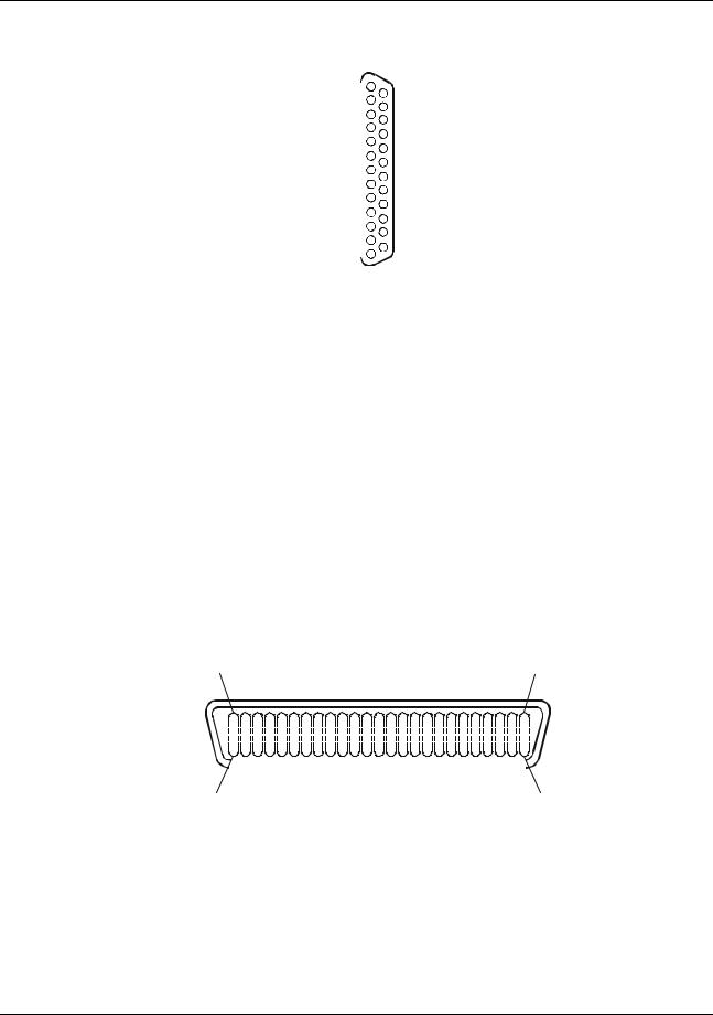
50-Pin Narrow SCSI Port Connector
Position 25 |
|
|
|
|
|
|
|
|
|
|
|
|
|
|
|
|
|
|
|
|
|
|
|
|
|
|
|
|
|
|
|
|
|
|
|
|
|
|
Position 1 |
|||||||||||
|
|
|
|
|
|
|
|
|
|
|
|
|
|
|
|
|
|
|
|
|
|
|
|
|
|
|
|
|
|
|
|
|
|
|
|
|
|
|
|
|
|
|
|
|
|
|
|
|
|
|
|
|
|
|
|
|
|
|
|
|
|
|
|
|
|
|
|
|
|
|
|
|
|
|
|
|
|
|
|
|
|
|
|
|
|
|
|
|
|
|
|
|
|
|
|
|
|
|
|
|
|
|
|
|
|
|
|
|
|
|
|
|
|
|
|
|
|
|
|
|
|
|
|
|
|
|
|
|
|
|
|
|
|
|
|
|
|
|
|
|
|
|
|
|
|
|
|
|
|
|
|
|
|
|
|
|
|
|
|
|
|
|
|
|
|
|
|
|
|
|
|
|
|
|
|
|
|
|
|
|
|
|
|
|
|
|
|
|
|
|
|
|
|
|
|
|
|
|
|
|
|
|
|
|
|
|
|
|
|
|
|
|
|
|
|
|
|
|
|
|
|
|
|
|
|
|
|
|
|
|
|
|
|
|
|
|
|
|
|
|
|
|
|
|
|
|
|
|
|
|
|
|
|
|
|
|
|
|
|
|
|
|
|
|
|
|
|
|
|
|
|
|
|
|
|
|
|
|
|
|
|
|
|
|
|
|
|
|
|
|
|
|
|
|
|
|
|
|
|
|
|
|
|
|
|
|
Position 50 |
|
Position 26 |
|
|
SCSI Port Connector Pinouts |
|
|
|
50-Pin Narrow SCSI Port Connector Pinouts |
|
|
|
|
Pin Number |
Signal Description |
Pin Number |
|
Signal Description |
|
|
|
|
|
1-11 |
Ground |
37 |
|
Reserved |
|
|
|
|
|
12 |
Reserved |
38 |
|
Termpwr |
13 |
Open |
39 |
|
Reserved |
19
Chapter 2 System Information
Pin Number |
Signal Description |
|
Pin Number |
|
Signal Description |
|
|
|
|
|
|
|
|
14 |
Reserved |
|
40 |
|
Ground |
|
15-25 |
|
Ground |
|
41 |
|
-ATN |
|
|
|
|
|
|
|
26 |
|
-DB(0)7 |
|
42 |
|
Ground |
27 |
|
-DB(1) |
|
43 |
|
-BSY |
28 |
|
-DB(2) |
|
44 |
|
-ACK |
|
|
|
|
|
|
|
29 |
|
-DB(3) |
|
45 |
|
-RST |
30 |
|
-DB(4) |
|
46 |
|
-MSG |
31 |
|
-DB(5) |
|
47 |
|
-SEL |
|
|
|
|
|
|
|
32 |
|
-DB(6) |
|
48 |
|
-C/D |
33 |
|
-DB(7) |
|
49 |
|
-REQ |
34 |
|
-DB(P) |
|
50 |
|
-I/O |
|
|
|
|
|
|
|
35-36 |
Ground |
|
|
|
|
|
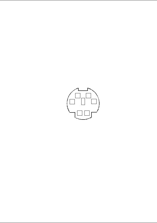
Mini-DIN Connectors |
|
|
|
|
|
|
|
6 |
5 |
|
|
||
|
4 |
|
3 |
|
|
|
|
2 |
1 |
|
|
||
|
Mini-DIN Connector Pinouts for the Mouse and Keyboard |
|
||||
Mini-DIN Connector Pinouts for the Mouse and Keyboard |
|
|||||
Pin Number |
|
|
|
Signal Description |
|
|
|
|
|
|
|
|
|
1 |
|
Data signal |
|
|
|
|
2 |
|
Not used |
|
|
|
|
3 |
|
Ground |
|
|
|
|
4 |
|
Power (+5 V dc) |
|
|
|
|
5 |
|
Clock signal |
|
|
|
|
6 |
|
Not used |
|
|
|
|
20
Chapter 2 |
System Information |
|
|
|
|
|
|
|
|
|
|
|
|
|
|
|
|
|
|
|
|
|
|
|
|
|
|
|
|
|
|
|
|
|
|
|
|
|
|
|
|
|
|
|
|
|
|
|
|
1 |
|
8 |
|
||||||||
|
LAN Connector |
||||||||||
|
|
|
|
|
|
|
|
|
|||
LAN Connector Pin Number |
|
|
|
|
|
|
|
Signal Description |
|||
|
|
|
|
|
|||||||
1 |
|
|
|
Data signal |
|||||||
2 |
|
|
|
Not used |
|||||||
3 |
|
|
|
Ground |
|||||||
4 |
|
|
|
Power (+5 V dc) |
|||||||
5 |
|
|
|
Clock signal |
|||||||
6 |
|
|
|
Not used |
|||||||
Memory Guidelines
The standard memory configuration is 256 MB of interleaved memory, one 128 MB DIMM in socket 1A and one 128 MB DIMM in socket 1B. Expansion is accomplished by adding pairs of equal size DIMMs in stipulated slots up to the maximum configuration of 8 GB.
1A
2A
3A 4A
DIMM
Slots
1B 2B
3B
4B 

 S1
S1
DIMM slots on System Board
lAdd paired DIMMs of these sizes:
◊128 MB
◊256 MB
◊512 MB
◊1 GB
lMemory of equal size must be added in pairs.
lYou can mix DIMM sizes. For example, you may place a 1 GB DIMM pair next to a 128 MB DIMM pair.
lAdd paired memory in any order to the eight slots.
21
Chapter 2 |
System Information |
lMaximum configuration is 8 GB.
lDo not rock the DIMM into place, but apply firm and even pressure until it is seated in the socket.
lUse only HP-supported DIMMs.
The installation procedure is the same for the rack-mount and the pedestal HP NetServers once you gain access to the system board assembly. While you can perform memory installation in the rack or in the pedestal, it is recommended that you remove the system board assembly in order to install components. If you install memory without removing the system board assembly, the DIMM slots region of the system board is accessible when the bottom cover of the LH 6000r is removed and the left cover of the LH 6000 is removed.
CAUTION Wear a wrist-strap and use a static-dissipating work surface connected to the chassis when handling components. Ensure the metal of the wrist strap contacts your skin.
Mass Storage Guidelines
This HP NetServer has a flexible mass storage system. You can install up to six hot-swap devices in the primary hot-swap mass storage cage and you can install an additional six hot-swap devices in the optional, secondary cage.
Flexible disk drive
CD-ROM drive
Non-hot-swap drive shelves
Secondary |
Primary |
hotswap |
hot-swap |
cage |
cage |
The mass storage system includes several standard pre-installed devices:
•A flexible disk drive is installed in Shelf 1.
•An IDE CD-ROM drive is installed in Shelf 2.
•A single hot-swap Ultra-2 SCSI hard disk drive is installed in the primary hot-swap mass storage cage.
The HP NetServers support two classes of mass storage devices:
22

Chapter 2 |
System Information |
•Non-hot-swap, single-ended SCSI devices installed in the two empty trays adjacent to the CDROM drive
•Hot-swap Ultra-2 SCSI hard disk drives installed in the hot-swap mass storage cages
Use only high-performance, Ultra-2, hot-swap drives in the integral hot-swap mass storage cages.
You can add any Ultra/Wide, single-ended SCSI device in the non-hot-swap shelves, such as a removable hard disk or a tape backup drive. This table lists supported SCSI devices:
Location |
Drive Type |
|
|
Hot-swap Mass Storage |
9.1, 18.2 or 36 GB, Ultra-2, 7200 or 10000 rpm drives (up to 35W) |
Shelves |
|
Non-Hot-Swap Shelves |
9.1 or 18.2 GB Ultra/Wide or Single-Ended SCSI Drives, 7200 or 10000 rpm |
|
drives |
|
DAT backup systems with SCSI DDS3, or DLT Tape Drives |
Accessory Board Guidelines
To install accessory boards, during initial installations, into the I/O board, perform the following procedures. The I/O board is under the top cover of the LH 6000r and under the left cover of the LH 6000.
lUse the respective NOS software utility to
◊Ensure the correct software drivers for the PCI board are loaded
◊Verify correct operation
◊Shut down power to hot plug slots
CAUTION Do not attempt to install or remove non-hot plug PCI boards with the HP NetServer in any kind of sleep state, or a system crash or hang may occur.
lSlots 1, 2, 3, and 4 are non-hot plug; slots 5, 6, 7, and 8 are hot plug.
lFor optimal performance, add PCI boards to slots 7 and 8, which at 66 MHz and 64 bit, are the fastest.
lConsider the boot priority prior to installing accessory boards, but after configuring the HP NetServer.
lSome accessory board outputs may exceed U.S. National Electrical code (NFPA 70) Class 2 or power source limits and must use appropriate interconnecting cabling in accordance with the National Electrical Code. (All Hewlett Packard boards comply with Class 2.)
lYou can configure the HP NetServer to boot from a PCI-based DAC inserted into a PCI slot. Use the Symbios Configuration Utility to select a different PCI slot when scanning for boot devices.
lSlots 7 and 8 accept universal boards. Universal boards automatically switch to accept power from a +5.0 or +3.3 VDC.
Hot Addition and Replacement of Hot Plug PCI Boards
The PCI Hot Plug option is NOS-dependent. To use the Hot Plug option, the PCI board must have a hot plug compliant driver and a Hot Plug Utility for the respective NOS. The Hot Plug Utility is used to turn power off/on to the PCI slot, while the HP NetServer continues to operate normally.
23

Chapter 2 System Information
NOTE |
Hot Removal or online deletion of an adapter board and reconfiguring of that |
|
adapter from the HP NetServer is not supported. |
Refer to the PCI Hot Plug Replacement procedures in HP NetServer Navigator CD-ROM for the NOS you are using.
Online Replacement, Hot Swapping, of a PCI Adapter
NOTE |
You can Hot Swap an adapter only if it is the passive adapter, or inactive adapter of |
|
a fault-tolerant pair. |
For more current PCI Hot Plug information and PCI Hot Plug drivers, go to:
http://www.hp.com/cposupport/
Select your product and download the latest software. PCI hot plug drivers are in the SCSI section.
Remote Control (Top Tools) Board
The HP Remote Control board supports HP TopTools software and comes installed from the factory in PCI slot 2, due to its boot order (Bus 5) and a required cable connection to the I/O board. The I2C cable for the HP TopTools Remote Control card is inserted into connector J1F1 on the I/O board.
HP NetRAID Guidelines
This HP NetServer contains an embedded dual-channel RAID controller, which puts the power of the HP NetRAID series of disk array controllers in the HP NetServer.
HP NetRAID technology lets you link multiple hard disk drives together to provide faster access and/or increased data reliability. With the embedded RAID controller, you can configure your linked drives as RAID (Redundant Array of Independent Disks).
Disk drives in the hot-swap mass storage cage may be used as either standard mass storage, or configured together as a RAID array.
This HP NetServer is shipped with SCSI A channel enabled as a RAID channel, and the included hot-swap drive is not configured. You can either disable SCSI A channel as a RAID channel, or configure the drive(s) in the hot-swap cage as a RAID array.
To disable SCSI A channel:
•Exclude SCSI A channel from the embedded RAID controller, as follows:
1.Restart the HP NetServer.
2.When you see the message "Press [F2] to enter SETUP" on the monitor, press the [F2] function key.
3.When the Setup Utility menu appears, use the up and down arrow keys to highlight "Included SCSI A Channel Yes]."
4.Use the +/- keys to change it to "Included SCSI A Channel [No]."
5.Press the F10 function key to save and exit.
6.Answer "Yes" to the question, "Save configuration and exit now?" The HP NetServer will start up again, and HP Navigator will restart.
24
 Loading...