


 Loading...
HP LaserJet 3015, 3020, and 3030 all-in-one
Service Manual
Copyright Information
© Copyright 2004 Hewlett-Packard
Development Company, L.P.
Reproduction, adaptation or translation without prior written permission is prohibited, except as allowed under the copyright laws.
The information contained herein is subject to change without notice.
The only warranties for HP products and services are set forth in the express warranty statements accompanying such products and services. Nothing herein should be construed as constituting an additional warranty. HP shall not be liable for technical or editorial errors or omissions contained herein.
Part number Q2665-90901
Edition 1, 01/2004
Trademark Credits
Adobe® and PostScript® are trademarks of Adobe Systems Incorporated.
Microsoft®, Windows®, and Windows NT® are U.S. registered trademarks of Microsoft Corporation.
Safety Information
WARNING!
Potential Shock Hazard
Always follow basic safety precautions when using this product to reduce risk of injury from fire or electric shock.
Read and understand all instructions in the user guide.
Observe all warnings and instructions marked on the product.
Use only a grounded electrical outlet when connecting the HP LaserJet 3015, 3020, and 3030 all-in-one products to a power source. If you don't know whether the outlet is grounded, check with a qualified electrician.
Do not touch the contacts on the end of any of the sockets on the HP LaserJet 3015, 3020, or 3030 all-in-one. Replace damaged cords immediately.
Unplug this product from wall outlets before cleaning.
Do not install or use this product near water or when you are wet.
Install the product securely on a stable surface.
Install the product in a protected location where no one can step on or trip over the power cord and the power cord will not be damaged.
If the product does not operate normally, see the online user guide.
Refer all servicing questions to qualified personnel.
Table of contents
1 Product Information |
|
Product configurations............................................................................................................... |
2 |
HP LaserJet 3015, 3020, and 3030 all-in-one products...................................................... |
2 |
HP LaserJet 3015 all-in-one product................................................................................... |
3 |
HP LaserJet 3020/3030 all-in-one product.......................................................................... |
3 |
Product features ........................................................................................................................ |
4 |
Overview of products................................................................................................................. |
5 |
Hardware components........................................................................................................ |
5 |
Product identification.................................................................................................................. |
7 |
Model and serial numbers................................................................................................... |
7 |
Product specifications................................................................................................................ |
8 |
Physical specifications......................................................................................................... |
8 |
Environmental specifications (all models)........................................................................... |
8 |
HP LaserJet 3015 performance specifications.................................................................... |
8 |
HP LaserJet 3020/3030 performance specifications......................................................... |
10 |
Electrical specifications (all models).................................................................................. |
12 |
Acoustic emissions (all models)........................................................................................ |
12 |
Skew specifications (all models)....................................................................................... |
12 |
HP LaserJet 3030 fax capabilities..................................................................................... |
13 |
HP LaserJet 3015, 3020, and 3030 all-in-one battery....................................................... |
14 |
Warranty statement.................................................................................................................. |
15 |
HP’s Premium Protection print-cartridge warranty................................................................... |
16 |
Extended warranty................................................................................................................... |
17 |
Print-cartridge information ....................................................................................................... |
18 |
Refilled print cartridges .................................................................................................... |
18 |
HP LaserJet printing supplies ........................................................................................... |
18 |
HP Printing Supplies Returns and Recycling Program information.................................. |
18 |
FCC regulations....................................................................................................................... |
20 |
Telephone Consumer Protection Act (United States).............................................................. |
22 |
IC CS-03 requirements............................................................................................................ |
23 |
Declaration of Conformity ........................................................................................................ |
24 |
Safety statements.................................................................................................................... |
25 |
Laser safety statement...................................................................................................... |
25 |
Canada DOC regulations.................................................................................................. |
25 |
Laser statement for Finland............................................................................................... |
26 |
Korean EMI statement....................................................................................................... |
26 |
Australian EMC requirements............................................................................................ |
26 |
Regulatory information for the European Union countries/regions ......................................... |
27 |
2 Operation |
|
Operating environment............................................................................................................. |
30 |
Identifying the control-panel components................................................................................ |
31 |
Control-panel menu structure.................................................................................................. |
33 |
To use the control-panel buttons....................................................................................... |
33 |
To print the control-panel menu structure......................................................................... |
33 |
ENWW |
iii |
Product media specifications .................................................................................................. |
37 |
Main input tray (all models) .............................................................................................. |
37 |
Automatic document feeder (ADF) specifications............................................................. |
38 |
To gain access to the optimizing feature........................................................................... |
38 |
Guidelines for using media....................................................................................................... |
39 |
Paper and transparencies ................................................................................................ |
39 |
Common media problems table........................................................................................ |
39 |
Labels................................................................................................................................ |
40 |
Envelopes.......................................................................................................................... |
40 |
Card stock and heavy media ............................................................................................ |
41 |
Loading media ......................................................................................................................... |
43 |
Media input tray ................................................................................................................ |
43 |
Priority input tray ............................................................................................................... |
43 |
Specific types of media ..................................................................................................... |
43 |
Media information for ADF originals ................................................................................. |
43 |
Media information for the flatbed (HP LaserJet 3020 and 3030) ..................................... |
44 |
Loading originals to copy or scan...................................................................................... |
44 |
Loading originals into the LJ 3020 and 3030 ADF input tray............................................ |
45 |
Loading originals onto the LJ 3020 and 3030 flatbed scanner......................................... |
46 |
3 Maintenance |
|
Life expectancies of parts that wear ....................................................................................... |
48 |
Scanner calibration ................................................................................................................. |
49 |
Cleaning the product ............................................................................................................... |
50 |
To clean the print path ...................................................................................................... |
50 |
Cleaning the glass............................................................................................................. |
50 |
Cleaning the print-cartridge area............................................................................................. |
54 |
To cleaning the print-cartridge area (all models)............................................................... |
54 |
Cleaning the printer pickup roller (all models)................................................................... |
55 |
Cleaning the printer separation pad (all models).............................................................. |
56 |
User replaceable parts............................................................................................................. |
57 |
Printer pickup roller (all models)........................................................................................ |
57 |
Printer separation pad (all models)................................................................................... |
59 |
Printer main input tray (all models).................................................................................... |
60 |
HP LaserJet 3015 ADF pickup roller ................................................................................ |
61 |
HP LaserJet 3015 ADF separation pad set....................................................................... |
62 |
HP LaserJet 3015 ADF input tray...................................................................................... |
62 |
HP LaserJet 3015 ADF output bin..................................................................................... |
63 |
HP LaserJet 3020 and 3030 ADF pickup roller................................................................. |
63 |
HP LaserJet 3020 and 3030 ADF separation pad............................................................ |
66 |
HP LaserJet 3020 and 3030 control-panel bezel.............................................................. |
66 |
4 Operational overview |
|
Basic functions (all models) .................................................................................................... |
70 |
Basic sequence of operation ................................................................................................... |
71 |
Formatter system .................................................................................................................... |
75 |
Central processing unit ..................................................................................................... |
75 |
Line interface unit (HP LaserJet 3015 and 3030 only) ..................................................... |
75 |
Standard boot process ..................................................................................................... |
75 |
RAM .................................................................................................................................. |
76 |
Parallel interface or universal serial bus (USB) interface ................................................. |
76 |
Control panel .................................................................................................................... |
76 |
EconoMode ....................................................................................................................... |
76 |
MEt .................................................................................................................................... |
77 |
Enhanced I/O .................................................................................................................... |
77 |
iv |
ENWW |
PJL overview .................................................................................................................... |
77 |
Printer functions (all models)................................................................................................... |
78 |
Engine control system (engine control unit and power-supply assembly)........................ |
78 |
Image-formation system.................................................................................................... |
83 |
Print cartridge.................................................................................................................... |
84 |
Printer paper-feed system................................................................................................. |
84 |
Jam detection in the printer .............................................................................................. |
85 |
HP LaserJet 3015 all-in-one unique components.................................................................... |
87 |
Basic operation.................................................................................................................. |
87 |
HP LaserJet 3020 and 3030 all-in-one unique components.................................................... |
93 |
Scanner and ADF functions and operation ...................................................................... |
93 |
Fax functions and operation (HP LaserJet 3015 and 3030 only) ........................................... |
96 |
PSTN operation ................................................................................................................ |
96 |
The fax subsystem ........................................................................................................... |
96 |
Formatter in the fax subsystem ........................................................................................ |
96 |
LIU in the fax subsystem .................................................................................................. |
96 |
Fax page storage in flash memory ................................................................................... |
99 |
5 Removal and replacement |
|
Removal and replacement strategy....................................................................................... |
103 |
Required tools.................................................................................................................. |
103 |
Before performing service............................................................................................... |
103 |
After performing service.................................................................................................. |
104 |
Parts removal order......................................................................................................... |
104 |
HP LaserJet 3015 all-in-one.................................................................................................. |
107 |
Link assemblies and scanner support frame springs...................................................... |
107 |
Scanner side covers........................................................................................................ |
110 |
Separation-pad set.......................................................................................................... |
111 |
Control-panel bezel......................................................................................................... |
112 |
Control-panel assembly................................................................................................... |
113 |
Media lever and media lever torsion spring.................................................................... |
114 |
Separation pad assembly................................................................................................ |
115 |
Scanner assembly........................................................................................................... |
118 |
Scanner assembly top cover........................................................................................... |
126 |
Top-cover assembly........................................................................................................ |
129 |
Pickup roller .................................................................................................................... |
130 |
White platen..................................................................................................................... |
131 |
HP LaserJet 3020 and 3030 all-in-one.................................................................................. |
133 |
ADF input tray.................................................................................................................. |
133 |
Flatbed lid........................................................................................................................ |
134 |
Link assemblies and scanner support frame springs...................................................... |
136 |
Control-panel bezel......................................................................................................... |
139 |
Control-panel assembly................................................................................................... |
139 |
ADF separation pad ........................................................................................................ |
140 |
ADF input-tray flag........................................................................................................... |
141 |
ADF pickup roller ............................................................................................................ |
142 |
ADF scanner glass.......................................................................................................... |
143 |
Scanner assembly........................................................................................................... |
145 |
Printer (product base)............................................................................................................ |
153 |
Printer separation pad..................................................................................................... |
154 |
Print cartridge.................................................................................................................. |
154 |
Printer pickup roller.......................................................................................................... |
156 |
Media input tray............................................................................................................... |
158 |
Transfer roller.................................................................................................................. |
159 |
Printer side covers........................................................................................................... |
161 |
ENWW |
v |
Print-cartridge door.......................................................................................................... |
163 |
Rear cover and fuser cover............................................................................................. |
164 |
Front cover....................................................................................................................... |
165 |
Installing the scanner cushions....................................................................................... |
167 |
Speaker assembly........................................................................................................... |
168 |
Power supply................................................................................................................... |
169 |
Formatter and line interface unit (LIU)............................................................................. |
171 |
Scanner support frame ................................................................................................... |
175 |
Engine controller unit....................................................................................................... |
177 |
Laser/scanner assembly.................................................................................................. |
181 |
Main motor....................................................................................................................... |
182 |
Fuser................................................................................................................................ |
184 |
Paper-pickup assembly................................................................................................... |
186 |
6 Troubleshooting |
|
Basic troubleshooting ............................................................................................................ |
188 |
Control-panel messages ....................................................................................................... |
193 |
Alert and warning messages .......................................................................................... |
193 |
Critical error messages ................................................................................................... |
201 |
Event-log codes............................................................................................................... |
204 |
Solving image-quality problems ............................................................................................ |
206 |
Checking the print cartridge ............................................................................................ |
206 |
Solving print image-quality problems ............................................................................. |
206 |
Solving scanning (copying) image-quality problems ............................................................ |
216 |
Repetitive image defect ruler ................................................................................................ |
222 |
Solving paper-feed problems ................................................................................................ |
223 |
Jams occur in the printer................................................................................................. |
223 |
Solving print paper-feed problems ................................................................................. |
225 |
Jams occur in the automatic document feeder (ADF)..................................................... |
227 |
Solving scanner (copier) paper-feed problems .............................................................. |
229 |
Solving problems with digital subscriber line (DSL) connections.......................................... |
231 |
Connecting additional devices......................................................................................... |
231 |
Functional checks ................................................................................................................. |
235 |
Control-panel test............................................................................................................ |
235 |
Half self-test functional check ......................................................................................... |
235 |
Drum rotation functional check ...................................................................................... |
237 |
High-voltage contacts check .......................................................................................... |
238 |
Updating the firmware code................................................................................................... |
240 |
Troubleshooting tools ............................................................................................................ |
241 |
Printing a configuration report, demonstration page, or menu structure ........................ |
241 |
Printing all fax reports at once (HP LaserJet 3015 and 3030 only) ............................... |
241 |
T.30 protocol trace (HP LaserJet 3015 and 3030 only) ................................................. |
241 |
Service-mode functions ......................................................................................................... |
262 |
Secondary service menu ................................................................................................ |
262 |
Developer’s menu ........................................................................................................... |
263 |
Adjusting the country/region code parameters................................................................ |
264 |
Soft reset......................................................................................................................... |
265 |
NVRAM init ..................................................................................................................... |
265 |
System settings for localized products............................................................................ |
266 |
Printer job language (PJL) software commands ............................................................ |
268 |
Main wiring ............................................................................................................................ |
269 |
Component locations, HP LaserJet 3015 all-in-one ............................................................. |
272 |
Component locations, HP LaserJet 3020 and 3030 all-in-one.............................................. |
276 |
Component locations, HP LaserJet 3015, 3020 and 3030 printer (product base)................ |
277 |
vi |
ENWW |
7 Parts and diagrams |
|
Ordering parts and supplies .................................................................................................. |
282 |
Parts that wear ................................................................................................................ |
282 |
Parts ............................................................................................................................... |
282 |
World-wide customer support ......................................................................................... |
282 |
Accessories ........................................................................................................................... |
284 |
Common hardware ......................................................................................................... |
284 |
How to use the parts lists and diagrams ........................................................................ |
285 |
HP LaserJet 3015 scanner assembly ................................................................................... |
286 |
HP LaserJet 3020/3030 scanner assembly .......................................................................... |
296 |
HP LaserJet 3015/3020/3030 printer base............................................................................ |
304 |
Alphabetical parts list............................................................................................................. |
320 |
Numerical parts list................................................................................................................. |
326 |
Index |
|
ENWW |
vii |
viii |
ENWW |
List of tables
Table 1-1. |
Physical specifications....................................................................................... |
8 |
Table 1-2. |
Environmental specifications (all models).......................................................... |
8 |
Table 1-3. |
HP LaserJet 3015 performance specifications.................................................. |
8 |
Table 1-4. |
HP LaserJet 3020/3030 performance specifications....................................... |
10 |
Table 1-5. |
Electrical specifications (all models)................................................................ |
12 |
Table 1-6. |
Acoustic emissions (all models)....................................................................... |
12 |
Table 1-7. |
Skew specifications (all models) ..................................................................... |
12 |
Table 1-8. |
HP LaserJet 3030 fax capabilities.................................................................... |
13 |
Table 1-9. |
HP LaserJet 3015, 3020, and 3030 all-in-one battery..................................... |
14 |
Table 2-1. |
Control-panel menu structure.......................................................................... |
33 |
Table 2-2. |
Supported media types.................................................................................... |
37 |
Table 3-1. |
Life expectancies of parts that wear ............................................................... |
48 |
Table 4-1. |
HP LaserJet 3015 basic sequence of operation.............................................. |
71 |
Table 4-2. |
HP LaserJet 3020 and 3030 basic sequence of operation.............................. |
71 |
Table 4-3. |
HP LaserJet 3015, 3020 and 3030 printer (product base) basic |
|
|
sequence of operation...................................................................................... |
73 |
Table 4-4. |
Product startup messages............................................................................... |
76 |
Table 4-5. |
Dc power distribution........................................................................................ |
80 |
Table 6-1. |
Alert and warning messages ........................................................................ |
193 |
Table 6-2. |
Critical error messages.................................................................................. |
201 |
Table 6-3. |
Event-log codes............................................................................................. |
204 |
Table 6-4. |
Fax receive codes.......................................................................................... |
243 |
Table 6-5. |
Fax send codes.............................................................................................. |
248 |
Table 6-6. |
Fax phase sequence (HP LaserJet 3015 and 3030 only)............................. |
254 |
Table 6-7. |
Appropriate responses (HP LaserJet 3015 and 3030 only)........................... |
256 |
Table 6-8. |
Fax abbreviations (HP LaserJet 3015 and 3030 only).................................. |
257 |
Table 6-9. |
System settings.............................................................................................. |
266 |
Table 7-1. |
Technical support websites and related documentation................................ |
282 |
Table 7-2. |
Accessories.................................................................................................... |
284 |
Table 7-3. |
Common fasteners ....................................................................................... |
284 |
Table 7-4. |
Alphabetical parts list..................................................................................... |
320 |
Table 7-5. |
Numerical parts list......................................................................................... |
326 |
ENWW |
ix |
x |
ENWW |
List of figures
Figure 1-1. |
HP LaserJet 3015, 3020, and 3030 all-in-one products.................................... |
2 |
Figure 1-2. |
HP LaserJet 3015 all-in-one hardware components.......................................... |
5 |
Figure 1-3. |
HP LaserJet 3020 all-in-one hardware components.......................................... |
6 |
Figure 1-4. |
HP LaserJet 3030 all-in-one hardware components.......................................... |
6 |
Figure 1-5. |
Sample Identification label (on the back of the product).................................... |
7 |
Figure 1-6. |
Location of additional serial number label......................................................... |
7 |
Figure 2-1. |
HP LaserJet 3015 dimensions......................................................................... |
30 |
Figure 2-2. |
HP LaserJet 3020/3030 dimensions................................................................ |
30 |
Figure 2-3. |
HP LaserJet 3015 all-in-one control panel....................................................... |
31 |
Figure 2-4. |
HP LaserJet 3020 all-in-one control panel....................................................... |
32 |
Figure 2-5. |
HP LaserJet 3030 all-in-one control panel....................................................... |
32 |
Figure 2-6. |
Envelope construction...................................................................................... |
41 |
Figure 2-7. |
Loading the LJ 3015 ADF (1 of 3).................................................................... |
44 |
Figure 2-8. |
Loading the LJ 3015 ADF (2 of 3).................................................................... |
45 |
Figure 2-9. |
Loading the LJ 3015 ADF (3 of 3).................................................................... |
45 |
Figure 2-10. |
Loading the LJ 3020 and 3030 ADF (1 of 2).................................................... |
46 |
Figure 2-11. |
Loading the LJ 3020 and 3030 ADF (2 of 2).................................................... |
46 |
Figure 2-12. Loading the LJ 3020 and 3030 flatbed scanner............................................... |
46 |
|
Figure 3-1. |
Cleaning the LJ 3015 glass.............................................................................. |
51 |
Figure 3-2. |
Cleaning the LJ 3015 white platen................................................................... |
51 |
Figure 3-3. |
Cleaning the LJ 3020 and 3030 glass (1 of 2)................................................. |
52 |
Figure 3-4. |
Cleaning the LJ 3020 and 3030 glass (2 of 2)................................................. |
52 |
Figure 3-5. |
Cleaning the LJ 3020 and 3030 lid backing..................................................... |
52 |
Figure 3-6. |
Cleaning the print-cartridge area (1 of 3)......................................................... |
54 |
Figure 3-7. |
Cleaning the print-cartridge area (2 of 3)......................................................... |
54 |
Figure 3-8. |
Cleaning the print-cartridge area (3 of 3)......................................................... |
55 |
Figure 3-9. |
Cleaning the separation pad............................................................................ |
55 |
Figure 3-10. |
Cleaning the pickup roller (1 of 3).................................................................... |
55 |
Figure 3-11. |
Cleaning the pickup roller (2 of 3).................................................................... |
56 |
Figure 3-12. |
Cleaning the pickup roller (3 of 3).................................................................... |
56 |
Figure 3-13. Cleaning the separation pad (1 of 2)................................................................ |
56 |
|
Figure 3-14. Cleaning the separation pad (2 of 2)................................................................ |
56 |
|
Figure 3-15. |
Replacing the pickup roller (1 of 7).................................................................. |
57 |
Figure 3-16. |
Replacing the pickup roller (2 of 7).................................................................. |
57 |
Figure 3-17. |
Replacing the pickup roller (3 of 7).................................................................. |
57 |
Figure 3-18. |
Replacing the pickup roller (4 of 7).................................................................. |
58 |
Figure 3-19. |
Replacing the pickup roller (5 of 7).................................................................. |
58 |
Figure 3-20. |
Replacing the pickup roller (6 of 7) ................................................................. |
58 |
Figure 3-21. |
Replacing the pickup roller (7 of 7) ................................................................. |
58 |
Figure 3-22. |
Replacing the printer separation pad (1 of 5).................................................. |
59 |
Figure 3-23. |
Replacing the printer separation pad (2 of 5).................................................. |
59 |
Figure 3-24. |
Replacing the printer separation pad (3 of 5).................................................. |
60 |
Figure 3-25. |
Replacing the printer separation pad (4 of 5) ................................................. |
60 |
Figure 3-26. |
Replacing the printer separation pad (5 of 5) ................................................. |
60 |
Figure 3-27. Remove the media input tray (1 of 2)............................................................... |
61 |
|
Figure 3-28. |
Remove the paper pickup tray (2 of 2)............................................................. |
61 |
ENWW |
xi |
Figure 3-29. |
Remove the separation pad............................................................................. |
62 |
Figure 3-30. |
Replacing the ADF input tray........................................................................... |
63 |
Figure 3-31. |
Replacing the ADF output bin.......................................................................... |
63 |
Figure 3-32. |
Replacing the ADF pickup-roller assembly (1 of 9) ........................................ |
63 |
Figure 3-33. |
Replacing the ADF pickup-roller assembly (2 of 9) ........................................ |
64 |
Figure 3-34. |
Replacing the ADF pickup-roller assembly (3 of 9) ........................................ |
64 |
Figure 3-35. |
Replacing the ADF pickup-roller assembly (4 of 9) ........................................ |
64 |
Figure 3-36. |
Replacing the ADF pickup-roller assembly (5 of 9) ........................................ |
64 |
Figure 3-37. |
Replacing the ADF pickup-roller assembly (6 of 9) ........................................ |
65 |
Figure 3-38. |
Replacing the ADF pickup-roller assembly (7 of 9) ........................................ |
65 |
Figure 3-39. |
Replacing the ADF pickup-roller assembly (8 of 9) ........................................ |
65 |
Figure 3-40. |
Replacing the ADF pickup-roller assembly (9 of 9) ........................................ |
65 |
Figure 3-41. |
Remove the separation pad............................................................................. |
66 |
Figure 3-42. |
Replacing the control-panel bezel (1 of 4)....................................................... |
66 |
Figure 3-43. |
Replacing the control-panel bezel (2 of 4)....................................................... |
67 |
Figure 3-44. |
Replacing the control-panel bezel (3 of 4)....................................................... |
67 |
Figure 3-45. |
Replacing the control-panel bezel (4 of 4)....................................................... |
67 |
Figure 4-1. |
Product configuration ...................................................................................... |
70 |
Figure 4-2. |
HP LaserJet 3015, 3020, and 3030 printer (product base) timing |
|
|
diagram ......................................................................................................... |
74 |
Figure 4-3. |
Printer functional block diagram....................................................................... |
78 |
Figure 4-4. |
Laser/scanner operation.................................................................................. |
80 |
Figure 4-5. |
High-voltage power supply circuit.................................................................... |
82 |
Figure 4-6. |
Image-formation block diagram ...................................................................... |
83 |
Figure 4-7. |
Printer paper path ........................................................................................... |
85 |
Figure 4-8. |
Basic operation block diagram......................................................................... |
87 |
Figure 4-9. |
HP LaserJet 3015 optical and feed systems................................................... |
88 |
Figure 4-10. |
HP LaserJet 3015 feed control (1 of 2)............................................................ |
89 |
Figure 4-11. |
HP LaserJet 3015 feed control (2 of 2)............................................................ |
90 |
Figure 4-12. |
HP LaserJet 3015 optical system (1 of 2)........................................................ |
91 |
Figure 4-13. |
HP LaserJet 3015 optical system (2 of 2)........................................................ |
92 |
Figure 4-14. |
HP LaserJet 3020 and 3030 optical system ................................................... |
93 |
Figure 4-15. |
HP LaserJet 3020 and 3030 ADF path ........................................................... |
95 |
Figure 5-1. |
HP LaserJet 3015, 3020, and 3030 products................................................ |
104 |
Figure 5-2. |
Parts removal order for the HP LaserJet 3015 all-in-one.............................. |
105 |
Figure 5-3. |
Parts removal order for the HP LaserJet 3020 and 3030 all-in-one ............. |
105 |
Figure 5-4. |
Parts removal order for the printer (product base, all models)...................... |
106 |
Figure 5-5. |
Parts removal order HP LaserJet 3015 scanner assembly........................... |
107 |
Figure 5-6. |
Remove the link assemblies and scanner support frame springs (1 of 4) .... |
108 |
Figure 5-7. |
Remove the link assemblies and scanner support frame springs (2 of 4)..... |
108 |
Figure 5-8. |
Remove the link assemblies and scanner support frame springs (3 of 4)..... |
109 |
Figure 5-9. |
Remove the link assemblies and scanner support frame springs (4 of 4)..... |
109 |
Figure 5-10. |
Remove the scanner side covers (1 of 3)...................................................... |
110 |
Figure 5-11. |
Remove the scanner side covers (2 of 3)...................................................... |
110 |
Figure 5-12. |
Remove the scanner side covers (3 of 3)...................................................... |
111 |
Figure 5-13. |
Remove the separation pad........................................................................... |
112 |
Figure 5-14. |
Remove the control-panel bezel (1 of 3)........................................................ |
112 |
Figure 5-15. |
Remove the control-panel bezel (2 of 3)........................................................ |
113 |
Figure 5-16. |
Remove the control-panel bezel (3 of 3)........................................................ |
113 |
Figure 5-17. |
Remove the control-panel assembly (1 of 2)................................................. |
114 |
Figure 5-18. |
Remove the control-panel assembly (2 of 2)................................................. |
114 |
Figure 5-19. |
Remove the media lever and media lever torsion spring (1 of 2).................. |
115 |
Figure 5-20. |
Remove the media lever and media lever torsion spring (2 of 2).................. |
115 |
Figure 5-21. |
Remove the separation pad assembly (1 of 3).............................................. |
116 |
Figure 5-22. |
Remove the separation pad assembly (2 of 3).............................................. |
117 |
Figure 5-23. |
Remove the separation pad assembly (3 of 3).............................................. |
117 |
xii |
ENWW |
Figure 5-24. Remove the scanner assembly (1 of 15)....................................................... |
118 |
Figure 5-25. Remove the scanner assembly (2 of 15)....................................................... |
118 |
Figure 5-26. Remove the scanner assembly (3 of 15)....................................................... |
119 |
Figure 5-27. Remove the scanner assembly (4 of 15)....................................................... |
119 |
Figure 5-28. Remove the scanner assembly (5 of 15) ...................................................... |
120 |
Figure 5-29. Remove the scanner assembly (6 of 15)....................................................... |
120 |
Figure 5-30. Remove the scanner assembly (7 of 15)....................................................... |
121 |
Figure 5-31. Remove the scanner assembly (8 of 15)....................................................... |
121 |
Figure 5-32. Remove the scanner assembly (9 of 15)....................................................... |
122 |
Figure 5-33. Remove the scanner assembly (10 of 15)..................................................... |
122 |
Figure 5-34. Remove the scanner assembly (11 of 15) .................................................... |
123 |
Figure 5-35. Remove the scanner assembly (12 of 15) .................................................... |
124 |
Figure 5-36. Remove the scanner assembly (13 of 15)..................................................... |
125 |
Figure 5-37. Remove the scanner assembly (14 of 15)..................................................... |
125 |
Figure 5-38. Remove the scanner assembly (15 of 15)..................................................... |
126 |
Figure 5-39. Remove the scanner assembly top cover (1 of 4)......................................... |
127 |
Figure 5-40. Remove the scanner assembly top cover (2 of 4)......................................... |
127 |
Figure 5-41. Remove the scanner assembly top cover (3 of 4)......................................... |
128 |
Figure 5-42. Remove the scanner assembly top cover (4 of 4) ........................................ |
128 |
Figure 5-43. Reinstalling the scanner assembly top cover................................................ |
129 |
Figure 5-44. Align the scanner assembly top cover and base........................................... |
129 |
Figure 5-45. Remove the top-cover assembly (1 of 2)....................................................... |
130 |
Figure 5-46. Remove the top-cover assembly (2 of 2) ...................................................... |
130 |
Figure 5-47. Remove the pickup roller (1 of 2)................................................................... |
131 |
Figure 5-48. Remove the pickup roller (2 of 2)................................................................... |
131 |
Figure 5-49. Remove the white platen (1 of 2)................................................................... |
132 |
Figure 5-50. Remove the white platen (2 of 2) .................................................................. |
132 |
Figure 5-51. Parts removal order HP LaserJet 3020 and 3030 scanner assembly........... |
133 |
Figure 5-52. Remove the ADF input tray............................................................................ |
133 |
Figure 5-53. Remove the flatbed lid (1 of 5) ...................................................................... |
134 |
Figure 5-54. ADF cover correctly installed......................................................................... |
134 |
Figure 5-55. Remove the flatbed lid (2 of 5)....................................................................... |
135 |
Figure 5-56. Remove the flatbed lid (3 of 5)....................................................................... |
135 |
Figure 5-57. Remove the flatbed lid (4 of 5)....................................................................... |
136 |
Figure 5-58. Remove the flatbed lid (5 of 5)....................................................................... |
136 |
Figure 5-59. Remove the link assemblies and scanner support frame springs (1 of 4)..... |
137 |
Figure 5-60. Remove the link assemblies and scanner support frame springs (2 of 4)..... |
137 |
Figure 5-61. Remove the link assemblies and scanner support frame springs (3 of 4)..... |
138 |
Figure 5-62. Remove the link assemblies and scanner support frame springs (4 of 4)..... |
138 |
Figure 5-63. Remove the control-panel bezel ................................................................... |
139 |
Figure 5-64. Remove the control panel assembly (1 of 2)................................................. |
139 |
Figure 5-65. Remove the control panel assembly (2 of 2) ................................................ |
140 |
Figure 5-66. Remove the separation pad........................................................................... |
140 |
Figure 5-67. Remove the ADF input-tray flag..................................................................... |
141 |
Figure 5-68. Correct positioning of the ADF input-tray spring ........................................... |
141 |
Figure 5-69. Remove the ADF pickup roller (1 of 2).......................................................... |
142 |
Figure 5-70. Remove the ADF pickup roller (2 of 2).......................................................... |
142 |
Figure 5-71. Remove the ADF scanner glass (1 of 3)........................................................ |
143 |
Figure 5-72. Remove the ADF scanner glass (2 of 3)........................................................ |
143 |
Figure 5-73. Remove the ADF scanner glass (3 of 3)........................................................ |
144 |
Figure 5-74. Install the ADF scanner glass........................................................................ |
144 |
Figure 5-75. Remove the scanner assembly (1 of 13)....................................................... |
145 |
Figure 5-76. Remove the scanner assembly (2 of 13) ...................................................... |
145 |
Figure 5-77. Remove the scanner assembly (3 of 13)....................................................... |
146 |
Figure 5-78. Remove the scanner assembly (4 of 13)....................................................... |
146 |
Figure 5-79. Remove the scanner assembly (5 of 13)....................................................... |
147 |
ENWW |
xiii |
Figure 5-80. |
Remove the scanner assembly (6 of 13)....................................................... |
147 |
Figure 5-81. |
Remove the scanner assembly (7 of 13)....................................................... |
148 |
Figure 5-82. |
Remove the scanner assembly (8 of 13)....................................................... |
148 |
Figure 5-83. |
Remove the scanner assembly (9 of 13)....................................................... |
149 |
Figure 5-84. |
Remove the scanner assembly (10 of 13) .................................................... |
150 |
Figure 5-85. |
Remove the scanner assembly (11 of 13) .................................................... |
151 |
Figure 5-86. |
Remove the scanner assembly (12 of 13)..................................................... |
151 |
Figure 5-87. |
Remove the scanner assembly (13 of 13)..................................................... |
152 |
Figure 5-88. |
Parts removal order for the printer (product base, all models)...................... |
153 |
Figure 5-89. |
Remove the printer separation pad (1 of 2)................................................... |
154 |
Figure 5-90. |
Remove the printer separation pad (2 of 2)................................................... |
154 |
Figure 5-91. |
Remove the print cartridge (1 of 2)................................................................ |
155 |
Figure 5-92. |
Remove the print cartridge (2 of 2)................................................................ |
155 |
Figure 5-93. |
Remove the printer pickup roller (1 of 5)....................................................... |
156 |
Figure 5-94. |
Remove the printer pickup roller (2 of 5)....................................................... |
156 |
Figure 5-95. |
Remove the printer pickup roller (3 of 5)....................................................... |
157 |
Figure 5-96. |
Remove the printer pickup roller (4 of 5)....................................................... |
157 |
Figure 5-97. |
Remove the printer pickup roller (5 of 5)....................................................... |
158 |
Figure 5-98. Remove the media input tray (1 of 3)............................................................. |
158 |
|
Figure 5-99. Remove the media input tray (2 of 3)............................................................. |
159 |
|
Figure 5-100. |
Remove the media input tray (3 of 3)............................................................. |
159 |
Figure 5-101. |
Remove the transfer roller (1 of 3)................................................................. |
160 |
Figure 5-102. |
Remove the transfer roller (2 of 3)................................................................. |
160 |
Figure 5-103. |
Remove the transfer roller (3 of 3)................................................................. |
161 |
Figure 5-104. |
Remove the printer side covers (1 of 3)......................................................... |
161 |
Figure 5-105. |
Remove the printer side covers (2 of 3) ........................................................ |
162 |
Figure 5-106. |
Remove the printer side covers (2 of 3) ........................................................ |
162 |
Figure 5-107. |
Remove the printer side covers (3 of 3)......................................................... |
163 |
Figure 5-108. |
Remove the print-cartridge door (1 of 2)........................................................ |
163 |
Figure 5-109. |
Remove the print-cartridge door (2 of 2)........................................................ |
164 |
Figure 5-110. |
Remove the rear cover and fuser cover (1 of 3)............................................ |
164 |
Figure 5-111. |
Remove the rear cover and fuser cover (2 of 3)............................................ |
165 |
Figure 5-112. |
Remove the rear cover and fuser cover (3 of 3)............................................ |
165 |
Figure 5-113. |
Remove the front cover (1 of 3)..................................................................... |
166 |
Figure 5-114. |
Remove the front cover (2 of 3)..................................................................... |
166 |
Figure 5-115. |
Remove the front cover (3 of 3)..................................................................... |
167 |
Figure 5-116. |
Front-cover locking tabs................................................................................. |
167 |
Figure 5-117. |
Installing the scanner cushions...................................................................... |
168 |
Figure 5-118. |
Remove the speaker assembly (1 of 2)......................................................... |
168 |
Figure 5-119. |
Remove the speaker assembly (2 of 2)......................................................... |
169 |
Figure 5-120. |
Remove the power supply (1 of 3)................................................................. |
170 |
Figure 5-121. |
Remove the power supply (2 of 3)................................................................. |
170 |
Figure 5-122. |
Remove the power supply (3 of 3)................................................................. |
171 |
Figure 5-123. |
Correct routing of the power-supply wire-harnesses..................................... |
171 |
Figure 5-124. |
HP LaserJet 3015 formatter and LIU............................................................. |
173 |
Figure 5-125. |
HP LaserJet 3020 formatter without LIU........................................................ |
173 |
Figure 5-126. |
HP LaserJet 3030 formatter and LIU............................................................. |
173 |
Figure 5-127. |
Remove the formatter (1 of 2) (and LIU installed)......................................... |
174 |
Figure 5-128. |
Remove the formatter (2 of 2)........................................................................ |
174 |
Figure 5-129. |
Remove the scanner support frame (1 of 3).................................................. |
175 |
Figure 5-130. |
Remove the scanner support frame (2 of 3).................................................. |
176 |
Figure 5-131. |
Remove the scanner support frame (3 of 3).................................................. |
176 |
Figure 5-132. |
Remove the chassis reinforcement plate....................................................... |
177 |
Figure 5-133. |
Remove the ECU (1 of 6)............................................................................... |
178 |
Figure 5-134. |
Remove the ECU (2 of 6)............................................................................... |
178 |
Figure 5-135. |
Remove the ECU (3 of 6)............................................................................... |
179 |
xiv |
ENWW |
Figure 5-136. |
Remove the ECU (4 of 6)............................................................................... |
179 |
Figure 5-137. |
Remove the ECU (5 of 6)............................................................................... |
180 |
Figure 5-138. |
Remove the ECU (6 of 6)............................................................................... |
180 |
Figure 5-139. |
Laser/scanner assembly shutter arm............................................................. |
181 |
Figure 5-140. |
Remove the laser/scanner assembly............................................................. |
182 |
Figure 5-141. |
Remove the main motor (1 of 2).................................................................... |
183 |
Figure 5-142. |
Remove the main motor (2 of 2) ................................................................... |
183 |
Figure 5-143. |
Remove the fuser assembly (1 of 2).............................................................. |
184 |
Figure 5-144. |
Remove the fuser assembly (2 of 2).............................................................. |
185 |
Figure 5-145. |
Fragile tab on fuser assembly........................................................................ |
185 |
Figure 5-146. Remove the paper-pickup assembly.............................................................. |
186 |
|
Figure 6-1. |
Repetitive image defect ruler ........................................................................ |
222 |
Figure 6-2. |
Clear a jam in the product base (1 of 3)........................................................ |
223 |
Figure 6-3. |
Clear a jam in the product base (2 of 3)........................................................ |
224 |
Figure 6-4. |
Clear a jam in the product base (3 of 3)........................................................ |
224 |
Figure 6-5. |
Clearing output bin jams (HP LJ 3015) ......................................................... |
225 |
Figure 6-6. |
Clearing ADF output bin jams (HP LaserJet 3015) ...................................... |
225 |
Figure 6-7. |
Clearing output bin jams (HP LaserJet 3020 and 3030) ............................... |
225 |
Figure 6-8. |
ADF lid open (HP LaserJet 3015).................................................................. |
228 |
Figure 6-9. |
ADF lid open (HP LaserJet 3020 and 3030).................................................. |
228 |
Figure 6-10. |
Clear an ADF jam (HP LaserJet 3015).......................................................... |
229 |
Figure 6-11. |
Clear an ADF jam (HP LaserJet 3020 and 3030; 1 of 2)............................... |
229 |
Figure 6-12. |
Clear an ADF jam (HP LaserJet 3020 and 3030; 2 of 2)............................... |
229 |
Figure 6-13. |
Check the fuser connectors on the fuser....................................................... |
237 |
Figure 6-14. |
Check the fuser connectors on the power supply.......................................... |
237 |
Figure 6-15. |
Print-cartridge high-voltage contacts ............................................................ |
238 |
Figure 6-16. |
High-voltage contacts .................................................................................... |
239 |
Figure 6-17. |
Example of a T.30 trace of a successfully sent fax ...................................... |
260 |
Figure 6-18. |
Example of a T.30 trace of a successfully received fax ................................ |
261 |
Figure 6-19. |
Main wiring, HP LaserJet 3015 scanner assembly ....................................... |
269 |
Figure 6-20. |
Main wiring, HP LaserJet 3020 and 3030 scanner assembly ...................... |
270 |
Figure 6-21. |
Main wiring, HP LaserJet 3015, 3020,and 3030 product base...................... |
271 |
Figure 6-22. |
Major components.......................................................................................... |
272 |
Figure 6-23. |
Main parts....................................................................................................... |
273 |
Figure 6-24. Sensors and motors ...................................................................................... |
274 |
|
Figure 6-25. |
PCBs.............................................................................................................. |
275 |
Figure 6-26. |
HP LaserJet 3020 and 3030 components..................................................... |
276 |
Figure 6-27. |
Major components.......................................................................................... |
277 |
Figure 6-28. |
Solenoid, sensors, switches, and motor........................................................ |
278 |
Figure 6-29. |
PCBs.............................................................................................................. |
279 |
Figure 7-1. |
HP LaserJet 3015 ......................................................................................... |
286 |
Figure 7-2. |
ADF input and delivery assemblies (HP LaserJet 3015)............................... |
288 |
Figure 7-3. |
Internal components (HP LaserJet 3015) ..................................................... |
290 |
Figure 7-4. |
Frame assembly (HP LaserJet 3015)............................................................ |
292 |
Figure 7-5. |
Guide assembly (HP LaserJet 3015)............................................................. |
294 |
Figure 7-6. |
HP LaserJet 3020/3030 scanner assembly .................................................. |
296 |
Figure 7-7. |
Link assembly (HP LaserJet 3020/3030) ...................................................... |
298 |
Figure 7-8. |
Major assemblies (HP LaserJet 3020/3030) ................................................. |
300 |
Figure 7-9. |
HP LaserJet 3015/3020/3030 printer base.................................................... |
304 |
Figure 7-10. |
Pickup and delivery tray assemblies (LJ 3015/3020/3030 printer base)....... |
306 |
Figure 7-11. |
External covers (LJ 3015/3020/3030 printer base)........................................ |
308 |
Figure 7-12. |
Internal components 1 of 1 (LJ 3015/3020/3030 printer base)...................... |
310 |
Figure 7-13. |
Internal components 2 of 2 (LJ 3015/3020/3030 printer base)...................... |
312 |
Figure 7-14. |
Internal components 3 of 3 (LJ 3015/3020/3030 printer base)...................... |
314 |
Figure 7-15. |
Paper-pickup assembly (LJ 3015/3020/3030 printer base)........................... |
316 |
Figure 7-16. |
Fuser (fixing assy) assembly (LJ 3015/3020/3030 printer base)................... |
318 |
ENWW |
xv |
xvi |
ENWW |
1 |
Product Information |
This chapter provides information about the following topics. |
|
Product configurations............................................................................................................... |
2 |
HP LaserJet 3015, 3020, and 3030 all-in-one products...................................................... |
2 |
HP LaserJet 3015 all-in-one product................................................................................... |
3 |
HP LaserJet 3020/3030 all-in-one product.......................................................................... |
3 |
Product features ........................................................................................................................ |
4 |
Overview of products................................................................................................................. |
5 |
Hardware components........................................................................................................ |
5 |
Product identification.................................................................................................................. |
7 |
Model and serial numbers................................................................................................... |
7 |
Product specifications................................................................................................................ |
8 |
Physical specifications......................................................................................................... |
8 |
Environmental specifications (all models)........................................................................... |
8 |
HP LaserJet 3015 performance specifications.................................................................... |
8 |
HP LaserJet 3020/3030 performance specifications......................................................... |
10 |
Electrical specifications (all models).................................................................................. |
12 |
Acoustic emissions (all models)........................................................................................ |
12 |
Skew specifications (all models)....................................................................................... |
12 |
HP LaserJet 3030 fax capabilities..................................................................................... |
13 |
HP LaserJet 3015, 3020, and 3030 all-in-one battery....................................................... |
14 |
Warranty statement.................................................................................................................. |
15 |
HP’s Premium Protection print-cartridge warranty................................................................... |
16 |
Extended warranty................................................................................................................... |
17 |
Print-cartridge information ....................................................................................................... |
18 |
Refilled print cartridges .................................................................................................... |
18 |
HP LaserJet printing supplies ........................................................................................... |
18 |
HP Printing Supplies Returns and Recycling Program information.................................. |
18 |
FCC regulations....................................................................................................................... |
20 |
Telephone Consumer Protection Act (United States).............................................................. |
22 |
IC CS-03 requirements............................................................................................................ |
23 |
Declaration of Conformity ........................................................................................................ |
24 |
Safety statements.................................................................................................................... |
25 |
Laser safety statement...................................................................................................... |
25 |
Canada DOC regulations.................................................................................................. |
25 |
Laser statement for Finland............................................................................................... |
26 |
Korean EMI statement....................................................................................................... |
26 |
Australian EMC requirements............................................................................................ |
26 |
Regulatory information for the European Union countries/regions ......................................... |
27 |
ENWW |
1 |
Product configurations
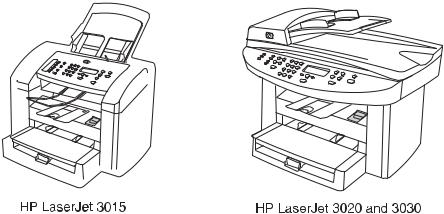
HP LaserJet 3015, 3020, and 3030 all-in-one products
Figure 1-1. HP LaserJet 3015, 3020, and 3030 all-in-one products
●Prints up to 15 pages per minute (less than a 10-second wait for the first page to print)
●150-sheet printer input tray with a 10-page priority input tray
●600 by 600 dpi printing using Resolution Enhancement technology (REt)
●2,000-page print cartridge (using an average of 5 percent toner coverage on printed A4or letter-size pages)
●4 MB of ROM, 32 MB of RAM
●Universal serial bus (USB) port
●1284-B compliant parallel port
●V.34 fax modem that supports speeds up to 33.6 kbps (HP LaserJet 3015 and 3030 only)
●Two RJ-11 ports (one line and one accessory port)
●Two-line LCD display (16 characters per line)
●Additional 2 MB flash ROM for fax storage (up to 110 pages based on a slerexe test page) (HP LaserJet 3015 and 3030 only)
●Expandable input/output (I/O) using the HP Jetdirect 10/100Base-TX
●Individual speed-dial memory and group speed-dial memory (120 entries using the Toolbox) (HP LaserJet 3015 and 3030 only)
2 Chapter 1 Product Information |
ENWW |
|
● |
Supported software |
|
|
|
● |
HP Toolbox |
|
|
● |
HP LaserJet Scan |
|
|
● TWAIN or WIA Scan Driver |
|
|
|
● |
HP LaserJet Fax |
|
|
● Readiris OCR (not installed with other software; separate installation is required) |
|
|
|
● Printer drivers (PCL 5e, PCL 6, and PS |
|
|
|
● |
Installer/unistaller |
|
● |
Supported operating systems |
|
|
|
● Windows 98Se (second edition) |
|
|
|
● Windows Millennium Edition (Me) |
|
|
|
● |
Windows 2000 |
|
|
● Windows XP (32-bit) |
|
|
|
● Mac OS 9.1 or 9.2.x |
|
|
|
● Mac OS X (10.2.x only) |
|
|
Driver-only support for Windows 98 (first edition), Windows XP 64-bit, and Windows 2003 |
||
Note |
|||
|
Server. |
|
|
HP LaserJet 3015 all-in-one product
●Contact image scanner (CIS) 600 ppi, 24-bit color scanner
●30-sheet automatic document feeder (ADF) feeds pages at up to 12 pages per minute (ppm)
●Three status LEDs, a numeric keypad, and menu navigation buttons on the control panel
●Selectable singleor multiple-sheet lever for the ADF
HP LaserJet 3020/3030 all-in-one product
●Coupled charged device (CCD) 600 ppi 24-bit color scanner
●Letter/A4-sized flatbed scanner glass
●50-sheet automatic document feeder (ADF) feeds pages at up to 12 pages per minute (ppm)
●Status LEDs, a numeric keypad, and menu navigation buttons on the control panel (the HP LaserJet 3020 has two status LEDs; the HP LaserJet 3030 has three status LEDs)
Note |
The HP LaserJet 3020 does not have fax capabilities. |
ENWW |
Product configurations 3 |
Product features
The HP LaserJet 3015, 3020, and 3030 all-in-one products are designed to perform the following tasks:
●Print: Print documents with HP LaserJet quality.
●Copy: Make up to 99 laser-quality copies of a 50-page original. It also enlarges, reduces, and lightens/darkens copies. (The HP LaserJet 3020 and 3030 also collate copies.)
●Scan: Scan documents to create electronic text or graphics files.
●Fax: Send and receive documents by using standard fax communications (HP LaserJet 3015 and 3030 only).
4 Chapter 1 Product Information |
ENWW |

Overview of products
Hardware components
Use the following illustrations to identify the hardware components.
Figure 1-2. HP LaserJet 3015 all-in-one hardware components (1 of 2)
Figure 1-2. HP LaserJet 3015 all-in-one hardware components (2 of 2)
1Automatic document feeder (ADF) input tray
2ADF media lever
3Control panel
4ADF output bin
5Print-cartridge-door release
6Output bin
7Priority input slot
8Media input tray
9Parallel port
10USB port
11Fax interface ports
12Power switch
13Power receptacle
ENWW |
Overview of products 5 |

Figure 1-3. HP LaserJet 3020 all-in-one hardware components
1Automatic document feeder (ADF) input tray
2Flatbed scanner lid and ADF output bin
3Control panel
4Print-cartridge-door release
5Output bin
6Priority input tray
7Media input tray
8Parallel port
9USB port
10Power switch
11Power receptacle
Figure 1-4. HP LaserJet 3030 all-in-one hardware components
1Automatic document feeder (ADF) input tray
2Flatbed scanner lid and ADF output bin
3Control panel
4Print-cartridge-door release
5Output bin
6Priority input tray
7Media input tray
8Parallel port
9USB port
10Fax interface ports
11Power switch
12Power receptacle
6 Chapter 1 Product Information |
ENWW |
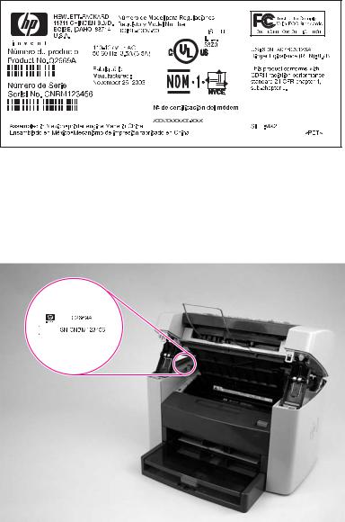
Product identification
Model and serial numbers
An identification label is located on the back of the product. This label contains the model and serial numbers. The serial number contains information about the country/region of origin, revision level, production code, and production number of the product. The label also contains power-rating and regulatory information.
Figure 1-5. |
Sample Identification label (on the back of the product) |
||
|
An additional identification label is located on the top-left side of the scanner support frame. |
||
|
Open the print cartridge door to find this label. |
||
|
The additional serial number label is in the same location on the scanner support frame for all |
||
Note |
|||
|
of the HP LaserJet 3015, 3020, and 3030 all-in-one products. |
||
|
|
|
|
|
|
|
|
Figure 1-6. Location of additional serial number label
ENWW |
Product identification 7 |

Product specifications
Physical specifications
Table 1-1. Physical specifications
Product |
Height |
|
HP LaserJet 3015 |
445 mm |
|
product |
(17.5 inches) |
|
|
||
HP LaserJet |
556 mm |
|
3020/3030 |
21.89 inches) |
|
product |
||
|
Depth |
Width |
Weight |
440 mm |
430 mm |
9.1 kg |
(17.3 inches) |
(16.9 inches) |
(20 pounds) |
483 mm |
497 mm |
11.34 kg |
(19.02 inches) |
(19.6 inches) |
(25 pounds) |
Environmental specifications (all models)
Table 1-2. Environmental specifications (all models)
 Category
Operating environment (unit plugged into an ac outlet)
 Specification
●Temperature: 15° to 32.5° C ( 59° to 90.5° F)
●Humidity: 10 percent to 80 percent relative humidity (no condensation)
Storage environment (unit not plugged into an ac outlet)
●Temperature: -20° to 40° C (-4° to 104° F)
●Humidity: Less than 95 percent relative humidity (with no condensation)
HP LaserJet 3015 performance specifications
Table 1-3. HP LaserJet 3015 performance specifications
Category |
Specification |
Printer capacities and ratings |
|
Print speed |
● 15 pages per minute (ppm) for letter size paper and 14 ppm for |
|
A4-size paper |
|
● First page out in less than 10 seconds |
Media input tray capacity |
150 sheets of regular-weight 60-g/m2 (16-lb) paper or up to 30 |
|
envelopes |
Priority input slot capacity |
10 sheets of regular-weight 75-g/m2 (20-lb) paper or 1 envelope |
Output bin capacity |
Up to 125 sheets of regular-weight 16-lb (60-g/m2) paper |
Minimum paper size |
76 by 127 mm (3 by 5 inches) |
8 Chapter 1 Product Information |
ENWW |

Table 1-3. HP LaserJet 3015 performance specifications (continued)
Category |
Specification |
Maximum paper size |
216 by 356 mm (8.5 by 14 inches). The output bin holds one sheet |
|
of legal-size media 215 by 356 mm (8.5 by 14 inches). Subsequent |
|
sheets of legal-size media slide off of the output bin. |
Media weight |
Media input tray: 60to 163-g/m2 (16to 43-lb) cut sheet paper |
|
Priority input slot: 60to 90-g/m2 (16to 24-lb) single thickness |
|
envelopes |
|
Print paper output: 135to 176-g/m2 (36to 47-lb) postcards |
Base memory |
4 MB of ROM and 32 MB of RAM (9 MB for the product and 23 MB |
|
available to the user) |
Print resolution |
1,200 dpi |
Duty cycle |
● 7,000 single-sided pages per month (maximum) |
|
● 800 single-sided pages per month (average) |
PCL (Printer Control Language) |
Level 5e and 6 |
PostScript® (PS) |
Emulates Adobe® PostScript level 2 |
Copier capacities and ratings |
|
Copy speed |
Up to 15 ppm |
Multiple copies |
Up to 99 per job |
Copy reduction or enlargement |
25 percent to 400 percent |
Acoustic emissions (per ISO |
6.3 Bel sound power level |
9296) while copying |
|
Scanner capacities and ratings |
|
Margins for scanned items |
3.05 mm (0.12 inch) right and left |
|
4.23 mm (0.17 inch) top and bottom |
Scanner duty cycle |
2,000 single-sided items per month |
Scan resolution |
600 dpi color |
Automatic document feeder (ADF) input tray specifications |
|
Input capacity |
Up to 30 sheets of flat 60to 75-g/m2 (16to 20-lb) media |
Media weight (input and output) |
Single sheet setting ( blue media lever set to the right): 42to 260- |
|
g/m2 (11to 69-lb) |
|
Multiple sheet setting ( blue media lever set to the left): 46to 105- |
|
g/m2 (12to 28-lb) |
Media size |
74 by 105 mm (2.9 by 4.1 inches) to 216 mm by 381 mm (8.5 by 15 |
|
inches). The ADF output bin holds one sheet of legal-size media |
|
215 by 356 mm (8.5 by 14 inches). Subsequent sheets of legal-size |
|
media slide off of the ADF output bin. |
Speed |
Up to 12 ppm for letter-size or A4-size media |
Duty cycle |
1,000 pages per month |
Port availability |
|
ENWW |
Product specifications |
9 |

Table 1-3. HP LaserJet 3015 performance specifications (continued)
 Category
USB
Parallel
 Fax capabilities and ratings
Fax transmission speed
Right/left margins for printed pages
Top/bottom margins for printed pages
 Fax compatibility
Fax coding schemes
 Modem speed
Speed dialing
 Distinctive ring detect
Fax resolution (standard)
 Fax resolution (fine)
Fax resolution (superfine)
 Fax resolution (photo) Fax page storage
 Specification
Compatible with USB 2.0 specification
●IEEE 1284-B level 2 device with an IEEE 1284-B receptacle
●Set the host computer to ECP (enhanced capabilities mode)
 3 seconds per page (ITU-T Test Image #1) 6.3 mm (0.25 inch)
5.08 mm (0.2 inch)
 ITU Group 3; ECM
MH, MR, and MMR
 Up to 33,600 bits per second (bps)
Yes
 Yes
Yes
203 by 98 dpi
 203 by 196 dpi
300 by 300 dpi (no halftone)
 300 by 300 dpi (halftone enabled)
Up to 110 slerexe pages
HP LaserJet 3020/3030 performance specifications
Table 1-4. HP LaserJet 3020/3030 performance specifications
Category |
Specification |
Printer capacities and ratings |
|
Print speed |
● 15 pages per minute (ppm) for letter-size paper and 14 ppm for |
|
A4-size paper |
|
● First page out in less than 9 seconds |
Media input tray capacity |
150 sheets of regular-weight 60-g/m2 (16-lb) paper or up to 30 |
|
envelopes |
Priority input tray capacity |
10 sheets of regular-weight 75-g/m2 (20-lb) paper or 1 envelope |
Output bin capacity |
Up to 125 sheets of regular-weight 75-g/m2 (20-lb) paper |
Minimum paper size |
76 by 127 mm (3 by 5 inches) |
Maximum paper size |
216 by 356 mm (8.5 by 14 inches) |
10 Chapter 1 Product Information |
ENWW |

Table 1-4. HP LaserJet 3020/3030 performance specifications (continued)
Category |
Specification |
Media weight |
Media input tray: 60to 163-g/m2 (16to 43-lb) cut sheet paper |
|
Priority input slot: 60to 90-g/m2 (16to 24-lb) single thickness |
|
envelopes |
|
Print paper output: 135to 176-g/m2 (36to 47-lb) postcards |
Base memory |
4 MB of ROM and 32 MB of RAM (9 MB for the product and 23 MB |
|
available to the user) |
Print resolution |
1,200 dpi |
Duty cycle |
● 7,000 single-sided pages per month (maximum) |
|
● 1,000 single-sided pages per month (average) |
PCL (Printer Control Language) |
Level 5e and 6 |
PostScript (PS) |
Emulates Adobe PostScript level 2 |
Copier capacities and ratings |
|
Copy speed |
Up to 15 ppm |
Multiple copies |
Up to 99 per job |
Copy reduction or enlargement |
25 percent to 400 percent |
Acoustic emissions (per ISO |
6.3 Bel sound power level |
9296) while copying |
|
Scanner capacities and ratings |
|
Margins for scanned items |
3.05 mm (0.12 inch) right and left |
|
4.06 mm (0.16 inch) top and bottom |
Media size |
(216 by 356 mm) (8.5 by 11.7 inches) no minimum size |
Scanner duty cycle |
2,000 single-sided items per month |
Scan resolution |
600 dpi color |
Automatic document feeder (ADF) input tray specifications |
|
Input capacity |
Up to 50 sheets of flat 60 to 75-g/m2 (16to 20-lb) media |
Media weight (input and output) |
60to 90-g/m2 (16to 24-lb) |
Media size |
127 by 127 mm (5 by 5 inches) to 216 by 381 mm (8.5 by 15 |
|
inches) |
Speed |
Up to 15 ppm for letter-size or A4-size media |
Duty cycle |
1,000 pages per month |
Port availability |
|
USB |
Compatible with USB 2.0 specification |
Parallel |
● IEEE 1284-B level 2 device with an IEEE 1284-B receptacle |
|
● Set the host computer to ECP (enhanced capabilities mode) |
ENWW |
Product specifications 11 |

Note
Note
Electrical specifications (all models)
The values are subject to change. See http://www.hp.com/support/lj3015 or http://www.hp.com/support/lj3030 for the most current information. The 110-volt and 220-volt power sources are not interchangeable.
Table 1-5. Electrical specifications (all models)
Item |
110-volt models |
220-volt models |
|
Power supply |
110 to 127 V (± 10%) |
220 to 240 V (± 10%) |
|
|
50 to 60 Hz (± 2 Hz) |
50 to 60 Hz (± 2 Hz) |
|
Power consumption (typical) |
300 W (average) |
300 W (average) |
|
Printing |
|||
14 W (average) |
14 W (average) |
||
Standby |
|||
14 W (average) |
14 W (average) |
||
Power Save |
|||
0 W |
0 W |
||
Off |
|||
|
|
||
Minimum recommended circuit |
4.5 A |
2.3 A |
|
capacity |
|
|
Acoustic emissions (all models)
The values are subject to change. See http://www.hp.com/support/lj3015 or http://www.hp.com/support/lj3030 for the most current information. During other operations, acoustic emissions can vary.
Table 1-6. Acoustic emissions (all models)
Activity |
Operator (<1m) |
Bystander (1m) |
Sound power |
level |
|
|
|
Active |
LpAm56 dB (A) |
LpAm48 dB (A) |
LWAd6.1 Bels dB (A) |
Idle |
inaudible |
inaudible |
inaudible |
Skew specifications (all models)
Table 1-7. Skew specifications (all models)
Category |
Specification |
Skew: all vertical lines are parallel to the left edge of the media.
3.0 mm (0.12 inch) over 250 mm (9.85 inches) length (0.8 percent) for cut-sheet media (except for A5 size)
3.3 mm (.13 inch) over 220 mm (8.66 inches) length (1.5 percent) for envelopes, postcards, and A5 size cut-sheet media.
1.65 mm (0.06 inch) over 190 mm (7.48 inches) width for cut-sheet media (leading-edge skew)
12 Chapter 1 Product Information |
ENWW |
Loading...