


 Loading...
DESIGNJET T120/T520 ePrinter Series
Service Manual
© 2012 Hewlett-Packard Development |
Legal notices |
Company, L.P. |
This document contains proprietary |
|
|
1st edition, August 2012 |
information that is protected by copyright. All |
|
rights are reserved. No part of this document |
|
may be photocopied, reproduced, or translated |
|
to another language without the prior written |
|
consent of Hewlett-Packard Company. |

Notices
Warranty |
WARNING |
WARNING |
The information contained in this |
The procedures described in this manual are to |
document is subject to change without |
be performed by HP-qualified service |
notice. |
personnel only. |
Hewlett-Packard makes no warranty of any kind with regard to this material, including, but not limited to, the implied warranties of merchantability and fitness for a particular purpose.
Hewlett-Packard shall not be liable for errors contained herein or for incidental or consequential damages in connection with the furnishing, performance, or use of this material.
Electrical Shock Hazard
Serious shock hazard leading to death or injury may result if you do not take the following precautions:
●Ensure that the AC power outlet (mains) has a protective earth (ground) terminal.
●Disconnect the printer from the power source prior to performing any maintenance.
●Prevent water or any other liquids from running onto electrical components or circuits, or through openings in the enclosure.
Electrostatic Discharge
See the beginning of Chapter 4's Introduction on page 137 of this manual, for precautions you should take to prevent damage to the printer circuits from electrostatic discharge.
Safety Symbols
General definitions of safety symbols are given immediately after the table of contents.
The Warning symbol calls attention to a procedure, practice, or the like, which, if not correctly performed or adhered to, could result in personal injury. Do not proceed beyond a Warning symbol until the indicated conditions are fully understood and met.
CAUTION
The Caution symbol calls attention to an operating procedure, practice, or the like, which, if not correctly performed or adhered to, could result in damage to or destruction of part or all of the printer. Do not proceed beyond a Caution symbol until the indicated conditions are fully understood and met.
Customer Assurance
Customer Experience Section
Large Format Printing Division
Hewlett-Packard Española, S.A.
Avenida Graells, 501
08174 Sant Cugat del Vallès
Spain
ENWW |
iii |
iv |
Notices |
ENWW |

Using this manual
This service manual contains information necessary to test, maintain, and service the following:
HP Designjet T120 Basic Printer 24 inch |
CQ891A |
|
|
HP Designjet T520 Pro Printer 24 inch |
CQ890A |
|
|
HP Designjet T520 Pro Printer 36 inch |
CQ893A |
|
|
For information about using these printers, see the user's guide.
Readership
The procedures described in this service manual are to be performed by HP Certified service personnel only.
Part numbers
Part numbers for printer service parts are located in Parts and diagrams on page 119.
ENWW |
v |
vi |
Using this manual |
ENWW |

Table of contents
1 Printer fundamentals .................................................................................................................................... |
1 |
Overview ................................................................................................................................................................ |
1 |
Using the front panel ............................................................................................................................................. |
1 |
Start-up sequence ................................................................................................................................................. |
3 |
Subsystems ............................................................................................................................................................ |
5 |
2 Troubleshooting .......................................................................................................................................... |
33 |
Printer troubleshooting flowchart ...................................................................................................................... |
34 |
Basic printer troubleshooting ............................................................................................................................. |
35 |
System error codes .............................................................................................................................................. |
38 |
Paper troubleshooting ........................................................................................................................................ |
57 |
Communication troubleshooting ........................................................................................................................ |
62 |
Ink-supplies troubleshooting .............................................................................................................................. |
66 |
Print-quality troubleshooting ............................................................................................................................. |
78 |
Update the firmware ........................................................................................................................................... |
91 |
3 Support menus ............................................................................................................................................ |
95 |
Entering the support menus ............................................................................................................................... |
96 |
Support menu ...................................................................................................................................................... |
98 |
Extended Support menu ................................................................................................................................... |
117 |
4 Parts and diagrams .................................................................................................................................... |
119 |
Introduction ....................................................................................................................................................... |
119 |
Printer support .................................................................................................................................................. |
120 |
Covers ................................................................................................................................................................ |
121 |
Roll covers ......................................................................................................................................................... |
122 |
Right-hand assemblies ..................................................................................................................................... |
123 |
Left-hand assemblies ........................................................................................................................................ |
125 |
Carriage assembly ............................................................................................................................................. |
127 |
Paper path (front) .............................................................................................................................................. |
129 |
Paper path (rear) ............................................................................................................................................... |
130 |
Roll supports ..................................................................................................................................................... |
131 |
Sensor Kit ........................................................................................................................................................... |
132 |
Miscellaneous parts ........................................................................................................................................... |
133 |
ENWW |
vii |
5 Removal and installation ........................................................................................................................... |
135 |
Introduction ....................................................................................................................................................... |
137 |
Customer Self Repair parts ............................................................................................................................... |
139 |
Videos available ................................................................................................................................................. |
140 |
Recommended checks after replacing parts .................................................................................................... |
140 |
Top Cover ........................................................................................................................................................... |
141 |
Front Cover ........................................................................................................................................................ |
144 |
Right Cover ........................................................................................................................................................ |
147 |
Ink Cartridge Cover ............................................................................................................................................ |
150 |
Left Cover .......................................................................................................................................................... |
152 |
Roll Cover ........................................................................................................................................................... |
154 |
Back Cover ......................................................................................................................................................... |
157 |
Front Panel ........................................................................................................................................................ |
159 |
Front Panel Cable .............................................................................................................................................. |
165 |
Central Cover ..................................................................................................................................................... |
166 |
Upper-Roll Paper Guide ..................................................................................................................................... |
171 |
Left Roll Support ............................................................................................................................................... |
174 |
Right Roll Support ............................................................................................................................................. |
179 |
Top Cover Sensor ............................................................................................................................................... |
182 |
Top Cover Sensor Cable ..................................................................................................................................... |
185 |
Encoder Strip ..................................................................................................................................................... |
187 |
Ink Cartridge Cover PCA Assembly .................................................................................................................... |
192 |
Power Supply ..................................................................................................................................................... |
196 |
Main PCA ............................................................................................................................................................ |
198 |
Paper Motor ....................................................................................................................................................... |
204 |
Encoder PCA and Index ...................................................................................................................................... |
206 |
Encoder Disk ...................................................................................................................................................... |
210 |
Trailing Cable ..................................................................................................................................................... |
213 |
Service Station ................................................................................................................................................... |
220 |
Prime Pump ....................................................................................................................................................... |
226 |
Carriage and Belt ............................................................................................................................................... |
229 |
Carriage Belt ...................................................................................................................................................... |
235 |
Right Gear Train Module .................................................................................................................................... |
237 |
Starwheel Assembly .......................................................................................................................................... |
239 |
Output Shaft ...................................................................................................................................................... |
241 |
Output Tray ........................................................................................................................................................ |
249 |
Multi-Sheet Tray Assembly ............................................................................................................................... |
252 |
Multi-Sheet Tray Assembly Extensions ............................................................................................................ |
253 |
Output Platen .................................................................................................................................................... |
255 |
Carriage Motor ................................................................................................................................................... |
260 |
Cutter Assembly ................................................................................................................................................ |
264 |
Cutter Guide ....................................................................................................................................................... |
271 |
Out-Of-Paper Sensor ......................................................................................................................................... |
273 |
Out-Of-Paper Sensor Cable ............................................................................................................................... |
276 |
viii |
ENWW |
Output Tray Sensor Assembly ........................................................................................................................... |
278 |
Output Tray Extender Sensor Cable .................................................................................................................. |
281 |
Carriage Line Sensor .......................................................................................................................................... |
284 |
Bundle Board ..................................................................................................................................................... |
288 |
Bundle Board FFC cable ..................................................................................................................................... |
290 |
Pinchwheels ....................................................................................................................................................... |
295 |
Left Spittoon ...................................................................................................................................................... |
301 |
6 Preventive maintenance ............................................................................................................................ |
305 |
Preventive maintenance ................................................................................................................................... |
306 |
Preventive maintenance kits ............................................................................................................................ |
312 |
7 Appendices ................................................................................................................................................ |
315 |
Important links .................................................................................................................................................. |
316 |
Front-panel home screen and menu map ........................................................................................................ |
317 |
Support menu tree ............................................................................................................................................ |
327 |
Extended Support menu tree ............................................................................................................................ |
328 |
How to check whether your computer is connected to your network ............................................................. |
329 |
Wireless troubleshooting report error cases .................................................................................................... |
332 |
CSR fliers ............................................................................................................................................................ |
341 |
ENWW |
ix |
x |
ENWW |
1 Printer fundamentals
●Overview
●Using the front panel
●Start-up sequence
●Subsystems
Overview
Feature |
HP Designjet T120 |
HP Designjet T520 |
More information |
|
|
|
|
Paper source |
Roll and multi-sheet tray |
See the user's guide |
|
|
|
|
|
Hardware differences |
Stand as an accessory, no roll |
Stand in box, roll cover |
|
|
cover |
|
|
|
|
|
|
Connectivity |
Wi-Fi, Fast Ethernet LAN, USB |
Important! LAN and Wi-Fi are |
|
|
|
|
not compatible |
|
|
|
|
Web Services |
Automatic firmware upgrade |
The printer needs to be |
|
|
|
|
Internet-connected: Web |
|
HP Designjet ePrint & Share |
Services do not work with a |
|
|
Printing by email |
USB connection. For some |
|
|
configurations, the latest |
||
|
|
|
firmware release is needed. |
|
|
|
Manual firmware upgrade is |
|
|
|
available in both printers via |
|
|
|
HP Designjet Utility (Windows) |
|
|
|
or HP Utility (Mac OS). The |
|
|
|
same firmware file is used for |
|
|
|
T120 and T520. |
|
|
|
|
Speed |
70 s per page on A1/D |
35 s per page on A1/D |
|
|
|
|
|
Resolution |
Up to 1200 × 1200 dpi |
Up to 1200 × 2400 dpi |
|
|
|
|
|
Memory and languages |
256 MB, HP-PCL3 (processing |
1 GB, HP-GL/2 (processing in |
|
|
in printer) |
computer) |
|
|
|
|
|
Supplies |
HP 711 29 ml Cyan, Magenta, Yellow |
Ink cartridges and printhead |
|
|
|
|
can be replaced by the |
|
HP 711 38 ml and 80 ml Black |
customer. |
|
|
|
|
|
|
One on-axis printhead for all colors |
|
|
|
|
|
|
Using the front panel
The front panel is a touch-sensitive screen with a graphical user interface; it is located on the front left of the printer. It gives you complete control of your printer: from the front panel, you can print, view information
ENWW |
Overview 1 |

about the printer, change printer settings, perform calibrations and tests, and so on. The front panel also displays alerts (warning and error messages) when needed.
The front panel has a large central area to display dynamic information and icons. On the left and right sides you can see up to six fixed icons at different times. Normally they are not all displayed at the same time.
To the right of the front panel is the Power key, with which you can turn the printer on or off. The key is illuminated when the printer is on. It flashes when the printer is in transition between on and off.
Left and right fixed icons
●shows the status of the wireless connection: if the blue light is shining, the wireless connection is active.
●Press to return to the home screen.
●Press to view help about the current screen.
●Press to go to the previous item.
●Press to go to the next item.
●Press to go back to the previous screen.
●Press to cancel the current process.
Home screen dynamic icons
The following items are displayed only on the home screen.
●At the top left of the home screen is a message telling you which paper source is active.
●Press to view Web Services status and display your printer’s email address.
●Press to view connectivity status information and to perform network configuration. If a network cable is connected, is displayed instead.
 NOTE: It is not possible to use wireless and wired network connections simultaneously.
●Press to view ink information.
●Press to change printer settings.
●Press to load, unload, and change options for roll paper.
●Press to change options for the multi-sheet tray, or to activate it.
●Press to load, unload, and change options for single sheets.
●Press to access HP Designjet ePrint & Share.
 NOTE: The active paper source is indicated by a slightly larger icon, with a white tick in a green circle: .
2 Chapter 1 Printer fundamentals |
ENWW |

If the printer is left idle for some time, it goes into sleep mode and switches off the front-panel display. To change the time that elapses before sleep mode, press , then Printer preferences > Sleep. You can set a time between 5 and 240 minutes.
The printer wakes from sleep mode and switches on the front-panel display whenever there is some external interaction with it.
The following table shows an overview of the two types of support menu available, for more details see Entering the support menus on page 96.
 NOTE: The icons mentioned in this table will not be visible in the front panel: you must press the front panel in the places where they normally appear, as shown in the front panel illustration at the start of this section.
Label |
Description |
|
|
Support menu: This can be used by customers under the |
From the Home screen, press the following icons one after the |
guidance of phone call agents assisting remotely. Using this |
other: , ,, . |
menu, customers can perform troubleshooting tasks and access |
|
printer information. |
If there is a system error, you may not be able to reach the home |
|
screen. In this case, press the Power button and hold it down for |
|
15 seconds. |
|
|
Extended Support menu: Service engineers only |
From the Home screen, press the following icons one after the |
|
other: , , , . |
|
|
Start-up sequence
There are three states between power-on and the Home screen:
1.Electronics initialization
2.Firmware initialization
3.Mechanical initialization
State 1: Electronics initialization
1.The front panel moves from flashing white light to turning dark.
2.The printer reads the firmware.
 NOTE: At this stage, if something is broken, it will not be possible to enter the Support menu. To diagnose what is happening, go to the front panel blank troubleshooting. (and add here the link). Subsequently, you can enter the Support menu to troubleshoot if necessary.
State 2: Firmware initialization
1.The HP logo appears with a static bar.
2.Bundle board and ASICs are initialized.
ENWW |
Start-up sequence 3 |
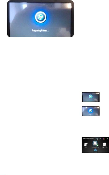
3.The HP logo changes.
State 3: Mechanical initialization
1.A basic check of servos
2.A check that the Scan Axis and Paper Axis are unobstructed by scraps of paper or other items
3.Paper and print system initialization
Initialization flow summary
Time (sec) |
Printer state |
Visual and acoustic information |
|
|
|
0 |
Power on |
Using the Power button |
|
|
|
10 |
Electronics initialization |
|
|
|
|
27 |
Mechanical initialization |
|
|
|
|
|
1. Basic check of servos |
Sound of the printer's motors |
|
|
|
|
2. Scan Axis, Paper Axis check |
Carriage movement |
|
|
|
|
3. Paper and print system initialization |
Paper movement |
|
|
|
45 |
Ready state |
|
|
|
|
|
|
|
 NOTE: Initialization lasts around 45 s if there was a clean power-off (using the front panel Power button). If there was a dirty power-off, the printer will require more time to inititialize (to ensure that the printhead is in a good state).
4 Chapter 1 Printer fundamentals |
ENWW |
Subsystems
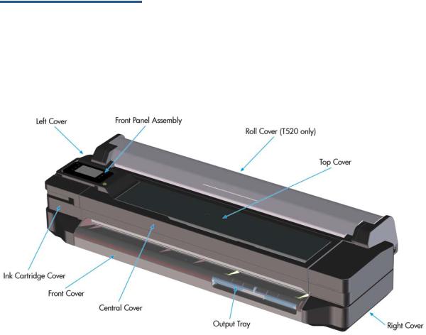
Covers
Functionality
These parts cover the printing mechanism and act as protection from potential knocks or dust. They also prevent the customer from coming into contact with unsafe parts during the operation of the printer. Finally, the covers complement the style and aesthetics of the printer.
The T120 and T520 printers have covers of different colors, and a different configuration of the roll cover, as seen in the following table:
|
HP Designjet T120 |
HP Designjet T520 |
|
|
|
Roll Cover |
Not Present |
Transparent |
|
|
|
Top Cover |
Opaque Black |
Transparent |
|
|
|
Output Platen |
Black-Blackberry |
Black-Olive |
|
|
|
Output Tray |
Black-Olive |
Black-Olive |
|
|
|
Components
Other than the cosmetic aspects of the covers, there are several sensors related to the subsystem covers. The sensors are designed to detect the status of the cover, open or closed.
ENWW |
Subsystems 5 |

●The Ink Cartridge Cover Sensor senses whether the Ink Cartridge Cover is open or closed. Opening the Ink Cartridge Cover starts ink cartridge replacement automatically. The sensor is hosted in the printer chassis.
●The Central Cover hosts the Top Cover Sensor to sense whether the Top Cover is open or closed.
 IMPORTANT: Be careful to avoid damaging the sensor while removing the Central Cover. See Central Cover on page 166.
●The Output Tray Sensor senses whether the Output Tray is open or closed. To avoid paper jams while printing on roll paper, the tray should be closed.
 IMPORTANT: Damage to the covers can cause the sensors to malfunction.
Removal and installation
In order to proceed with the removal and installation of the covers its important to bear in mind their cosmetic aspects, some surfaces of the covers have a glossy finish, which requires maximum attention as they are very delicate and susceptible to scratches and finger marks. It is recommended that you use gloves for any service operation involving the covers.
Due to the layout of the covers, it is important to bear in mind that some parts require removal before you can remove a specific cover.
●Right Cover requires Front Cover removal.
●Left Cover requires Front and Ink Cartridge Cover removal.
●Roll Cover requires Right and Left Cover removal.
●Top Cover requires Front Panel assembly removal.
●Central Cover requires Right Cover and Left Cover removal.
Related tests
Sensor tests for the Top Cover, Ink Cartridge Cover, and Output Tray operation. See Diagnostics menu on page 100.
Electronics
Other than the sensor boards, there are no electronics related to this subsystem.
Printhead health systems: Service Station, Primer system, and Left Spittoon
Functionality
The service station is responsible for printhead maintenance. It takes action to clean ink residues and service ink nozzles, and prevents ink from drying in critical zones by capping the printhead once printing has finished.
The Primer system provides the necessary air pressure to the printhead to perform initialization. This system also provides pressure to the necessary printhead service operations (by boosting air which pushes ink out through the printhead nozzles, cleaning residues of dried ink and other particles).
The Left spittoon is a small container located to the left of the print-zone area, this is the area used by the printhead to “spit” a small amount of ink at the end/beginning of the printing swath in order to ensure correct nozzle heath for left-to-right printing.
6 Chapter 1 Printer fundamentals |
ENWW |
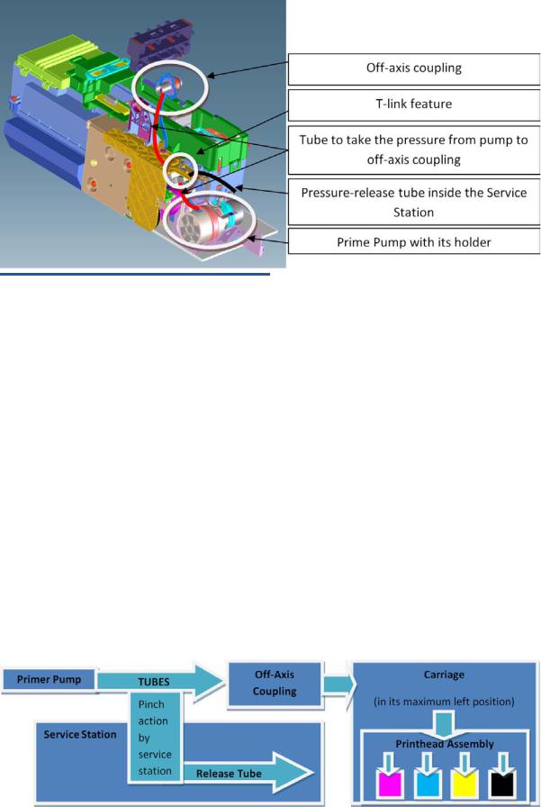
Components
Item |
Function |
|
|
Off-axis coupling assembly |
This is a rubber spring link located on the side plate of the scan |
|
axis (area where the Carriage moves). It links the primer system |
|
with the Carriage when the Carriage is located in its maximum left |
|
position. This system ensures the pressure from the primer |
|
reaches the printhead for nozzle servicing. |
|
|
Prime Pump |
This is an air pump which provides the necessary pressure for |
|
printhead servicing and nozzle repair. The Prime Pump is |
|
suspended on a rubber holder to minimize the noise that the |
|
Prime Pump makes while in operation. |
|
|
Primer Tubes |
The tubes take the air from the Prime Pump to the off-axis |
|
coupling. There is a T link feature connected to a tube that goes |
|
inside the service station; the purpose of this tube is to release |
|
the air pressure from the system. The tube is pinched by the |
|
shuttle of the service station when reaching a certain position; |
|
this action closes the circuit and allows the system to be |
|
pressurized. With the movement of the service station the tube is |
|
released, allowing the pressure from the system to escape. |
|
|
Notes and considerations
Any leakage in the primer system will generate poor or no priming, this will affect nozzle heath (or even cause the printhead startup to fail). Bear in mind that the system is not just for the Prime Pump and tubes, the prime pressure is transmitted via the off-axis coupling to the Carriage and from there to the printhead assembly and from there to the cartridges.
ENWW |
Subsystems 7 |
 NOTE: There is no pressure sensor in the system. The Prime Pump operates at a certain time to reach a specific pressure level, the system is depressurized by releasing the pinching of the release tube in the Service Station (by moving the service station).
NOTE: It is important to ensure the Carriage reaches the maximum left position; if not, the off-axis coupling will not connect the Prime Pump with the Carriage. Also, the coupling is made of a rubbery material, degradation of the material will affect Primer performance due to air leaks.
Electronics
The control driver of the Prime Pump is located on the remote controller board located on the right-hand side of the printer. There is no encoder for the Prime Pump. This pump is managed only by a DC motor activated for a certain period of time to create the required priming pressure.
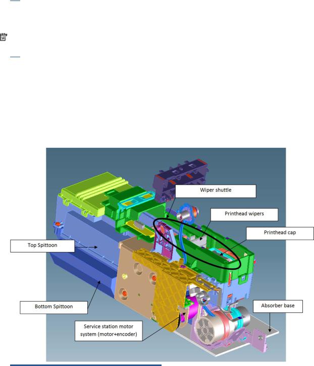
Service Station system
Functionality
Item |
Function |
|
|
Printhead Wipers |
These are rubber paddles that are passed through the nozzle |
|
plate of the printhead with the Service Station movement. They |
|
clean the excess ink from the nozzle plate with a rubbing action. |
|
|
Printhead Cap |
This caps and protects the nozzles from drying when they are not |
|
printing. |
|
|
Service Station Motor system |
This moves the shuttle with the wiper and the cap so that these |
|
two items can perform their functions. The system is composed |
|
of a DC motor and an encoder disk with an encoder sensor to read |
|
the motor position. |
|
|
8 Chapter 1 Printer fundamentals |
ENWW |

Item |
Function |
|
|
Bottom Spittoon |
This part acts as an ink reservoir when spitting and nozzle health |
|
operations are performed. It contains diapers that prevent the ink |
|
becoming liquid. |
|
|
Top Spittoon |
This seals the reservoir and completes the main body of the |
|
service station. |
|
|
Absorber Base |
This is made of foam and is located under the service station on |
|
top of the printer structure. It works as an additional diaper in |
|
case ink spills out of the Service Station. |
|
|
Wiper Shuttle |
This mobile part is propelled by the motor that contains the Wiper |
|
and Cap. Depending on the position, spitting, wiping, capping, or |
|
priming can take place: |
|
Spitting: The printhead “spits” a little ink into the spittoon to get |
|
the nozzles conditioned and ready for the next swath of printing. |
|
Wiping: A physical action to pass the rubber wipers through the |
|
printhead nozzles. |
|
Capping: Parking the printhead to maintain nozzle heath during |
|
printer inactivity, with a surrounding seal. |
|
Priming: Squirts ink through the nozzles to clean and unblock |
|
them. |
|
|
Notes and considerations
The service station is offered as a complete service part for full replacement. The failures from this subsystem are usually related to the mobile parts: motor or encoder failures that prevent the shuttle from reaching the positions for capping or uncapping.
With the life primer system, tube pinching can present an issue (although it is designed to function for the life of the printer).
When the Service Station is replaced, it is mandatory to reset the Preventive Maintenance Kit for the Service Station, this will trigger a simple calibration that is done with the Service Station on the next printer startup. The calibration measures the length of the Service Station (shuttle front bump to shuttle rear bump), which ensures a correct capping position.
Electronics
All the controlled movements for the Service Station are done from the remote-controlled board located on the right-hand side of the printer. Issues with the Service Station can also be related to this control board.
Paper path and Cutter
Functionality
The paper path
This comprises all the elements of the printer in contact with the paper, designed to hold, move, and manage it in a controlled manner in order to print.
Paper can be loaded using a roll, which is mounted on the rear spindle, or single sheets loaded from the Multi-Sheet Tray, or single sheets loaded singly.
The paper passes from its source (Roll, Single Tray, or Multi-Sheet Tray) until it touches the Out-Of-Paper Sensor, when the printer detects the presence of the paper and proceeds to load it.
ENWW |
Subsystems 9 |
To perform the paper feed, the printer catches the paper in between the Drive Roller and the Pinch Rollers (Pinch Rollers are spring-loaded pushing the paper down on top of the Drive Roller), then the paper is pushed forwards on top of the Print Platen in the print zone, which is where the printing operation is performed. The paper advance is provided by a motor that moves the Drive Roller. The exact position of the Drive Roller and hence the paper is controlled by an Encoder Disk located on the roller axis.
The printed paper then passes between the Output Shaft and the Starwheels (which keep the paper tension as flat as possible for printing) to exit on the Output Platen, where it is held in case of cut sheet or is cut to fall on the output basket in the case of roll paper.
The Output Shaft is designed to over-advance the Drive Roller movement slightly, and hence create the necessary paper tension to keep the paper as flat as possible. The Starwheels are spring-loaded and are designed to create force on top of the paper, this is done so as to leave the paper unmarked and at the same time allow the Output Shaft force to be appropriately transmitted.
In the Roll configuration, the rewinder module generates back force while printing to facilitate paper control.
A key electrical element of the paper path is the Paper Sensor (also known as the Out-Of-Paper Sensor or OOPS). This sensor is located at the beginning of the Print Platen; it detects paper insertion for roll load and single-sheet load.
Electronics
In the paper-path driving system, the only electrically active element is the Drive Roller. The Drive Roller is impelled by the drive roller motor and it contains an Encoder Disk on the axis to determine its position. The Encoder Disk is read by two sensors. One, the “encoder sensor”, designed to read the encoder, counts the Encoder Disk (the Encoder Disk outer marks) and another one, the “encoder index sensor”, determines the start position (the 0 position) of the Drive Roller by reading the inner thicker lines of the Encoder Disk.
 NOTE: Every time the printer starts up, it searches for the 0 position of the Drive Roller. If this search fails (which means that the index sensor is faulty), the printer will give a system error and will be unable to initialize.
The roll paper input system
Functionality
This system keeps the roll in place and ensures controlled rotation.
It contains the rewinder, which rewinds the paper for paper ejection, and provides an opposite tension to the paper advance for better paper control.
10 Chapter 1 Printer fundamentals |
ENWW |
●The Left Support encloses the Rewinder Motor and Encoder, containing a set of gears that transmit the Rewinder motion to the spindle. There is a V-shaped spring to load and fix the spindle in position.
●The Right Support holds the spindle in position to rotate over passive rollers.
In the T520, the right support also contains the dampers for the roll cover opening movement control (the internal dampers perform a braking action preventing sudden movement during the opening operation).
 NOTE: The right support for the T120 models does not contain dampers. The T120 and T520 have two different assemblies from the factory, nevertheless both can be replaced by the damper option of T520 (identical from the external point of view), and there is only one service part available.
●The spindle is designed to hold the paper rolls, and receive the motion from the rewinder gear in the Left Support. It consists of a central bar and two hubs; the right hub is fixed to determine the right-side loading position of the paper, and the moveable left hub adjusts to the width of the paper.
●The Roll Cover (T520 only) shields the roll from dust.
 NOTE: The Roll Cover is a passive part, with no sensor: the printer does not know its status.
Electronics
The Rewinder Motor and Encoder system are directly controlled by the Main PCA.
The paper output system
Functionality
The system ensures that the printed paper follows a controlled path and acquires a certain shape in order to be delivered properly to the user. It also has a cosmetic function.
The system includes a set of three telescopic trays, which are extended to collect the cut-sheet paper printed from the Multi-Sheet Tray.
ENWW |
Subsystems 11 |
There are two roll-paper control tabs that are deployed automatically when the telescopic trays of the Output Tray are in the closed position. This is a purely mechanical action as the tabs are pushed up by the output trays when closed. The purpose of those tabs is to control the shape of the roll paper when coming out of the paper path.
The Front Cover is located underneath the Output Platen.
Electronics
The only electronic component related to the Output Platen is the Output Tray Sensor located underneath the output trays. The sensor is activated when the three output trays are fully closed. The sensor cable is routed via the front of the machine and is directly connected to the main PCA.
The Cutter system
The Cutter cuts the paper after the print has completed.
It comprises 1) a cutter module that cuts the paper with two rotary blades, 2) a Cutter Bridge attached to the Carriage that catches and releases the Cutter to perform the cutting operation and then to leave it in capping position, 3) a Cutter Guide that holds the movement of the Cutter along the printer width.
In order to operate the Cutter, it needs to be in the parked position. If not, the Cutter will not be engaged by the Cutter Bridge and the printer will not perform the cutting action.
12 Chapter 1 Printer fundamentals |
ENWW |
Whenever the printer initializes, it performs a parking movement with the Carriage to ensure that the Cutter is left in the appropriate position.
The printer does not have any feedback about the cutter engagement action. Hence, if for any reason the engagement is not performed correctly, the printer will continue operating as if the engagement has occurred.
How activation works
1.Pre-activation phase: The Cutter Engagement Feature of the Bridge gets into the funnel of the Cutter Module grooving the Cutter to ensure the correct position for activation.
2.Hook catching: The cutter bridge continues moving to the left pushing down the cutter hook (in orange), after the left side of the cutter bridge passes the Carriage stops and the cutter hook returns to its position due to its spring motion.
ENWW |
Subsystems 13 |
3.Cutter action: The left feature of the cutter bridge pushes the cutter to the left, performing the cutting operation.
How deactivation works
1.Disengagement: Hook Bridge changes direction moving now from right to the left, so that Cutter Hook slides out of the Cutter Catch Feature.
14 Chapter 1 Printer fundamentals |
ENWW |
2.Move-away action: the Cutter Hook deactivates from the bridge by passing in front of it.
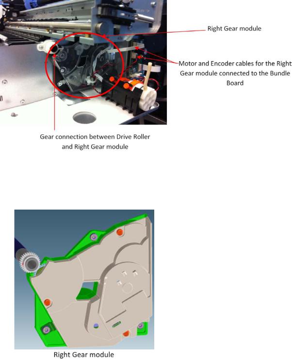
Accessory tray and right gear module
Functionality
The accessory tray holds and loads the cut-sheet paper for the printer. The accessory tray itself is a completely mechanical system with no electronics or motors. All the motion drives for both picking and paper drive are or created or transmitted by the Right Gear module located on the right-hand side of the printer, behind the Service Station.
The Right Gear module has two main functions. It contains the motor encoder and gear drive system for the picking mechanism, and it contains the gear train system to transmit the movement from the drive roller to the accessory tray.
ENWW |
Subsystems 15 |
Right Gear module functionality
The Right Gear module has two different functions associated with the Multi-Sheet Tray.
1.The paper drive from the Multi-Sheet Tray into the platen area (until the cut sheet reaches the drive roller area).
16 Chapter 1 Printer fundamentals |
ENWW |
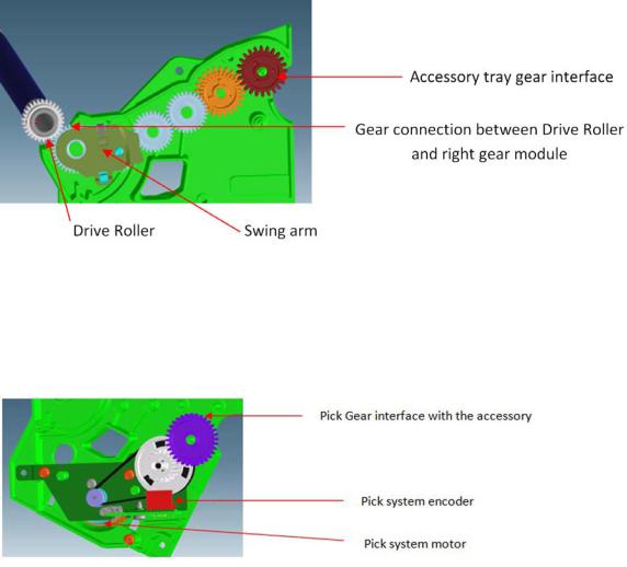
The intermediate shaft in the Multi-Sheet Tray is driven by the drive roller through a gear train inside the Right Gear module. The intermediate shaft meshes with the Multi-Sheet Tray gear interface (red gear in the picture) at the end of the train. A swing arm engages the gear train when the Drive Roller is driven backwards (as shown in the picture), driving the intermediate shaft forwards. When the Drive Roller is driven forwards, the swing arm disengages from the gear train and the intermediate shaft is not driven. This action is to prevent reverse paper movement to be transmitted to the Multi-Sheet Tray.
2.Picking functionality drive system
The Multi-Sheet Tray pick drive assembly is mounted in the right side gear module. The assembly contains a DC motor and pinion, belt, cluster pulley, and gear. An encoder (not shown, but it is located in front of the white gear shown in the picture) is read by the encoder sensor (in red in the picture) to servo-control the pick drive.
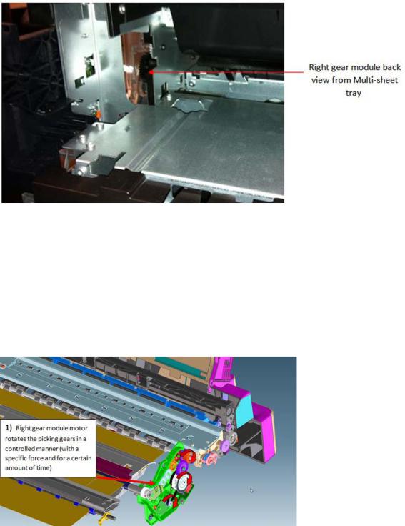
Right Gear and Multi-Sheet Tray interface
The two gears from the Right Gear module interface with the Multi-Sheet Tray by location once the MultiSheet Tray is locked in position; both gears can be considered fully engaged.
ENWW |
Subsystems 17 |
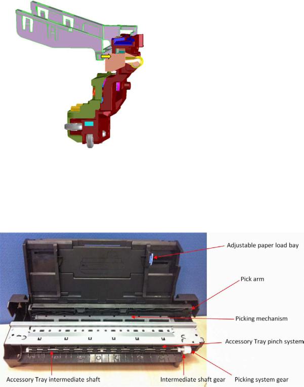
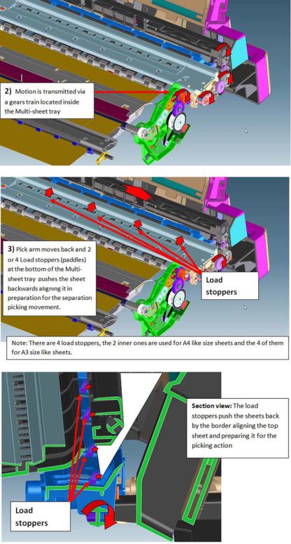
Multi-Sheet Tray functionality
The function of the Multi-Sheet Tray is to pick and feed the cut-sheet paper until the paper is grabbed by the drive roller (drive roller and pinch system).
The actions performed for those operations are (1) sheet pick and (2) sheet input.
1. Sheet pick
This movement is transmitted through a lateral gear chain in the Multi-Sheet Tray towards the swing arm, which is pushed towards the paper, and the picking mechanism located at the bottom of the Multi-Sheet Tray, which separates the top sheet from the stack of pages.
18 Chapter 1 Printer fundamentals |
ENWW |
ENWW |
Subsystems 19 |

2. Sheet input
Once the paper is in the intermediate shaft area, the drive roller is rotated, impelling the intermediate shaft through the right gear module, pushing the sheet towards the inside of the printer, so that it will be grabbed by the drive roller and main printer pinch system, proceeding with the standard paper drive motion (as with roll paper).
20 Chapter 1 Printer fundamentals |
ENWW |
Loading...