


VOYAGER 1250G

™
Voyager
TM
1250g
Single-Line Laser Scanner
User’s Guide

Disclaimer
Honeywell International Inc. (“HII”) reserves the right to make changes in speci-
fications and other information contained in this document without prior notice,
and the reader should in all cases consult HII to determine whether any such
changes have been made. The information in this publication does not repre-
sent a commitment on the part of HII.
HII shall not be liable for technical or editorial errors or omissions contained
herein; nor for incidental or consequential damages resulting from the furnish-
ing, performance, or use of this material.
This document contains proprietary information that is protected by copyright.
All rights are reserved. No part of this document may be photocopied, repro-
duced, or translated into another language without the prior written consent of
HII.
© 2011 Honeywell International Inc. All rights reserved.
Other product names or marks mentioned in this document may be trademarks
or registered trademarks of other companies and are the property of their
respective owners.
Web Address:
www.honeywellaidc.com

1
Chapter 1 - Getting Started
About This Manual ......................................................1-1
Unpacking Your Device............................................... 1-1
Connecting the Device ................................................ 1-1
Connecting with USB ............................................ 1-1
Connecting with Keyboard Wedge........................ 1-2
Connecting with RS232 Serial Port....................... 1-3
Connecting with RS485......................................... 1-4
Reading Techniques ................................................... 1-5
Menu Bar Code Security Settings ............................... 1-5
Setting Custom Defaults ............................................. 1-5
Resetting the Custom Defaults ................................... 1-6
Resetting the Factory Defaults.................................... 1-7
Chapter 2 - Programming the Interface
Introduction ................................................................. 2-1
Programming the Interface - Plug and Play ................ 2-1
Keyboard Wedge................................................... 2-1
IBM PS2 Keyboard................................................ 2-1
RS232 Serial Port.................................................. 2-1
RS485 ................................................................... 2-2
OPOS Mode.......................................................... 2-3
USB IBM SurePos................................................. 2-4
IBM Secondary Interface....................................... 2-4
USB PC or Macintosh Keyboard........................... 2-5
USB HID................................................................ 2-5
HID Fallback Mode................................................ 2-5
USB Serial Commands ............................................... 2-6
USB Serial Emulation............................................ 2-6
CTS/RTS Emulation.............................................. 2-6
ACK/NAK Mode..................................................... 2-7
Communication Timeout ....................................... 2-7
NAK Retries........................................................... 2-8
Support BEL/CAN in ACK/NAK............................. 2-8
Table of Contents

2
Verifone
®
Ruby Terminal Default Settings ..................2-9
Gilbarco
®
Terminal Default Settings............................2-9
Honeywell Bioptic Aux Port Configuration .................2-10
Datalogic™ Magellan
©
Bioptic
Aux Port Configuration ............................................2-10
NCR Bioptic Aux Port Configuration..........................2-10
Wincor Nixdorf Terminal Default Settings..................2-11
Wincor Nixdorf Beetle™ Terminal Default Settings...2-11
Keyboard Country Layout..........................................2-12
Keyboard Wedge Modifiers .......................................2-14
ALT Mode ............................................................2-14
Keyboard Style ....................................................2-14
Keyboard Conversion ..........................................2-15
Keyboard Modifiers..............................................2-16
Inter-Scan Code Delay ........................................2-17
<F0> Break Character .........................................2-18
Keyboard Wedge Defaults...................................2-18
RS232 Modifiers ........................................................2-19
RS232 Baud Rate................................................2-19
RS232 Word Length: Data Bits, Stop Bits,
and Parity ....................................................... 2-20
RS232 Handshaking............................................2-21
RS232 Timeout....................................................2-22
XON/XOFF ..........................................................2-22
ACK/NAK .............................................................2-23
Communication Timeout......................................2-23
NAK Retries .........................................................2-24
Support BEL/CAN in ACK/NAK ...........................2-25
RS232 Defaults.................................................... 2-25
NCR Modifiers ...........................................................2-25
NCR ACK/NAK ....................................................2-25
Block Check Character ........................................2-26
NCR Prefix...........................................................2-26
NCR Suffix ...........................................................2-26
NCR Prefix/Suffix.................................................2-27
NCR NOF (Not-on-File) Error ..............................2-27
Scanner to Bioptic Communication............................2-27

3
Scanner-Bioptic Packet Mode............................. 2-28
ACK/NAK............................................................. 2-28
Communication Timeout ..................................... 2-28
Chapter 3 - Input/Output Settings
Power Up Beeper........................................................ 3-1
Beep on BEL Character ..............................................3-1
Good Read and Error Indicators ................................. 3-2
Beeper – Good Read ............................................ 3-2
Beeper Volume – Good Read ............................... 3-2
Beeper Pitch – Good Read ................................... 3-3
Beeper - Transmit Order ....................................... 3-3
Beeper Pitch – Error.............................................. 3-3
Beeper Duration – Good Read.............................. 3-4
Number of Beeps – Good Read............................ 3-4
Number of Beeps – Error ...................................... 3-4
LED Indicators............................................................. 3-6
LED Settings ......................................................... 3-6
LED Brightness ..................................................... 3-7
In-Stand and Out-Of-Stand Settings ...........................3-7
In-Stand and Out-of-Stand Defaults...................... 3-8
Presentation Modes .............................................. 3-8
Manual Activation Mode........................................ 3-9
End Manual Activation After Good Read............... 3-9
Manual Activation Laser Timeout -
Button Settings............................................... 3-10
CodeGate
®
.......................................................... 3-11
Object Detection Mode........................................ 3-11
End Object Detection After Good Read .............. 3-12
Object Detection Laser Timeout.......................... 3-12
Object Detection Distance................................... 3-13
Character Activation Mode........................................ 3-13
Activation Character............................................ 3-13
End Character Activation After Good Read......... 3-14
Character Activation Laser Timeout.................... 3-14
Character Deactivation Mode.................................... 3-15

4
Deactivation Character ........................................3-15
Reread Delay.............................................................3-16
User-Specified Reread Delay ....................................3-16
Output Sequence Overview.......................................3-16
Require Output Sequence ...................................3-16
Output Sequence Editor ......................................3-17
To Add an Output Sequence ...............................3-17
Other Programming Selections............................ 3-17
Output Sequence Editor ......................................3-19
Sequence Timeout............................................... 3-19
Sequence Match Beeper .....................................3-20
Partial Sequence .................................................3-20
Require Output Sequence ...................................3-20
No Read.....................................................................3-21
Chapter 4 - Data Editing
Prefix/Suffix Overview..................................................4-1
To Add a Prefix or Suffix:.......................................4-1
To Clear One or All Prefixes or Suffixes ................4-2
To Add a Carriage Return Suffix to
All Symbologies................................................4-3
Prefix Selections..........................................................4-3
Suffix Selections ..........................................................4-4
Transmit Alternate Extended ASCII Characters ..........4-4
Function Code Transmit ..............................................4-6
Communication Check Character................................4-6
Intercharacter, Interfunction, and
Intermessage Delays.................................................4-7
Intercharacter Delay ..............................................4-7
User Specified Intercharacter Delay ......................4-7
Interfunction Delay.................................................4-8
Intermessage Delay...............................................4-9
Chapter 5 - Data Formatting
Data Format Editor Introduction...................................5-1
To Add a Data Format .................................................5-1

5
Other Programming Selections ............................. 5-3
Terminal ID Table........................................................ 5-4
Data Format Editor Commands .................................. 5-4
Move Commands .................................................. 5-5
Search Commands................................................ 5-6
Miscellaneous Commands .................................... 5-7
Data Formatter ............................................................ 5-8
Data Format Non-Match Error Tone...................... 5-9
Primary/Alternate Data Formats................................ 5-10
Single Scan Data Format Change....................... 5-10
Chapter 6 - Symbologies
All Symbologies........................................................... 6-1
Message Length Description....................................... 6-2
Codabar ...................................................................... 6-3
Codabar Concatenation ........................................ 6-4
Code 39....................................................................... 6-7
Code 32 Pharmaceutical (PARAF)........................ 6-9
Full ASCII .............................................................. 6-9
Interleaved 2 of 5 ...................................................... 6-11
NEC 2 of 5................................................................. 6-13
Code 93..................................................................... 6-15
Straight 2 of 5 Industrial (three-bar start/stop) .......... 6-16
Straight 2 of 5 IATA (two-bar start/stop).................... 6-18
Matrix 2 of 5 .............................................................. 6-19
Code 11..................................................................... 6-21
Code 128................................................................... 6-24
ISBT 128 ................................................................... 6-25
GS1-128.................................................................... 6-31
Telepen ..................................................................... 6-33
UPC-A ....................................................................... 6-35
UPC-A/EAN-13 with Extended Coupon Code........... 6-38
UPC-A Number System 4 Addenda Required .... 6-38
UPC-A Number System 5 Addenda Required .... 6-39
UPC-E0 ..................................................................... 6-41
EAN/JAN-13.............................................................. 6-45

6
EAN-13 Beginning with 2 Addenda Required......6-46
EAN-13 Beginning with 290 Addenda Required..6-47
EAN-13 Beginning with 378/379
Addenda Required .........................................6-47
EAN-13 Beginning with 414/419
Addenda Required .........................................6-48
EAN-13 Beginning with 434/439
Addenda Required .........................................6-49
EAN-13 Beginning with 977 Addenda Required..6-50
EAN-13 Beginning with 978 Addenda Required..6-50
EAN-13 Beginning with 979 Addenda Required..6-51
ISBN Translate ....................................................6-53
ISSN Translate ....................................................6-54
EAN/JAN-8 ................................................................6-55
MSI ............................................................................6-58
Plessey Code.............................................................6-60
GS1 DataBar Omnidirectional ...................................6-62
GS1 DataBar Limited.................................................6-63
GS1 DataBar Expanded ............................................6-64
Trioptic Code .............................................................6-65
GS1 Emulation...........................................................6-65
Postal Codes .............................................................6-66
China Post (Hong Kong 2 of 5)............................6-66
Chapter 7 - Interface Keys
Keyboard Function Relationships................................7-1
Supported Interface Keys ............................................7-2
Chapter 8 - Utilities
To Add a Test Code I.D. Prefix to All Symbologies .....8-1
Show Software Revision..............................................8-1
Show Data Format.......................................................8-1
Test Menu....................................................................8-2
EZConfig-Scanning Introduction..................................8-2
Installing EZConfig-Scanning from the Web..........8-3

7
Chapter 9 - Serial Programming Commands
Conventions ................................................................ 9-1
Menu Command Syntax.............................................. 9-1
Query Commands ....................................................... 9-2
Responses ............................................................ 9-3
Serial Trigger Commands ........................................... 9-4
Read Time-Out...................................................... 9-4
Resetting the Standard Product Defaults.................... 9-4
Menu Commands........................................................ 9-6
Chapter 10 - Product Specifications
Voyager 1250g Scanner Product Specifications....... 10-1
Standard Cable Pinouts ............................................ 10-2
Keyboard Wedge................................................. 10-2
Serial Output ...................................................... 10-3
RS485 Output ..................................................... 10-4
USB..................................................................... 10-5
Chapter 11 - Maintenance
Repairs...................................................................... 11-1
Maintenance.............................................................. 11-1
Cleaning the Device: ........................................... 11-1
Inspecting Cords and Connectors....................... 11-1
Replacing Cables ...................................................... 11-1
Replacing an Interface Cable.............................. 11-2
Troubleshooting a Voyager Scanner......................... 11-2
Chapter 12 - Customer Support
Symbology Chart.........................................................A-1
ASCII Conversion Chart (Code Page 1252) ...............A-4
Code Page Mapping of Printed Barcodes...................A-6

8

Product Agency Compliance
USA
FCC Part 15 Subpart B Class B
This device complies with part 15 of the FCC Rules. Operation is subject to
the following two conditions:
1. This device may not cause harmful interference.
2. This device must accept any interference received, including
interference that may cause undesired operation.
This equipment has been tested and found to comply with the limits for a
Class B digital device pursuant to part 15 of the FCC Rules. These limits
are designed to provide reasonable protection against harmful interference
in a residential installation. This equipment generates, uses, and can radi-
ate radio frequency energy and, if not installed and used in accordance
with the instructions, may cause harmful interference to radio communica-
tions. However, there is no guarantee that interference will not occur in a
particular installation. If this equipment does cause harmful interference to
radio or television reception, which can be determined by turning the equip-
ment off and on, the user is encouraged to try to correct the interference by
one or more of the following measures:
• Reorient or relocate the receiving antenna.
• Increase the separation between the equipment and receiver.
• Connect the equipment into an outlet on a circuit different from that to
which the receiver is connected.
• Consult the dealer or an experienced radio or television technician for
help.
If necessary, the user should consult the dealer or an experienced radio/
television technician for additional suggestions. The user may find the fol-
lowing booklet helpful: “Something About Interference.” This is available at
FCC local regional offices. Honeywell is not responsible for any radio or
television interference caused by unauthorized modifications of this equip-
ment or the substitution or attachment of connecting cables and equipment
other than those specified by Honeywell. The correction is the responsibil-
ity of the user.
Use only shielded data cables with this system. This unit has been tested
with cables less than 3 meters. Cables greater than 3 meters may not meet
class B performance.
Caution: Any changes or modifications made to this equipment not
expressly approved by Honeywell may void the FCC authorization to oper-
ate this equipment.
UL Statement
UL listed: UL60950-1, 2nd Edition.

This product is intended to be supplied by a Listed Direct Plug-In Power
unit marked "Class 2" or "LPS" and rated 5 Vdc - 5.2 Vdc, 1A.
Canada
Industry Canada ICES-003
This Class B digital apparatus complies with Canadian ICES-003. Opera-
tion is subject to the following conditions:
1. This device may not cause harmful interference.
2. This device must accept any interference received, including
interference that may cause undesired operation.
Conformité à la règlementation canadienne
Cet appareil numérique de la Classe A est conforme à la norme NMB-003
du Canada. Son fonctionnement est assujetti aux conditions suivantes :
1. Cet appareil ne doit pas causer de brouillage préjudiciable.
2. Cet appareil doit pouvoir accepter tout brouillage reçu, y compris le
brouillage pouvant causer un fonctionnement indésirable.
C-UL Statement
C-UL listed: CSA C22.2 No.60950-1-07, 2nd Edition.
Europe
The CE marking indicates compliance to 2004/108/EC EMC Directive
with Standards EN55022 CLASS B, EN55024, EN61000-3-2,
EN61000-3-3. In addition, complies to 2006/95/EC Low Voltage Direc-
tive, when shipped with recommended power supply.
For further information please contact:
Honeywell Imaging & Mobility Europe BV
Nijverheidsweg 9-13
5627 BT Eindhoven
The Netherlands
Honeywell International Inc. shall not be liable for use of our product with
equipment (i.e., power supplies, personal computers, etc.) that is not CE
marked and does not comply with the Low Voltage Directive.
Waste Electrical and Electronic Equipment
Information
Honeywell complies with Directive 2002/96/EC OF THE EUROPEAN PAR-
LIAMENT AND OF THE COUNCIL of 27 January 2003 on waste electrical
and electronic equipment (WEEE).

This product has required the extraction and use of natural resources for its
production. It may contain hazardous substances that could impact health
and the environment, if not properly disposed.
In order to avoid the dissemination of those substances in our environment
and to diminish the pressure on the natural resources, we encourage you to
use the appropriate take-back systems for product disposal. Those sys-
tems will reuse or recycle most of the materials of the product you are dis-
posing in a sound way.
The crossed out wheeled bin symbol informs you that the product
should not be disposed of along with municipal waste and invites you to
use the appropriate separate take-back systems for product disposal.
If you need more information on the collection, reuse, and recycling sys-
tems, please contact your local or regional waste administration.
You may also contact your supplier for more information on the environ-
mental performances of this product.
Australia/NZ
C-Tick Statement
Conforms to AS/NZS 3548
Mexico
Conforms to NOM-019.
Russia
Gost-R certificate
Tawain
BSMI Standard: CNS13438, CNS 14336

International
Laser Safety Statement
This device has been tested in accordance with and complies with
IEC60825-1 ed2.0 and 21 CFR 1040.10 and 1040.11, except for deviations
pursuant to Laser Notice No. 50, dated June 24, 2007.
LASER LIGHT, DO NOT STARE INTO BEAM, CLASS 2 LASER PROD-
UCT, 1 mW MAX OUTPUT: 630-650nM.
Scanner Laser Beam
Wavelength 630 - 650 nm
Divergence < 1.5 mrad. per IEC 60825-1 worst case
Max power output < 1mw
Embedded Laser
Wavelength 630 - 650 nm
Divergence < 1.5 mrad, per IEC 60825-1 worst case
Max power output < 10 mw
Caution: Use of controls or adjustments or performance of
procedures other than those specified herein may
result in hazardous radiation exposure.
CB Scheme
Certified to CB Scheme IEC60950-1, Second Edition.
Solids and Water Protection
The Voyager 1250g has a rating of IP42, immunity of foreign particles and drip-
ping water.
Patents
For patent information, please refer to www.honeywellaidc.com/patents.
LASER LIGHT: DO NOT STARE INTO
BEAM. CLASS 2 LASER PRODUCT.
LASERSTRAHLUNG: NICHT IN DEN
STRAHL BLICKEN. LASER KLASSE 2.
LUMIERE LASER: NE PAS REGARDER
DANS LE FAISCEAU. APPAREIL A LASER.
DE CLASSE 2 630-650nm, 1mW.

Required Safety Label Locations
Part Number,
Serial Number
Laser Label,
and Revision
Information
location
Laser Safety
information
Laser Output


1 - 1
1
Getting Started
About This Manual
This User’s Guide provides installation and programming instructions for the
Voyager 1250g single-line laser scanner. Product specifications, dimensions,
warranty, and customer support information are also included.
Honeywell bar code scanners are factory programmed for the most common
terminal and communications settings. If you need to change these settings,
programming is accomplished by scanning the bar codes in this guide.
An asterisk (*) next to an option indicates the default setting.
Unpacking Your Device
After you open the shipping carton containing the product, take the following
steps:
• Check for damage during shipment. Report damage immediately to the
carrier who delivered the carton.
• Make sure the items in the carton match your order.
• Save the shipping container for later storage or shipping.
Connecting the Device
Connecting with USB
A scanner can be connected to the USB port of a computer.
1. Connect the appropriate interface cable to the scanner first, then to
the computer.
1 - 2
2. The scanner beeps.
3. Verify the scanner operation by scanning a bar code from the Sample
Symbols in the back of this manual.
The unit defaults to a USB PC Keyboard. Refer to page 2-5 for other USB
terminal settings.
For additional USB programming and technical information, refer to “USB
Application Note,” available at www.honeywellaidc.com.
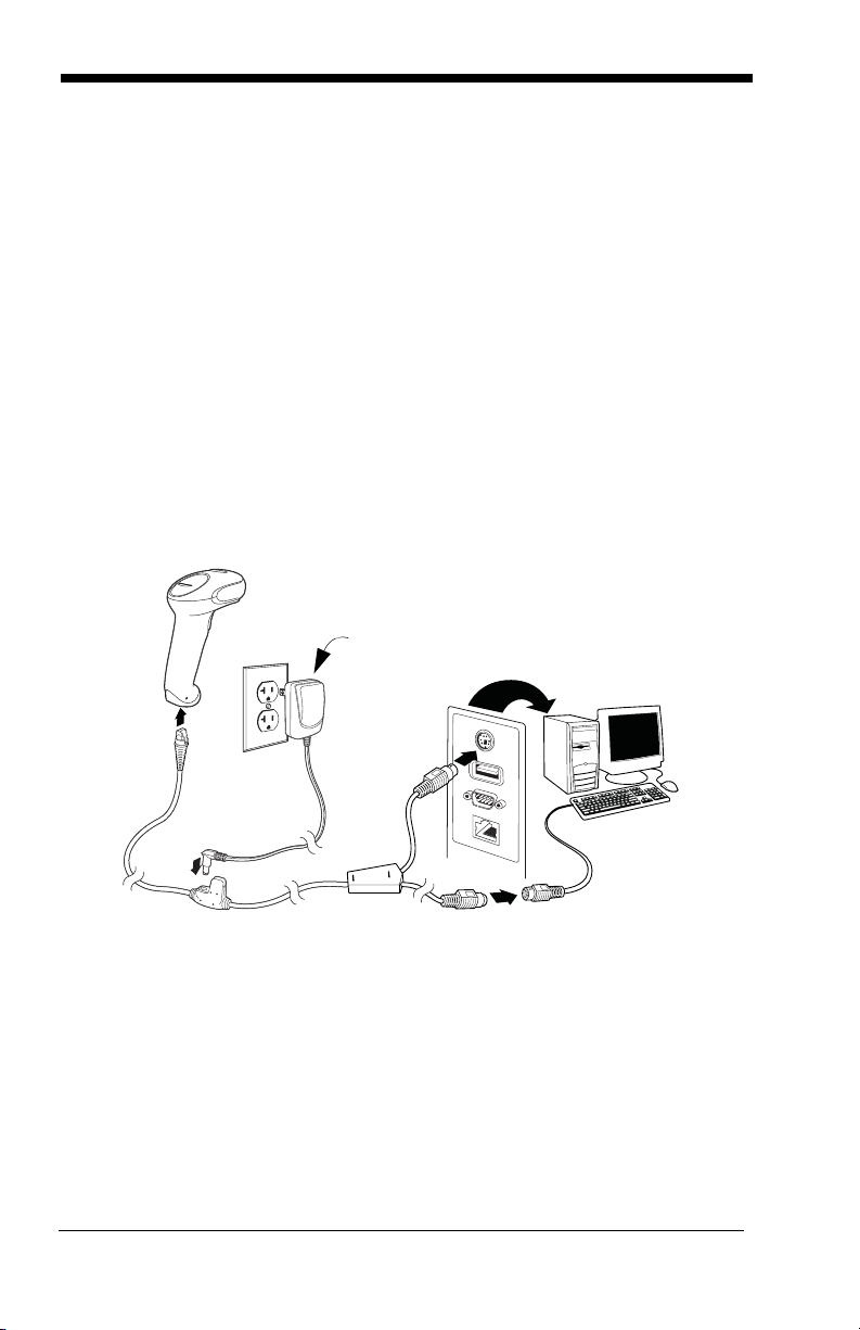
Connecting with Keyboard Wedge
A scanner can be connected between the keyboard and PC as a “keyboard
wedge,” plugged into the serial port, or connected to a portable data termi-
nal in wand emulation or non decoded output mode. The following is an
example of a keyboard wedge connection:
1. Turn off power and disconnect the keyboard cable from the back of the
terminal/computer.
2. Connect the appropriate interface cable to the scanner and to the
terminal/computer.
3. Turn the terminal/computer power back on. The scanner beeps.
4. Verify the scanner operation by scanning a bar code from the Sample
Symbols in the back of this manual. The scanner beeps once.
The unit defaults to an IBM PC AT and compatibles keyboard wedge inter-
face with a USA keyboard. A carriage return (CR) suffix is added to bar
code data.
only if
power
supply is
included
1 - 3
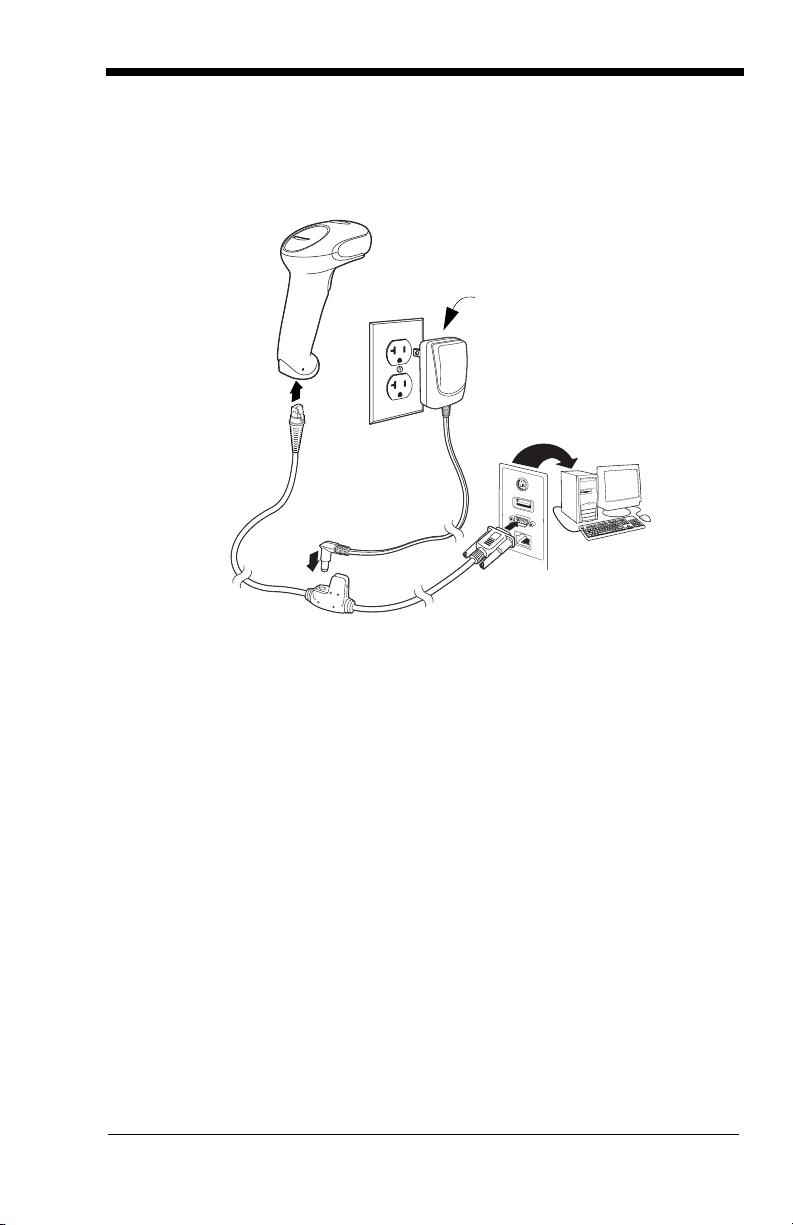
Connecting with RS232 Serial Port
1. Turn off power to the terminal/computer.
2. Connect the appropriate interface cable to the scanner.
3. Plug the serial connector into the serial port on your computer.
Tighten the two screws to secure the connector to the port.
4. Once the scanner has been fully connected, power up the computer.
This interface programs 9600 baud, 8 data bits, no parity, and 1 stop bit.
only if
power
supply is
included
1 - 4
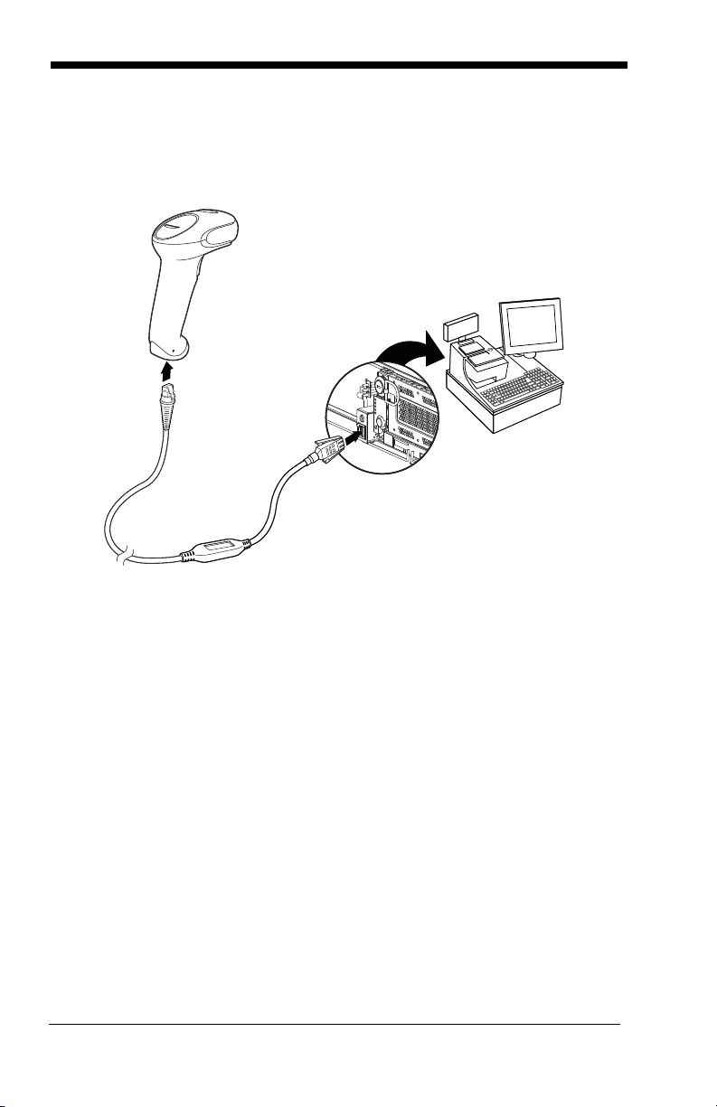
Connecting with RS485
A scanner can be connected for an IBM POS terminal interface.
1. Connect the appropriate interface cable to the device, then to the com-
puter.
2. Turn the terminal/computer power back on. The scanner beeps.
3. Verify the scanner operation by scanning a bar code from the Sample
Symbols in the back of this manual. The scanner beeps once.
For further RS485 settings, refer to RS485, page 2-2.

1 - 5
Reading Techniques
The scanner has a view finder that projects a bright red aiming beam that corre-
sponds to the scanner’s horizontal field of view. The aiming beam should be
centered horizontally over the bar code and must highlight all the vertical bars of
the bar code. It will not read if the aiming beam is in any other direction.
The aiming beam is smaller when the scanner is closer to the code and larger
when it is farther from the code. Symbologies with smaller bars or elements (mil
size) should be read closer to the unit. Symbologies with larger bars or ele-
ments (mil size) should be read farther from the unit. To read single or multiple
symbols (on a page or on an object), hold the scanner at an appropriate dis-
tance from the target, press the button, and center the aiming beam on the sym-
bol. If the code being scanned is highly reflective (e.g., laminated), it may be
necessary to tilt the code up 15° to 18° to prevent unwanted reflection.
Menu Bar Code Security Settings
Honeywell scanners are programmed by scanning menu bar codes or by send-
ing serial commands to the scanner. If you want to restrict the ability to scan
menu codes, you can use the Menu Bar Code Security settings. Please contact
the nearest technical support office (see Technical Assistance on page 12-1) for
further information.
Setting Custom Defaults
You have the ability to create a set of menu commands as your own, custom
defaults. To do so, scan the Set Custom Defaults bar code below before each
menu command or sequence you want saved. If your command requires scan-
ning numeric codes from the back cover, then a Save code, that entire
sequence will be saved to your custom defaults. Scan the Set Custom
Defaults code again before the next command you want saved to your custom
defaults.
Good Read Bad Read

1 - 6
When you have entered all the commands you want to save for your custom
defaults, scan the Save Custom Defaults bar code.
You may have a series of custom settings and want to correct a single setting.
To do so, just scan the new setting to overwrite the old one. For example, if you
had previously saved the setting for Beeper Volume at Low to your custom
defaults, and decide you want the beeper volume set to High, just scan the Set
Custom Defaults bar code, then scan the Beeper Volume High menu code,
and then Save Custom Defaults. The rest of the custom defaults will remain,
but the beeper volume setting will be updated.
Resetting the Custom Defaults
If you want the custom default settings restored to your scanner, scan the Acti-
vate Custom Defaults bar code below. This resets the scanner to the custom
default settings. If there are no custom defaults, it will reset the scanner to the
factory default settings. Any settings that have not been specified through the
custom defaults will be defaulted to the factory default settings.
Save Custom Defaults
Set Custom Defaults
Activate Custom Defaults

1 - 7
Resetting the Factory Defaults
If you aren’t sure what programming options are in your scanner, or you’ve
changed some options and want to restore the scanner to factory default set-
tings, first scan the Remove Custom Defaults bar code, then scan Activate
Defaults. This resets the scanner to the factory default settings.
The Serial Programming Commands, beginning on page 9-1 list the factory
default settings for each of the commands (indicated by an asterisk (*) on the
programming pages).
This selection erases all your settings and resets the scanner to the
original factory defaults.
!
Remove Custom Defaults
Activate Defaults

1 - 8

2 - 1
2
Programming the Interface
Introduction
This chapter describes how to program your system for the desired interface.
Programming the Interface - Plug and Play
Plug and Play bar codes provide instant scanner set up for commonly used
interfaces.
Note: After you scan one of the codes, power cycle the host terminal to have
the interface in effect.
Keyboard Wedge
If you want your system programmed for an IBM PC AT and compatibles
keyboard wedge interface with a USA keyboard, scan the bar code below.
Keyboard wedge is the default interface.
Note: The following bar code also programs a carriage return (CR) suffix.
IBM PS2 Keyboard
The following bar code programs you scanner for an IBM PS2 keyboard
wedge interface with a USA keyboard.
Note: The following bar code also programs a carriage return (CR) suffix.
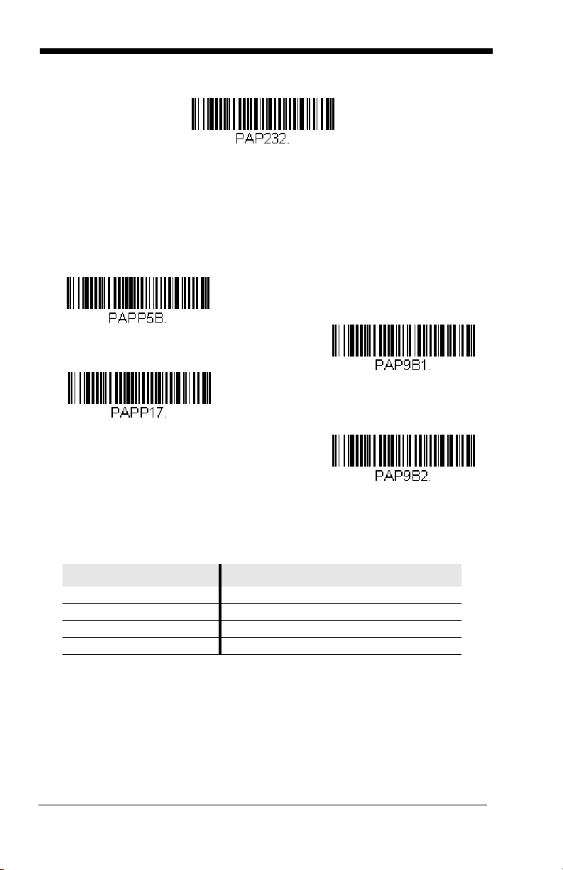
RS232 Serial Port
The RS232 Interface bar code is used when connecting to the serial port
of a PC or terminal. The following RS232 Interface bar code also pro-
grams a carriage return (CR) and a line feed (LF) suffix, baud rate, and
data format as indicated below.
Option Setting
Baud Rate 9600 bps
Data Format 8 data bits, no parity bit, 1 stop bit
IBM PC AT and Compatibles with CR Suffix
IBM PS2 with CR Suffix
2 - 2
RS485
Scan one of the following “Plug and Play” codes to program the scanner for
an IBM POS terminal interface.
Note: After scanning one of these codes, you must power cycle the cash
register.
Each bar code above also programs the following suffixes for each symbol-
ogy:
* Suffixes programmed for Code 128 with IBM 4683 Port 5B, IBM 4683 Port 9B
HHBCR-1, and IBM 4683 Port 17 Interfaces
**Suffixes programmed for Code 128 with IBM 4683 Port 9 HHBCR-2 Interface
Symbology Suffix Symbology Suffix
EAN 8 0C Code 39 00 0A 0B
EAN 13 16 Interleaved 2 of 5 00 0D 0B
UPC A 0D Code 128 * 00 0A 0B
UPC E 0A Code 128 ** 00 18 0B
RS232 Interface
IBM Port 5B Interface
IBM Port 9B
HHBCR-1 Interface
IBM Port 17 Interface
IBM Port 9B
HHBCR-2 Interface

2 - 3
OPOS Mode
The following bar code configures your scanner for OPOS (OLE for Retail
Point of Sale) by modifying the following OPOS-related settings:
Option Setting
Interface RS232
Baud Rate 38400
RS232
Handshaking
Flow Control, No Timeout
XON/XOFF Off
ACK/NAK Off
Data Bits, Stop
Bits, and Parity
8 Data, 1 Stop, Parity None
Prefix/Suffix
Clear All Prefixes and Suffixes
Add Code ID and AIM ID Prefix
Add CR Suffix
Intercharacter
Delay
Off
Symbologies Enable UPC-A with check digit and number system
Enable UPC-E0 with check digit
Enable EAN/JAN-8 with check digit
Enable EAN/JAN-13 with check digit
Enable Code 128
Enable Code 39
Enable OPOS with automatic disable off
OPOS Mode
2 - 4
USB IBM SurePos
Scan one of the following “Plug and Play” codes to program the scanner for
an IBM SurePos (USB handheld scanner) or IBM SurePos (USB tabletop
scanner) interface.
Note: After scanning one of these codes, you must power cycle the cash
register.
Each bar code above also programs the following suffixes for each symbol-
ogy:
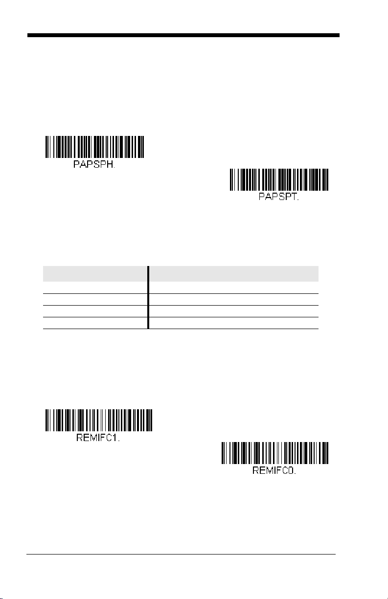
IBM Secondary Interface
On some older IBM cash registers, it may be necessary to disable the sec-
ondary or management interface. In particular, it has been found neces-
sary on IBM registers using the 4690 V2R4 operating system. The
following bar codes are used for this purpose.
Default = Enable Secondary
Interface.
Symbology Suffix Symbology Suffix
EAN 8 0C Code 39 00 0A 0B
EAN 13 16 Interleaved 2 of 5 00 0D 0B
UPC A 0D Code 128 00 18 0B
UPC E 0A Code 39 00 0A 0B
USB IBM SurePos
(USB Handheld Scanner)
Interface
USB IBM SurePos
(USB Tabletop Scanner)
Interface
*Enable Secondary Interface
Disable Secondary Interface

2 - 5
USB PC or Macintosh Keyboard
Scan one of the following codes to program the scanner for USB PC Key-
board or USB Macintosh Keyboard. Scanning these codes also adds a CR
and LF.
USB HID
Scan the following code to program the scanner for USB HID bar code
scanners.
HID Fallback Mode
If you attempt to set a USB interface for your scanner, but the setup fails on
the host system, you can program the scanner to fall back to a HID key-
board interface after a set length of time. For example, if the scanner is
configured for Serial Emulation Mode, but the host system does not have
the correct driver, the scanner would fail. If you set the HID Fallback Mode
for a set length of time, for example, 5 minutes, the scanner would change
to a HID keyboard interface after 5 minutes of trying to configure as serial
emulation.
A unique beep sequence indicates that this mode has been entered. While
in HID Fallback Mode, the scanner will not scan normal bar codes and
sounds a unique beep sequence that indicates the scanner is in Fallback
Mode. Menu codes can still be scanned while in HID Fallback Mode, allow-
ing you to change the scanner’s programming.
U
S
B
K
e
y
b
o
a
r
d
(
P
C
)
USB Keyboard (Mac)
USB Japanese Keyboard (PC)
USB HID Bar Code Scanner

2 - 6
Scan the bar code below, then set the length for the HID Fallback (from 0-
60 minutes) by scanning digits from the Programming Chart, then scanning
Save.
Default = 5 minutes.
USB Serial Commands
USB Serial Emulation
Scan one of the following codes to program the scanner to emulate a regu-
lar RS232-based COM Port. If you are using a Microsoft® Windows® PC,
you will need to download a driver from the Honeywell website
(www.honeywellaidc.com). The driver will use the next available COM Port
number. Apple® Macintosh computers recognize the scanner as a USB
CDC class device and automatically uses a class driver.
Scanning either of these codes also adds a CR and LF.
Note: No extra configuration (e.g., baud rate) is necessary.
CTS/RTS Emulation
HID Fallback Mode
USB Serial Emulation for
Windows XP, Windows Server
2003, and later
USB Serial Emulation for Windows 2000
CTS/RTS Emulation On
* CTS/RTS Emulation Off
 Loading...