


T8611M
(7-Day Programming)
Chronotherm III™
Heat Pump Thermostats
The T8611M Chronotherm III Programmable
Thermostat provides automatic control of multistage heat pump systems and offers users the highest standard of comfort and convenience available with energy savings.
■Full seven-day program capability; different schedules may be selected for every day.
■Can be programmed in hand (with batteries installed) or on the wall to provide up to four temperature periods per day.
■Large digital clock (liquid crystal display) indicates continuous time-of-day, day-of-week, current period and room temperature.
■Adaptive Intelligent Recovery™ brings room temperature to programmed temperature at programmed time, maximizing comfort and energy savings.
■Temperature control program maintains temperature within 1° F of setpoint.
■Temporary program override available by using—
—WARMER and COOLER keys.
—SKIP next period key.
—CHANGE to last period key.
■HOLD TEMP key provided for indefinite program override (vacation/holiday).
■Installer self-test with time delay override saves installation time.
■SYSTEM light-emitting diode (LED) on thermo-
temperature sensing.
stat indicates system is energized.
■AUX. HT., EM. HT., CHECK LEDs available on select models.
■Automatic heat/cool changeover.
■Batteries included provide power to maintain clock and memory during power failures.
■Switching subbase with wiring terminals included.
■Powered directly from control transformer.
■Model available with separate sensor for remote
CONTENTS |
|
Specifications ................................................. |
2 |
Ordering Information ..................................... |
2 |
Selection/Application ..................................... |
5 |
Installation ................................................... |
12 |
Checkout ....................................................... |
18 |
Programming The Thermostat ..................... |
20 |
Operating The Thermostat ........................... |
25 |
Operation ..................................................... |
27 |
Troubleshooting ........................................... |
29 |
Glossary ....................................................... |
30 |
Table of Contents ......................................... |
32 |
1 |
68-0076—1 |
C. H. • Rev. 10-92 • ©Honeywell Inc. 1992 • Form Number 68-0076—1

T8611M
SPECIFICATIONS • ORDERING INFORMATION
Specifications
TRADELINE MODELS
TRADELINE models are selected and packaged to provide ease of stocking and handling and also maximum
replacement value.
TRADELINE models available are listed in Table 1.
TABLE 1—TRADELINE MODELS AVAILABLE.
|
Stages |
Changeover |
Switching |
|
|
|
|
Thermostat |
Heat |
Cool |
Type |
System |
Fan |
Application |
Program |
T8611M* |
3 |
2 |
Automatic |
EM. HT.-HEAT-OFF- |
ON-AUTO |
Heat Pump |
7-Day |
|
|
|
|
AUTO-COOL |
|
|
|
|
|
|
|
|
|
|
|
*Model available with separate sensor for remote temperature sensing.
LIGHT-EMITTING DIODES (LEDs):
SYSTEM LED (yellow) on thermostat lights during thermostat heating and cooling ON cycles.
EM.HT. LED (red) on subbase lights when system switch is in EM.HT. On some systems, light may indicate need to switch to EM.HT. because of heat pump problem.
AUX. HT. LED (green) on subbase lights when thermostat is calling for operation of auxiliary heat.
CHECK LED (yellow) on subbase lights when an equipment or system problem needs to be checked. Consult heat pump literature to determine meaning.
VOLTAGE RATING: 15 to 30 Vac.
CURRENT RATING: 1.6A maximum, total per stage. OPERATING HUMIDITY RANGE: 5 to 90 percent rela-
tive humidity, noncondensing.
OPERATING AMBIENT TEMPERATURE RANGE: 40° F to 110° F [4° C to 43° C].
SET POINT RANGE: 45° F to 88° F [7° C to 31° C].
CALIBRATION: Self-calibrating thermostat and thermometer to ±1° F.
SHIPPING TEMPERATURE: -20° F to +120° F [-29° C to +49° C].
CYCLES PER HOUR ADJUSTMENT:
Auxiliary heating—factory-set at 3 cph (adjustable to
6 cph for special systems); minimum off-time of five minutes.
Nonauxiliary heating and cooling—factory-set (not field adjustable); minimum off-time of five minutes.
FINISH: Beige matte with decorative brushed metal faceplate.
DIMENSIONS: Thermostat (mounted on subbase)—7 in. [178 mm] long, 5-5/16 in. [135 mm] high, 1-3/4 in. [44 mm] deep. See Fig. 1 for subbase dimensions. See Fig. 2 for remote sensor dimensions.
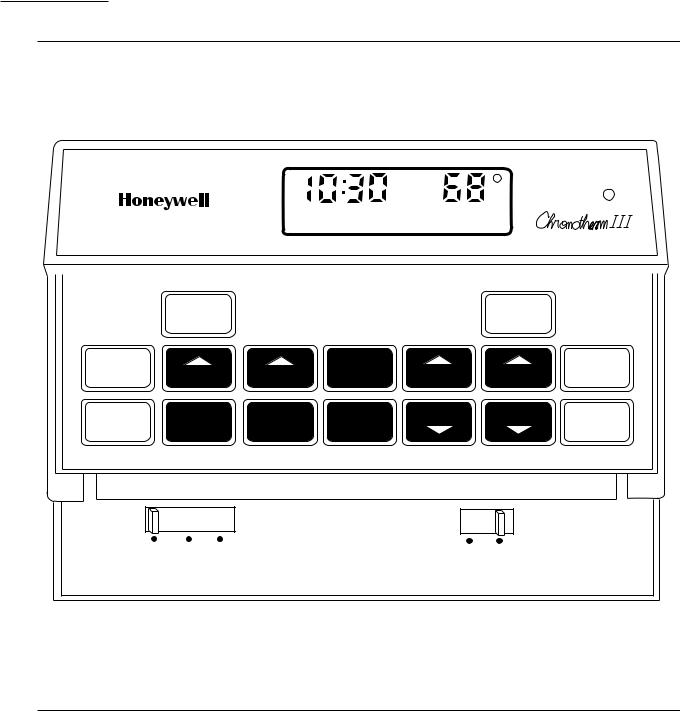
TYPICAL KEYPAD: See Fig. 3. REPLACEMENT PARTS:
202905AA Remote Temperature Sensor. 220529 Replacement Door.
AAA alkaline batteries, available locally. ACCESSORIES:
193121A Cover Plate Assembly. Includes cover plate, adapter ring and screws; 6-9/10 in. x 4-3/4 in. [175 mm x 121 mm]. Covers marks left by old thermostat. Allows mounting on vertical or horizontal outlet box.
TG512 Universal Thermostat Guards. Includes clear or opaque plastic or metal cover, ring base, opaque plastic wallplate, tumbler lock with two keys.
TG586A Locking Cover.
Ordering Information
When purchasing replacement and modernization products from your TRADELINE® wholesaler or distributor, refer to the TRADELINE Catalog or price sheets for complete ordering number, or specify—
1. Model number. 3. Remote temperature sensing, if desired.
2. Number of heat and cool stages desired.
If you have additional questions, need further information or would like to comment on our products or services, please write or phone:
1.Your local Honeywell Home and Building Control Sales Office (check white pages of your phone directory).
2.Home and Building Control Customer Satisfaction Honeywell inc., 1885 Douglas Drive North Minneapolis, Minnesota 55422-4386 (612) 951-1000
In Canada—Honeywell Limited/Honeywell Limitée 740 Ellesmere Road, Scarborough, Ontario M1P 2V9. International sales and service offices in all principal cities of the world. Manufacturing in Australia, Canada, Finland, France, Germany, Japan, Mexico, Netherlands, Spain, Taiwan, United Kingdom, U.S.A.
2

T8611M
SPECIFICATIONS
Fig. 1—T8611 Subbase mounting dimensions in in. [mm].
 1 3132
[50]
13
116 [46]
3
4 32 [104]
5
516 [135]
5
316 [83]
3
4 4 [121]
 7 [179]
M5181A
Fig. 2—202905AA Remote Sensor dimensions in in. [mm].
FRONT |
|
|
|
SIDE |
BACK |
||
|
|
|
|
1 31 |
|
|
2 |
|
|
|
|
|
[51] |
||
|
32 |
|
|
||||
|
|
|
|
||||
|
[50] |
|
|
|
|||
|
|
|
|
|
|
|
|
|
|
|
|
|
|
|
|
|
|
1 |
31 |
[50] |
|
|
|
|
|
|
32 |
|
|
19 |
[8] |
|
|
|
|
|
|
||
|
|
|
|
|
|
64 |
|
3 |
|
|
|
|
|
|
|
4 32 |
|
41 |
[16] |
|
|
|
|
[104] |
|
64 |
9 |
[4] |
|
||
1 3 |
[35] |
|
|
|
64 |
|
|
8 |
|
|
|
|
|
|
|
|
|
|
|
|
|
1 |
DIA. |
|
|
|
|
|
|
2 |
|
|
|
|
|
|
[13] |
|
|
|
|
|
|
|
|
|
1 [25] |
|
M5244 |
|
|
|
|
|
|
|
|
||
|
|
|
|
|
|
|
|
||
|
|
|
|
||||||
|
|
|
|
|
|
|
|||
|
|
|
|
|
|
|
|
|
|
3 |
68-0076—1 |
T8611M
SPECIFICATIONS
Fig. 3—Typical thermostat keypad.
|
|
|
|
AM |
|
SYSTEM |
|
|
|
|
|
|
ROOM |
|
|
|
|
|
WED |
|
|
|
|
|
|
|
MIDDAY |
|
HEAT ON |
|
|
|
|
|
|
|
TEMPERATURE |
|
|
|
RUN |
|
|
|
PRESENT |
|
|
|
|
|
|
SETTING |
|
||
|
PROGRAM |
|
|
|
|
||
|
|
|
|
|
|
||
|
|
|
|
TIME |
|
|
|
SET |
|
|
COPY |
|
|
SKIP |
|
PRESENT |
DAY |
PERIOD |
AHEAD |
WARMER |
NEXT |
||
FROM |
|||||||
DAY/TIME |
PERIOD |
||||||
|
|
|
|
||||
HOLD |
SET |
CANCEL |
COPY |
BACK |
COOLER |
CHANGE |
|
TO LAST |
|||||||
TEMP |
HEAT/COOL |
PERIOD |
TO |
|
|
||
|
|
PERIOD |
|||||
|
|
|
|
|
|
FAN
HEAT OFF COOL |
ON AUTO |
M5360
4

T8611M
SELECTION/APPLICATION
Selection/Application
The T8611 Thermostat uses the latest microelectronic design and control technology to provide home and building owners with the highest level of comfort available and optimal energy savings in a package that is easy to use and easy to live with.
The following section is a guide to selection and application of the best thermostat to meet individual customer needs.
PROGRAMMING
Does the thermostat selected accommodate the customer’s daily schedule, lifestyle or work schedule? Refer to choices below.
TRADELINE |
|
Daily Temperature |
Device |
Programming |
Selection |
T8611G,R* |
Weekday, |
4 heat and |
|
Sat, Sun. |
4 cool |
T8611M |
7-day |
4 heat and |
|
(each day |
4 cool |
|
different) |
|
|
|
|
*Specifications form 68-0057 for information.
IF NEW CONSTRUCTION APPLICATION, CONSIDER
•equipment type (see manufacturer’s specifications)
—system switching required
—status indication provided
•control wiring—number of conductors required to operate equipment and thermostat.
IMPORTANT: The T8611 requires a conductor to transformer common to provide continuous 24V power for thermostat operation. This feature is commonly specified and provided by equipment manufacturer.
IF RETROFIT/REPLACEMENT APPLICATION, CONSIDER
•equipment requirements
—system switching (manual: EM. HT.-HEAT-OFF- COOL, automatic: EM. HT.-HEAT-OFF-AUTO- COOL).
—unique heat pump functions of emergency or supplemental heat, changeover on heat or cool, and status indication.
—Table 3 lists typical applications by manufacturer.
•existing wiring
—Are there enough conductors to operate the equipment and the thermostat? Can a new cable be pulled?
•existing thermostat
—Table 3 is a guide for replacing popular Honeywell standard nonprogrammable thermostats with a T8611.
SECURITY
Does the thermostat selected provide access to programming and the override features that will best suit the application? Refer to choices below.
|
|
|
|
Typical |
|
Access |
Application |
Device |
Free access to |
Home or |
T8611 |
programming |
owner-occupied |
|
and adjustment/ |
commercial |
|
override. |
building. |
|
Restricted |
Public building. |
T8611 with TG512 |
access to |
|
Locking Cover; |
device. |
|
T8611 with remote |
|
|
temperature |
|
|
sensing. |
5 |
68-0076—1 |

T8611M
SELECTION/APPLICATION
Table 2 lists features and wiring terminal functions of the TRADELINE T8611M thermostat.
TABLE 2—T8611M FEATURES AND TERMINALS.
T8611M |
|
|
|
|
FEATURES |
|
|
|
|
|
|
|
|
COMMENTS |
Heating Stages |
|
3 |
|
May be applied to 2-stage heat pump systems; see wiring |
Cooling Stages |
|
2 |
|
diagrams Figs. 6 and 7. |
Changeover |
|
Auto |
|
|
Programming |
|
7-day |
|
|
SYSTEM LED |
|
Yes |
|
Lights on call for heat or cool. |
EM. HEAT LED (red) |
|
Yes |
|
Lights continuously in EM. HEAT mode. |
AUX. HEAT LED (green) |
|
Yes |
|
Lights during call for final auxiliary heat stage. |
CHECK LED (yellow) |
|
Yes |
|
Field wired option; indicates equipment malfunction. |
Remote Temperature |
|
Yes |
|
Available on T8611M7040 only. (202905A Remote Sensor |
Sensing |
|
|
|
included). |
WIRING TERMINAL |
|
|
|
|
FUNCTION |
|
|
|
|
24 Vac Common |
|
C |
|
Must be connected to control transformer to operate |
|
|
|
|
thermostat. |
24 Vac Power |
|
R |
|
|
Compressor, Stage 1 |
|
Y |
|
|
heat and cool. |
|
|
|
|
Compressor, |
|
Y2 |
|
If applying T8611M to 1-stage cooling system, leave Y2 |
Stage 2 cool |
|
|
|
unconnected. |
Second Stage Heat |
|
W2 |
|
If applying T8611M to 2-stage heat systems in which the |
Auxiliary (Resistive) |
|
|
|
second stage is compressorized, connect stage 2 to W2; |
Third Stage Heat |
|
W3 |
|
leave W3 unconnected. |
|
|
|
|
If 2-stage heat system in which the second stage is auxillary |
|
|
|
|
(electric resistive), connect auxiliary stage to W3; leave |
|
|
|
|
W2 unconnected. |
Fan |
|
G |
|
|
Changeover Heat Mode |
|
B |
|
O/B changeover terminals are energized continuously |
|
|
|
|
following first call for cool or heat, respectively. |
|
|
|
|
|
Changeover Cool Mode |
|
O |
|
|
|
|
|
|
|
System Monitor, |
|
L |
|
Energizes EM. HEAT LED when externally powered. |
continuously energized |
|
|
|
|
in EM. HEAT mode. |
|
|
|
|
Emergency Heat |
|
E |
|
|
energized on call for |
|
|
|
|
stage 1 heat in |
|
|
|
|
EM. HEAT mode |
|
|
|
|
Check LED terminals |
X1 |
|
X2 |
See wiring diagrams for hookup alternatives. |
to indicate equipment |
|
|
|
|
malfunction |
|
|
|
|
Remote Temperature |
S1 |
S2 |
S3 |
Available on T8611M7040 only. Must be connected to |
Sensing |
|
|
|
202905A Remote Sensor for proper thermostat operation. |
|
|
|
|
|
6

T8611M
SELECTION/APPLICATION
TABLE 3—T8611 GUIDE FOR REPLACING POPULAR T874 AND T872 THERMOSTATS,
BY EQUIPMENT MANUFACTURER.
(NOTE: Also see form 70-6627, Heat Pump Thermostat Cross Reference Guide, for wiring hookup illustrations.)
Thermostat (Subbase Included) |
|
|
|
|
|
|
|
|
|
|||
Auto |
Manual |
|
|
|
|
|
|
|
|
|
|
|
Changeover |
Changeover |
|
|
|
|
|
|
|
|
|
|
|
Weekday, |
Weekday, |
|
|
|
|
|
|
|
|
|
|
|
Sat, Sun |
Sat, Sun |
|
Auto |
|
|
|
|
|
|
|
|
|
T8611G1004 |
T8611R1000 |
Changeover |
|
|
|
|
|
|
|
|
|
|
T8611G1012 (° C) |
T8611R1042 (° C) |
|
7-day |
|
|
|
|
|
|
|
|
|
T8611G1103 |
T8611R1141 |
T8611M7008 |
|
|
|
|
|
|
|
|
|
|
(Premier White) |
(Premier White) |
T8611M7040c |
Thermostat |
|
Subbase |
Thermostat |
Subbase |
|
|
|
|
|
(also see form 68-0057, Specifications) |
T874 |
|
Q674 |
T872 |
Q672 |
Comments |
|
|
|
|||
|
|
|
|
Amana |
|
|
|
|
|
|
|
|
|
• |
|
|
D1009 |
|
F1022 |
D1003 |
F1026 |
Separate first stage |
|
|
|
|
• |
|
|
D1017 |
|
|
D1011 |
|
heat/cool terminals W1, Y1. |
|||
|
• |
|
|
D1165 |
|
|
D1300 |
|
|
|
|
|
|
|
|
|
Arco/Comfort Maker |
|
|
|
|
|
|||
• |
a |
|
• |
na |
|
na |
na |
na |
Check LED optional; |
|
|
|
• |
|
|
|
|
||||||||
|
|
|
|
|
|
|
|
|
X = X1, jump X2 to C. |
|||
|
|
|
|
Arco/Friedrich |
|
|
|
|
|
|
||
• |
a |
|
• |
na |
|
na |
na |
na |
Changeover on heat, |
|
|
|
• |
|
|
|
|
||||||||
|
|
|
|
|
|
|
|
|
check LED optional. |
|
|
|
|
|
|
|
Bard |
|
|
|
|
|
|
|
|
• |
a |
|
• |
N1024 |
|
F1261 |
N1036 |
F1299 |
Changeover on heat (typical), |
|||
• |
|
|
||||||||||
• |
• |
|
• |
R1129 |
|
L1181 |
R1146 |
L1185 |
check LED optional, equipment |
|||
|
|
|
|
|
|
|
|
|
terminal W1 to thermostat B. |
|||
|
|
|
|
Bryant, Day-Night, Payne |
|
|
|
|
|
|||
•b |
•a,b |
|
•b |
G1451 |
|
F1113b |
G1166 |
F1125 |
Check LED optional; F = X1, |
|||
• |
a |
|
• |
G1261 |
|
F1253 |
|
|
jump X2 to C. Note: P terminal |
|||
• |
|
|
|
|
||||||||
• |
a |
|
• |
J1010 |
|
L1371 |
G1174 |
|
available |
on |
manual |
|
• |
|
|
|
|||||||||
changeover |
a |
|
|
|
|
|
|
|
|
|
|
|
• |
|
• |
R1335 |
|
L1405 |
|
|
(T8611R) models only. |
||||
• |
|
|
|
|
||||||||
|
a |
|
|
Carrier |
|
|
|
|
|
|
|
|
• |
|
• |
G1055 |
|
J1035 |
G1075 |
J1054 |
Check LED optional (typical) |
||||
• |
|
|
||||||||||
• |
• |
|
• |
G1071 |
|
L1041 |
G1158 |
L1052 |
|
|
|
|
• |
• |
|
• |
G1121 |
|
L1397 |
G1182 |
|
|
|
|
|
• |
• |
|
• |
|
|
P1005 |
G1273 |
|
|
|
|
|
• |
• |
|
• |
|
|
|
G1307 |
|
|
|
|
|
• |
• |
|
• |
|
|
|
G1257 |
L1169 |
|
|
|
|
• |
• |
|
• |
J1002 |
|
L1371 |
|
|
|
|
|
|
• |
• |
|
• |
J1028 |
|
L1074 |
|
|
|
|
|
|
|
|
|
• |
D1074 |
|
F1059 |
|
|
Multistage heat pump |
|||
|
|
|
• |
|
|
F1030 |
|
|
|
|
|
|
|
|
|
• |
|
|
F1063 |
|
|
|
|
|
|
|
|
|
• |
|
|
E1114 |
|
|
No Supl. Ht. function |
|
|
|
|
|
|
• |
|
|
E1042 |
|
|
No Supl. Ht. function |
|
|
|
|
|
|
• |
D1264 |
|
L1116 |
|
|
Multistage heat pump |
|||
|
|
|
|
Command |
|
Aire |
|
|
|
|
|
|
|
|
|
|
|
|
|
|
|
|
|
||
• |
• |
|
• |
H1005 |
|
C1041 |
H1009 |
C1086 |
No AUX. HEAT or EM. |
|||
• |
• |
|
• |
G1352 |
|
C1066 |
|
|
HEAT required; Y1 = 0 |
|||
a No CHECK LED. |
|
|
|
|
|
|
|
|
|
|
|
|
b Dual transformer requires conversion to single transformer. |
|
|
|
|
|
|
||||||
c Model includes separate sensor for remote temperature sensing. |
|
|
|
(continued) |
||||||||
7 |
68-0076—1 |

T8611M
SELECTION/APPLICATION
TABLE 3—T8611 GUIDE FOR REPLACING POPULAR T874 AND T872 THERMOSTATS,
BY EQUIPMENT MANUFACTURER (Continued).
(NOTE: Also see form 70-6627, Heat Pump Thermostat Cross Reference Guide, for wiring hookup illustrations.)
Thermostat |
(Subbase |
Included) |
|
|
|
|
|
|
|
|
|
|
|
|||
Auto |
Manual |
|
|
|
|
|
|
|
|
|
|
|
|
|
||
Changeover |
Changeover |
|
|
|
|
|
|
|
|
|
|
|
|
|
||
Weekday, |
Weekday, |
|
|
|
|
|
|
|
|
|
|
|
|
|
||
Sat, Sun |
Sat, Sun |
|
Auto |
|
|
|
|
|
|
|
|
|
|
|
||
T8611G1004 |
T8611R1000 |
Changeover |
|
|
|
|
|
|
|
|
|
|
|
|||
T8611G1012 (° C) |
T8611R1042 (° C) |
|
7-day |
|
|
|
|
|
|
|
|
|
|
|
||
T8611G1103 |
T8611R1141 |
T8611M7008 |
|
|
|
|
|
|
|
|
|
|
|
|||
(Premier White) |
|
|
(Premier White) |
|
T8611M7040c Thermostat |
Subbase Thermostat |
Subbase |
|
||||||||
|
|
|
|
|||||||||||||
|
|
|
|
|
|
T874 |
Q674 |
T872 |
Q672 |
Comments |
||||||
(also see |
form 68-0057, Specifications) |
|
||||||||||||||
|
|
|
a |
|
|
|
Coleman |
|
|
|
|
|
|
|
|
|
|
|
|
|
|
|
|
|
|
|
|
|
|||||
• |
|
• |
|
R1368 |
|
|
L1421 |
na |
|
na |
Late models optional check |
|||||
• |
|
|
|
|
|
|||||||||||
|
|
|
|
|
|
|
|
|
|
|
|
|
|
|
|
LED. Z = X2, jump X1 and C, |
|
|
|
|
|
|
|
|
|
|
|
|
|
|
|
|
K = L. |
• |
• |
|
• |
|
na |
|
|
na |
na |
|
na |
Earlier T.H.E. models with |
||||
|
|
|
|
|
|
|
|
|
|
|
|
|
|
|
|
reverse-acting EM. HT. |
|
|
|
|
|
|
|
|
|
|
|
|
|
|
|
|
require relay isolation. |
|
|
|
|
|
|
|
Crispaire/Marvair |
|
|
|
|
|
||||
|
|
|
|
|
|
|
|
|
|
|
|
|||||
• |
• |
|
• |
|
G1089 |
F1162 |
|
G1208 |
|
F1166 |
|
|||||
|
|
|
|
|
|
|
|
|
|
|
F1204 |
|
|
|
F1323 |
|
• |
• |
|
• |
|
R1111 |
L1215 |
R1156 |
L1094 |
|
|||||||
|
|
|
|
|
|
|
Fedders/Airtemp/Climatrol |
|
|
|
||||||
|
|
|
•a |
|
|
|
C1398 |
L1090 |
C1509 |
|
L1102 Separate first stage heat/cool |
|||||
|
|
|
•a |
|
|
|
C1406 |
|
|
C1517 |
|
|
terminals required; check LED |
|||
|
|
|
•a |
|
|
|
C1414 |
|
|
C1541 |
|
|
optional; equipment terminal |
|||
|
|
|
|
|
|
|
|
|
|
|
|
|
|
|
|
K to thermostat E. |
|
|
|
a |
|
|
|
Florida Heat Pump |
|
|
|
|
|
||||
|
|
|
|
|
|
|
|
|
|
|
||||||
• |
|
• |
|
na |
na |
|
na |
|
na |
Optional check LED; |
||||||
• |
|
|
|
|
||||||||||||
|
|
|
|
|
|
|
|
|
|
|
|
|
|
|
|
X = X1, jump X2 to C. |
|
|
|
|
|
|
|
Heatwave/Southwest |
|
Mfg. |
|
|
|
||||
|
|
|
|
|
|
|
|
|
|
|
||||||
• |
• |
|
• |
|
G1105 |
F1170 |
G1232 |
F1224 |
|
|||||||
|
|
|
|
|
|
|
Heil |
|
Quaker/Whirlpool/Tempstar |
|
|
|||||
|
|
|
|
|
|
|
|
|
||||||||
• |
• |
|
• |
|
R1137 |
|
|
|
L1132 |
R1172 |
|
L1193 |
Equipment terminal B |
|||
|
|
|
|
|
|
|
|
|
|
|
|
|
|
|
|
to thermostat C. |
|
|
|
|
|
|
|
Honeywell |
|
|
|
|
|
|
|
|
|
|
|
|
|
|
|
|
|
|
|
|
|
|
|
|
||
|
|
|
• |
|
|
|
A-D (typ.) |
|
|
|
F1006 |
|
A-D (typ.) |
|
F1000 |
Separate first stage |
|
|
|
• |
|
|
|
|
|
|
|
F1022 |
|
|
|
F1026 |
heat/cool terminals. |
|
|
|
• |
|
|
|
|
|
|
|
F1048 |
|
|
|
F1042 |
|
|
|
|
• |
|
|
|
C1000 |
|
|
F1089 |
|
C1004 |
|
F1075 |
|
|
• |
• |
|
|
|
C1018 |
|
|
|
|
C1038 |
|
|
°C |
|||
• |
• |
|
|
|
C1117 |
|
|
|
|
C1350 |
|
|
||||
• |
• |
|
|
|
C1240 |
|
|
|
|
C1566 |
|
|
°C |
|||
• |
• |
|
• |
|
G1246 |
|
|
F1212 |
|
G1224 |
|
F1208 |
TRADELINE |
|||
• |
• |
|
• |
|
G1444 |
|
|
|
|
G1000 |
|
F1018 |
°C |
|||
• |
• |
|
• |
|
|
|
|
|
|
|
G1018 |
|
|
|||
• |
• |
|
• |
|
G1212 |
|
|
F1238 |
|
G1083 |
|
F1158 |
|
|||
• |
• |
|
• |
|
G1139 |
|
|
|
|
|
|
|||||
a No CHECK LED. |
|
|
|
|
|
|
|
|
|
|
|
|
|
|||
b Dual transformer requires conversion to single transformer. |
|
|
|
|
||||||||||||
c Model includes separate sensor for remote temperature sensing. |
|
|
|
(continued) |
||||||||||||
8

T8611M
SELECTION/APPLICATION
TABLE 3—T8611 GUIDE FOR REPLACING POPULAR T874 AND T872 THERMOSTATS, BY EQUIPMENT MANUFACTURER (Continued).
(NOTE: Also see form 70-6627, Heat Pump Thermostat Cross Reference Guide, for wiring hookup illustrations.)
Thermostat |
(Subbase |
Included) |
|
|
|
|
|
|
|
|
|
|
|
|
||
Auto |
Manual |
|
|
|
|
|
|
|
|
|
|
|
|
|
|
|
Changeover |
Changeover |
|
|
|
|
|
|
|
|
|
|
|
|
|
|
|
Weekday, |
Weekday, |
|
|
|
|
|
|
|
|
|
|
|
|
|
|
|
Sat, Sun |
Sat, Sun |
|
Auto |
|
|
|
|
|
|
|
|
|
|
|
|
|
T8611G1004 |
T8611R1000 |
Changeover |
|
|
|
|
|
|
|
|
|
|
|
|
||
T8611G1012 (° C) |
T8611R1042 (° C) |
|
7-day |
|
|
|
|
|
|
|
|
|
|
|
|
|
T8611G1103 |
T8611R1141 |
T8611M7008 |
|
|
|
|
|
|
|
|
|
|
|
|
||
(Premier White) |
|
(Premier White) |
|
T8611M7040c Thermostat |
|
Subbase Thermostat |
Subbase |
|
|
|
|
|
|
|||
(also see |
form 68-0057, Specifications) |
|
T874 |
|
Q674 |
T872 |
Q672 |
|
Comments |
|
|
|
|
|||
|
|
|
|
|
|
Honeywell |
|
(continued) |
|
|
|
|
|
|
|
|
|
|
|
|
|
|
|
|
|
|
|
|
|
|
|||
• |
• |
|
• |
|
N1016 |
|
F1220 |
N1002 |
F1133 Changeover on heat; equip- |
|||||||
• |
• |
|
• |
|
N1040 |
|
F1261 |
N1028 |
F1216 ment terminal C to thermostat |
|||||||
• |
• |
|
• |
|
R1004 |
|
B1042 |
R1008 |
B1046 Y, W1 to B, K to E. |
|
|
|||||
• |
• |
|
• |
|
|
|
B1109 |
R1057 |
L1037 |
|
|
|
|
|
|
|
• |
• |
|
• |
|
R1152 |
|
L1207 |
R1198 |
L1227 |
|
|
|
|
|
|
|
• |
• |
|
• |
|
R1285 |
|
L1157 |
|
|
|
|
|
|
|
|
|
• |
• |
|
• |
|
R1350 |
|
L1181 |
|
|
|
|
|
|
|
|
|
|
|
|
|
|
|
Janitrol/Tappan |
|
|
|
|
|
|
|
|
||
|
|
|
|
|
|
|
|
|
|
|
|
|
|
|||
• |
• |
|
• |
|
G1147 |
|
F1139 |
G1109 |
F1117 Equipment terminal C to |
|||||||
|
|
|
|
|
|
|
|
|
|
|
|
thermostat C. |
|
|
|
|
VA |
|
|
|
|
Lennox |
|
|
|
|
|
NOTE: Rewire for single 75 |
|||||
|
|
|
|
|
|
|
|
|
||||||||
|
|
|
|
|
|
|
|
|
|
transformer if two-transformer |
||||||
|
|
|
|
|
|
|
|
|
|
|
|
|||||
• |
• |
|
• |
|
G1014 |
|
F1113 |
G1026 |
F1067 |
|
system. |
|
|
|
|
|
|
|
|
|
°C |
|
|
|
|
||||||||
• |
• |
|
• |
|
G1022 |
|
E1148 |
G1125 |
E1019 |
|
|
|
|
|
||
• |
• |
|
• |
|
G1162 |
|
|
G1091 |
|
|
DoD specs—use guard. |
|||||
• |
• |
|
• |
|
G1154 |
|
F1105 |
G1323 |
L1201 |
|
|
|
|
|
|
|
• |
• |
|
• |
|
R1024 |
|
B1160 |
|
|
|
|
|
|
|
|
|
• |
• |
|
• |
|
R1040 |
|
B1202 |
|
|
|
|
|
|
|
|
|
• |
• |
|
• |
|
R1178 |
|
L1355 |
|
|
|
|
|
|
|
|
|
• |
• |
|
• |
|
|
|
L1165 |
|
|
|
|
|
|
|
|
|
• |
• |
|
• |
|
C1148 |
|
L1165 |
|
|
|
|
|
|
|
|
|
|
|
|
|
• |
|
D1207 |
|
L1199 |
|
|
|
Two-speed unit; optional check |
||||
|
|
|
|
• |
|
|
|
L1389 |
|
|
|
LED; thermistor A not used. |
||||
Ter- |
|
|
|
|
|
|
|
|
|
|
minal |
Conversion |
||||
Guide: |
|
|
|
|
|
|
|
|
|
|
|
Lennox Standard |
||||
|
|
|
|
|
|
|
|
|
|
|
|
Transformer |
||||
|
|
|
|
|
|
|
|
|
|
|
|
|
|
|
|
|
|
|
|
|
|
|
|
|
|
|
|
|
Common |
|
X |
C |
|
|
|
|
|
|
|
|
|
|
|
|
|
Transformer |
|
|
|
|
|
|
|
|
|
|
|
|
|
|
|
|
Power |
VR (in) |
R |
||
|
|
|
|
|
|
|
|
|
|
|
|
|
V (out) |
|
|
|
|
|
|
|
|
|
|
|
|
|
|
|
Compressor |
|
M |
Y |
|
|
|
|
|
|
|
|
|
|
|
|
|
|
|
M2 |
Y2 |
|
|
|
|
|
|
|
|
|
|
|
|
|
Aux. Heating |
|
Y |
W2 |
|
|
|
|
|
|
|
|
|
|
|
|
|
Fan |
|
F |
G |
|
|
|
|
|
|
|
|
|
|
|
|
|
Changeover |
|
R |
O |
|
|
|
|
|
|
|
|
|
|
|
|
|
System Monitor |
|
L |
L,X1,X2 |
|
|
|
|
|
|
|
|
|
|
|
|
Em.Heat (cycling) |
E |
E |
|||
|
|
|
|
|
|
|
|
|
|
|
|
Thermistor |
|
A |
T (not |
|
|
|
|
|
|
|
|
|
|
|
|
|
|
|
|
required) |
|
a No CHECK LED. |
|
|
|
|
|
|
|
|
|
|
|
(continued) |
|
|||
|
|
|
|
|
|
|
|
|
|
|
|
|
|
|||
b Dual transformer requires conversion to single transformer. |
|
|
|
|
|
68-0076—1 |
||||||||||
|
|
|
|
|
|
|
9 |
|
|
|
|
|
||||
c Model includes separate sensor for remote temperature sensing. |
|
|
|
|
|
|
|
|
||||||||

T8611M
SELECTION/APPLICATION
TABLE 3—T8611 GUIDE FOR REPLACING POPULAR T874 AND T872 THERMOSTATS,
BY EQUIPMENT MANUFACTURER (Continued).
(NOTE: Also see form 70-6627, Heat Pump Thermostat Cross Reference Guide, for wiring hookup illustrations.)
Thermostat (Subbase Included) |
|
|
|
|
|
|
|||
Auto |
Manual |
|
|
|
|
|
|
|
|
Changeover |
Changeover |
|
|
|
|
|
|
|
|
Weekday, |
Weekday, |
|
|
|
|
|
|
|
|
Sat, Sun |
Sat, Sun |
|
Auto |
|
|
|
|
|
|
T8611G1004 |
T8611R1000 |
Changeover |
|
|
|
|
|
|
|
T8611G1012 (° C) |
T8611R1042 (° C) |
|
7-day |
|
|
|
|
|
|
T8611G1103 |
T8611R1141 |
T8611M7008 |
|
|
|
|
|
|
|
(Premier White) |
(Premier White) |
T8611M7040c |
Thermostat |
Subbase |
Thermostat |
Subbase |
|
|
|
(also see |
form 68-0057, Specifications) |
T874 |
Q674 |
T872 |
Q672 |
Comments |
|||
|
|
|
|
Luxaire |
|
|
|
|
|
• |
• |
|
• |
G (Borg |
F1188 |
G1315 |
F1281 |
|
|
|
|
|
|
Warner) |
|
|
|
|
|
|
|
|
|
Magic Chef |
|
|
|
|
|
|
• |
|
|
na |
na |
na |
na |
Earlier PB series, separate first |
|
|
a |
|
|
|
|
|
|
stage heat/cool. |
|
• |
|
• |
na |
na |
na |
na |
Late PE series, optional check |
||
• |
|
||||||||
|
|
|
|
|
|
|
|
LED; X1 = X1, jump X2 to R. |
|
|
|
|
|
Rheem/Ruud |
|
|
|
|
|
• |
• |
|
• |
G1097 |
F1238 |
G1133 |
F1158 |
|
|
• |
• |
|
• |
G1238 |
|
G1141 |
L1157 |
|
|
• |
• |
|
• |
|
|
R1081 |
L1045 |
|
|
• |
• |
|
• |
G1220 |
|
R1107 |
L1136 |
|
|
• |
• |
|
• |
R1079 |
|
|
|
|
|
• |
• |
|
• |
R1095 |
|
|
|
|
|
|
|
|
|
Square D/Sun Dial |
|
|
|
|
|
|
•a |
|
|
C1224 |
F1071 |
C1525 |
F1182 |
Separate first stage heat/cool |
|
|
|
|
|
|
|
|
|
required; optional check LED; |
|
|
|
|
|
|
|
|
|
X = X1, jump X2 to R. |
|
|
|
|
|
Trane/General Electric |
|
|
|
||
• |
a |
|
• |
G1204 |
J1043 |
G1059 |
J1039 |
Optional check LED; F = X1, |
|
• |
|
||||||||
|
|
|
|
|
|
|
|
jump X2 to C; T not used; |
|
|
|
|
|
|
|
|
|
equipment terminal B to ther- |
|
|
|
|
|
|
|
|
|
mostat C, R to R, Y to Y (Y1 + |
|
|
|
|
|
|
|
|
|
W1), W to W2, G to G, 0 to 0, |
|
|
|
|
|
|
|
|
|
X2 to E. |
|
|
|
|
|
Weather King |
|
|
|
|
|
• |
• |
|
• |
na |
na |
G1265 |
F1265 |
Optional check LED; X = X1, |
|
|
|
|
|
|
|
|
|
jump X2 to R; equipment ter- |
|
|
|
|
|
|
|
|
|
minal C to thermostat C, W1 |
|
|
|
|
|
|
|
|
|
to Y (W1 + Y1), E to W2, |
|
|
|
|
|
|
|
|
|
Y1 to 0. |
|
aNo CHECK LED.
bDual transformer requires conversion to single transformer.
cModel includes separate sensor for remote temperature sensing.
(continued)
10
 Loading...